

Page 1
FCC Numbers: ROG466837HO553R24
ROG466837HO553R58
28 Clover Lane Barrington, IL 60010
Voice: 847-686-0800
Page 2

Radio / Antenna Connection Instructions
NOTICES
Important Note on Modifications
Intentional or unintentional changes or modifications to the equipment must not be made unless under the express
consent of the party responsible for compliance. Any such modifications could void the user’s authority to
operate the equipment and will void the manufacturer’s warranty.
U.S. Federal Communication Commission (FCC) Notifications
This device complies with part 15 of the U.S. FCC Rules and Regulations. Operation is subject to the following
two conditions: (1) This device may not cause harmful interference, and (2) This device must accept any
interference received, including interference that may cause undesired operation.
This equipment has been tested and found to comply with the limits for a Class B digital device, pursuant to Part
15 of the U.S. FCC Rules and Regulations. These limits are designed to provide reasonable protection against
harmful interference in a residential installation. This equipment generates, uses, and can radiate radio-frequency
energy and, if not installed and used in accordance with these instructions, may cause harmful interference to
radio communications. If this equipment does cause harmful interference to radio or television reception, which
can be determined by turning the equipment on and off, the user is encouraged to correct the interference by one
or more of the following measures:
• Increase the separation between the affected equipment and the unit;
• Connect the affected equipment to a power outlet on different circuit from that which the receiver is
connected to;
• Consult the dealer and/or experienced radio/TV technician for help
Product Description
The products listed in this manual operate in the ISM 2400-2483.5 MHz and the U-NII 5725-5850 MHz
frequency band range. Those products that operate in the 2.4GHz range have a minimum frequency of 2415 MHz
and a maximum frequency of 2457.5 MHz. Despite the usage in the same frequency range, the products listed in
this manual are not 802.11 devices as they use an access method of TDD/TDMA with a modulation of BFSK.
All of the possible frequency options for the 2.4 GHz products are shown in the configuration snapshot in the
Radio Configuration section of this manual.
RF Exposure Analysis
The following relates to the guidelines set forth by FCC OET Bulletin 65; which states that the maximum radio
frequency power density exposure limit is 10 Watt/m
distances have been calculated for each frequency range. As a result of the change of gain in each antenna, a table
has been complied to show the safe distances for each radio and antenna combination. This table is shown below.
The formula used to compute the peak power density (S) in the far-field of a radio frequency source that transmits
power P and linear antenna gain G at a distance d is:
2
(1 mWatt/cm2). The corresponding compliance safe
GP
S
=
4*d
π
2
ii
Page 3
Radio / Antenna Connection Instructions
The table below is the result of the equation above with P = 168mW for 2.4GHz combinations and P = 340mW
for 5.7GHz combinations. With this information the safe distance for each radio and antenna combination can be
calculated. All the values were calculated using S = 10 W/m2 (1 mWatt/cm2).
Antenna dBi
2.4 GHz Safe
Distance d (m)
2.4 GHz Safe
Distance d (cm)
5.7GHz Safe
Distance d (m)
5.7GHz Safe
Distance d (cm)
3 0.0516 5.1648 0.0735 7.3474
5 0.0650 6.5020 0.0925 9.2498
12 0.1456 14.5563 0.2071 20.7078
13 0.1633 16.3324 0.2323 23.2346
14 0.1833 18.3252 0.2607 26.0696
17 0.2589 25.8851 0.3682 36.8243
22 0.4603 46.0309 0.6548 65.4839
26 0.7295 72.9541 1.0378 103.7850
29 n/a n/a 1.4660 146.002
According to FCC 1.1310: The criteria listed in the following table shall be used to evaluate the environmental
impact of human exposure to radio-frequency (RF) radiation as specified in 1.1307(b):
LIMITS FOR MAXIMUM PERMISSIBLE EXPOSURE (MPE)
Frequency Range
(MHz)
Electric Field
Strength (V/m)
Magnetic Field
Strength (A/m)
Power Density
(mW/cm
2
)
Average Time (in
minutes)
Limits for Occupational / Control Exposure
300 – 1,500 … … F/300 6
1,500 – 100,000 … … 5 6
Limits For General Population / Uncontrolled Exposure
300 – 1,500 … … F/1500 6
1,500 – 100,000 … … 1.0 30
F = Frequency in Megahertz
iii
Page 4

Radio / Antenna Connection Instructions
Table of Contents
Cautions and Warnings................................................................................................................. 2
WARNINGS............................................................................................................................................2
2.4 GHz Radios and Antennas....................................................................................................... 3
ATE24-1026 and ATE24-2026...............................................................................................................3
ATE24-10140 and ATE24-20140...........................................................................................................3
ATE24-101690 and ATE24-201690.......................................................................................................3
ATE24-103MPOB...................................................................................................................................4
ATE24-105MPO .....................................................................................................................................4
ATE24-1012MPO ...................................................................................................................................4
ATE24-1012MPBM................................................................................................................................5
ATE24-1017MPBM and ATE24-2017MPBM .....................................................................................5
ATE24-1022MPT and ATE24-2022MPT.............................................................................................5
ATE24-1014WSPR120...........................................................................................................................6
5.7 GHz Radios and Antennas....................................................................................................... 7
ATE57-1014OMP and ATE57-2014OPP .............................................................................................7
ATE57-101690 and ATE57-201690.......................................................................................................7
ATE57-103MPOB...................................................................................................................................7
ATE57-105MPO .....................................................................................................................................8
ATE57-1012MPO ...................................................................................................................................8
ATE57-1014WSPR120...........................................................................................................................8
ATE57-1012MPBM and ATE57-2012MPBM .....................................................................................9
ATE57-1029PAC and ATE57-2029PAC ..............................................................................................9
Radio Installation......................................................................................................................... 10
Securing Radio/Antenna Connection ......................................................................................... 11
Radio Configuration.................................................................................................................... 12
Special Radio Configuration Required For All ATE24-1026, ATE24-2026, ATE24-1022MPT,
and ATE24-2022MPT Products..........................................................................................................12
1
Page 5
Radio / Antenna Connection Instructions
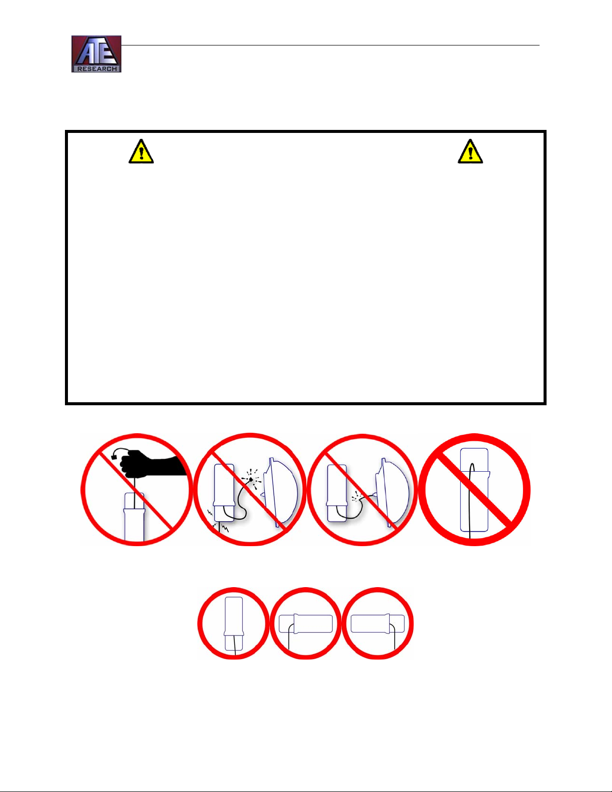
Cautions and Warnings
WARNINGS
1. Do not pull on, or hold the radio by, the N-connector cable.
2. Do not connect, or disconnect, the radio to the antenna feed
while the radio is turned on.
3. Do not power on the radio without the antenna connected.
4. Do not crimp the N-connector cable. The cable should be
straight or have a large bending radius at all times.
5. Be cautious when installing the bottom radio cover, as the Nconnector cable may be caught.
6. Fasten the N-connector with self-adhesive vulcanizing tape as
described in the Securing Radio/Antenna Connection section.
7. This radio and antenna must be professionally installed as
provided.
2
Page 6

Radio / Antenna Connection Instructions
2.4 GHz Radios and Antennas
View the Radio Installation, Securing Radio/Antenna Connection, and Radio Configuration
sections, starting on Page 10, for more information on radio operation and connection
procedures for each of the radio and antenna combinations below.
ATE24-1026 and ATE24-2026
Radio Type: 10mbit and 20mbit Point-to-point respectively
Antenna Model: MaxRad Model MPR24026PTNF
Antenna Rating: 26 dbi
Antenna Type: 3 ft Directional Parabolic Dish
Note: Please see the Radio Configuration section on Page 12 for special
instructions on the configuring the radio for antennas over 20dB.
ATE24-10140 and ATE24-20140
Radio Type: 10mbit Multi-point and 20mbit Point-to-point respectively
Antenna Model: Comtelco Model BS2400XL12-0
Antenna Rating: 14 dbi
Antenna Type: 60 inch Omni-directional Antenna
ATE24-101690 and ATE24-201690
Radio Type: 10mbit and 20mbit radios respectively
Antenna Model: Radiowaves, Inc Model SEC-25V-90-16
Antenna Rating: 16 dbi
Antenna Type: 90º Sectored Antenna - 24 inches in height
3
Page 7

Radio / Antenna Connection Instructions
ATE24-103MPOB
Radio Type: 10mbit Access Point
Antenna Model: WIFI-Plus Model MP-Bullet 2.4GHz
Antenna Rating: 3 dbi
Antenna Type: Omni-directional - 3 inches in height
ATE24-105MPO
Radio Type: 10mbit Access Point
Antenna Model: WIFI-Plus Model MP-5 Omni
Antenna Rating: 5 dbi
Antenna Type: Omni-directional Antenna – 3 inches in height
ATE24-1012MPO
Radio Type: 10mbit Access Point
Antenna Model: WIFI-Plus Model MP-5 Omni
Antenna Rating: 12 dbi
Antenna Type: Omni-directional Antenna
4
Page 8

Radio / Antenna Connection Instructions
ATE24-1012MPBM
Radio Type: 10mbit Access Point
Antenna Model: WIFI-Plus 4in Beam 2.4GHz
Antenna Rating: 12 dbi
Antenna Type: Point-to-multipoint Antenna – 4 inches in height
ATE24-1017MPBM and ATE24-2017MPBM
Radio Type: 10mbit and 20mbit Point-to-point radios respectively
Antenna Model: WIFI-Plus Model MP18in Beam
Antenna Rating: 17 dbi
Antenna Type: Directional Point-to-point Antenna – 17 inches in height
ATE24-1022MPT and ATE24-2022MPT
Radio Type: 10mbit and 20mbit Point-to-point radios respectively
Antenna Model: WIFI-Plus Model Tetrad-M 2.4 GHz
Antenna Rating: 22 dbi
Antenna Type: Directional Point-to-point Array Antenna – 17 inches in height
Note: Please see the Radio Configuration section on Page 12 for special instructions on the
configuring the radio for antennas over 20dB.
5
Page 9

Radio / Antenna Connection Instructions
ATE24-1014WSPR120
Radio Type: 10mbit Access Point
Antenna Model: WIFI-Plus Model WISPer Dual Band
Antenna Rating: 14 dbi
Antenna Type: 120 º Sectored Antenna
6
Page 10

Radio / Antenna Connection Instructions
5.7 GHz Radios and Antennas
View the Radio Installation, Securing Radio/Antenna Connection, and Radio Configuration
sections, starting on Page 10, for more information on radio operation and connection
procedures for each of the radio and antenna combinations below.
ATE57-1014OMP and ATE57-2014OPP
Radio Type: 10mbit Access Point and 20mbit Point-to-point respectively
Antenna Model: Comtelco Model BS5800XL12
Antenna Rating: 14 dbi
Antenna Type: Omni-directional Antenna – 30 inches in height
ATE57-101690 and ATE57-201690
Radio Type: 10mbit Access Point and 20mbit Point-to-point
Antenna Model: Radiowaves, Inc Model SEC-5.5V-90-10
Antenna Rating: 16 dbi
Antenna Type: 90º Sectored Antenna - 40 inches in height
ATE57-103MPOB
Radio Type: 10mbit Access Point
Antenna Model: WIFI-Plus Model MP-Bullet 5.7GHz
Antenna Rating: 3 dbi
Antenna Type: Omni-directional - 3 inches in height
7
Page 11

Radio / Antenna Connection Instructions
ATE57-105MPO
Radio Type: 10mbit Access Point
Antenna Model: WIFI-Plus Model MP-5 Omni
Antenna Rating: 5 dbi
Antenna Type: Omni-directional - 3 inches in height
ATE57-1012MPO
Radio Type: 10mbit Access Point
Antenna Model: WIFI-Plus Model MP-5 4-way Omni-array
Antenna Rating: 12 dbi
Antenna Type: Omni-directional Antenna
ATE57-1014WSPR120
Radio Type: 10mbit Access Point
Antenna Model: WIFI-Plus Model WISPer Dual Band
Antenna Rating: 14 dbi
Antenna Type: 120 º Sectored Antenna
8
Page 12

Radio / Antenna Connection Instructions
ATE57-1012MPBM and ATE57-2012MPBM
Radio Type: 10mbit and 20mbit Point-to-point radios respectively
Antenna Model: WIFI-Plus Model 8.5 inch 5.7 GHz Beam Antenna
Antenna Rating: 17 dbi
Antenna Type: Directional Point-to-point Antenna – 8.5 inches in height
ATE57-1029PAC and ATE57-2029PAC
Radio Type: 10mbit and 20mbit Point-to-point radios respectively
Antenna Model: Pacific Wireless PAWDA58-29
Antenna Rating: 29 dbi
Antenna Type: Directional Point-to-point two foot dish
9
Page 13

Radio / Antenna Connection Instructions
Radio Installation
READ AND UNDERSTAND ALL
WARNINGS BEFORE INSTALLATION
Step 1: The radio should be mounted with hose clamps in close proximity to the antenna
considering the N-Connector cable is only twenty-four inches in length. Note that the hose
clamps should only encase the pole and the radio, not the mount of the antenna. If the mount is
included, then the antenna will not rotate easily for horizontal alignment.
Step 2: Attach the N-Connector from the radio to the signal feed connection on the antenna.
The feed connection of each antenna is shown in its corresponding description as listed above. It
is important that the N-connector cable from the radio is free of kinks, crimps, and sharp bends.
This could damage the cable. Prior to operation, place self-vulcanizing rubber tape on the Nconnector after it has been securely fastened to the antenna feed as described in the Securing
Radio/Antenna Connection section found on Page 11.
Step 3: If required, install the 6-pin timing cable; depending on radio configuration
Step 4: Connect the 8-pin power/data cable.
10
Page 14

Radio / Antenna Connection Instructions
Securing Radio/Antenna Connection
The N-connector terminal is shown for each of the antennas (2.4GHz and 5.7 GHz) listed in this
manual. In order to make the antenna connection weather-resistant, it is important to fasten the
N-connector. After the radio is attached to the antenna, wrap the entire N-connector in selfadhesive vulcanizing tape. This not only protects the connector from the weather elements, but
decreases the odds of the connection becoming loose. Pictures below show the process for
wrapping the WIFI-Plus Model MP-Bullet antenna.
Tape Recommendations:
• Cover the entire N-connector up to the antenna.
• Cut the tape with an angled cut (shown in the middle picture).
• It may be necessary to tape the connection before mounting the antenna.
11
Page 15

Radio / Antenna Connection Instructions
Radio Configuration
DO NOT POWER THE RADIO UNLESS AN
ANTENNA IS ATTACHED TO THE
N-CONNECTOR CABLE.
The radio is configured from a web browser using the IP address as the URL. The default IP
address is 169.254.1.1. The initial page has the firmware version installed on the radio. For
technical operation of the radio transmitter, please refer to the Motorola Canopy Reference Notes
corresponding to the version of the firmware for a complete operational guide. The reference
notes can be found on the Internet in the library section at http://www.canopywireless.com. In
the Motorola Canopy Manual, please disregard all references to any FCC certification numbers.
Special Radio Configuration Required For All ATE24-1026, ATE24-2026,
ATE24-1022MPT, and ATE24-2022MPT Products
For the ATE24-1026, ATE24-2026, ATE24-1022MPT, and ATE24-2022MPT products, the
radios must be set to low power in order to comply with the rules and regulations of FCC Part
15.247. This adjustment can be easily made in the configuration of the radio via the web
interface. Simply access the Configuration page via a web browser and locate the Power
Control setting located halfway down the page. Select Low as the power setting, then click Save
Changes on the bottom of the page. To complete the process, reboot the radio. These products
come shipped on the low power setting.
12
 Loading...