

David Clark 9800 Series Installation Manual

INSTALLATION MANUAL
SERIES 9800
MARINE INTERCOM SYSTEM
1
9532P-62 (03-11) 2011 David Clark Company Incorporated


Table of Contents
Cautions and Warnings ................................................................................................... 1
P
arts/Tools List ............................................................................................................... 2
System Overview ............................................................................................................ 3
1. Mounting the Master Station .................................................................................... 5
2. Mounting the Panel Display ................................................................................... 10
3. System Cables ....................................................................................................... 15
4. Radio Cables ......................................................................................................... 19
5. Remote PTT (Optional) .......................................................................................... 20
6. Power Cable .......................................................................................................... 22
7. Captain's Priority Switch (Optional) ........................................................................ 24
8. Auxiliary Audio Connection (Optional) .................................................................... 25
9. Connecting Headsets and PTT Switches ............................................................... 27
10. Operation ............................................................................................................... 28
11. Testing and Troubleshooting .................................................................................. 31
Appendix A .................................................................................................................... A1
C98-50LN – 50-foot System Cable
Appendix B .................................................................................................................... B1
P/N 40688G-47 Waterproof Fuse Kit Installation Instructions
Appendix C .................................................................................................................. C1
Master Station Adjustments
Appendix D .................................................................................................................. D1
Environmental Specifications
List of Figures
Figure Page
1 Typical 4- Person Layout ............................................................................... 4
2 Master Station Mounting Diagram .................................................................. 6
3 Master Station Mounting Template ................................................................ 7
4 Master Station Connections ........................................................................... 9
5 Panel Display Control .................................................................................. 10
6 C98-20PD Panel Display Cable ................................................................... 10
7 Panel Display Mounting Diagram ................................................................. 11
8 Panel Display Mounting Template ................................................................ 13
9 C98-XXLN In-Line Style System Cable ........................................................ 15
10 C98-XXPN Panel Mount System Cable ....................................................... 15
11 40894G-XX Panel Mounting Template ......................................................... 17
12 C98-20RD Radio Cable ............................................................................... 19
1
9532P-62 (03-11)
i

ii
List of Figures (continued)
F
igure Page
13 C98-15RS Remote PTT Cable ..................................................................... 20
14 C98-20PW Cable w/40688G-47 2-Amp Fuse Kit ......................................... 22
15 C98-20PW Power Cable .............................................................................. 23
16 C98-20AX Auxiliary Audio Cable.................................................................. 25
17 Audio Isolation Transformer Circuit .............................................................. 26
18 Headset with Body PTT Switch .................................................................... 27
19 Panel Display Control .................................................................................. 28
A1 C98-50LN Connector Pin Diagram ............................................................... A2
A2 C98-50LN Proper use of Compression Ring ................................................ A2
A3 C98-50LN Proper Assembly of Connector onto Cable ................................. A2
B1 Proper Assembly of Fuse Holder Kit (40688G-47) ....................................... B1
C1 Adjustment Potentiometer Locations (U9800S) ........................................... C2
C2 Jumper Locations (U9800S) ....................................................................... C3
List of Tables
Table Page
1 System Components ...................................................................................... 3
2 Radio Cable Wire Color Functions ............................................................... 19
3 C98-20AX Wire Color Chart ......................................................................... 26
4 Panel Display Menu Options ........................................................................ 28
5 Behavior when Captain's Priority is Disabled ............................................... 30
6 Behavior when Captain's Priority is Enabled ................................................ 30
7 Troubleshooting ........................................................................................... 32
A1 Connector Kit Parts and Tools Required C98-50LN ..................................... A1
A2 Connector Pins and Wire Colors C98-50LN ................................................. A2
D1 Environmental Specifications ...................................................................... D1
1
9532P-62 (03-11)

1 of 32
Cautions and Warnings
R
EAD AND SAVE THESE INSTRUCTIONS. Follow the instructions in this installation
manual. These instructions must be followed to avoid damage to this product and
associated equipment. Product operation and reliability depends on proper installation.
D
O NOT INSTALL ANY DAVID CLARK COMPANY PRODUCT THAT
APPEARS DAMAGED. Upon unpacking your David Clark product,
inspect the contents for shipping damage. If damage is apparent,
immediately file a claim with the carrier and notify your David Clark
product supplier.
LECTRICAL HAZARD - Disconnect electrical power when making
E
any internal adjustments or repairs. All repairs should be performed by
a representative or authorized agent of the David Clark Company.
TATIC HAZARD - Static electricity can damage components.
S
Therefore, be sure to ground yourself before opening or installing
components.
1
9532P-62 (03-11)

2 of 32
Parts/Tools List
S
upplied by David Clark
q U
9800S Master Station (P/N 40898G-01)
q U9810PD Panel Display (P/N 40879G-01)
q U9810BS Body Switch PTT (P/N 40895G-03)
q U9811BS Body Switch PTT/Cell Phone (P/N 40895G-02)
q H9832 Headset OTH (P/N 40896G-02)
q H9842 Headset BTH (P/N 40897G-03)
q H9842BK Headset BTH(black) (P/N 40897G-04)
q H9842SK Headset BTH with Momentary (P/N 40897G-06)
Mic Switch (black)
q H9842TM Headset BTH with Throat Mic (P/N 40897G-08)
(black)
q C98-15RS Remote PTT Switch (P/N 40800G-02)
q C98-20PW Cable Assy, Power (P/N 40892G-02)
q C98-20PD Cable Assy, Panel Display (P/N 40892G-03)
q C98-10LN System Cable, In-Line, 10ft (P/N 40893G-07)
q C98-15LN System Cable, In-Line, 15ft (P/N 40893G-08)
q C98-20LN System Cable, In-Line, 20ft (P/N 40893G-09)
q C98-25LN System Cable, In-Line, 25ft (P/N 40893G-10)
q C98-30LN System Cable, In-Line, 30ft (P/N 40893G-11)
q C98-50LN System Cable, In-Line, 50ft (P/N 40893G-12)
q C98-10PN System Cable, Panel, 10ft (P/N 40894G-04)
q C98-20PN System Cable, Panel, 20ft (P/N 40894G-05)
q C98-30PN System Cable, Panel, 30ft (P/N 40894G-06)
q C98-20AX Cable Assy, Auxiliary (P/N 40892G-04)
q C98-20RD Cable Assy, Radio (P/N 40892G-01)
q C98-15CP Cable Assy, Multi Use, 15 ft. (P/N 40892G-05)
q C98-30CP Cable Assy, Multi Use, 30 ft. (P/N 40892G-10)
q Master Station Mounting Kit (P/N 40688G-63)
q C98-XXPN Mounting Kit (P/N 40688G-64)
q Cable Fittings & Nuts are included with System Cables
Customer Supplied
crewdriver selection
q S
q Pen/Pencil
q Drill
q Drill Bits (5/8”, 5/32”, 27/32”)
q 1 1/4” hole-saw
q Wire strippers
q Wire cutters
q Needle-Nose pliers
q Grommet assortment
q Wire tie assortment
q Tape Measure
q X-Acto/Razor knife
q Soldering Iron/Solder
q Heat gun
q Radio adapters (for interfacing to radios—supplied by radio manufacturer)
q Pin assignments for each radio adapter (supplied by radio manufacturer)
q Heat Shrink tubing assortment 1/8” to 3/8”
1
9532P-62 (03-11)

3 of 32
T
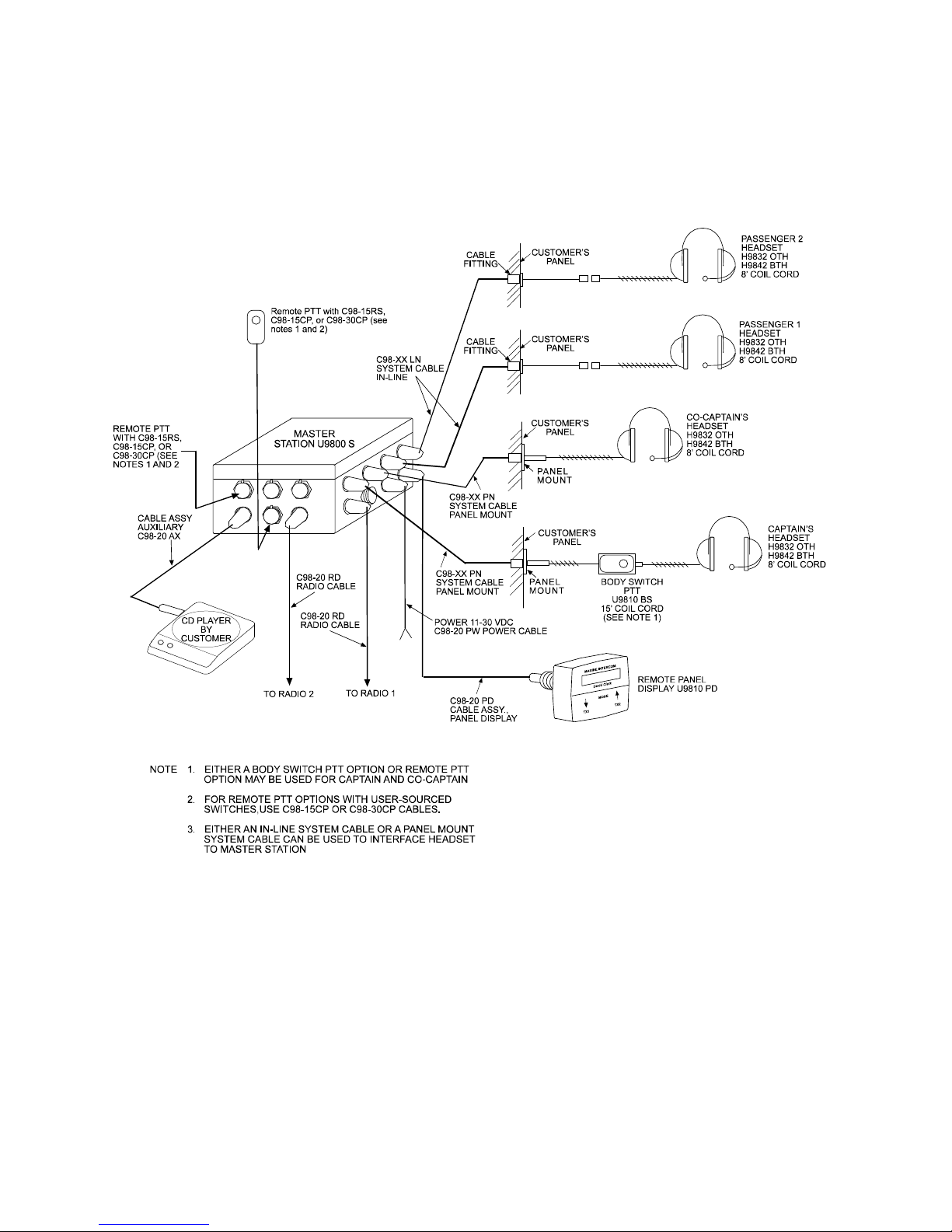
he Series 9800 Marine Intercom System is a weather-resistant communication system designed for the
marine environment. It allows a captain, co-captain, and up to four passengers (six positions total) to
communicate with each other over the intercom, and two of the members (captain and co-captain) to
communicate over two mobile radios. Also available is an option to interface a third audio source such as
a Stereo, CD player, or any other listen-only radio.
Primary components of the system are indicated in Table 1. In addition, a basic layout of a 4-position
system is shown in Figure 1.
Component Part and Model Numbers
Master Station
System Overview
aster Station - Model Number U9800S
M
Remote Panel Display
ontrol
C
Headsets (up to 6)
Cables
Panel Display - Model Number U9810PD
ver-the-Head Style – Model Number H9832
O
Behind-the-Head Style – Model Number H9842
Behind-the-Head Style – Model Number H9842BK
Behind-the-Head Style with Momentary Mic Switch – Model Number H9842SK
Note: H9842SK headsets are not recommended for Captain and Co-Captain positions.
Behind-the-Head Style with Throat Mic – Model Number H9842TM
n-Line System Cable (1 per headset)
I
10 foot Length – Model C98-10LN
15 foot Length – Model C98-15LN
20 foot Length – Model C98-20LN
25 foot Length – Model C98-25LN
30 foot Length – Model C98-30LN
50 foot Length – Model C98-50LN (connector unassembled for custom length)
Panel Mount System Cable (1 per headset)
10 foot Length – Model C98-10PN
20 foot Length – Model C98-20PN
30 foot Length – Model C98-30PN
Power Cable – Model Number C98-20PW (1 per master station)
Panel Display Cable – Model Number C98-20PD (1 per Panel Display, maximum of 1)
Captain’s Priority Cable – Model Number C98-15CP or C98-30CP (optional, maximum of 1)
Auxiliary Cable – M
Radio Cable – Model Number C98-20RD* (1 per Radio Input, maximum of 2)
* Other versions available. Contact factory with radio make and model.
emote PTT Switch - Model Number C98-15RS (Optional, Maximum of 2)
Remote PTT
Body Switches
1
9532P-62 (03-11)
R
Remote PTT Cable – Model Number C98-15CP or C98-30CP (Optional, Maximum of 2)
ody Switch, PTT, 15’ coil cord - Model Number U9810BS (1 per radio transmit headset,
B
maximum of 2)
Body Switch, PTT w/cell phone connector, 15’ coil cord - Model Number U9811BS
odel Number C98-20AX (1 per Aux input, maximum of 1 )
T
able 1: System Components
4 of 32
1
9532P-62 (03-11)
igure 1: Typical 4-Person Layout
F

5 of 32
1. Mounting the Master Station
P
arts/Tools Required
q U
9800S Series 9800 Intercom System Master Station (40898G-01)
q Master Station Mounting Kit (40688G-63)
o 4 neoprene washers
o 4 Stainless steel screws
o 4 Nylon washers
o 4 Stainless steel washers
o 4 Stainless steel nuts
q Pencil/Pen
q Drill
q 7/32-inch Drill Bit
q Drilling Template (Figure 3)
q Philips-head screwdriver
q 11/32-inch nut driver or wrench
Procedure
ocation Considerations
L
Select a location on a flat surface that is out-of-the-way, and provides adequate room to attach all
cables. Be sure to allow for internal access, as adjustments may be necessary. The Master
Station is weather resistant, however the mounting location should be chosen to minimize direct
exposure to the elements.
Mounting
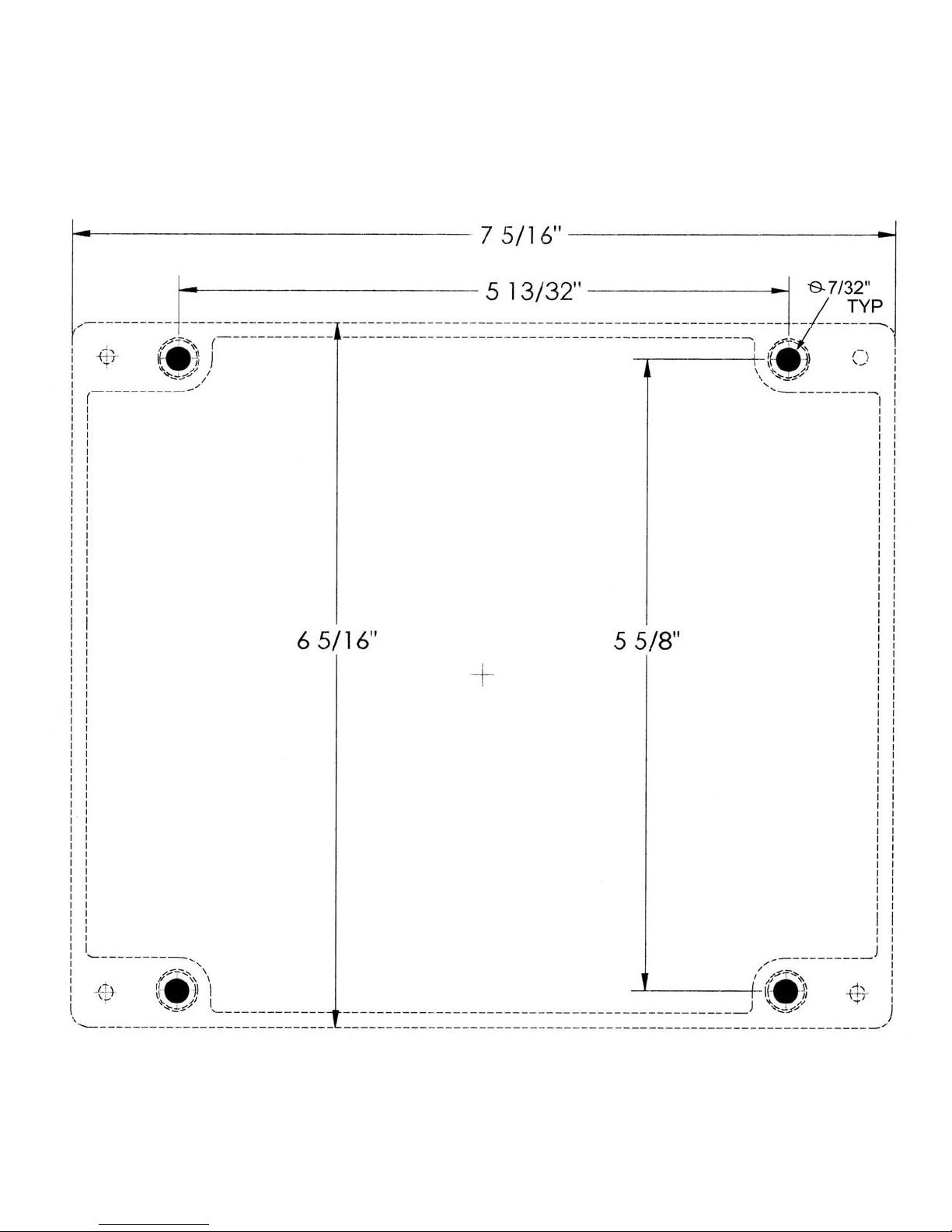
q Using the mounting template in Figure 3, mark and drill the (4) 7/32-inch holes through the
mounting surface.
q Remove the cover and position the Master Station on the mounting surface and confirm
mounting holes.
q Mount the Master Station using the hardware provided. Slide nylon washer over each screw
before using. Place a neoprene washer between the Master Station and the surface where
each screw is located. Use a stainless-steel washer on the back side of the surface under
each nut. Secure tightly with a stainless-steel lock-nut. See Figure 2.
q The installer may wish to leave the cover removed from the Master Station, as internal
adjustments may be necessary later during the installation. Be sure to replace cover and
tighten the four screws when adjustments are completed.
1
9532P-62 (03-11)

6 of 32
1
9532P-62 (03-11)
igure 2: Master Station mounting diagram
F
7 of 32
19532P-62 (03-11)
F
igure 3: Master Station Mounting Template

8 of 32
T
his Page Left Intentionally Blank
1
9532P-62 (03-11)
9 of 32
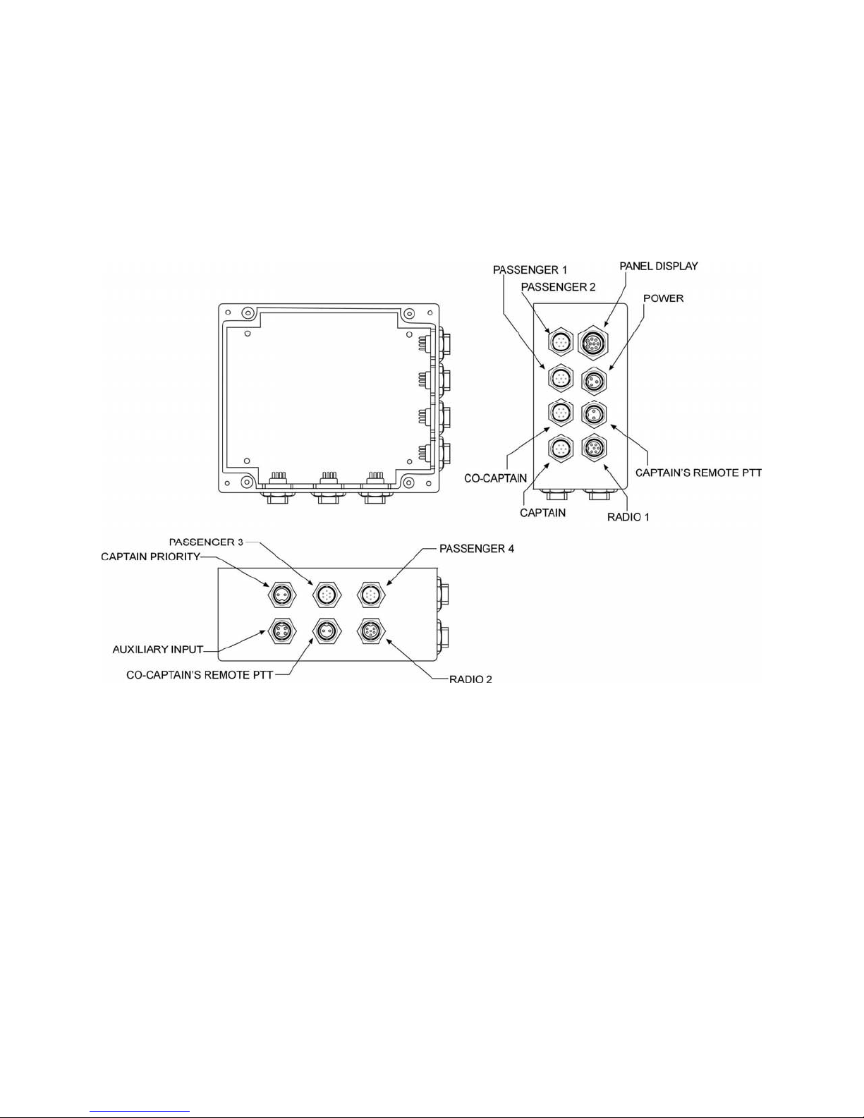
igure 4: Master Station Connections
F
1
9532P-62 (03-11)
 Loading...