


SETTING UP AND OPERATING INSTRUCTIONS
AND PARTS LIST FOR
DAVID BRADLEY
GARDEN TRACTOR
ROTARY SNOWPLOW
MODEL NUMBER
917.57587
The above number is the Model Number of your David
Bradley Garden Tractor Rotary Snowplow. It will be
found on a plate attached to the right rear corner of
the Scoop. Always mention the Model Number of your
Rotary Snowplow when communicating with us.
HOW TO ORDER REPAIR PAR TS
All parts listed herein may be ordered through Sears,
Roebuck and Co. or Simpsons-Sears Limited. When
ordering parts by mail from the mail order house
which serves the territory in which you live, selling
prices will be furnished on request or parts will be
shipped at prevailing prices and you will be billed
accordingly.
WHEN ORDERING REPAIR PARTS, ALWAYS GIVE
THE FOLLOWING INFORMATION AS SHOWN IN THIS
LIST:
1. The PART NUMBER.
2. The PART NAME.
3. The MODEL NUMBER.
4. The NAME of Implement.
This list is valuable. It will assure your being able
to obtain proper parts service at all times. We suggest you keep it with other valuable papers.
SEARS, ROEBUCK AND CO. U.S.A.
SIMPSONS-SEARS LIMITED CANADA
Printed in U.S.A.
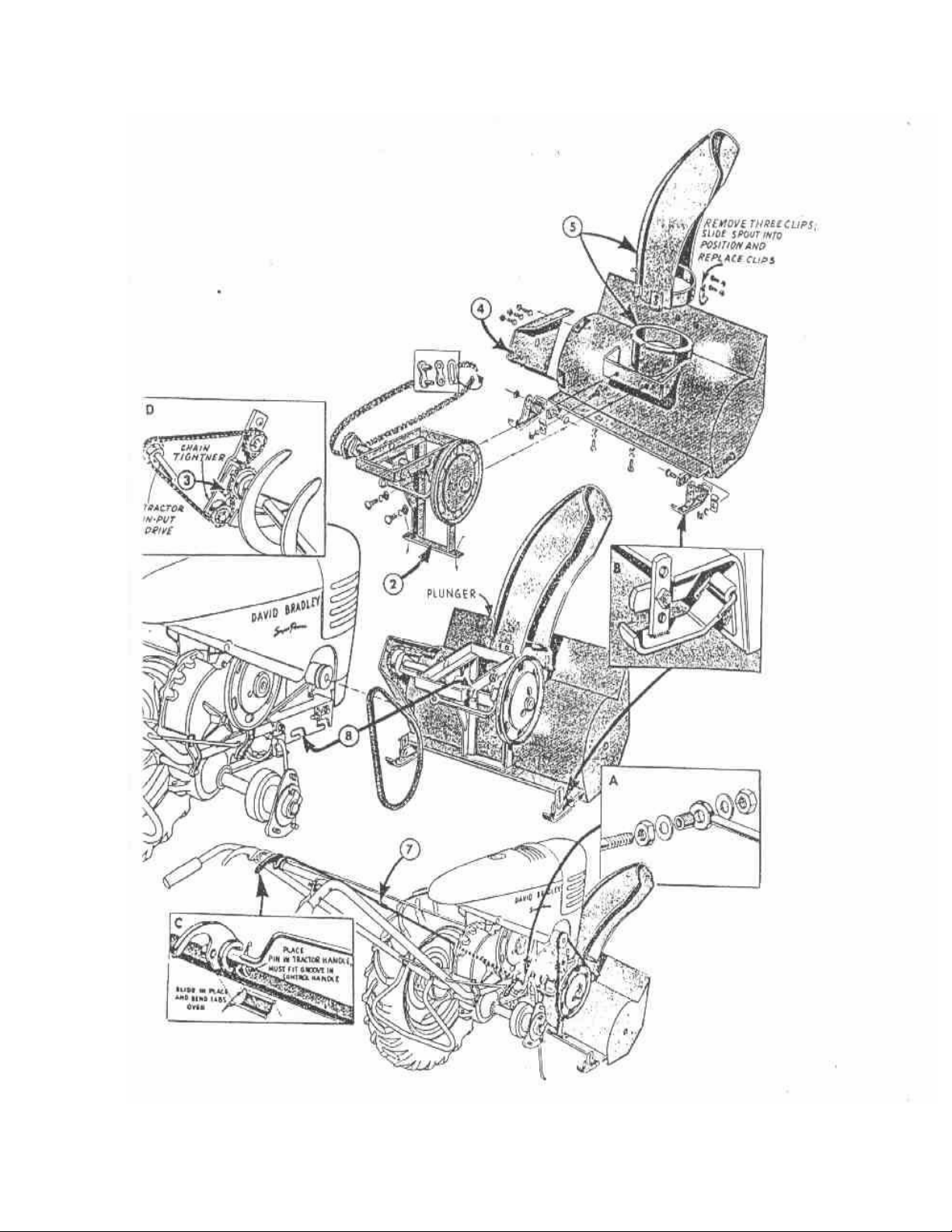
SETTING UP INSTRUCTIONS
FIGURE A
- 2 -

SETTING UP INSTRUCTIONS -- Continued
Setting-Up and Operating Instructions should be studied very closely before beginning to
assemble your Snowplow. A number at the beginning of a paragraph in the following instructions
refers to an arrow in the adjoining figure except when otherwise stated. When R.H. (Right
Hand) and L.H. (Left Hand) are used, it should be understood to mean from a position behind
and facing the Snowplow (or direction of travel).
Each Snowplow is given a thorough inspection before shipment, however, it is very important that it be again thoroughly checked at the time of receipt, to ascertain if any damage
has occurred in transit. A standard Snowplow shipment consists of the following package:
One Bundle Number 575x169 Rotary Snowplow
OPTIONAL EQUIPMENT
One Bundle Number 575x170 Slow Speed Pulley for any David Bradley Garden Tractor
equipped with Speed Changer.
One Bundle Number 575x171 Slow Speed Pulleys for Super Power and other David
Bradley Garden Tractors not equipped with Speed Changer.
INSTRUCTIONS FOR ASSEMBLING SNOWPLOW
Install slow speed pulley, (Bundle Number 575x170 or 575x171), per instructions furnished with pulley.
Remove the unit from the carton. Cut wires on scoop and remove the chainguard and mounting frame.
1. See inset B. Remove the two runners from the back side of the mounting frame and attach
them to the scoop with the clips at the rear of the scraping edge. The adjusting strap of
the runner attaches to the outer face of the runner support.
2. Attach the mounting frame to the scoop with four bolts as shown.
3. Refer to inset D. Install the roller chain on the sprockets as shown, and adjust until it
feels snug when depressed at the middle with the thumb. Lock this adjustment by tightening
the bolt through the two idler arms.
4. Attach the chain guard to scoop and bracket on drive shaft tube.
5. Attach the deflector to the discharge spout. To do this it is necessary to remove the guide
clips from the deflector so that it can be mounted with the spout extending up into the
deflector. After the deflector is in place, replace the guide clips so that they engage the
flange of the spout. Be sure that all clips are free on the flange of the spout so that it
will be easy to rotate the deflector.
6. Refer to inset C. Drive locator pin into handle spacer of tractor from the underside
until flush with underside of handle spacer. Mount control handle for snowplow on tractor
handle spacer and locating pin. Slip control handle retainer in from the right and bend
the tabs down to hold it in place.
7. Assemble clutch control rod and secure with coupling pin in intermost hole of the upper
control rod.
INSTRUCTIONS FOR ASSEMBLING SNOWPLOW TO TRACTOR
8. Loosen nuts on welded mounting bolts. Slide snowplow into position on motor base plate.
Place belt on clutch and motor pulley and adjust belt by sliding snowplow forward. Proper
adjustment of belt is 1/4 inch sag with a slight thumb pressure on belt. Tighten nuts securely on belt side of mounting frame and then on opposite side. These nuts must be kept
tight to prevent belt from slipping.
9. Inset C. Attach clutch control rod to control handle on tractor handle.
10. Inset A.Remove the outer nut and washer from the control rod. CAUTION: Do not remove the
spacer or inner washer from the control rod. Insert the control rod and spacer in the
clutch yoke arm. Replace the outer washer and nut. NOTE: Adjustment of the clutch is controlled by these nuts and washers. Do not turn the outer nut on rod more than flush with
the end of the rod until you have read the section of this manual on the adjustment of the
clutch, page 5.
- 3 -

OPERATING INSTRUCTIONS
Although this Snowplow is simple to operate and care for it is important that instructions, as outlined in this manual, be studied and followed very closely. Only by following
these suggestions can satisfactory performance and long service be obtained. We suggest that
you keep this manual for future reference.
INSTRUCTIONS BEFORE OPERATING
Wax the inside of the deflector and spout with a hard auto wax, (Allstate or any other
good wax). This will let the snow slide easier.
CAUTION: Be careful not to direct the snow towards windows or persons since small rocks
which can be picked up by the impeller could cause damage or injury.
Be sure to clean all snow and ice from around the chain and sprockets after each use to
prevent them from becoming frozen fast.
Keep all bolts and nuts tightened securely.
CAUTION: KEEP HANDS AWAY FROM IMPELLER, DRIVE BELT AND CHAIN WHILE ENGINE IS RUNNING.
LUBRICATION
EVERY HOUR Drive Shaft (figure C, Illust. 27) 1 place 2 shots grease
Idler Sprockets (figure C, Illust. 46) 2 places 2 shots grease
EACH SEASON Impeller and Clutch Pulley -- Use Allstate or any other
good grade of SAE 20 motor oil.
OPERATING SPEED
The Impeller should be operated at full speed at all times. A partial swath may be taken
in difficult conditons if necessary to maintain the impeller speed. For best performance it is
desirable to keep the volume of snow being handled at a maximum and still not pull the speed
of the engine down.
HEIGHT OF CUT
On smooth sidewalks and concrete driveways the runners can be set in the lowermost hole
so that the scoop will scrape the walk. On gravel drives or rough sidewalks, the runners
should be set in the center hole so that the scoop will not catch on obstructions. Under very
adverse conditions it may be necessary to set the runners in the uppermost hole on the adjusting strap. (See Figure A, Inset B).
DEFLECTOR
The deflector can be positioned to throw the snow to either the right or left or at an
angle of 45 degrees forward of the right or left. This is accomplished by pulling up on the
plunger, figure A, on the rear of the deflector and rotating it to the desired position. At
this point the plunger is released to engage a notch in the flange of the spout to hold the
deflector in that position.
DRIVE BELT
Keep enough tension on the belt to avoid slippage under normal loads. This will be
equivalent to 1/4 inch sag with a slight thumb pressure on the belt midway between the
sheaves.
CHAIN
Keep roller chain tight enough to avoid any noticeable sag in either strand when the
impeller is at rest. To tighten, loosen the bolt which goes through the upper and lower idler
arms and push the lower idler arm down while oscillating the impeller. When the lower idler
arm is down as far as possible, tighten securely with the bolt through the idler arms. Refer
to figure A, inset D, Illustration number 3.
- 4 -
MAINTENANCE AND SERVICE INSTRUCTIONS
CLUTCH
FIGURE B
The clutch of the Rotary Snowplow is a double plate friction type mounted directly on
the drive shaft. With average use and care it will last indefinitely. However, extreme roughness, exposure, and carelessness, will result in damage, therefore, the following instructions
are given for adjustment and repair.
ADJUSTMENT
Adjustment of the clutch is controlled by two nuts and two washers, one each on either
side of the spacer on the clutch control rod, Figure C, Illustrations 51 and 55. With the
clutch control lever in the disengaged position turn the adjusting nuts, Figure C, Illustration 37, on to the control rod far enough to release the clutch. The throwout lever, Figure B,
Illustration 51, should float between the two washers on the spacer when the control rod is in
the engaged position. The action of this clutch is approximately 3/64 of an inch. Each time
the Snowplow is removed and reattached to the tractor or if the drive belt is adjusted for
tension, the clutch must be readjusted. When using the tractor for belt work with the Snowplow
attached remove the drive belt.
CAUTION: Keep clutch adjusted properly to prevent Snowplow from slipping into gear. Keep
hands away from impeller, drive belt and chain, while engine is running.
After the Snowplow has been in operation for some time, the clutch facings, Figure B,
Illustration 43, may become glazed or covered with grease and oil causing slippage. To repair,
remove the facings (See instructions for removing as given under the Replacement and Repairs
Section of this Manual), and in the event of glazing, a good wire brushing, applied to the
facings will break up the glaze and restore normal operation. In the event a covering of
grease or oil causes the slippage, wash the facings in gasoline or kerosene and wipe dry. If
this does not correct condition, clutch facings should be replaced.
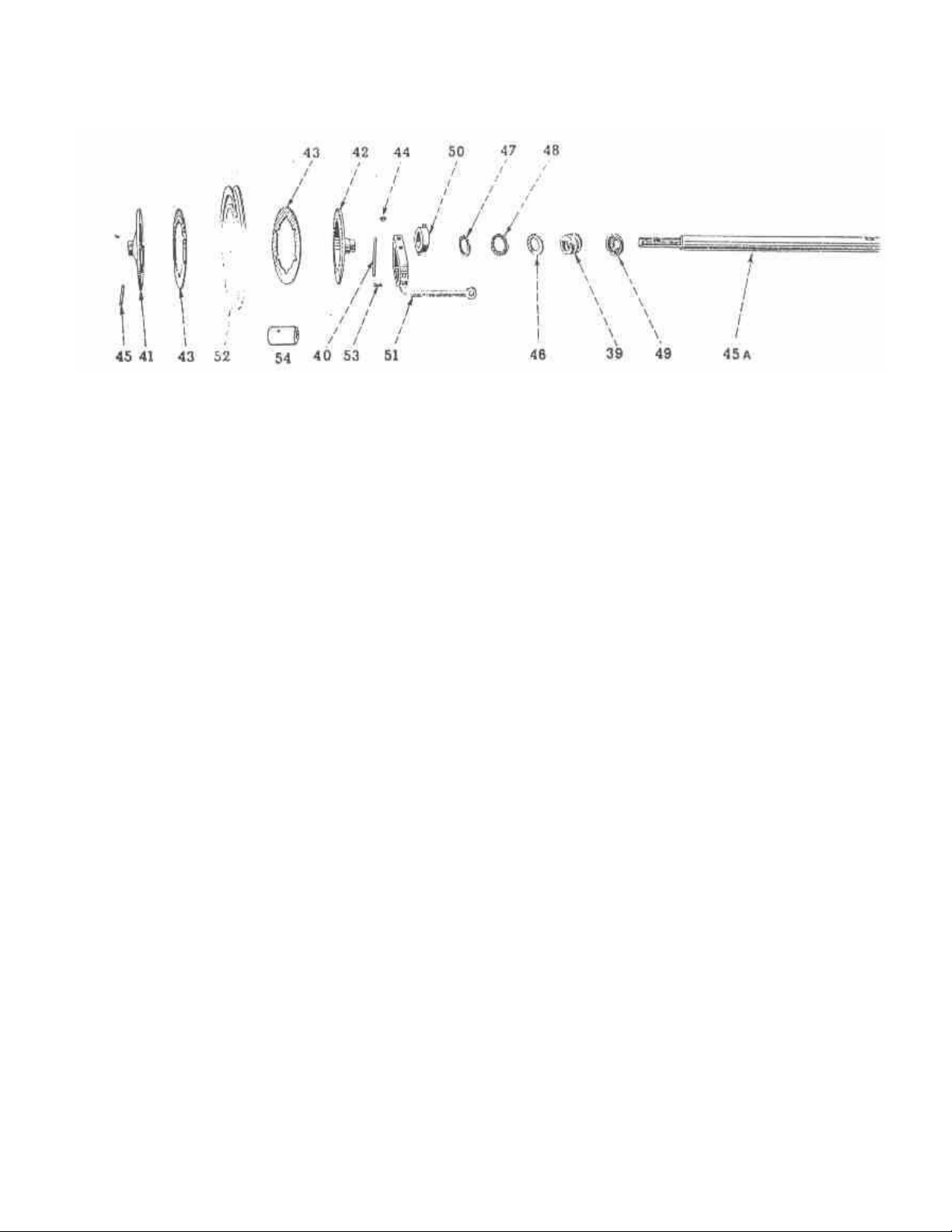
REPLACEMENT AND REPAIR
The following Illustration Numbers refer to Figure B unless otherwise stated.
FACINGS
To replace facings:
1. Disengage clutch.
2. Remove groove pin, Illustration 45.
3. Remove outer Clutch Plate, Illustration 41, Facing Illustration 43, and Pulley,
Illustration 52 by sliding from shaft.
4. Remove all burrs from the shaft.
5. Thoroughly clean all parts of grease and oil.
6. Using new facings, reverse the above procedure to assemble.
Maintenace and Service Instructions Continued on Page 8.
- 5 -

PARTS LIST
Bolts, Nuts, Washers, Cotter Pins, etc. of standard dimensions do not
carry part numbers. When these standard items are needed in service
they should be purchased at the nearest Sears Roebuck and Co. or
Simpsons-Sears limited store or from a Local Hardware Store.
Each part has been given an illustration number which is used only as a key to find the
part number . Do not use the illustration number when ordering repair parts.
FIGURE C
- 6 -

PARTS LIST
Illustration
Number
Qty.
Req’d.
Part
Number
Description
1 1 102M Woodruff Key
2 1 1919U Spring
3 1 4285M Control Handle Retainer
4 1 4290M Control Handle
5 1 4306M Drilled Right HandRivet
6 1 4309M Inner Clutch Plate
7 1 4316M Pulley Bearing
8 1 9787M V- Belt
9 1 4325M Hypro Key
10 1 4589M Upper Control Rod
11 1 4597M Control Rod Coupling
12 1 4664M Inner Clutch Washer
13 1 4665M Outer Clutch Washer
14 1 4666M Clutch Throwout Clutch
Bearing
15 2 4672M Shoe Hinge Bracket
16 1 4865M Groove Pin
17 1 4866M Outer Clutch Plate
18 1 4938M Retainer Spring
19 1 5558A Bushing
20 2 6272M Clutch Facing
21 3 6855M Grease Fitting
22 1 7836M Roll Pin
23 2 8015M Bearing
24 1 8084M Roll Pin
25 1 9571M Plunger
26 1 9572M Impeller Support Shaft
27 1 9574M Drive Shaft
28 1 9592M Chain Guard
29 4 9596M Guide Clip
30 1 9597M Reinforcement Band
31 1 9607M Spring
32 2 9608M Bearing
33 2 9609M Bearing
34 1 9615M Connecting Link,Complete
35 1 575PA23 Clutch Spring Case & Washer
36 1 575PA28 Clutch Throwout Cup & Pins
37 1 575PA46 Clutch Throwout Lever &
Yoke
38 1 575PA63 Lower Control Rod with
Sleeve
Illustration
Number
Qty.
Req’d.
Part
Number
Description
39 1 575PA215 Pulley and Bearing (Casting
No. 6271M1)
40 2 575PA466 Runner and Brackets
41 1 575PA472 Scoop
42 1 575PA473 Idler Arm & Stud - Upper
43 1 575PA474 Idler Arm & Stud - Lower
44 1 575PA475 Reinforcement & Runner
Supports
45 1 575PA478 Deflector and Plunger Guide
46 2 575PA479 Idler Sprocket & Bearing
47 1 575PA480 Attaching Frame & Bearings
48 1 575PA481 Impeller & Bearings
49 1 575PA482 Roller Chain (includes con-
necting link 9615M)
50 1 575PA483 Drive Sprocket with Set Screw
51 2 Nut, Hex 5/16”-18 N.C.
52 1 Allen Set Screw C.P. 5/16”x
5/8”-18 N.C.
53 1 Washer, Flat 9/32”x5/8”-16
G.A.
54 4 Washer, Flat 21/32”x
1-5/16”-13 G.A.
55 2 Washer, Flat 3/8”x7/8”-
14 G.A.
56 2 Cotter 3/32”x1/2”
57 3 Cotter 3/16”X1”
58 8 Bolt, Square Net Carriage
1/4”x3/4”-20 N.C. with Nut
and Lock Washer
59 1 Bolt, Square Net Carriage
3/8”x1-1/4”-16 N.C. with
Nut and Lock Washer
60 9 Bolt, Square Net Carriage
3/8”x1”-16 N.C. with Nut
and Lock Washer
61 4 Bolt, Square Net Carriage
3/8”x3/4”-16 N.c. with Nut
and Lock Washer
62 2 Bolt, Square Net Carriage
5/16”x3/4”-18 N.C. with
Nut and Lock Washer
63 3 Bolt, Square Head Machine
5/6”x3/4”-18 N.C. with
Nut and Lock Washer
64 4 4811M Flanged Square Nut
- 7 -

MAINTENANCE AND SERVICE -- Continued
REPLACEMENT AND REPAIRS, Continued
The following Illustration Numbers refer to Figure B unless otherwise stated.
Be sure to replace the pulley with the oil hole to the outside. In the event new parts
other than facings are reqauired be very sure that each part slips freely over the drive
shaft. These parts are precision made and MUST slide freely. DO NOT FORCE.
PULLEY BEARING
1. In the event the bronze bearing, Illustration 54, in the clutch pulley, Illustration 52,
should need replacing: align the new beraring against the old one. Drive out old bearing
using a soft wood block.
THRUST BEARINGS
To replace Thrust Bearing:
1. Remove facing, using same procedure as outlined under Facings.
2. Slowly engage clutch conjtrol rod which will allow the clutch throwout cup, Illustration 50,
to slide away from the clutch spring case.
3. Remove nut from end of clutch control rod, Figure C, Illustration 51, being careful not to
lose washer or spacer.
4. Remove ontrol rod from throwout lever and yoke, Illustration 51, by placing clutch control
rod in disengaged posxition.
5. Remove pin, Illustration 40, from throwout lever and yhoke, Illustration 51.
6. Remove inner plate, throwout cup, thrust bearing, inner washer, outer washer, ahnd spring by
slikdinhg partgs from drive shaft, Illustration 45A. (Note, --When replacing thrust bearing
it is usually desirable to also replace inner and outer washer).
7. To reassemble, first check all new parts to be sure each part fits properly on the drive
shaft and hypro key.
8. Assemble outer washer, Illustration 47, and thrust bearing, Illustration 48, in the clutch
thowout cup, Illustration 50.
9. Place an amount of universal joint fiber grease (equal in size to that of the eraser on an
ordinary lead pencil) in the area around the thrust bearingv.
10.Insert inner washer, Illustration 46, in place against thrust bearing.
11.Insert spring, Illustration 39, in clutch spring case, Ilustration 49, and place clutch
throwout cup in position against spring,km Illustration 39. Then drop in, Illustration 40,
in place through throwout lever yoke, Illustration 51.
12.Position inner clutch plate, Illustratio 42, by placing right hand on clutch throwout cup
and yoke, moving it about until inner clutch plate slides into place on hypro key.
13.Replace clutch control rod in throwout levcer and yoke and tighten lower nut against washer
and spacer.
14.Disengage clutch lever which will allow pulley, facings, and outer plate to be set in
place.
15.Drive groove pin in place.
16.Check clutch adjustment and readjust if necessary. (See adjustment).
STORAGE
When storing the machine for any length of time, especially during the summer, be sure
to coat the roller chain thoroughly with a good grade of oil to prevent it’s rusting and
bvecoming stiff. Also, apply a light coatg of oil to the interior of the scoop and deflector
to keep them from rusting.
All bearings on this machine are replaceable.
IMPORTANT SUGGESTIONS
CAUTION: Be careful not to direct the snow towards windows or persons since small rocks
which can be picked up by the impeller could cause damage or injury.
Be sure to clean all snow and ice from around the chain and sprockets after each use to
prevent them from freezing fast.
Keep all bolts and nuts securely tightened.
CAUTION: KEEP HANDS AWAY FROM IMPELLER, DRIVE BELT AND CHAIN WHILE ENGINE IS RUNNING.
Sears Roebuck and Co. and Simpsons-Sears Limited reserves the right to make any changes
in design and changes or improvements on implements without imposing any obligation to install
the same upon its implements heretofore manufactured.
- 8 -
 Loading...