

Page 1
I Sears I
owners
manual
/
MODEL.NO.
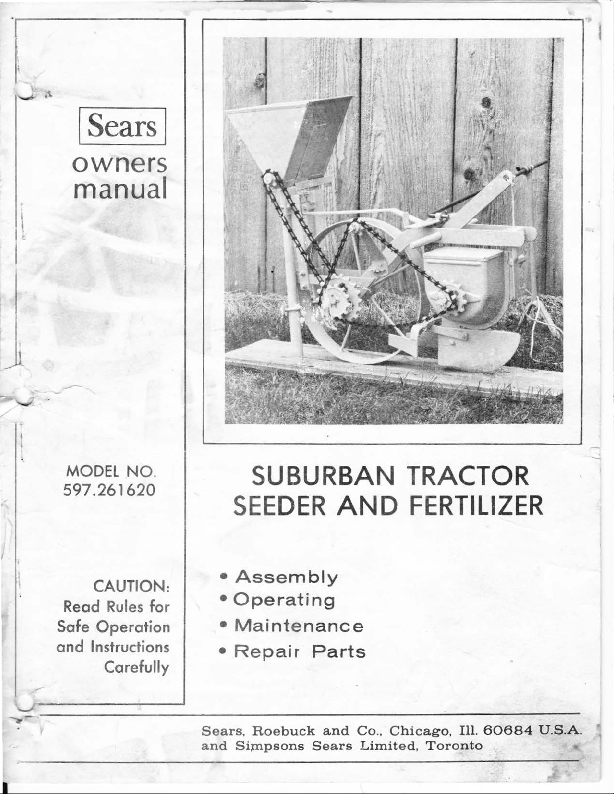
SUBURBAN TRACTOR
597.261620
SEE
•
CAUTION:
Read
Safe
and
~----------------------
Rules
Operation
Instructions
Carefully
for
Sears,
and
Asse
•
Operating
•
Mainten
•
Repair
Simpsons
DER
mbly
---------------------------
Roebuck
AND
ance
Parts
and
Sears
Co.,
Chicago
Limited,
FERTILIZER
,
Ill.
60684
Toronto
U.S.A
.
Page 2
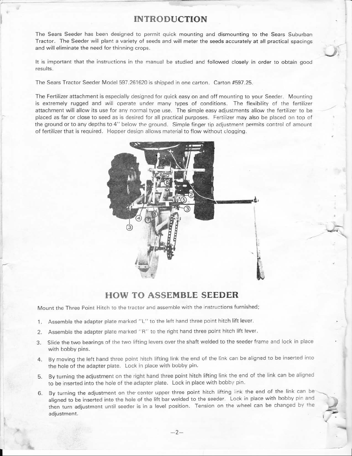
INTRODUCTION
The Sears Seeder has been designed
Tractor. The
and
will eliminate the need
It
is
important
results.
Sears Tractor Seeder
The
The Fertilizer
is
extremely rugged and will operate under
attachment
placed as far
the
ground
of
fertilizer
Seeder will
that
attachment
will
allow its use
or
close
or
to
any
that
is required. Hopper design allows material
plant
a variety
for
thinning crops.
the instructions in
Mod
el597.261620 is shipped in one carton. Carto n #597.25.
is especially designed
for
to
seed
as
depths
to
4"
to
the
any normal
is
desired
below
permit
of
for
the
quick
mounting
seeds and will meter
manual be studied and followed closely in order
for
quick
easy on and o
many
type
all practical purposes. Fertilizer may also be placed
ground
types
use. The simple easy adjustments allow the fertilizer
. Simple finger tip adjustment permits control
to
and dismounting
the
seeds accurately
ff
mounting
of
conditions. The flexibility
flow
without
clogging.
to your Seeder.
to
at
the
Sears Suburban
all practical spacings
to
obtain
of
the fertilizer
good
Mounting
to
on
top
of
amount
be
of
HOW
Mount
1.
2. Assemble the adapter plate marked
3.
4.
5. By
6.
I
the
Three Point Hitch
Assemble the adapter plate marked
Slide the
with
By
the hole
to
By
aligned
then
adjustment
two
bearings
bobby
moving the
turning
be
turning the adjustment
pins.
left
of
the adapter plate.
the adjustment
inserted
turn
into
to
be inserted
adjustment until seeder is in a level position. Tension
.
of
hand three
the hole
into
TO ASSEMBLE
to
the
tractor
the
two
point
Lock
on
the right hand three
of
the
on
the- center upper three
the
hole
and assemble
"L"
to
"R"
to
lifting
levers over the shaft welded
hitch lifting link the end
in place
adapter plate. Lock in place
of
the
SEEDER
with
the ins
tructions
the left hand three point hitch
the right hand three point hitch lift lever.
of
the
with
bobby pin.
point
hitch lifting link the end
with
point
hitch lifting ;ink
lift
bar welded
to
the seeder. Lock in place
-2-
furnished;
lift
lever.
to
the seeder frame and lock in place
link can
bobb
on
be
y pin.
the
the
wheel can be changed
aligned
of
to
be inserted
the link can be aligned
end
of
the
link can be
with
bobby pin and
by
into
the
t
~
-
Page 3
7.
When
seeder is in use
th
e back Hopper Brack
to
the
bracket
of
end
(2) holes located in the rear
the Moun
rear
ting
without Fertilizer Attachment,
et
(bracket closest
of
the Seeder. The stops
Bracket. Secure the Marker Bracket
hopp
er bracket.
to
wheel)
of
the Mounting Bracket are the two welded angles on each
mount
the Marker Mounting Bracket
of
the Seeder, keeping the stops on the marker
with
th&
two
(2) bolts provided, using the
to
the top
of
two
8. The bent end
t.
bracke
will rest in
Rod
9.
When
the Fertilizer
the instructions provided
and the
with
Fertilizer. The washers are used
bracket and the Marker
of
the marker rod is inserted
This rod should be inserted
front
of
Attachment
two
bolts
which
HOW
(A) -
To
Assemble Fertilizer
1. Remove U Bolts (#8020).
2.
Attach
tighten
which
Now
mounting bracket
nut
too
securely. Then pldce this assembly in position
extend
fasten securely
down
from
with
into
the bushing
from
the rear
the stops
with
are provided
Mounting
Attachm
(#F801
the fertilizer mounting bracket on the outside
2 bolts the T
of
the marker bracket.
is being used
the Fertilizer. The Fertilizer bracket is mounted under the marker bracket
with
as
bracket.
TO
ASS
ent
and
3)
to
fertilizer bracket assembly
with
the Seeder the Fertilizer is mounted in accordance
the marker bracket are used in place
spacers and are placed on each
EMBLE FERTILIZER
Mount
End
on Seeder:
of
Mounting Bracket Part (#F8013)
of
the Mark
which
is located in the center
er
as
of
the mounting
Mounting Bracket so that the
of
two
bolts which come
of
the bolts between the Fertilizer
(#F
8007)
as
shown in Fig. A. Do
shown in Fig. B, keeping the
of
Seeder rear scraper bracket.
to
the bracket on Seeder.
Mar
two
ker
with
not
bars
3.
Replace U bolts (#8020) see Fig.
of
side braces will be flush
(#8020).
Bolts.
4.
Now
tighten nut under instruction #2 above so
assembly
5. Remove cotter key (opposite fro m sprocket) on
remove
original position. Replace cotter key being sure cotter key is
retighten the set screw on rear wheel hub. Do
6.
Loosen the
(#F8001) in place
7.
Place chain (#F8021) over both sprockets (#F8025 - #F8006). Line
axle
8. Raise fertilizer body assembly (#F8001) keeping same level until slack is removed from chain
tighten the
9. Loosen U Bolts (#8016) enough
feed tubes until they meet
Fertilizer attachment is
(#F8007) are secure.
axle shaft from seeder. Place sprocket
two
top nuts on
as
shown in
with
the sprocket (#F8006) on fertilizer shaft, then tighten the set screw on sprocket
two
nuts
which hold fertilizer body in place. CAUTION: Do
now
ready
with
with
B,
bring side braces
the back
the
Fig. A.
to
bot
for
use.
side
of
fertilizer mounting bracket (#F8007). Place fertilizer body assembly
Do
not
fasten nuts yet.
permit feed tubes (#8015) to be inserted thru U bolts. See Fig. B, raise
tom
of
fertilizer body and then tighten nuts on U bolts .
which
Seeder scraper bracket. While in this positi on tighten U
that
Seeder axle shaft, loosen set screw in wheel hub and then
(#F8025)
not
fasten set screw on sprocket (#F8025) yet.
hold U Bolts (#8020) backwards so the edge
mounting bracket (#F8013) and fertilizer bracket
on
axle shaft and then replace shaft back to its
up
against rear axle bearing and then
up
the sprocket (#F80
(#F802
not
overtighten chain.
25)
on Seeder
5).
(#F
8021) and
,..
-3-
Page 4
SEEDER OPERATING INSTRUCTIONS
The ground intended
and should be
The depth
means
obtained by loosening the set screw on the hopper shoe and then raising
Row coverers, (illustration
hold them in place, the angles
as
Each sprocket is numbered according
- i.e.,
spro cket chain.
For best results
page 9. The chart is intended as a general guide and is
shape and size.
tests.
two
your hand in a vertical position and hold in the same hand a flat piec e
of
the one pocket
backing and see
determine whether the seed disc pocket is too small
desired.
repeat the test until the proper disc is found.
of
desired.
In
or
more seeds at a time.
the disc where the pocket breaks through. Place the number
well leveled by raking
of
planting is first determined and then adjusted by raising or lowering the seed hopper unit by
loosening the
it
will
go
some cases one seed at a
If
the disc you tested does
to
be planted should be properly prepared and should be
or
rolling.
two
wing nuts
#26
and #27) are furnished,
of
the coverers may be changed, which will
on either wheel
it
is important
It
is recommended
of
the seed disc and
if
the seed will fall through the pocket. By following this procedure you will
or
to
select the ·proper seed disc.
time
To
select the correct disc, choose one that appears
which
to
the number
hopper shaft and will
that
the proper disc
is desired
see
if
the pocket will hold the seed
not
suit, select the next size larger
hold the hopper in place. Additional adjustment may be
which
of
teeth on it, and
go
not
always the
for
for
planting, while in other cases,
or
too
are adjustable. By loosening th e bolts
on either
To
help in selecting the disc refer to chart on
each purpose can
of
of
seeds you wish to
large
to
permit the plant'ng
of
a fine texture, free
or
lowering the shoe.
put
more
or
less dirt on the seeds
1s
both interchangable and reversible
way
which
allows proper alignment
most
accurate, srnce seeds
be
selected by a few simple
it
may
to
be correct, hold same in
steel
or
wood
backed against the side
be
or
seeds. Remove the
or
smaller
as
the test ·ndicates and
be
planted together ir,
of
desired
wood
seed
w1ll
be
or
of
trash,
which
vary in
to
plant
or
steel
able
seeds
of
to
as
with
When filling the seed hopper
in the hopper. Remove the hopper by loosening the
of
the slots
The
compartment. Adjust the
sowing a
and inserting the seeds directly
To
remove seed disc from hopper, take hold
compressing
disc, release hold on hopper shaft and revolve shaft which
disc.
The brush assembly is used
recommend its
Do
not
becomes clogged.
the seeder brackets. The hopper is easily cleaned by turning same upside down.
flow
control disc is used
flow
small quantity
the
clutch spring, which releases the seed disc
use
permit tractor
of
small seed
only
with
to
go backwards while planting shoe is engaged
any particular type
to
regulate the
control disc by rotating until the desired opening is obtained. Note: When
s,
better results are obtained by completely closing the
into
the sowing compartment.
to
rnsure positive ejection
the A and B disc.
of
seed, always make certain that there are
two
flow
of
of
the outer end
of
small seeds.
seeds from the targe compartment
no
lelt
overs
wing nuts and then slipping the wing nuts through
to
the sowing
flow-cont
of
the hopper shaft and pull outward thus
for
removal
will automatically engage seed disc
or
insertion.
It
1s
easily removed
with
the soil,
After
insertrng required
•r
replaced and
as
this wili cause shoes
with
rol disc
the drive
we
to
- 4-
Page 5

FERTILIZER OPERATING INSTR UCTIONS
1. To adj
2.
3.
4.
5.
ust
for the desired spacing
tubes
to
be sprea
To
place fertiliz
lower openers
Be
fore filling the hopper
(Shut
feed.
Fertilizer in
adjustment gauge
openings, each
NOTE: Fertilizer is fed when agitators are moving and
sprockets and agitatiors are
d apa
rt
to the desired position , then retighten the U bolts.
er
at
desired depth loosen t
to
obtain desired location and th
with
off
position so that fertilizer will not feed).
now
loaded into the hopper.
into
the
desired notch. There are 5 notches which permit a closing and 4 differe nt si
of
the notches regulating different amounts of fertilizer
tight
of
fertilizer loosen U bolt
he
nuts on U blots which are welded
en
retighten nuts. Position the openers
fertilizer pull Feed Adjustment gauge (#8010)
To
adjust
for
the requi
to
prevent any
of
these parts from slipping on shafts.
DESIGN FEATURES
The Seeder
seeds. The
beans.
For continuous-row,
disc are
discs are available.
hopper and deliver the seed through
ground tube and
accurate spacing between seed dropping regardless
stops made in crossing the field. This method will plant seeds
is
designed
large selection
of
a different size, corresponding to
to
handle every variety
of
various size seed ?iscs will permit
or
drill seeding any one
As
the disc turns,
out
through the opening shoe into the soil. This positive-feed method assures uniform,
of
practical problem that may confront the planter of garden
of
the
the
size
the
pockets on the disc pick the seeds
the
opening in the side
7 twelve-pocket seed discs is used. The pockets
of
the seed required. For hill seeding, four 2 pocket
of
how
s holding feed tubes enough
to
openers, then rai
out
to
the
red
amount
it
is important that the set screws on both
the
planting
of
the hopper, allowing them
fast the seeder
without
injuring the seeds.
of
fertilizer desired move feed
to
be fed.
of
every type seed
up
is
operated,
from the
to
per
as
in
photo
last notch
from
bottom
to
fall through
or the
number
mit feed
se
B.
of
finger
lettuce
of
each
seed
of
or
ze
to
the
the
of
hill seeding where one
For
it
the planting
m
furnished
full and adequate selection
A
Depending upon
combinations may
disc 7 more combinations are
practical spacings. Each combination sprocket is made in one solid piece, therefore, there are no
sprockets
wheel is fitted
The
difficult.
The seed hopper is instantly removable, so that any
to
a different type seed. Depth
ope
ning-plow
saving
A pair
coverage
operated.
The Marker Assembly is provided so that the desired spacing
of
time and labor
of
adjustable
of
one
as
standard equipment. The F-2, E-2, and
which
be
to
get mislaid
insures sowing in a straight, narrow row, which permits close cultivation and a considerable
of
dirt
over
or
more seeds will be required in each hill, four-2 pocket discs are used, which per -
or
more seeds in each hill
of
seed spacing is provided through the
of
the
shafts each sprocket is placed on, and on which
selected. By using a
available. The total
or
lost, since
with
a scraper
by
elimination
row
coverers is furnished
the
seed regardless
both
to
of
planting is regulated by a quick simple adjustment. The design
at
intervals
J-2
12
pocket disc 7 combinations
of
combination sprockets are always in use on the seeder.
keep
the
soil from sticking
left
of
thinning and a great reduction in
which
can
of
the
uneveness
of
16 -24 -36
discs are available
14
combinations will make
over seeds can be easily emptied
be
adjusted
of
the ground over which the seeder is being
bet~en
- 48 -
or
72 inches. The G-2 disc is
by
special order.
use
of
the
two
combinations sprockets.
way
it
is
are
possible.
to
it
and making operation clumsy and
the
amount
to
each individu
rows can be maintained when pla
By
it
possible
of
al
need
placed any one
using the 2 pocket
to
plant at all
out
when changing
weeding necessary.
to
insure proper
of
"spare"
of
the
nting.
7
The extension clamp is provided
by
inserting the Marker Collar between
marker
To change the marker
I
collar. Secure
thumb
for
use
screw on marker collar when desired position is found.
from
to
permit adjusting
the
eyes
one side
to
to
various desired spacings. The Marker is held in place
of
the Marker and sliding
the other side, swing the marker rod
the
marker rod through the eyes and
-5-
with
the
rope.
Page 6

SEARSSUBURBANTRACTORSEEDER
.-----------------------------------,
I I
37
I
I
I
I
I
FIGURES 3 AND
- 6-
3A
CUTAWAY
SE
E.D
HOPPER
0~
Page 7

SEARS
SUBURBAN
TRACTOR
SEE
DER
PARTS
LIST
Ill
us.
No.
1 1#17034R
2
3
4 1#17117
5
6 1#10000 5/ 16 7
8 1#17019
9
10
ll
12
13
14
15 1#17062
16
17
18
19
20
21
Part
No.
Hl7112B
1#17093
Hl7182B
1#17081
#10001
1#17046 Re
#17045
#17018
1#170
55
1117092
1117058
Ill
70
61
11
17102
ff170b3
1117064
1#17020Al2
lll7020Bl2
II17020Cl2
1#17020D12 5/16
1#17020El2
1#17020Fl2
lll7020Gl2
Part
Name
Cha&,sis Ass
Concave Rear Wheel
Rear Scraper
C
oncave Wheel Scraper
Idler L
Id
ler
Spr
Lar
ge
1
2T-l
Spr
ocket
Link
Be
ar
Axle
Rear Wheel Bushings
Sma
ll
Double
6T - 1
2T
H
opper
Hop
pe r
Assembly
Fl
ow
Control
Spr
in g
Hop
per
W
asher
Flow
Brush
D
Dr
1
3/16 Diam. Pocket
1/4 Diam. Pocke
3/ 8
1
9/16 Diam.
Control
Assembly
riving
ivi
ng
/8
Diam.
(12 Pocket
(
12
Pocket Seed Disc)
(12 Pocket
Diam.
(12
Pocket
Diam.
(1
2 P
/2
Diam. Pock
(12 P
(12
Pocket
embly
Bracket
ever
Ass
embly
18
Wing
ocket
Double
8T
Cha
1t 45
Shaft
Sleeve
Flow
D1sc
Disc Assembly
ocket Seed
ocket Seed
Nut
6T
Sprocket
in
1125
Links
Sprocket
Di
sc
Disc
Dis
c
Sp r
ing
P o
cke
t
Seed
t
Seed
Pocket
Seed Disc)
Pocket
et
Poc
ket
Seed Disc)
Disc)
Disc)
Disc)
Disc)
Ill
us.
No. No.
22
23
24
.
25
26
27
28
29
30
31 1#17024
32
33 1#17078H
34
--="'
35
36
37 1#17313
Part
·
lll7020E
1#17020F 2
1#17020G 2
1#17020J 2 3/4
1#17097
1#17094
#17060
1#18093
1#18090
1#18089
1#18091
#fl7303A
1#17302A
1#17025R
1#17310
1#17311
1#17312
3/8
2
1/2
9/16
Hopper
5/16-
Hopper
Hopp
L.
R. H.
Coverer
L.H.
R.H.
Marker
Marker
Marker
Marker
Marker
tviarker
Complete
(2
(2
(2
(2
Assembly
Assembly
Assembly
Assembly
Part
Name
Diam.
Pocket
Diam.
Pocket
Diam.
Pocket
Diam.
Pocket
Cover
18
Wing
Welded
e r
Shoe
H.
Coverer
Coverer Blade
Bracket
Adapter
Adapter
Collar
Rod
Mg.
Assembly
Ext.
Ext
Marker
Pocket
Seed
Pocket
Seed
Pocket
Seed
Pocket
Seed
Blade
Plate
Plate
Bracket
Rod
.
Clamp
Disc)
Disc)
Disc)
Disc)
Nut
NOTE: The Seed Discs (T
discs are
optional and are available
ow
Pocket
),
E-2,
F-2,
by
special orders.
and J-
- 7-
2,
are
not
furnished
as
standard equipment. These
Page 8
8005
8010
F8003
"'8007
8020
i'8018
F8013
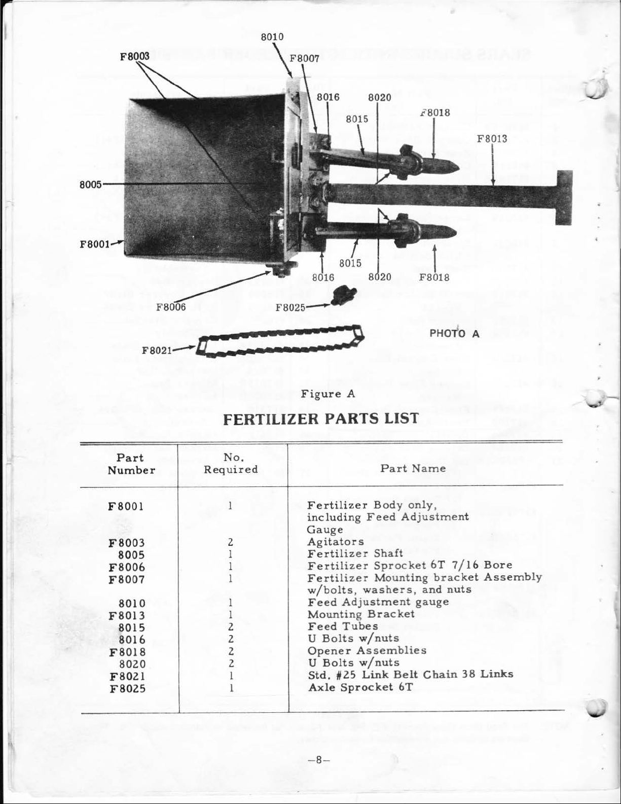
Part
Number
F8001
F8003
8005
F8006
F8007
8010
F8013
8015
8016
F8018
8020
F8021
F8025
FERTILIZER
No.
Required
1
2
1
1
1
1
1
2
2
2
2
1
1
Figure
Fertilizer
including
Gauge
Agitators
Fertilizer
Fertilizer
Fertilizer
w/bolts,
Feed
Mounting Bracket
Feed
U
Opener
U
Std.
Axle Spro
A
PARTS
Feed
washer
Adjustment
Tubes
Bolts
Bo
lts
#25
w/nuts
Assembli
w/nuts
Link
LIST
Part
Body
Shaft
Sprocket
Mounting
cket
PHO"fO A
Name
only,
Adjustment
6T
bracket
s,
and
gauge
es
Belt
Chain
6T
7/16
nuts
38
.........
Bore
Assembly
Links
-8-
Page 9
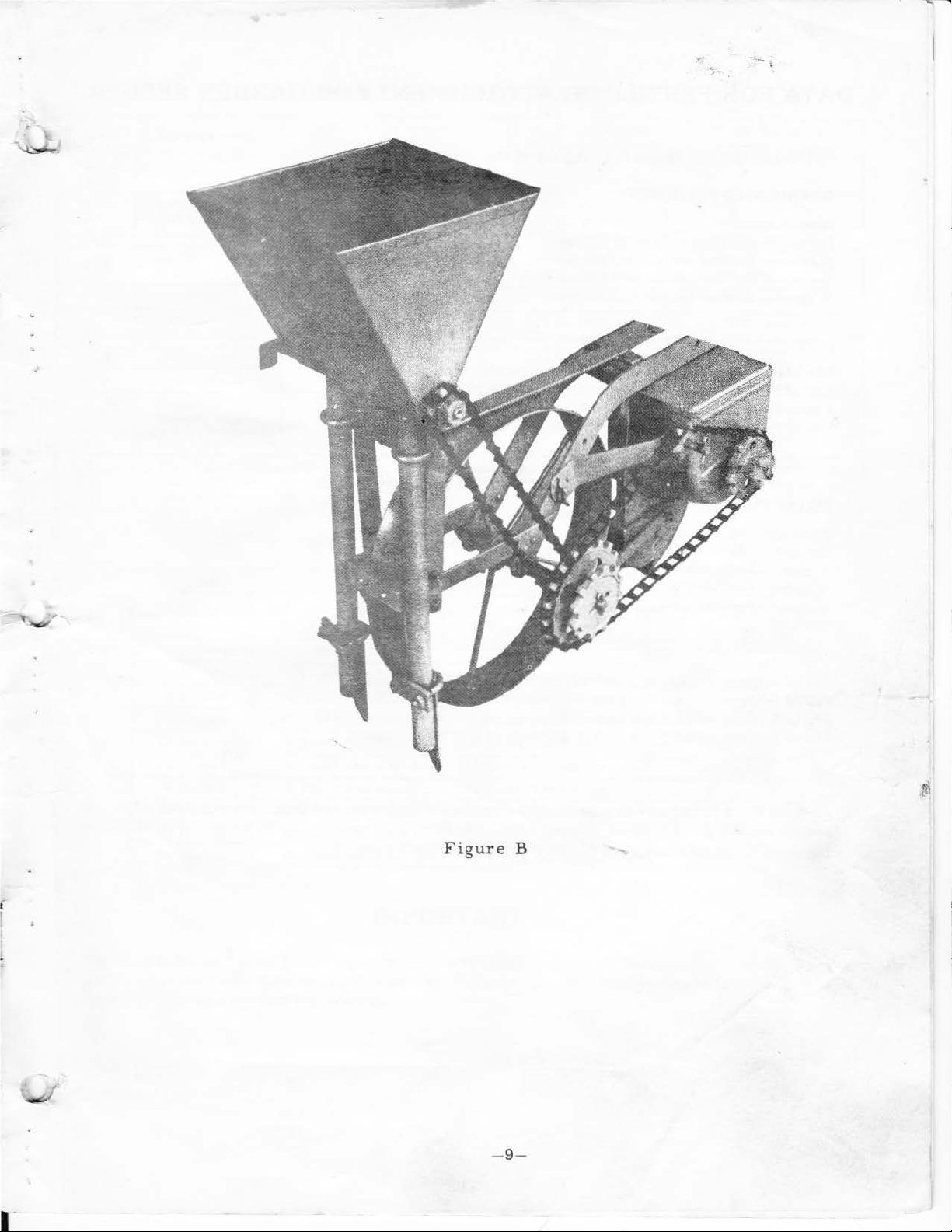
r
Figure
B
- 9-
Page 10
•
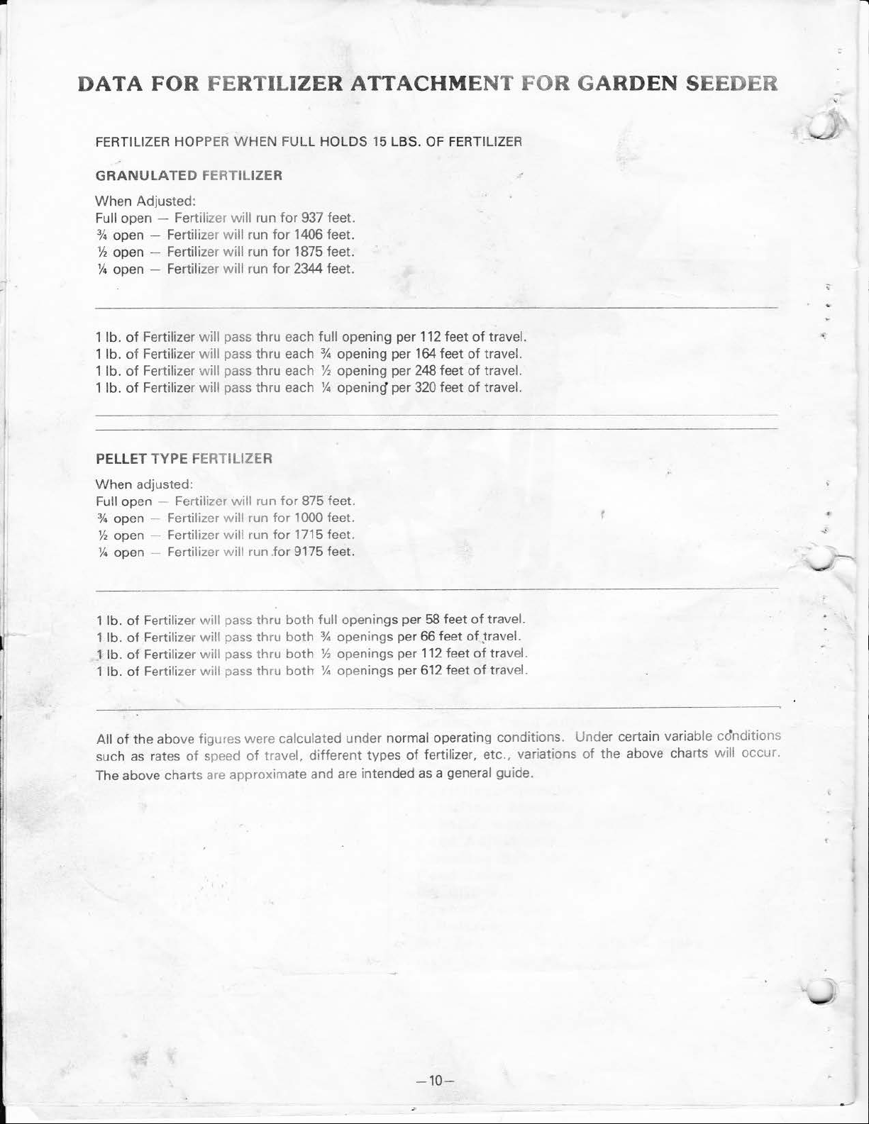
DATA
FERTILIZER HO
FOR FERTILIZER ATTACHME NT
PPER
WHEN FULL
GRANULATED FERTILIZE R
When
Adjusted:
Full open - Fertilizer
% open - Fertilizer
Y2
open - Fertilizer
!14
open - Fertilizer
1
lb.
of
Fertiliz
er
1
lb.
of
Fertilizer
1
lb.
of
Fertilizer
lb.
of
1
Fertilizer
PELLET TYPE
When
adjusted:
Full open - Fertilizer
% open - Fertilizer
Y2
open - Fertilizer will run
will
will
will
will
will
pass
will
pass
will
pass thru each
will
pass
FER
TILIZER
will
will
run
for
937 feet.
run
for
1406 feet.
run
for
1875 feet.
run
for
2344 feet.
thru
each full opening per
thru
each % openi
thru
each % opening per 320 feet
run
for
875 feet.
run
for
1000 feet.
for
1715 feet.
% open - Fertilizer will run .for 9175 feet.
HOLDS
Y2
15
LBS.
ng
per
164
opening per 248 feet
OF
FERTILIZER
112
feet
feet
of
of
of
of
FOR GARDEN
travel.
travel.
travel.
travel.
SEEDER
1
lb.
of
Fertilizer
1 lb.
of Fertilizer
l lb.
of
Fertilizer will pass thru
1 lb.
of
Fertilizer
of
the
All
such as rates
The above charts
above figures were calculated under normal operating conditions. Under certain variable cdnditions
of
will
pass thru
will
pass thru
will
pass thru
speed
are
approximate and are intended
both
full openings per
both
% openings per
both
Y2
openings per
both
% openings per 612 feet
of
travel, different types
58
feet
of
travel.
66
feet
of
,travel.
112
feet
of
travel.
of travel.
of
ferti lizer, etc., variations
as
a general guide.
of
the
above charts will occur.
-1
0-
Page 11

l
Pocket
Sprocket
Disc
A
A12
B12
c
12
D12
Ell
F
12
G
12
E2
F2
G2
J2
-
.:..rrangemen
Seed
Lettuce
Carrots
Onions
Spinach
Radish
Parsnip
Beets
Swiss
Pea
Sweet
Peas
Kidney
For
For
inch
time
Chard
Beans
Corn
Beans
Muskmelon
Field
es
are
is
desired
DRILL
and
to
be
18
I 2 T'
Cucumber
These
planted.
t
Corn, Sweet
desired.
SOWING
Tooth
400
400
300ft.
230
120ft. per
185
185ft. per
400ft. per lb.
400
415ft.
200ft. per lb.
ooth
165
Corn,
On
On
ft.
ft.
ft.
ft.
ft.
ft.
Seed
Wheel
Hopp
per
oz.
per
oz.
per oz.
per oz.
per
oz.
oz.
per
oz.
oz.
per
lb.
per
lb.
Peas,
Discs
er
Kidney
also
CHART
12
Tooth
12
Tooth
600 ft.
600ft.
450ft.
350f
t.
250
ft.
350ft. per oz.
2 7 5 ft.
275
ft.
600
ft.
600
ft.
625
ft.
300ft. per lb.
Beans,
can
be
when
used
On
Whe
On
Hopper
per oz.
per
oz.
per oz.
per
oz.
per
oz.
per
oz.
per
per lb.
per lb.
per
spacings
where
oz.
lb.
e l
more
12
Tooth
18
Tooth
900
ft.
900
ft.
600ft. per oz.
470ft.
335
ft.
470ft. per oz.
370ft. per oz.
370ft. per oz.
900ft. per
900
ft.
835
ft.
400 ft.
from
16
inches
than one
On
Wheel
On
Hopper
per oz.
per
per
oz.
per oz.
per lb.
per
per
seed
oz_
lb.
lb.
lb.
to
at
72
a
I
Spacing
1
inch
2
inches
3
inches
4
inches
6
inches
8
inches
12
inches
16
inches
24
inches
36
inches
48
inches
72
inches
l
HILL
18
Tooth on
12
Tooth
18
Tooth
12
Tooth
1.
t
~'
ooth
6
Tooth
6
Tooth
18
Tooth
12
Tooth
12
Tooth
6
Tooth
6
Tooth
SO
Sprocket
Wheel
On
Wheel
On
Wheel
On
Wheel
On
Wheelll-
On
Wheel
On
Wheel
On
Wheel
On
Wheel
On
Wheel
On
Wheel
On
Wheel
WING
IMPORTANT
The Sears Suburban Tractor Seeder is guaranteed
used in accordance
these instructions are
with
the preceding instructions.
not
read and followed.
CHART
Arrangement
6
Tooth
6
Tooth
12
Tooth
12
Tooth
18
Tooth
12
Tooth
1 8
Tooth
12
Tooth
12
Tooth
18
Tooth
12
Tooth
18
Tooth
for
reasonable accuracy, dependability .and economy
We
cannot guarantee best results and full satisfaction
On
On
On
On
On
On
On
On
On
On
On
On
Hopper
Hopper
Hopper
Hopper
Hopper
Hopper
Hopper
Hopper
Hopper
Hopper
Hopper
Hopper
Pocket
Disc
12
12
12
12
12
12
12
2
2
2
2
2
when
if
\\
Page 12
[Sears
1·
owners
The Model
s
ide
of
the
when
requesting
Fertilizer.
All
parts
ROEBUCK
When
on
you
ordering
request
will
be billed
Number
frame.
listed
AND
parts
or
parts
will
be
found
Always mention
service
herein
acco
CO ..
by
will
mail,
rdin
or
may
or
be
shipped
gly.
repair
on a
plate
atta
the
Model
parts
for
your Seeder
be
ordered
SIMPSONS-SEARS
selling
at
through
prices
prevailing
will
ched
Number
SEARS,
LIMITED.
be
furnished
prices
to
the
and
and
\
....
-
manual
MODEL
597.261620
How
Repair
to
NO
.
Order
Parts
WHEN
ING
1.
2.
ORDERING
INFORMATION
The
PART
The
PART
PARTS. ALWAYS
AS
SHOWN
NUMBER
DESCRIPTION
GIVE
THE
IN
THIS
LIST.
3.
The
MODEL
597.261620
4.
The
NAME
Seeder
When you b
from
something
can
offer ...
Across
country, wherever
move
Service
ing
trustworthy
serv1ce
See>rs
and
uy
Sears you
that
Sears
town
in
the U.S.A.,
follow
technicians
specified
FOLLOW-
NUMBER
OF
ITEM-
Fertilizer
mercha
get
an
nobody
Service.
or
acro
ss the
you
live
Sear
s yo
u,
provid
,
CC'".•p.JtP
using
fact~ry
parts.
ndis
extra
else
o•·' •
~,
only
e
~
~
-
~
.......
' '
l
'
•
,
SEARS
IS
AT
WHEREVER
IN
YOUR
OR
MOVE
THE
SERVICE
SERVICE
YOU
U.S.A
LIVE
.
-----------------------------------------------------------------
Sears,
and
Roebuck
Simpsons
and
Sears
Co.,
Chicago,
Ill.
Limited, Toronto
60684
U .S .A.·
PRINTED
IN
.;
--
U S A.
 Loading...