


David TI-2000
Table of contents
 Loading...
R
EDITION/REVISION A/0
NINGBO DAVID
SERVICE MANUAL
TI-2000
TRANSPORT INCUBATOR

NINGBO DAVID MEDICAL DEVICE CO., LTD.
ADD: NO.158 DAQING ROAD SHIPU TOWN XIANGSHAN COUNTY ZHEJIANG PROVINCE P.R.CHINA
POST CODE: 315731 FAX: 0086-574-65962111
MARKETING CENTER: NO. 100, JINGHUA ROAD, HI-TECH INDUSTRIAL DEVELOPMENT ZONE,
NINGBO, CHINA
POST CODE: 315000
TEL: 0086-574-87800008, 87800009 FAX: 0086-574-87801111
E-MAIL: sales@chinadavid.cn david@mail.nbptt.zj.cn
WEBSITE: http://www.nbdavid.com
EUROPEAN REPRESENTATIVE: SHANGHAI INTERNA
ADD: EIFFESTRASSE 80, 20537 HAMBURG, GERMANY
TEL: 0049-40-2513175 FAX: 0049-40-255726
TIONAL HOLDING CORP. GMBH (EUROPE)
EDITION/REVISION A/0

SERVICE MANUAL FOR INCUBATOR EDITION/REVISION A/0
WARRANTY
The product described in this manual is warranted against defects in materials or workmanship for one year
from the dates of shipment except the following items:
1. All consumable and disposable products are guaranteed to be free for repairing because of defects
upon shipment only.
2. Normal drop-in services are not included in the 1-year warranty.
3.Damage caused by improper carrying; for example, drop the device on the ground during transporting or
moving.
4. Damage caused by fire, earthquake, flood and other natural calamity.
During the warranty period any defective parts other than those listed above will be replaced at no charge
to the customer. This warranty is rendered void and our company cannot be held liable for conditions resultant
there from if:
1.Damage to the unit is incurred as a result of mishandling.
2.The customer fails to maintain the unit in a proper manner.
3.The customer uses any spare parts, accessories, or fittings not specified or sold by our company when
this product is changed, maintained or repaired.
4.Damage caused by ignoring the attention or instruction of the manual.
5.Damage caused by ignorance of the instructions in this manual.
6.Damage caused by the environment of operation, including the electric condition or installation
conditions, which do not accord with the instruction of the manual.
7.Damage caused by unauthorized dealer.
8.Damage caused by reducing the system safety due to stalling the accessories, which do not accord with
the safety requirements of this product.
9.Enlarge the application scope of this product at will.
The company is not responsible for the invalid warranty caused by the damages accidentally including the
wastage, the belongings damages or individual injury.
Prior to initial use, the capability and mechanized integrity of the product should be tested, afterward, at
least once every one year; at the same time, a record is a must. To comply with this standard, we recommend
that you participate in our preventive maintenance program during the warranty period. This service can be
performed by certified technicians and authorized dealers that have passed through our product service
department.
I6
i

SERVICE MANUAL FOR INCUBATOR EDITION/REVISION A/0
SERVICE COMMITMENT
For optimal performance, product service should be performed only by qualified service personnel.
Technical Services representatives can be reached for fixations and are dispatched for required maintenance by
calling 0086-574-87800002, 87801003. Customers outside China should contact their local factory-authorized
distributor for service.
The device, accessories and the packaging have to be disposed of waste correctly at the end of the
usage. Please follow Local Ordinances or Regulations for disposal.
COMPLEMENTARY NOTICE
Since our factory, conducts a continuous product improvement program, circuit and component
improvements are sometimes incorporated into equipment before they can be incorporated into the printed
manuals. Therefore, some parts used in your equipment may be different than those which appear in the parts
list of this manual. This sometimes occurs due to difficulty in parts procurement, but does not alter the function
of the equipment When this occurs, changed material is provided on separate sheets of the manual. If it brings
about trouble in reading this manual, we beg your pardon.
This manual contains all of the repairs information. Repairs and authorized modifications should be
performed only by qualified service personnel to maintain your warranty and to avoid creating safety hazards.
We cannot assume responsibility for any conditions affecting the proper operation of this equipment which may
result from unauthorized repair or modification.
TABLE OF DEFINITIONS AND SYMBOLS
TECHNICAL DEFINITIONS
INCUBATOR TEMPERATURE. Air temperature at a point 10cm above and centered over the mattress surface.
INCUBATOR TEMPERATURE. Air temperature at a point 10cm above and centered over the mattress surface.
INCUBATOR TEMPERATURE EQUILIBRIUM. The condition reached when the average incubator temperature
does not vary more than 1.0℃ over a period of one hour.
TEMPERATURE UNIFORMITY. The amount by which the average temperature at each of four points 10cm
above the mattress surface differs from the average incubator temperature at temperature equilibrium.
TEMPERATURE VARIABILITY. The variability of the incubator temperature that will be observed over a
one-hour period after incubator temperature equilibrium has been reached.
TEMPERATURE RISING TIME. The time required for the incubator temperature to rise 11℃, when the air
control temperature is at least 12℃ above ambient.
TEMPERATURE ALARM CHECKOUT STATE. The difference point between the real temperature and control
temperature is within ±0.2℃ and such status lasts for over 3 minute.(When check out the temperature alarm
function, operation should be enter this state.)
ii
I6
SERVICE MANUAL FOR INCUBATOR EDITION/REVISION A/0
NOTE, IMPORTANT, CAUTION AND WARNING
NOTE: A note is inserted in text to point out procedures or conditions that may otherwise be misinterpreted or
overlooked. A note may also be used to clarify apparently contradictory or confusing situations.
IMPORTANT: Similar to a Note but used where greater emphasis is required.
CAUTION: A Caution is insert in a text to call attention to a procedure that if not followed exactly, can lead to
damage or destruction of the equipment or improper operation.
WARNING: A Warning is insert in a text to call attention to dangerous or hazardous conditions inherent to the
operation, cleaning, and maintenance of the equipment that may result in personal injury or death of the
operator or patient.
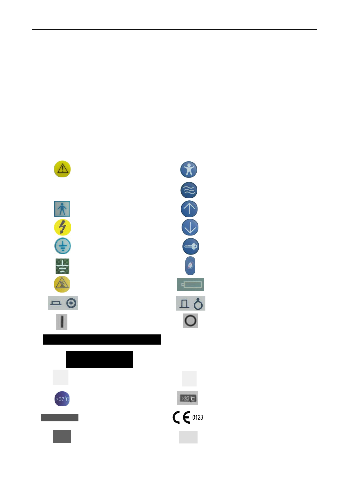
SYMBOLS
Attention!
Consult Accompanying Documents. Skin Mode Key
Class I Equipment
Air Mode Key
Type BF Applied Part
Caution: Electric Shock Hazard
Protective Earth (Ground)
Earth (Ground)
Caution, Hot Surface
Controller Switch On
Power Switch On
Temperature Set Point Up Key
Temperature Set Point Down Key
Set Key
Silence/Reset Key
Battery Active Indicator
Controller Switch Off
Power Switch Off
DC12V 10A/24V 6A Power Supply
AC 220-230V ,50Hz Power Supply
Lighting Switch On
>37 function key℃
3.15AL/250V F Type Fuse
Date Of Manufacture Serial Number
I6
Lighting Switch Off
>37℃ indicator
CE MARKING
iii

SERVICE MANUAL FOR INCUBATOR EDITION/REVISION A/0
SEASONAL SAFETY CHECK
1. Please clean the plug of power cord at least once a year. Too much dust on plug may cause the fire.
2. The following safety checks should be performed at least every 12 months by a qualified person who has
adequate training, knowledge, and practical experience to perform these tests. The data should be recorded in
an equipment log. If the device is not functioning properly or fails any of the above tests, the device has to be
repaired.
1
○
. Inspect the equipment and accessories for mechanical and functional damage.
2.
○
Inspect the safety relevant labels for legibility.
3
○
. Inspect the fuse to verify compliance with rated current and breaking characteristics.
4
○
. Verify that the device functions properly as described in the instructions for use.
5
○
. Test the protection earth resistance according IEC 60601-1:1988 + A1:1991 + A2:1995: Limit 0.1Ω.
6
○
. Test the earth leakage current according IEC 60601-1:1988 + A1:1991 + A2:1995: Limit: NC 500μA,
SFC: 1000μA.
7
○
. Test the enclosure leakage current according to IEC 60601-1:1988 + A1:1991 + A2:1995: Limit: NC
100μA, SFC: 500μA.
8
○
. Test the patient leakage current according IEC 60601-1:1988 + A1:1991 + A2:1995: Limit: for a.c.:
100μA (BF), for d.c.: 10μA (BF).
9
○
. Test the patient leakage current under single fault condition with mains voltage on the applied part
according IEC 60601-1:1988 + A1:1991 + A2:1995: Limit: for a.c.:500μA (BF), for d.c.: 50μA (BF).
10
○
. According to the test methods of IEC 60601-1:1988 + A1:1991 + A2:1995, the patient leakage current
(net voltage should be added on the applied part) of the testing device must less than 5000μA.
11
○
. Test the patient auxiliary leakage current according IEC 60601-1:1988 + A1:1991+ A2:1995: Limit: NC
for a.c.: 100μA (BF), for d.c.: 10μA (BF).SFC 500μA (BF), for d.c.: 50μA (BF).
iv
I6

SERVICE MANUAL FOR INCUBATOR EDITION/REVISION A/0
TABLE OF CONTENTS
SECTION PAGE
1. GENERAL INFORMATION…………………………………………………………………………1-1
1.1 INTRODUCTION…………………………………………………………………………………1-1
1.2 ACCESSORIES……………………………………………………………………………………1-1
2. INSTALLATION…………………………………………………………………………………2-1
2.1 UNPACKING………………………………………………………………………………………2-1
2.2 ASSEMBLING THE HOOD ON THE CABINET………………………………………………………2-1
2.3 CONNECTION TO EXTERNAL POWER SOURCES………………………………………………2-4
2.4 INSTALLATION OF OXYGEN CYLINDERS………………………………………………………2-5
2.5 CONNECTION OF REGULATOR………………………………………………………………2-5
2.6 OPERATION CHECKOUT PROCEDURE……………………………………………………………2-6
3.TECHNICAL INFORMATION…………………………………………………………………………3-1
3.1SPECIFICATION……………………………………………………………………………………3-1
3.2 WORKING PRICIPLE …………………………………………………………………………3-6
3.2.1 GENERAL……………………………………………………………………………………3-6
3.2.2 TEMPERATURE CONTROL……………………………………………………………………3-9
3.2.3 ALARMS…………………………………………………………………………………………3-9
3.2.4 SILENT HAND PORTS, IRIS PORTS AND IV SOFT PORT………………………………………3-12
4. PREVENTIVE MAINTENANCE…………………………………………………………………4-1
4.1 GENERAL………………………………………………………………………………………4-1
4.2 CLEANING………………………………………………………………………………………4-1
4.2.1 DISASSEMBLY FOR CLEANING………………………………………………………………4-1
4.2.2 CLEANING AFTER DISASSEMBLY………………………………………………………………4-3
4.2.3 REASSEMBLY AFTER CLEANING……………………………………………………………4-4
4.3 GAS STERILIZATION……………………………………………………………………………4-6
I6
v

SERVICE MANUAL FOR INCUBATOR EDITION/REVISION A/0
5. MAINTENANCE……………………………………………………………………………………5-1
5.1 INTRODUCTION…………………………………………………………………………………5-1
5.2 REPLACEMENT OF INNER BATTERY AND FUSE…………………………………………………5-1
5.3 REPLACEMENT OUTER FUSE…………………………………………………………………5-2
5.4 MAINTENANCE AND REPALCEMENT AND THE STORAGE BATTERY……………………………5-2
5.5 SYSTEM SET PROCEDURE………………………………………………………………………5-4
5.5.1 INTRODUCTION…………………………………………………………………………………5-4
5.5.2 BRIEF INTRODUCTION…………………………………………………………………………5-4
5.5.3 PROCEDURE……………………………………………………………………………………5-5
5.6 PROCEDURE OF TROUBLRE-SHOOTING…………………………………………………………5-7
5.6.1 INTRODUCTION…………………………………………………………………………………5-7
5.6.2 TEST DEVICE……………………………………………………………………………………5-7
5.6.3 TEMPERATURE SIMULATION DEVICE…………………………………………………………5-8
5.6.4 ALARM CODE……………………………………………………………………………………5-9
5.6.5 CHECK FLOW CHART…………………………………………………………………………5-11
6. REPLACEMENT SPARE PARTS……………………………………………………………………6-1
6.1 PREFACE…………………………………………………………………………………………6-1
7. DIAGRAMS…………………………………………………………………………………………7-1
7.1 GENERAL…………………………………………………………………………………………7-1
vi
I6

SERVICE MANUAL FOR INCUBATOR EDITION/REVISION A/0
SECTION 1
GENERAL INFORMATION
1.1 INTRODUCTION
This manual provides instructions for installation, maintenance and repair the David transport
Incubators, Model TI-2000.
This manual is intended for use only by trained, qualified service personnel. Instructions for the
operator of the equipment are provided in a separate operator’s manual.
1.2 ACCESSORIES
Accessories available of use with the Incubators are illustrated in Figure 1.1. Refer to Section 6 of
this manual for part numbers.
I.V. POLE
PAWL LATCH ACCESS DOOR ACCESS DOOR LATCH
I.V. SOFT PORT HOOD
TEMPERATURE CONTROLLER
HOOD RETAINER
OXYGEN CYLINDER
CART
LOCK MECHANISM
HEIGHT ADJUSTMENT LATCH
CASTER
FIGUER 1.1 DESCRIPTION OF PARTS
I6
1-1

SERVICE MANUAL FOR INCUBATOR EDITION/REVISION A/0
SECTION 2
INSTALLATION
2.1 UNPACKING
Typically, the stand and the hood are shipped in separate cartons. When removing the equipment from
the cartons, take care not to scratch or damage unprotected surfaces. Remove all packing materials from the
shell assembly and check all the spare parts according to the packing list.
2.2 ASSEMBLING THE HOOD ON THE STAND
WARNING: For safety, the Transport Incubator should always be handled by two persons.
A. See figure 2.1, install the caster and connect the unit stand and the unit box.
1. Install the spring washer on the wheel, and then connect the stand, fasten it with spanner and from the
connection of support pole and stand.
Support Pole
Connect the wheel Connect the support pole
NOTE: Two Long Support Poles must be installed closing with the side of the Height Adjustment
Locking Handle when installing the Support Poles.
2. Place the unit box on the unit stand correctly, pull out the fixed lock as the arrow 1 indicates, and make it
break away the unit stand as the arrow 2 indicates.
Main Body
Adjustable Stand
Fixing Lock
CORRECT POSITION INSTALL MAIN LOCK THE MAIN BODY AND ADJUSTABLE STAND
BODY ONTO THE ADJUSTABLE STAND
I6
2-1
SERVICE MANUAL FOR INCUBATOR EDITION/REVISION A/0
LOCKED STATUS UNLOCKED STATUS
FIGURE 2.1 ASSEMBLING THE MAIN BODY ONTO THE ADJUSTABLE STAND
B. Refer to figure2.2, Pull out the Height Adjustment Latch follow arrow 1, and the same time raise the
Adjustable Stand toward the arrow 2, lock the Wheel of the Stand when the Unit rise the top place.
Height Adjustment Latch
Please read section 2.2 carefully when operating the unit stand.
1、 When placing the unit body on the stand, you must ensure that it is in the
state of the fixing and locking condition (see figure 2.1) to avoid the unit
body falling from the stand when moving.
2、Unit stand: three steps adjusstable, when adjust its height, see figure 2.2,
first, pull the control pole, loosen it after giving the strength for lifting or
lowering the unit stand, and then you can adjust its height. When adjust
then in the right position, ir will sound “ka”, or else, the unit stand can not
be adjusted to the right position.
2-2
I6

SERVICE MANUAL FOR INCUBATOR EDITION/REVISION A/0
WHEEL UNLOCKED WHEEL LOCKED
NOTE: The Wheels faced down as to be locked indicated by arrow 3. The Wheels faced down as to be
unlocked indicated by arrow 4.
FIGURE 2.2 RAISE THE STAND AND LOCK THE WHEEL
WARNING: To prevent injury, keep fingers clear of Wheels and other moving parts.
WARNING: To prevent the Incubator from sliding when parked on an incline, the Stand
front locking casters must be facing down the incline and locked.
C. See figure 2.3, Insert the I.V Pole into the base of I.V Pole in the way of arrow 1, and then tighten it in the
way of arrow 2.
I.V. Pole
1
I.V. Pole Base
FIGURE 2.3 INSTALL THE I.V. POLE
WARNING: The Incubator must be attached to the Stand using the lock mechanism provided.
Failure to do so could result in the Incubator separating from the Stand if
sufficiently tilted, particularly with the Incubator transport.
2.3 CONNECTION TO EXTERNAL POWER SOURCES
A. The AC Power Cord Receptacle can be connected to standard 3-wire hospital outlet.(See figure 4.1)
B. The External DC Power Cord Receptacle should be connected with The External DC Power Cord provided,
and their voltage should be according with requirement in Table 1.1. (See figure 4.1)
I6
2-3

SERVICE MANUAL FOR INCUBATOR EDITION/REVISION A/0
CAUTION: Make sure correct continuity of ground between chassis of battery and AC PLUG
groundingpin before use.
To ensure grounding reliability, connect AC power cable only to a properly grounded 3-wire
hospital-grade or hospital-use outlet of the proper voltage and frequency. DO NOT USE EXTENSION
CORDS.
2.4 INSTALLATION OF OXYGEN CYLINDER
WARNING: The oxygen cylinders can become hazardous projectiles if the gas is released
rapidly due to damage or other causes. Cylinders must be securely fastened to
prevent movement or damage.
A. Before attempting to install the Oxygen Cylinders, ensure that the Draw Clamp Keeper for the retaining
clamp is in the proper position for the size of oxygen cylinders being mounted on the incubator.
B. Slide the oxygen cylinder into the compartment provided after lock button connection press lock wrench
toward arrow direction to fix oxygen bottle. Tighten the yokes on the cylinders; make sure the cylinders are
firmly clamped (See Firgure2.4).
LOCK HAND
CYLINDER
DRAW HOOK
Cylinder must be tightening to prevent it movement.
FIGURE 2.4 TIGHTEN CYLINDER
2.5 CONNECTION OF REGULATOR
Refer to the figure 2.5; connect regulator with oxygen cylinder in the proper position. After connection, the
oxygen pressure gauge must be placed in level.
FIGURE 2.5 CONNECT OXYGEN FEEDING VALVE
2-4
I6

SERVICE MANUAL FOR INCUBATOR EDITION/REVISION A/0
2.6 OPERATIONAL CHECKOUT PROCEDURE
The Operational Checkout should be performed before the Incubator is first placed into service and after
any disassembly for cleaning or maintenance.
WARNING
1. Infant must be taking out from the incubator before general operation and functional
checkout procedure.
2. Incubator must be stopped to use if it cannot pass the following operation checkout
procedure or find any foreseeable trouble. The troubleshooting must be serviced by
qualified person.
3. The checkout procedure related to temperature enable to use, only when set
temperature must be high 3 than ambient temperature.℃
A Check to tighten the wheels
CAUTION: Before mount the main body of the incubator on the stand, checkout wheels must be
operated as follow. User to avoid the risk of the wheel should check the wheel regular.
Elevate each end of incubator approximately 2cm and test on each wheel one by one. A loosened wheel can
result in incubator instability or tip-over while Incubator is transported. Do not use Incubator before the
loosened wheel is replaced.
IMPORTANT: Two people are required to implement the test. One elevates Incubator and the other
check the wheel. The minimum weight of Incubator to be elevated is approximately 100
kilograms.
B Check different parts of Hood and stand: Follow the procedures illustrated by figures.
Perform this Operational Checkout Procedure along with the Operational Checkout Procedure provided
for the Controller before first placing the Incubator into service and after any disassembly or maintenance.
CHECK STAND
I6
2-5

SERVICE MANUAL FOR INCUBATOR EDITION/REVISION A/0
Pull out the Height Adjustment Latch follow arrow 1 and at the same time press the stand, the stand should
fall down slowly until the minimum height, release the Height Adjustment Latch, it should be locked
automatically. The stand should have two-step adjustable height and can lock automatically.
NOTE: The stand of incubator should be dropped down to the lowest height when the Incubator
pushed into ambulance.
CHECK FRONT ACCESS PANEL
2
1
ACCESS PANEL LATCHE LOCKED ACCESS PANEL LATCHEUNLOCKED
Pull and rotate access panel latches to unlocked position as same as the arrow 1 and arrow 2, open the
access panel to the full open position (hanging straight down). Close the access panel and rotate both latches
until they are fully engaged. Both latches must be fully engaged to prevent accidental opening of the access
panel.
CHECK THE ACCESS DOOR LATCHES AND GASKETS
Press the door release of each access door. The access door should spring open. Check that the access
door gaskets are airproof.
2-6
I6

SERVICE MANUAL FOR INCUBATOR EDITION/REVISION A/0
CHECK THE IRIS ENTRY PORTS
Rotate the outer ring of the Iris Port; the iris should open and close as rotation is continued through 360
degrees.
CHECK THE SHELL LATCHES AND HOOD RETAINERS
UNLOCKED LOOSEN
LOCKED
Check the shell latches and hood retainers. All four latches and retainers should be properly secured.
I6
2-7

SERVICE MANUAL FOR INCUBATOR EDITION/REVISION A/0
CHECK MATTRESS TRAY
STOPPER
Open the Head End Access Panel and slide the tray out to the Incubator until it reaches its fully extended
position indicated by the arrow. Check that the tray is stable when force is applied to extended portion. The
mattress tray should be draw out while pressing the stopper beside the mattress tray as show as the arrow.
Return the mattress tray and close the panels. Both latches must be fully engaged to prevent accidental
opening of the access panel.
CHECK THE AIR INTAKE MICROFILTER
WARNING: A dirty Air Intake Microfilter may affect oxygen concentration and /or cause
Carbon Dioxide build-up. Be sure the filter is checked on a routine basis
commensurate with local conditions. It must be changed at least every two
months or visibly dirty.
AIR FILTERING MATERIAL
Loosen two thumbscrews on the air filter cover and then remove the cover. Remove the filter and inspect
2-8
I6

SERVICE MANUAL FOR INCUBATOR EDITION/REVISION A/0
it; if the microfilter is visibly dirty, replace it.
CHECK THE OXYGEN SYSTEM
Connect the oxygen input valve, Introduce 8L/min oxygen, then monitor level within hood with a calibrated
oxygen analyzer to verify that they reach the predicted level as indicated on the Oxygen Concentration Guide
located on Incubator.
CHECK THE BOLT OF STORAGE BATTERY TRAY
After loosen the switch bolt of storage battery tray, the storage battery tray should be pulled out. After
pushing back storage battery tray, tighten the switch bolt; the storage battery tray should not be pulled out.
C. Check power supply mode and check the power failure alarm
Disconnect AC power supply cord under the temperature controller turned on, the unit should be changed
power supply to DC power; Disconnect DC power supply cord, the unit should be changed power supply to
storage battery. Turn off the controller, loosen the bolt of storage battery tray and slide the Battery tray out
approximately 5cm to disconnect the internal batteries; then turn on temperature controller again, the power fail
indicator on the controller should light and a steady audible alarm should sound. The alarm should terminate
automatically when the storage battery is restored.
D . Check Temperature Controller
WARNING: The Incubator should not be used if it fails to function as described. Service
should be referred to qualified personnel.
NOTE: Please operate the Controller according to the Manual strictly. Do not to press the key freely.
Perform this Operational Checkout Procedure along with the Operational Checkout Procedure provided for
the Hood before first placing the incubator into service and after any disassembly or maintenance.
CHECK DEVIATION ALARM (AIR MODE)
Close all of the doors, windows and set the temperature to 32 ºC. Enter Temperature Alarm Checkout Status
(refer to TABLE OF DEFINITIONS AND SYMBOLS). Warm up the displayed air temperature(fan warm air
within the Hood) to check High Temperature Deviation Alarm (+3℃ deviation alarm). Set the temperature to
35℃, Enter Temperature Alarm Checkout Status. Open the Access Panel to check Low Temperature Deviation
Alarm. (-3℃deviation alarm). When High Temperature Deviation or Low Temperature Deviation
I6
2-9

SERVICE MANUAL FOR INCUBATOR EDITION/REVISION A/0
occurs, the Alarm Indicators should activate, Temperature Deviation Alarm Message E09 or E10 should appear
on Set Temperature Display and the audible alarm should sound.
NOTE: This alarm will not occur until the temperature fails more than 3℃ up or below set point. When
checking the Low Temperature Deviation Alarm, the ambient temperature must be lower than
set point or fan the air within the Hood, then the alarm will occurs.
CHECK THE DEVIATION ALARM (SKIN MODE)
Insert the Skin Temperature Sensor into Skin Socket.
The arrow of Skin temperature sensor should aim
at the gap for right insert.
1. Must handle the Sensor Plug to insert or pull out the sensor, don’t pull the Sensor by
the cord.
2. Never place the Skin Temperature Sensor under the Infant or use it rectally.
3. Don’t bend at the joint of the sensor.
Set the Skin Set Temperature to 35℃, to Enter Temperature Alarm Checkout Status. Place the Skin
Temperature Probe into trough with the temperature of over approximately 37℃ or below 33℃respectively,
check the Deviation Alarm of ±1℃. When the Temperature High or Low Deviation Alarm occurs, the Alarm
Indicators should activate, the Temperature Deviation Alarm Message E09 or E10 should appear on the Set
Temperature Display and the audible alarm should sound.
NOTE: The Low Deviation Alarm will not occur until the temperature falls down 1.0℃ than set point.
CHECK SKIN TEMPERATURE SENSOR ALARM
Select Skin Mode Control, Disconnect the Skin Sensor from the receptacle. The audible and visual alarms
should activate. Set Temperature Display indicates E04. When the Skin Sensor reconnected, the Incubator
should return to normal operation.
Select Skin Mode Control, keep Skin Temperature Sensor 2ºC lower than this Set Point. The audible and
visual alarms should activate when the Incubator enters temperature alarm checkout state (refer to
2-10
I6

SERVICE MANUAL FOR INCUBATOR EDITION/REVISION A/0
descriptions of terms and symbols concerned). Set Temperature Display indicates E08.
CHECK OVER TEMPERATURE ALARM
Select Air Mode of operation, in turn press UP, Down and Silence/Reset Key simultaneous, the Set Display
should go blank, Heating indicators lights illuminate after Temperature Controller is put into Over Temperature
Test Mode. After a while, the Over Temperature Alarm Indicator shall be activated with audible and visual. Set
Temperature Display shows E05. Press the Silence/Reset Key, alarm is over and the Controller return to set
status.
Select Skin Mode of operation, in turn press UP, Down and Silence/Reset Key simultaneous, the Set Display
should go blank, Heating indicators lights illuminate after Temperature Controller is put into Over Temperature
Test Mode. After a while, the Over Temperature Alarm Indicator shall be activated with audible and visual. Set
Temperature Display shows E05. Press the Silence/Reset Key, alarm is over and the Controller return to set
status.
CHECK FAN MOTOR FAILED ALARM
Refer to figure 5.2; raise up the Hood and take out the Mattress Tray. Hold the fan carefully and turn on
the power switch of the Temperature Controller, an alarm should be occur, the fan alarm indicator flashing, Set
Temperature Display will indicate E07, loosen the fan, the fan alarm will be canceled automatically after the fan
turned. The fan should return to normal operation after pressing the Silence/Reset Key.
Air Temperature & Isolate Temperature Probe
Heater
NOTE: To avoid scalding, it must take at least 45 minutes after the incubator stopped working to
perform this operation.
CHECK THE ACCURACY OF TEMPERATURE CONTROL
Select the air mode, and set the air temperature at 36 , after the air temperature enters into the stable ℃
state, put the calibrated temperature measuring device on the position above 10cm from the center of mattress
to measure the air temperature, compared with the indicated air temperature to check whether the deviation
between them is within 1.0℃.
I6
2-11

SERVICE MANUAL FOR INCUBATOR EDITION/REVISION A/0
CHECK DISPLAYING PRECISION OF SKIN TEMPERATURE SENSOR
Put the mercury thermograph for the accuracy within ±0.1ºC into the main baby of incubator and assure
the mercury ball which must be loom above center of the mattress. Choose the air mode control, set the
temperature as 36ºC, enter into incubator temperature equilibrium condition, read the value of the mercury
thermograph, compare the value of the mercury thermograph with 1ºC.
CHECK PRECISION OF SKIN TEMPERATURE SENSOR
Put the skin temperature sensor with the mercury thermograph for the accuracy with ±0.1ºC into the water
cup with the temperature as 30ºC±5ºC. Make the probe of the skin temperature sensor and the mercury ball
as closely as possible and stir enough, then read the value of mercury thermograph. Compare the value of the
skin temperature sensor and the mercury thermograph, and the deviation must be within 0.5ºC.
NOTE: Please check again if the accuracy of the skin temperature sensor exceeds the permissibility
deviation. Please let the professional maintenance man service machine if the accuracy the skin
temperature sensor exceeds the permissibility of deviation again.
Operation of temperature controller checkout is complete. Switch all the switches off and remove the power
cord to stop using Incubator if it is not necessary to use.
2-12
I6

SERVICE MANUAL FOR INCUBATOR EDITION/REVISION A/0
SECTION 3
TECHNICAL INFORMATION
3.1 SPECIFICATION
Specifications for the Incubators are provided in Table 3.1. All specifications maybe subject to change
without advance notice. Open Access Doors and Front Panel, which can alter the air flow pattern, may affect
temperature uniformity, temperature variability, the correlation of the Incubator temperature reading to center
mattress temperature and infant skin temperature.
TABLE 3.1 SPECIFICATIONS
AC power……………………………………………………………………AC220V-230V, 50Hz
DC power………………………………………………………………………12V/10A,24V/6A
Power input………………………………………………………………………400VAProtectively
earthed……………………………………………………………………………………<0.1Ω
Chassis leakage current…………………………………………………NC:<0.5mA,SFC:<1mA
Patient leakage current…………………………………………………Normal Condition<0.1mA
Single Fault Condition: <0.5mA
Patient leakage current (Mains Voltage On The Applied Part ) ……………………………Single Fault
Condition:< 5mA
With respect to IEC601-1, this equipment is Class I, Type BF. Internally powered equipment.
INTERNAL BATTERY SPECIFICATIONS
Type………………………………………………………Topin®TP12-26(12V26AH/20HR)Battery
Quantity………………………………………………………………………………………One
Voltage…………………………………………………………………………………12V/26AH
Charge Time (full discharge)………………………………………………………10 Hours
Life Expectancy……………………………………200times complete charge/discharge cycles
Operating Time at temperature equilibrium ………………………………………………90min
(Set Temp 36℃— Ambient 15℃) (1battery)
Battery length……………………………………………………………………………16cm
Battery width………………………………………………………………………………17cm
Battery height……………………………………………………………………………13cm
Battery weight………………………………………………………………………………9Kg
ENVIRONMENTAL TEMPERATURE (Normal)
Operating Range………………………………………………………………+10℃~+30℃
(NOTE: The Incubator set point must be at least 3℃ higher than ambient.)
Operating Range(Limited)………………………………………………………+0℃~+40℃
Storage Range………………………………………………………………………………-40℃~+70℃
3-1
I6

SERVICE MANUAL FOR INCUBATOR EDITION/REVISION A/0
TABLE 3.1 SPECIFICATIONS (Continued)
ENVIRONMENTAL HUMIDITY
Operating Range………………………………………………30%~75%RH Non-Condensing
Storage Range………………………………………………………………≤93% RH Non-Condensing
ATMOSPHERIC PRESSURE
Shipment and storage atmospheric pressure range……………………………500hPa~1060hPa
Operating atmosphere pressure range……………………………………………700hPa~1060hPa
THE AIR FLOW RATE
Ambient air flow rate………………………………………………………………………<1.0m/s
MPERATURE CONTROL RANGE AND CORRELATIVE SPECIFICATION
Air Mode Control……………………………………………………………………25~37℃
37.0 to 38.0℃, Temperature Override Mode
Skin Mode Control……………………………………………………………………34~37℃
37.0 to 37.5℃, Temperature Override Mode
Temperature Rise Time**(22℃ ambient )……………………………………………≤30minut es
Temperature Variability **…………………………………………………………………≤1℃
Temperature Uniformity**(level mattress)…………………………………………………≤1.5℃
Correlation of Indicated Air Temperature to Actual Incubator Temperature **……………≤0.7℃
(After Incubator Temperature Equilibrium** is reached)
Skin Temperature Sensor Accuracy………………………………………………………≤0.3℃
Deviation between the indicated air temperature and the real temperature…………………≤1.0℃
(under the steady temperature condition)
ALARM (SEE SECTION 3.2)
General Power alarm
Air temperature sensor failure…………………………………………………………Alarm code E01
The isolated air sensor failure……………………………………………………Alarm code E0.2
Deviation of air and isolated sensor failure……………………………………………Alarm code E0.3
Skin temperature sensor failure…………………………………………………………Alarm code E0.4
Over-temp failure……………………………………………………………………………Alarm code E0.5
Motor stop ……………………………………………………………………………Alarm code E0.6
Motor retard ……………………………………………………………………………Alarm code E0.7
Wrong position of skin sensor failure……………………………………………………Alarm code E0.8
High deviation alarm………………………………………………………………………Alarm code E0.9
Low deviation alarm…………………………………………………………………………Alarm code E1.0
Low Voltage Alarm………………………………………………………………Alarm code E1.1
Internal system failure………………………………………………………..Alarm code H0.1~H1.3
3-2
I6

SERVICE MANUAL FOR INCUBATOR EDITION/REVISION A/0
TABLE 3.1 SPECIFICATIONS (Continued)
PHYSICAL DIMENSIONS
Height From Top To Floor(Highest Position In Stand)………………………………………128cm
Height From Top To Floor(Lowest Position In Stand)………………………………………100cm
Length………………………………………………………………………………………170cm
Width…………………………………………………………………………………………50cm
Incubator Main body Weight (Including Incubator and one Battery)…………………………65Kg
Adjustable Stand Weight……………………………………………………………………29Kg
IV Pole Max. Load……………………………………………………………………………20N
Infant Mattress Max. Load……………………………………………………………………98N
Infant Mattress Width………………………………………………………………………35cm
Infant Mattress Length…………………………………………………………………………63cm
OTHER SPECIFICATION
Noise Level Within Hood Environment……………………………………………………<60dBA
(Base on surrounding environment noise below 50dBA)
Carbon Dioxide (CO2) Level Within The Hood………Less than 0.5% when a mixture of 4﹪ CO2 in air is
delivered at 750ml/min at a point 10 cm
above the center of the mattress.
Air Velocity Over Mattress………………………………………………………Less than 0.35 m/s
SILENCE / RESET KEY
When the following alarm occurs, press SILENCE/ RESET key to silence the alarm for 5 minutes, the
alarm will come back automatically after 5 minutes. If alarm condition no longer exists, the alarm will be
canceled (except overheat); or press the SILENCE/ RESET key twice to cancel the alarm, the equipment
will come back to set state.
. Sensor failure alarm
. Motor failed alarm
. Temperature deviation alarm
. Overheat alarm
. Low voltage alarm
The life span of transport incubator is 8 years, here, life span means the period from sell-by date
to the date of discarding as useless.
* Skin control mode.
** Refer to definitions and symbols.
NOTE: Open Access Doors or Panel or the use of supplies or other equipment within the
incubator, which can alter the air flow pattern, may affect temperature uniformity, temperature
variability, the correlation of the incubator temperature reading to center mattress temperature and
skin temperature.
3-3
I6
SERVICE MANUAL FOR INCUBATOR EDITION/REVISION A/0
3.2 WORKING PRINCIPLE
3.2.1 General
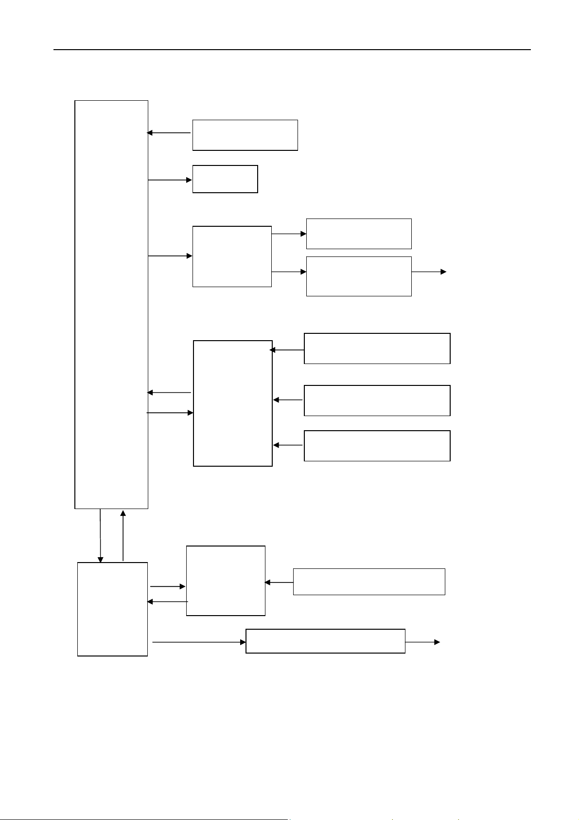
This section contains a functional description and detailed theory of operation of the equipment. A system
block diagram of the Controller is shown in Figure 3.2 and 3.3.
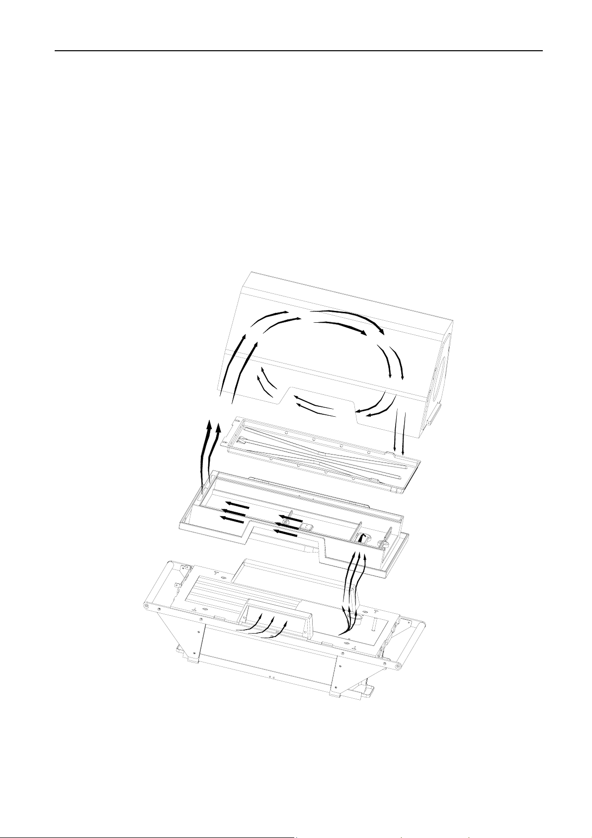
Temperature control can carry through the air-circulation system as figure 3.1. After the air outside is
purified and is filtrated, it can go into the constant temperature hood from the air-intake of the incubator through
the fan driving, and then recycle to the fan by place with a draught. All fresh and recycling air are led through
nearby the airflow sensor and heater. The air can pass through the sensor equipped with probe of temperature
sensor, which includes themistor of air temperature control and themistor of over-air-temp alarm.
FIGURE 3.1 AIR CIRCULATION SYSTEM
3-4
I6
SERVICE MANUAL FOR INCUBATOR EDITION/REVISION A/0
MAIN
MCU
Keypad control
Indicator
I/O control
A A
Fan motor checking
Temperature heater
control
ADC
Air Temperature sensor
Skin temperature sensor
Power voltage
AUXILIARY
MCU
B
ADC
Isolated temperature sensor
Temperature heater control
FIGURE 3.2 CONTROL DIAGRAM
3-5
I6
SERVICE MANUAL FOR INCUBATOR EDITION/REVISION A/0
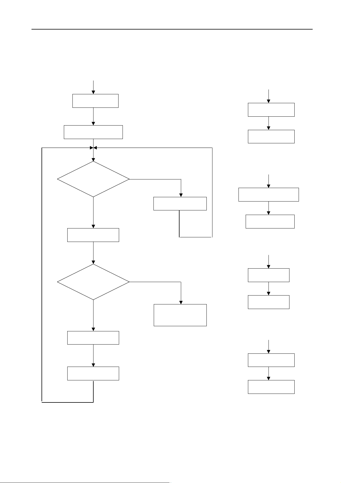
Start
INT1
Initialization
Data display
Key input
NO
Data handling
YES
Key handling
Real timer
Return
INT0
ADC Sampling
Return
Timer interruption
YES
Trouble checking
Timer
Return
Series port
NO
Heating control
Alarm
identification
Data display
Data transfer
Return
FIGURE 3.3 FLOW CHART OF PROGRAMME
3-6
I6

SERVICE MANUAL FOR INCUBATOR EDITION/REVISION A/0
3.2.2 Temperature Control
Temperature is regulated using either incubator Air or Skin temperature as the controlling parameter; the
desired mode is selected by the front panel keys.
In either mode of operation, the heater output is proportional to the amount of heat required to maintain
the desired temperature. In air mode,the air temperature can be maintained from 25 to 37ºC (over-ride mode:
37~38℃ ).A sensor located in the Sensor Module and compared with Air Set Temperature setting monitors
air temperature. The information from this sensor is supplied to heater control circuitry which regulates the
heater output to maintain the Air Temperature setting. In the event that over temperature limit is activated, the
heater is shut off. Under this control mode, skin display window will display the temperature on the skin
temperature sensor; if the skin temperature sensor isn’t inserted, the skin display window will display “--. -”.
In skin mode,the infant’s temperature can be selected from 34.0 to 37.0ºC (over-ride mode: 37~37.5
℃ ) .A temperature sensor is attached directly to the infant’s skin; the information from the sensor is supplied
to the heater control circuitry, which proportions the heater output to maintain the Skin Set Temperature. In Skin
Temperature Mode, the Skin Temperature will be displayed on Skin Temperature Display Window; the Air
Temperature Display Window will display the Air Temperature for information only. A second sensor within the
air temperature sensor serves as a backup to limit the maximum Incubator temperature. In the event that over
temperature limit is activated, the heater is shut off.
3.2.3 Alarms
Alarm is used for monitoring the temperature control system state. The system will check the state by the
alarm checkout procedure. When the checked data is abnormal, it will alarm. Table 3.2 listed alarm condition.
TABLE 3.2 ALARM
ALARM MESSAGE DESCRIPTION
Power Failure indicator is on
Code E0.1
If the mains power supply fails or no power supply, the power alarm with audible
and visu
In air mode, If short-circuit or open-circuit or bad connection occurs
on the air temperature sensor, at the same time, heater stops
working, press Silence/Reset Key to clear alarming for 5min,
please refer to the service part.
al will active.
If short-circuit or open-circuit or bad connection occurs on the isolated
Sensor Alarm
indicator is on
Code E0.2
Code E0.3
temper
ature sensor, at the same time, heater stops working, press Silence/Reset
Key to clear alarming for 5min, please refer to the service part.
If the deviation between the air temperature and isolated
temperature sensor is more than 0.8℃, at the s
stops working, press Silence/Reset Key to clear alarming for 5min,
please refer to the service part.
ame time, heater
3-7
I6

SERVICE MANUAL FOR INCUBATOR EDITION/REVISION A/0
TABLE 3.2 ALARM
ALARM MESSAGE DESCRIPTION
In baby mode, If short-circuit or open-circuit or bad connection occurs on the
Code E0.4
skin temper
Silence/Reset Key to clear alarming for 5min, please refer to the service part.
ature sensor, at the same time, heater stops working, press
Over-Temp
Alarm indicator
is on
Fan alarm
indicator is on
Sensor Alarm
indicator is on
HIGH Deviation
Alarm indicator
is on
Code E0.5
Code E0.6
Code E0.7
Code E0.8
Code E0.9
In the air mode, when the incubator temperature is less than 38 (set℃
temperature <37 ) or less than 40 (set temperature ℃℃>37 ), at ℃
the same time, heater stops working, press Silence/Reset Key to
clear alarming for 5min, it can not reset after clearing the failure,
press Silence/Reset Key to clear alarming
In the Baby mode, when the incubator temperature is less than 40 ,℃
at the same time, heater stops working, press Silence/Reset Key to
clear alarming for 5min, it can not reset after clearing the failure,
press Silence/Reset Key to clear alarming
When the fan motor stops working, at the same time, heater stops
working, press Silence/Reset Key to clear alarming for 5min, please
refer to the service part.
When the wind speed is lower than 1000rpm, at the same time, heater
stops working, press Silence/Reset Key to clear alarming for 5min,
please refer to the service part.
In baby mode, If the temperature of skin temperature sensor is always
lower 2℃ than the set temperature or more, heater stops working,
press Silence/Reset Key to clear alarming for 5min, it can reset
when the failure does not exist.
In air mode, If the air temperature is higher 3℃ than the set
temperature, heater stops working, press Silence/Reset Key to clear
alarming for 5min, it can reset when the failure does not exist.
In baby mode, If the skin temperature is higher 1℃ th
temperature, heater stops working, press Silence/Reset Key to clear
alarming for 5min, it can reset when the failure does not exist.
an the set
In air mode, If the air temperature is lower 3℃ than the set
temperature. At this time, the heater keeps working, press
LOW Deviation
Alarm indicator
is on
Low Voltage
Alarm
Indicator is on
Code E1.0
Code E1.1
Silence/Reset Key to clear alarming for 5min, it can reset when the
failure does not exist.
In baby mode, If the skin temperature is lower 1℃ than the
temperature, heater stops working, press Silence/Reset Key to clear
alarming for 5min, it can reset when the failure does not exist.
The incubator 12V dc power source or the battery supplies below 10.5V and/or
24V DC po
working, press Silence/Reset Key to clear alarming for 5min,
please refer to the service part.
wer source supply below 22.5V,
at the same time, heater stops
set
3-8
I6

SERVICE MANUAL FOR INCUBATOR EDITION/REVISION A/0
TABLE 3.2 ALARM
ALARM MESSAGE DESCRIPTION
The system
indicator is
on
Code H0.1
CodeH0.2
Code H0.3
Code H0.4
Code H0.5
Code H0.6
Code H0.7
Code H0.8
ROM inside of the main MCU failed, at the same time, heater stops working, press
Silence/
Reset Key to clear alarming for 5min, please refer to the service part.
If the internal system of main MCU is error, at the same time, heater stops
g, press Silence/Reset Key to clear alarming for 5min, please refer to the
workin
service part.
If the communication between the main MCU and the auxiliary MCU A is error, at
me time, heater stops working, press Silence/Reset Key to clear alarming
the sa
for 5min, please refer to the service part.
ROM inside of the auxiliary MCU failed, at the same time, heater stops working,
press Si
lence/Reset Key to clear alarming for 5min, please refer to the service
part.
If the internal system of auxiliary MCU is error, at the same time, heater stops
g, press Silence/Reset Key to clear alarming for 5min, please refer to the
workin
service part.
2
PROM inside of the main controller failed, at the same time, heater stops
E
working, press Silence/Reset Key to clear alarming for 5min, please refer to the
service part.
ADC failure outside main MCU (e.g., auxiliary system TLV2548, including wrong
chip damage, no response and so on).at the same time, heater stops
sample,
working, press Silence/Reset Key to clear alarming for 5min, please refer to the
service part.
ADC failure outside auxiliary MCU (e.g., auxiliary system TLV2548, including
sample, chip damage, no response and so on).at the same time, heater
wrong
stops working, press Silence/Reset Key to clear alarming for 5min, please refer to
the service part.
I6
Heating electric circuit failure (e.g. heating device, solid relay, mechanism relay
Code H0.9
and their s
working, press Silence/Reset Key to clear alarming for 5min, please refer to the
eprate controlling circuit failure). At the same time, heater stops
service part.
Power voltage overlarge failure (when the power supply for the battery larger
than 15.5V, for DC12V larger than 14.5V or for DC24V is larger than 28.5V,
Code H1.0
and the output voltage for power switch is larger than 17.0V).
At the same time,
heater stops working, press Silence/Reset Key to clear alarming for 5min, please
refer to the service part.
Short circuit happens when pressing keys on keyboard, at the same time, heater
Code H1.1
stops wor
king, press Silence/Reset Key to clear alarming for 5min, please refer to
the service part.
Battery failure. The rechargeable battery inside of the controller nconne cted,
Code H1.2
dropped or short-circuit failure.
At the same time, heater stops working, press
Silence/Reset Key to clear alarming for 5min, please refer to the service part.
When there is malfunction in the connecting parts between the storage battery
Code H1.3
and the powe
Key to clear alarming for 5min, please refer to the service part.
r box, at the same time, heater stops working, press Silence/Reset
3-9
Loading...