

Davey Nipper DNP15C, Nipper DNP25C, Nipper DNP35C, Nipper DNP15CLS, Nipper DNP25CLS Installation And Operating Instructions Manual
Page 1

Salt Pool Chlorination System
Nipper
™
ChloroMatic
Models: DNP15C, DNP25C, DNP35C,
DNP15CLS & DNP25CLS
Installation and Operating
Instructions
WARNING: Failure to follow these instructions and comply with all applicable
codes may cause serious bodily injury and/or property damage.
The installation of this product should be carried out by a person knowledgeable
in swimming pool plumbing requirements following the installation instructions
provided in this manual.
Please pass these instructions on to the operator of this equipment.
Page 2

Nipper
™
ChloroMatic
Congratulations! You are now the proud owner of a new ChloroMatic Nipper. Please read all information in
this manual carefully before installing or operating your ChloroMatic Nipper.
Contents:
PACKING LIST ..................................................................................................................................................3
IMPORTANT SAFETY INSTRUCTIONS ...........................................................................................................4
COMMON TERMS ............................................................................................................................................6
INSTALLING THE ChloroMatic Nipper ..............................................................................................................6
CONNECTING THE ELECTROLYTIC CELL TO THE POWER SUPPLY .........................................................7
CONNECTING THE FLOW SWITCH TO THE CELL HOUSING ......................................................................7
PRE-START UP PROCEDURE .........................................................................................................................8
OPERATION OF YOUR ChloroMatic Nipper ....................................................................................................8
CONTROL PANEL .............................................................................................................................................9
INITIAL START-UP ............................................................................................................................................9
TYPICAL (EVERYDAY) START-UP .................................................................................................................15
Nipper FEATURES ..........................................................................................................................................16
MAINTENANCE OF POWER SUPPLY ...........................................................................................................35
MAINTENANCE OF THE ELECTROLYTIC CELL ..........................................................................................35
DAY TO DAY OPERATION ..............................................................................................................................36
CHLORINE PRODUCTION .............................................................................................................................38
GENERAL INFORMATION ..............................................................................................................................39
TROUBLE SHOOTING ...................................................................................................................................39
SPARE PARTS ................................................................................................................................................40
2
Page 3
1. PACKING LIST
1 x
1 x
1 x
1 x
1 x
1 x
2 x
Nipper
™
ChloroMatic
Models: DNP15C, DNP25C, DNP35C, DNP15CLS & DNP25CLS
Quick Reference Guide
Salt Pool Chlorination System
1 x
1 x
1 x
1 x
1 x
1 x
2 x
Nipper
™
ChloroMatic
Models: DNP15C, DNP25C, DNP35C, DNP15CLS & DNP25CLS
Quick Reference Guide
Salt Pool Chlorination System
www.bit.ly/nippercm
S
a
lt Pool
Ch
lor
in
ation
Syst
em
M
o
del
s
:
D
N
P15C
,
D
N
P25C
,
D
N
P
35
C
,
D
N
P15C
LS
&
D
N
P25C
LS
In
sta
l
lation
an
d
Operatin
g
In
stru
ct
i
on
s
The
i
ns
t
a
lla
t
ion of
t
his
pr
oduc
t
s
hould
be
c
a
r
r
ie
d out
by
a
p
e
r
s
on k
nowle
dge
a
ble
in s
wim
m
ing pool plum
bing r
e
quir
e
m
e
nt
s
f
ollowing t
he
ins
t
a
lla
t
ion ins
t
r
uc
t
ions
pr
ov
ide
d in t
his
m
a
nua
l.
W
A
R
N
IN
G:
Fa
ilur
e
t
o f
ollow t
he
s
e
ins
t
r
uc
t
ions
a
nd c
om
ply
wit
h a
ll
a
pplic
a
ble
c
ode
s
m
a
y
c
a
us
e
s
e
r
ious
bodily
injur
y
a
nd/or
pr
ope
r
t
y
da
m
a
ge
.
Pl
eas
e
p
a
s
s
t
hes
e
i
ns
t
r
uc
t
i
o
ns
o
n
t
o
t
he
o
p
er
at
o
r
o
f
t
hi
s
e
q
ui
p
m
ent
.
Nipper
™
C
h
l
o
r
o
Mati
c
www.bit.ly/nippercm
Salt Pool Chlorination System
Models:
Installation and Operating
The installation of this product should be carried out by a person knowledgeable
in swimming pool plumbing requirements following the installation instructions
provided in this manual.
WARNING: Failure to follow these instructions and comply with all applicable
codes may cause serious bodily injury and/or property damage.
Please pass these instructions on to the operator of this equipment.
Nipper
™
ChloroMatic
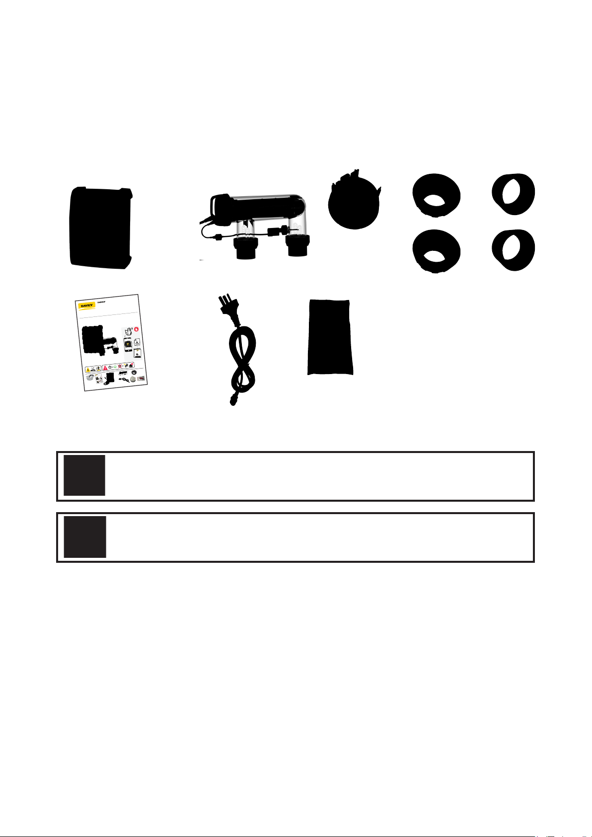
Included with your ChloroMatic Nipper are the following items, please check the contents of the box carefully
prior to attempting to install the system:
a. 1 x Power supply with cell lead;
b. 1 x U-shaped electrolytic housing & cell;
c. 1 x Cell blanking cap & o-ring;
d. 2 x Barrel unions including nut, tail & o-ring;
a
b c d e
e. 2 x Reducing bushes;
f. 1 x Quick reference guide;
g. 1 x Power lead; and
h. 1 x Mounting screws & plugs pack
f g h
DNP15C, DNP25C, DNP35C,
DNP15CLS & DNP25CLS
Instructions
Figure 1.1
ATTENTION: Your ChloroMatic Nipper is not intended for use by young children or
inrm persons without supervision. Please ensure that young children are supervised
to ensure that they do not play with the ChloroMatic Nipper System.
ATTENTION:
Power connections and wiring must be carried out by an authorised electrician.
3
Page 4
2. IMPORTANT SAFETY INSTRUCTIONS
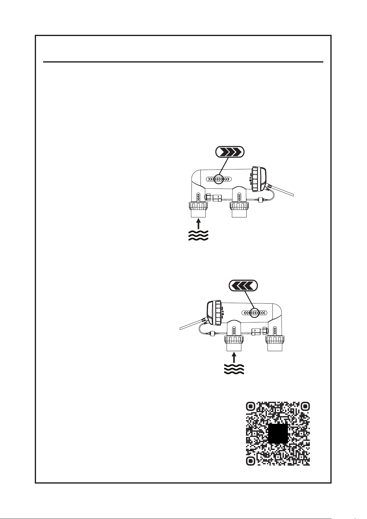
• To minimise the risk of gas build-up in the cell housing, you must ensure there is sufcient
water ow through the cell when the unit is on and producing chlorine.
• It is essential that your pool pump circulates sufcient water through the cell housing to
completely ll the cell housing with water during the chlorination process.
• Periodically check the paddle of the safety ow switch to ensure it is free to move back and
forth and that the lock nut is done up hand tight.
ü
Diagram A
CORRECT OPERATION
WITH A PUMP RUNNING
Figure 2.1
û
Diagram B
INCORRECT OPERATION
WITH A PUMP RUNNING
• Always check for the latest versions of installation and
operation instructions that support these products.
Simply scan this QR code, or go to: www.bit.ly/nippercm
4
Figure 2.2
Page 5

IMPORTANT INFORMATION
ABOUT YOUR Nipper
FACTORS THAT WILL IMPROVE THE PERFORMANCE & LIFE OF YOUR ChloroMatic Nipper.
PLEASE READ THIS BEFORE OPERATING YOUR CHLORINATOR
POOL BUILDERS:
Please cover this information with your customer during the new pool “Handover Session”.
Chlorinators are a valuable piece of pool equipment and must be cared for to get the best
performance and life span. There are THREE main factors that will damage your ChloroMatic
Nipper and reduce the life of the product. Please monitor the following factors in accordance
with your installation & operating instructions.
1. MAINTAIN RECOMMENDED SALT LEVELS
RECOMMENDED OPERATING RANGE: (see page 38)
• Run your ChloroMatic Nipper at the salt levels stated within this document and on the
product to ensure optimum performance and cell life;
• Operating the ChloroMatic Nipper at low salt levels will damage the cell and reduce its life;
•ThecontrolpaneldisplaysaashingredLEDindicatorwarningwhenthesaltlevels
are low;
• If no action is taken to rectify the salt levels, damage to the cell may result which will
not be covered under warranty.
2. MONITOR & MAINTAIN YOUR Nipper CELL
Nipper has a “reverse polarity” cell.
• To keep your ChloroMatic Nipper in the best possible condition, regular monitoring of the cell
is recommended. The cell is in the clear plastic housing and contains the Titanium plates.
• During the chlorination process a white powdery Calcium scale may naturally build up
on the Titanium plates in the cell. Monitor the cell to prevent excessive scale build up.
Excessive scale build-up will cause damage to your cell, and dramatically reduce its
efciencyandlifespan.
• The control panel displays a red LED indicator warning that indicates that the cell may
require cleaning.
• If Calcium scale builds up please clean the cell, following the cleaning instructions provided
on page 36.
• NEVER: Use concentrated acid to clean your cell.
• NEVER: Leave cell in cleaning solution for extended periods of time.
• NEVER: Use metal implements, scourers, or brushes to clean the cell.
3. BALANCED POOL WATER CHEMISTRY
• Correct salt levels MUST be maintained (see page 38) for optimum performance and lifespan.
• Calcium Hardness levels MUST be kept to ideal ranges of 200 - 275ppm (for Concrete
and Tiled Pools) and 100 - 225ppm (for other surfaces) to prevent excessive scale build up
and damage to equipment.
• pH levels MUST be kept to ideal levels to prevent damage to equipment and pool surfaces
and to obtain optimum chlorination effectiveness.
• Total Alkalinity and Stabiliser levels must also be kept in an ideal range.
Note: Please refer to the POOL WATER CHEMISTRY chart on page 40 for more information.
5
Page 6
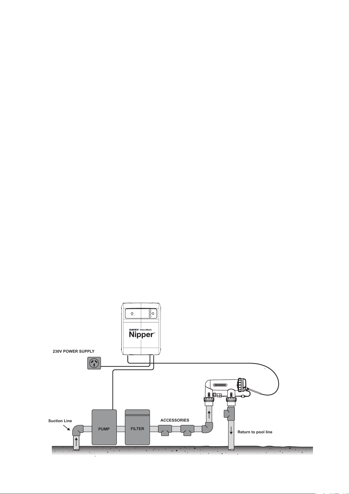
3. COMMON TERMS
Return to pool line
Suction Line
FILTER
PUMP
ACCESSORIES
230V POWER SUPPLY
Algae Microscopic forms of plant life which enter the pool by rain, wind and dust. There are
numerous varieties – some are free floating whilst others grow on walls and in cracks
and come in different colours. Some are more resistant to chemical treatment than others.
Bacteria The germs that contaminate your pool. Introduced by swimmers, dust, rain storms
and other elements.
Balanced water The correct ratio of mineral content and pH level that prevents pool water from being
corrosive or scale forming.
Chloramines Compounds formed when chlorine combines with nitrogen from urine, perspiration, etc.
Chloramines cause eye and skin irritation, as well as unpleasant odours.
Chlorine demand The chlorine required to destroy germs, algae and other contaminants in the pool.
Chlorine residual The amount of chlorine remaining after chlorine demand has been satisfied.
This is the reading obtained with your test kit.
Cyanuric acid Also known as stabiliser or conditioner. It reduces dissipation of chlorine by direct
sunlight.
Liquid acid Chemical used to reduce the pH and total alkalinity in the pool water, and for cleaning
Sanitiser cell.
ppm An abbreviation for Parts Per Million the accepted measurement of chemical
concentration in swimming pool water. 1 ppm = 1 mg/L.
4. INSTALLING THE Nipper
4.1 INSTALLING THE POWER SUPPLY
Select a convenient well-ventilated location within one metre of filter equipment and mount the power
supply vertically onto a wall, or post at least as wide as the ChloroMatic Nipper power supply itself. Davey
recommends that the power supply shall not be located within 3 meters of the pool water. Plug pump and
chlorinator power supply into a suitable weatherproof power outlet/controller. Where applicable, some
model variants have a 3-pin socket on the underside of the power supply, provide pump power. The unit
must be kept away from acid and other chemical storage areas. Acid and chemical vapours will corrode the
electronics inside the unit. It must also be kept away from heat sources. Good ventilation is necessary for
correct operation.
Two self-tapping screws and wall plugs have been provided for fast and simple installation.
Use a 6mm masonry drill bit when fitting Power Supply to a brick or concrete wall. When mounting to a post
drill pilot holes and fit screws provided. Holes should be level and 164mm apart. Once screws are in position
simply hang ChloroMatic Nipper power supply via mounts on back of Unit.
Figure 4.1
6
Page 7
4.2 INSTALLING THE CELL
The ChloroMatic Nipper cell should always by the last appliance in your system. Ensure the cell is installed
after pumps, filters and any heating appliances. To achieve best efficiency, the ChloroMatic Nipper cell should
be installed such that turbulent water is limited as much as possible. When installing a 90° elbow before the
cell’s inlet barrel union, ensure there’s equivalent to 5 x pipe diameter of straight pipe between the elbow and
the union. That is, if the pipe diameter is 40mm, straight pipe entering the barrel union should be no less than
200mm in length. Isolation valves (used where equipment is located below pool water level) should also be
installed no closer than 5 x pipe diameter from the inlet barrel union. This will assist laminar flow.
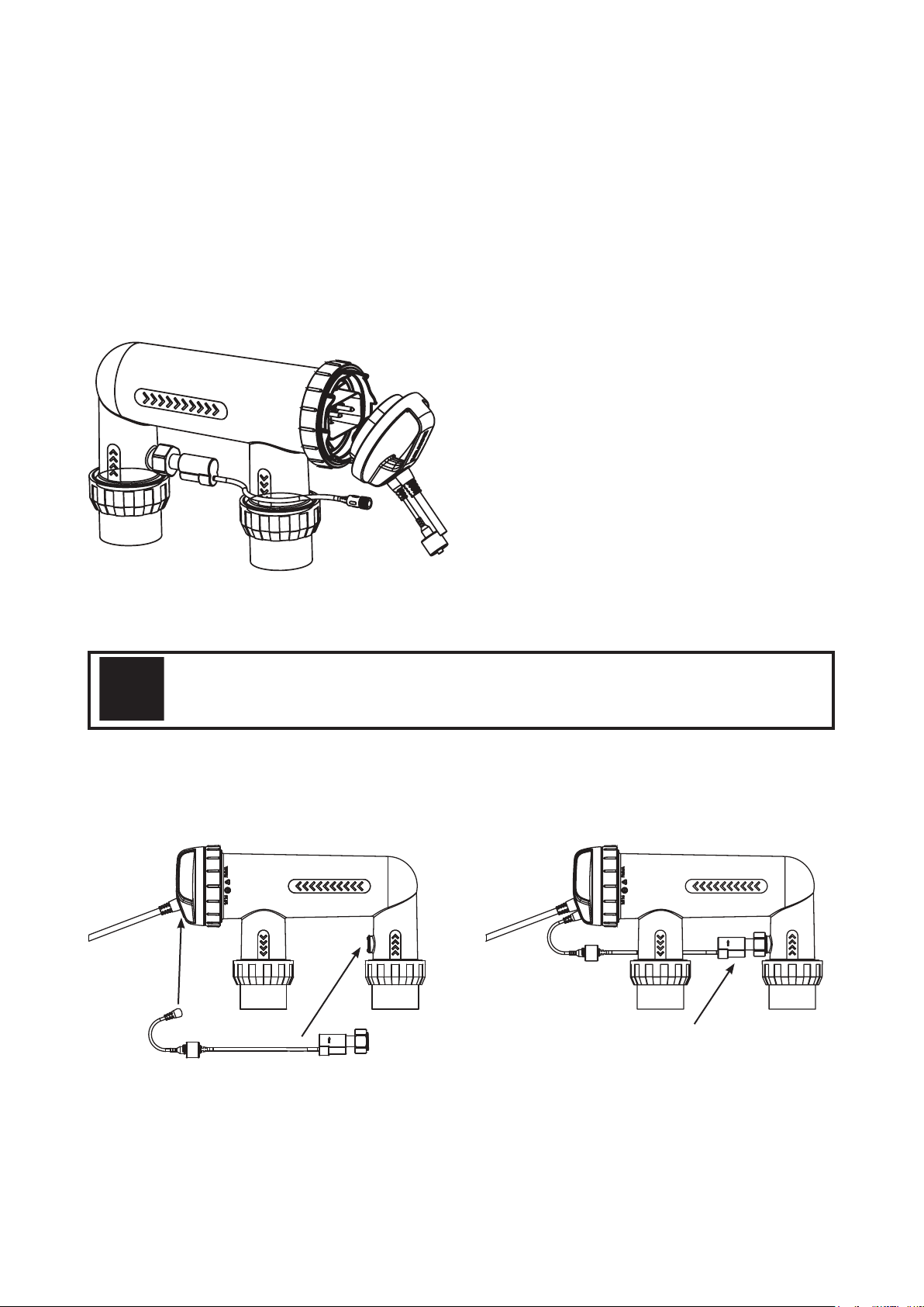
5. CONNECTING THE ELECTROLYTIC CELL TO THE POWER SUPPLY
The Nipper salt water sanitiser uses a reverse polarity electrolytic cell for low maintenance operation. The
ChloroMatic Nipper power supply is fitted with a flexible lead terminated with the cell connectors built into a
plastic moulding. The three in-line connectors are not “polarity sensitive”.
Figure 5.1
NOTE: The ChloroMatic Nipper cell is supplied with a paddle type flow switch, which is to be installed
on the cell as shown in the diagram on page 4 and connected to the cell lead via the connector on
the end of the cable.
IMPORTANT: The ow switch must be mounted with the highlighted arrow on side of
the switch pointing in the direction of ow.
6. CONNECTING THE FLOW SWITCH TO THE CELL HOUSING
Ensure that the flow switch is installed into the cell housing.
Ensure the flow switch direction is correct (see page 4)
Fitted
Figure 6.1 Figure 6.2
7
Page 8
7. PRE-START UP PROCEDURE
Before operating your ChloroMatic Nipper salt pool chlorination system, please ensure the following quantity
of pool salt has been added to your pool.
• POOL SALT:
To raise salt
concentration by
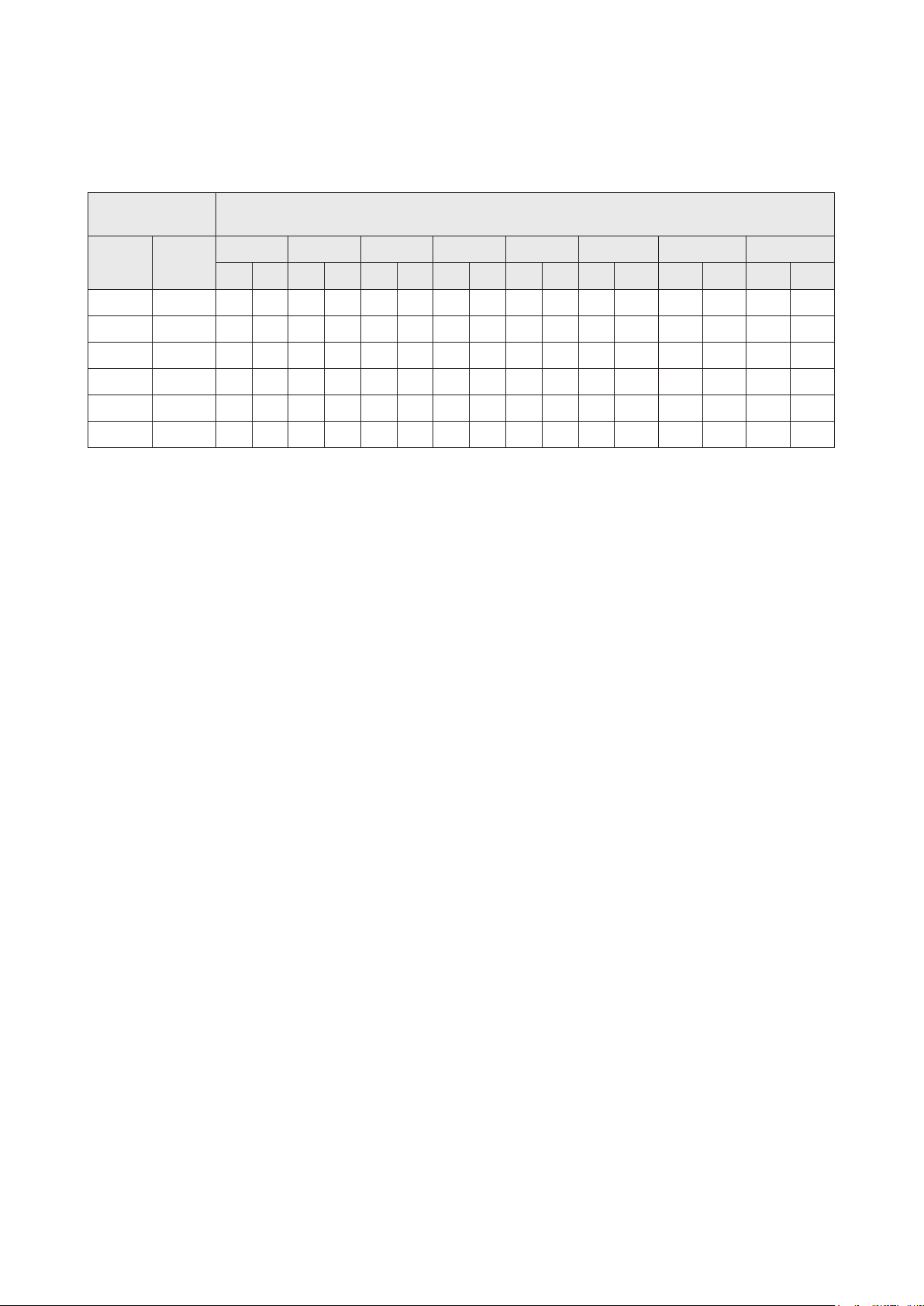
30,000L 40,000L 50,000L 60,000L 70,000L 80,000L 90,000L 100,000L
ppm %
kg lbs kg lbs kg lbs kg lbs kg lbs kg lbs kg lbs kg lbs
1,000 0.1 30 66 40 88 50 110 60 132 70 154 80 176 90 198 100 220
2,000 0.2 60 132 80 176 100 220 120 265 140 309 160 353 180 397 200 441
3,000 0.3 90 198 120 265 150 331 180 397 210 463 240 529 270 595 300 661
4,000 0.4 120 265 160 353 200 441 240 529 280 617 320 705 360 794 400 882
5,000 0.5 150 331 200 441 250 551 300 661 350 772 400 882 450 992 500 1,102
6,000 0.6 180 397 240 529 300 661 360 794 420 926 480 1,058 540 1,190 600 1,323
• CHLORINE: For a new pool installation that has not been chlorinated, add sufficient Chlorine (liquid or
granular) to achieve a reading of 3 ppm (with a suitable test kit). Alternatively, run the ChloroMatic Nipper salt
pool chlorination system continuously on BOOST MODE, for approximately 24 hours, or until a reading of 3
ppm is reached.
• STABILISER: It is essential that pool stabiliser be added and maintained at the rate of 25 - 50 ppm at
all times (FOR OUTDOOR POOLS ONLY). For ORP controlled systems the stabiliser level should be
maintained between 15-25ppm.
• (Refer Day to Day Operation page 36 for further information).
Salt required
8. OPERATION OF YOUR Nipper
CHLORINE OUTPUT is expressed as a percentage. Set the ChloroMatic Nipper to the percentage output
required and the unit will automatically adjust the cell output to the set level. The ChloroMatic Nipper is fitted
with an electronic control and warning system. This regulates the output of the ChloroMatic Nipper to the
pre-set maximum and changes cell polarity as indicated by the + or – on the digital display. The polarity will
alternate over a number of hours of chlorination time, not necessarily pump-run hours. The warning system
consists of one Operation LED which will glow green to indicate normal operation, or red to indicate user
attention required, see troubleshooting on page 38.
8
Page 9
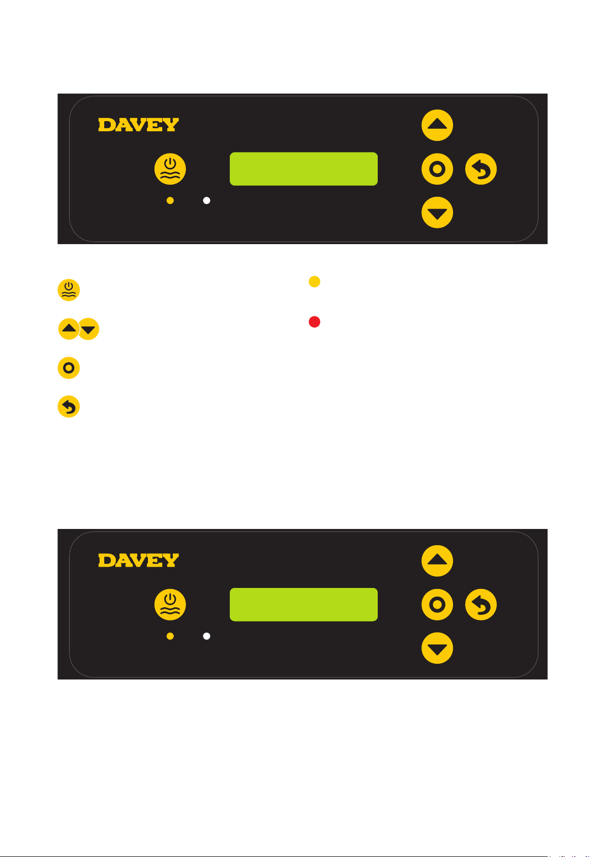
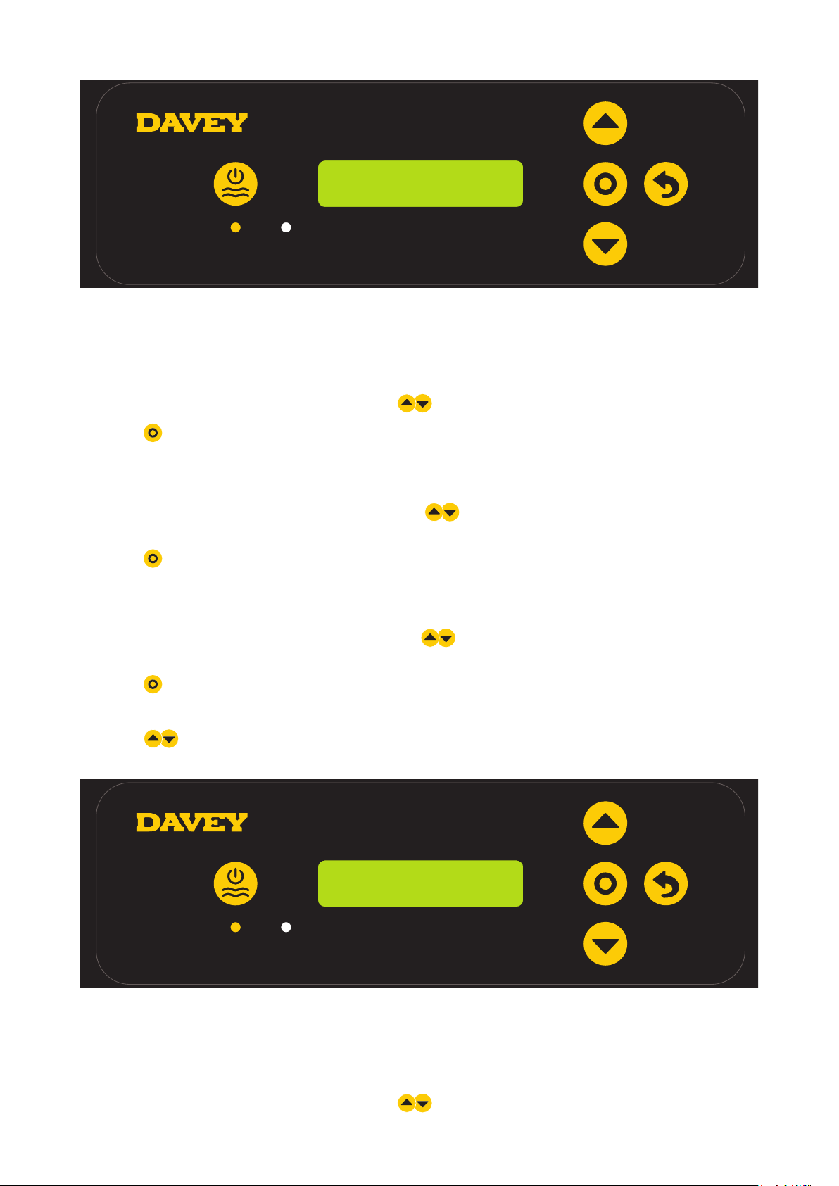
9. CONTROL PANEL
9.1 LAYOUT
Figure 9.1
Manual on/off
100% – 09:29 AM
auto ON
Power indicator
(lit when Nipper on)
Menu up/down
Menu/setting select
Menu/setting cancel (go back)
Alarm indicator
(asheswhenalarmactive)
Time out
(whenever device is left for 30 seconds
without input from user, settings are saved,
and home screen displayed)
10. INITIAL START-UP
Once the salt level in the pool is correct the unit may be switched on.
Note: Once the unit starts there is a short time delay until the cell operates to ensure the filtration
system is primed with water.
• The first time the ChloroMatic Nipper is turned on, the following screen is shown on start-up:
DAVEY
V1.2.3 AU 15
Figure 10.1
> This screen shows the version of software (ie v1.2.1 shown) and your model of ChloroMatic Nipper
(ie AU 15 shown, meaning DNP15C).
• The display then automatically reverts to the following screen:
9
Page 10
3. LANGUAGE
3. LANGUAGE
ENGLISH
ENGLISH
Figure 10.2
> This screen shows the language menu and the current language setting (ie English shown);
> The language setting can be changed by pressing the
available languages;
> Press
> If a mistake is made, the setting can be changed later.
• The display then automatically reverts to the following screen:
menu/setting select once your preferred language is displayed;
menu up/down buttons to scroll through
4. TIME FORMAT
12HR
Figure 10.3
> This screen shows the time format menu and the current time format (ie 12HR shown);
> The time format can be changed by pressing the
and 24HR formats;
menu up/down buttons to toggle between 12HR
> Press
> If a mistake is made, the setting can be changed later.
• The display then automatically reverts to the following screen:
menu/setting select once your preferred time format is displayed;
1. CLOCK
07:34 PM
Figure 10.4
> This screen shows the clock’s current time (ie 07:34PM shown);
> Initially the clock hours will be flashing;
10
Page 11
> The clock hours can be changed by pressing the
menu up/down buttons to scroll to your chosen time;
> Press
> If a mistake is made, the setting can be changed later.
> Next the clock minutes will be flashing;
> The clock minutes can be changed by pressing the
> Press
> If a mistake is made, the setting can be changed later.
> Next the clock AM/PM will be flashing;
> The clock AM/PM can be changed by pressing the
AM and PM;
> Press
> If a mistake is made, the setting can be changed later.
• The display then automatically reverts to the following screen:
menu/setting select once your preferred clock hour is displayed;
menu up/down buttons to scroll to your chosen time;
menu/setting select once your preferred clock minutes is displayed;
menu up/down buttons to toggle between
menu/setting select once your preferred clock AM/PM is displayed;
2. DATE
01 JAN 2000
Figure 10.5
> This screen shows the date format menu and the current date (ie 01 JAN 2000 shown);
> Initially the date day will be flashing;
> The date day can be changed by pressing the
chosen date day;
> Press
> If a mistake is made, the setting can be changed later.
> Next the date month will be flashing;
> The date month can be changed by pressing the
date month;
> Press
> If a mistake is made, the setting can be changed later.
> Next the date year will be flashing;
> The date year can be changed by pressing the
date year;
> Press
> If a mistake is made, the setting can be changed later.
menu/setting select once your preferred date day is displayed;
menu/setting select once your preferred date month is displayed;
menu/setting select once your preferred date year is displayed;
menu up/down buttons to scroll to your
menu up/down buttons to scroll to your chosen
menu up/down buttons to scroll to your chosen
• The display then automatically reverts to the HOME screen:
11
Page 12
TIMER 1
ON 06:00 AM
Figure 10.6
> The screen shows the ON-TIME of TIMER 1:
■ current ON-TIME of TIMER 1 is 6:00am.
> Initially the clock hours will be flashing;
> The clock hours can be changed by pressing the
> Press
> If a mistake is made, the setting can be changed later;
> Next, the clock minutes will be flashing;
> The clock minutes can be changed by pressing the
chosen time;
> Press
> If a mistake is made, the setting can be changed later;
> Next, the clock AM/PM will be flashing;
> The clock AM/PM can be changed by pressing the
between AM and PM;
> Press
> If a mistake is made, the setting can be changed later;
> Press
• The display then automatically reverts to the following screen:
menu/setting select once your preferred clock hour is displayed;
menu/setting select once your preferred clock minutes is displayed;
menu/setting select once your preferred clock AM/PM is displayed;
menu up/down buttons
menu up/down buttons to scroll to your chosed time;
menu up/down buttons to scroll to your
menu up/down buttons to toggle
TIMER 1
OFF 09:00 AM
Figure 10.7
> The screen shows the OFF-TIME of TIMER 1:
■ current OFF-TIME of TIMER 1 is 9:00am.
> Initially the clock hours will be flashing;
> The clock hours can be changed by pressing the
menu up/down buttons to scroll to your chosed time;
12
Page 13
> Press
> If a mistake is made, the setting can be changed later;
> Next, the clock minutes will be flashing;
menu/setting select once your preferred clock hour is displayed;
> The clock minutes can be changed by pressing the
chosen time;
> Press
> If a mistake is made, the setting can be changed later;
> Next, the clock AM/PM will be flashing;
> The clock AM/PM can be changed by pressing the
between AM and PM;
> Press
> If a mistake is made, the setting can be changed later;
• The display then automatically reverts to the following screen:
menu/setting select once your preferred clock minutes is displayed;
menu/setting cancel (go back) button once your preferred OFF-TIME for TIMER 1 is displayed;
menu up/down buttons to scroll to your
menu up/down buttons to toggle
TIMER 2
ON 05:00 PM
Figure 10.8
> The screen shows the ON-TIME of TIMER 2:
■ current ON-TIME of TIMER 2 is 5:00pm.
> Initially the clock hours will be flashing;
> The clock hours can be changed by pressing the
> Press
> If a mistake is made, the setting can be changed later;
> Next, the clock minutes will be flashing;
> The clock minutes can be changed by pressing the
chosed time;
> Press
> If a mistake is made, the setting can be changed later;
> Next, the clock AM/PM will be flashing;
> The clock AM/PM can be changed by pressing the
between AM and PM;
> Press
menu/setting select once your preferred clock hour is displayed;
menu/setting select once your preferred clock minutes is displayed;
menu/setting select once your preferred clock AM/PM is displayed;
menu up/down buttons to scroll to your chosen time;
menu up/down buttons to scroll to your
menu up/down buttons to toggle
> If a mistake is made, the setting can be changed later;
• The display then automatically reverts to the following screen:
13
Page 14
TIMER 2
OFF 10:00 PM
Figure 10.9
> The screen shows the OFF-TIME of TIMER 2:
■ current OFF-TIME of TIMER 2 is 10:00pm.
> Initially the clock hours will be flashing;
> The clock hours can be changed by pressing the
> Press
> If a mistake is made, the setting can be changed later;
> Next, the clock minutes will be flashing;
> The clock minutes can be changed by pressing the
chosed time;
> Press
> If a mistake is made, the setting can be changed later;
> Next, the clock AM/PM will be flashing;
> The clock AM/PM can be changed by pressing the
between AM and PM;
> Press
> If a mistake is made, the setting can be changed later;
• The display then automatically reverts to the HOME screen:
menu/setting select once your preferred clock hour is displayed;
menu/setting select once your preferred clock minutes is displayed;
menu/setting cancel (go back) button once your preferred OFF-TIME for TIMER 1 is displayed;
menu up/down buttons to scroll to your chosen time;
menu up/down buttons to scroll to your
menu up/down buttons to toggle
100% – 07:31 AM
AUTO ON
Figure 10.10
> This screen shows the:
■ current chlorine output setting (ie 100% shown);
■ current time setting;
■ current power status (ie ON shown).
14
Page 15

11. TYPICAL (EVERYDAY) START-UP
Note: Once the unit starts there is a short time delay until the cell operates to ensure the filtration
system is primed with water.
• Every time the ChloroMatic Nipper is turned on, the following screen is shown on start-up:
DAVEY
V1.2.1 EU 15L
Figure 11.1
• The display then automatically reverts to the HOME screen:
100% – 07:31 AM
AUTO ON
Figure 11.2
> This screen shows the:
■ current chlorine output setting (ie 100% shown);
■ current time setting;
■ current power status:
AUTO ON: (ie as shown above) indicates the ChloroMatic Nipper is currently operating within the
ON-TIME of either TIMER 1, or TIMER 2;
AUTO: indicates the ChloroMatic Nipper is powered but is within the OFF-TIME of both
TIMER 1, and TIMER 2;
MANUAL ON: indicates the ChloroMatic Nipper is currently operating, having been manually overridden;
OFF: indicates the ChloroMatic Nipper is powered but is not currently operating, having been
manually overridden.
15
Page 16

12. ChloroMatic Nipper FEATURES
12.1 CONTROLLING CHLORINE OUTPUT
65% – 09:35 AM
AUTO 0N
Figure 12.1
The CHLORINE OUTPUT controls the time that the cell is producing chlorine, as a percentage of total time that
the ChloroMatic Nipper is on. If the ChloroMatic Nipper cell is producing, it is producing at 100%, unless otherwise
altered (see sections WINTER MODE, or SPA MODE). The cell run time is referred to as “cell duty cycle”.
For example:
• If the ChloroMatic Nipper is on for 8 hours per day, and the CHLORINE OUTPUT is set to 50%: the
ChloroMatic Nipper cell duty cycle is only 4 hours, of that day;
• If the ChloroMatic Nipper is on for 8 hours per day, and the CHLORINE OUTPUT is set to 25%: the
ChloroMatic Nipper cell duty cycle is only 2 hours, of that day.
To adjust the CHLORINE OUTPUT:
70% – 09:35 AM
CHLORINE OUTPUT
Figure 12.2
> Press the menu up/down buttons to scroll to your chosen CHLORINE OUTPUT;
> The setting will change the cell duty cycle by 5% increments;
> Press
> This will then take you back to the HOME screen.
menu/setting select once your preferred CHLORINE OUTPUT is displayed;
16
Page 17

12.2 AUTOMATED TIMERS
The ChloroMatic Nipper has two separate timers available for automated operation. This is ideal if looking to run
the pool a few hours in the morning, then a few hours in the afternoon. It is important to ensure that the timers do
not overlap as this may create confusion when the timer turns on and off.
To adjust ON-TIME of TIMER 1:
70% – 09:35 AM
CHLORINE OUTPUT
Figure 12.3
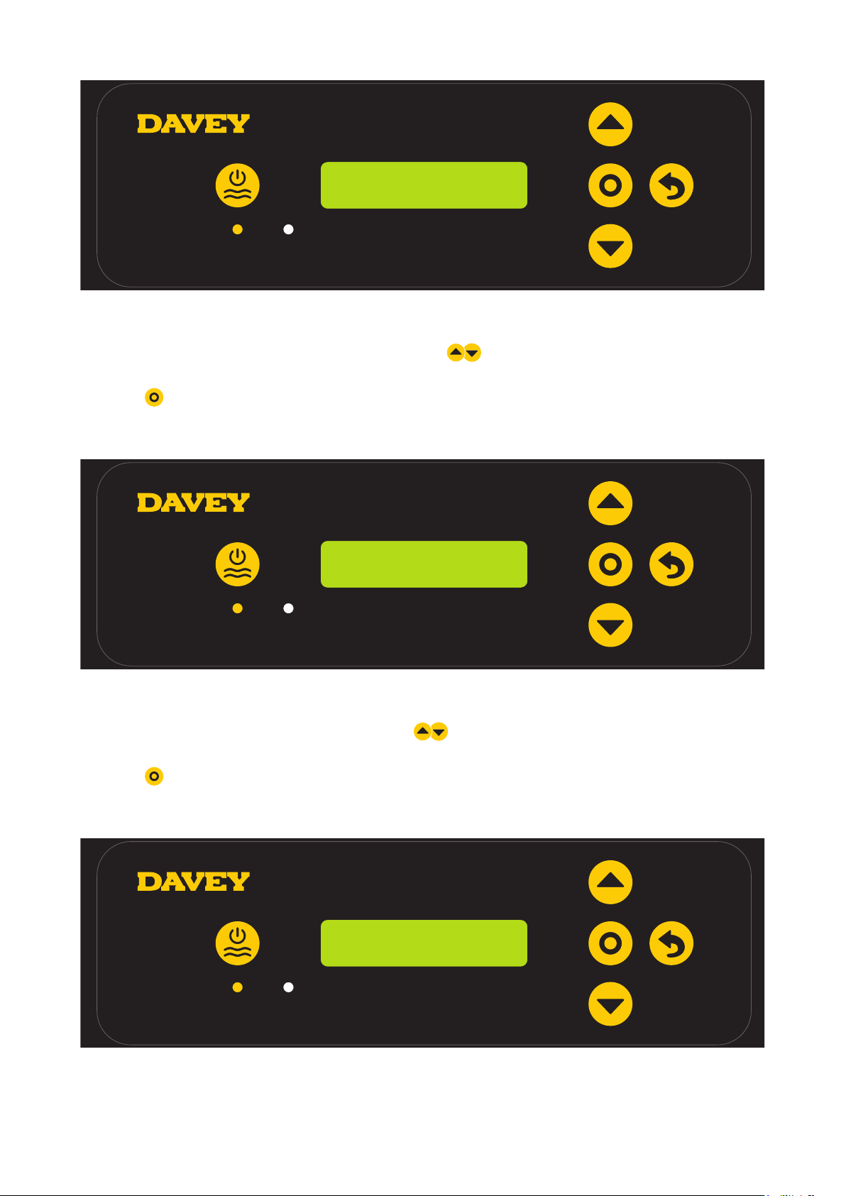
> From the HOME screen, press menu/setting select;
> The display will show this screen:
MODE
1. TIMER 1
Figure 12.4
> From this screen, press menu/setting select to enter TIMER 1 menu;
TIMER 1
ON 06:00 AM
Figure 12.5
> The screen shows the ON-TIME of TIMER 1:
■ current ON-TIME of TIMER 1 is 6:00am.
> Initially the clock hours will be flashing;
> The clock hours can be changed by pressing the
> Press
menu/setting select once your preferred clock hour is displayed;
menu up/down buttons to scroll to your chosen time;
17
Page 18

> If a mistake is made, the setting can be changed later;
> Next, the clock minutes will be flashing;
> The clock minutes can be changed by pressing the
chosed time;
> Press
> If a mistake is made, the setting can be changed later;
> Next, the clock AM/PM will be flashing;
> The clock AM/PM can be changed by pressing the
between AM and PM;
> Press
> If a mistake is made, the setting can be changed later;
> Press
This will take you back to the HOME SCREEN.
To adjust OFF-TIME of TIMER 1:
menu/setting select once your preferred clock minutes is displayed;
menu/setting select once your preferred clock AM/PM is displayed;
menu/setting cancel (go back) button once your preferred ON-TIME for TIMER 1 is displayed.
70% – 09:35 AM
CHLORINE OUTPUT
menu up/down buttons to scroll to your
menu up/down buttons to toggle
Figure 12.6
> From the HOME screen, press menu/setting select;
> The display will show this screen:
MODE
1. TIMER 1
Figure 12.7
> From this screen, press menu/setting select to enter TIMER 1 menu;
18
Page 19

TIMER 1
ON 06:00 AM
Figure 12.8
> Using the menu up/down buttons scroll to the OFF-TIME of TIMER 1.
TIMER 1
OFF 09:00 AM
Figure 12.9
> The screen shows the OFF-TIME of TIMER 1:
■ current OFF-TIME of TIMER 1 is 9:00am.
> Initially the clock hours will be flashing;
> The clock hours can be changed by pressing the
> Press
> If a mistake is made, the setting can be changed later;
> Next, the clock minutes will be flashing;
> The clock minutes can be changed by pressing the
chosed time;
> Press
> If a mistake is made, the setting can be changed later;
> Next, the clock AM/PM will be flashing;
> The clock AM/PM can be changed by pressing the
between AM and PM;
> Press
displayed;This will take you back to the HOME SCREEN.
menu/setting select once your preferred clock hour is displayed;
menu/setting select once your preferred clock minutes is displayed;
menu/setting cancel (go back) button once your preferred OFF-TIME for TIMER 1 is
menu up/down buttons to scroll to your chosen time;
menu up/down buttons to scroll to your
menu up/down buttons to toggle
19
Page 20

To adjust both ON-TIME and OFF-TIME of TIMER 2:
70% – 09:35 AM
CHLORINE OUTPUT
Figure 12.10
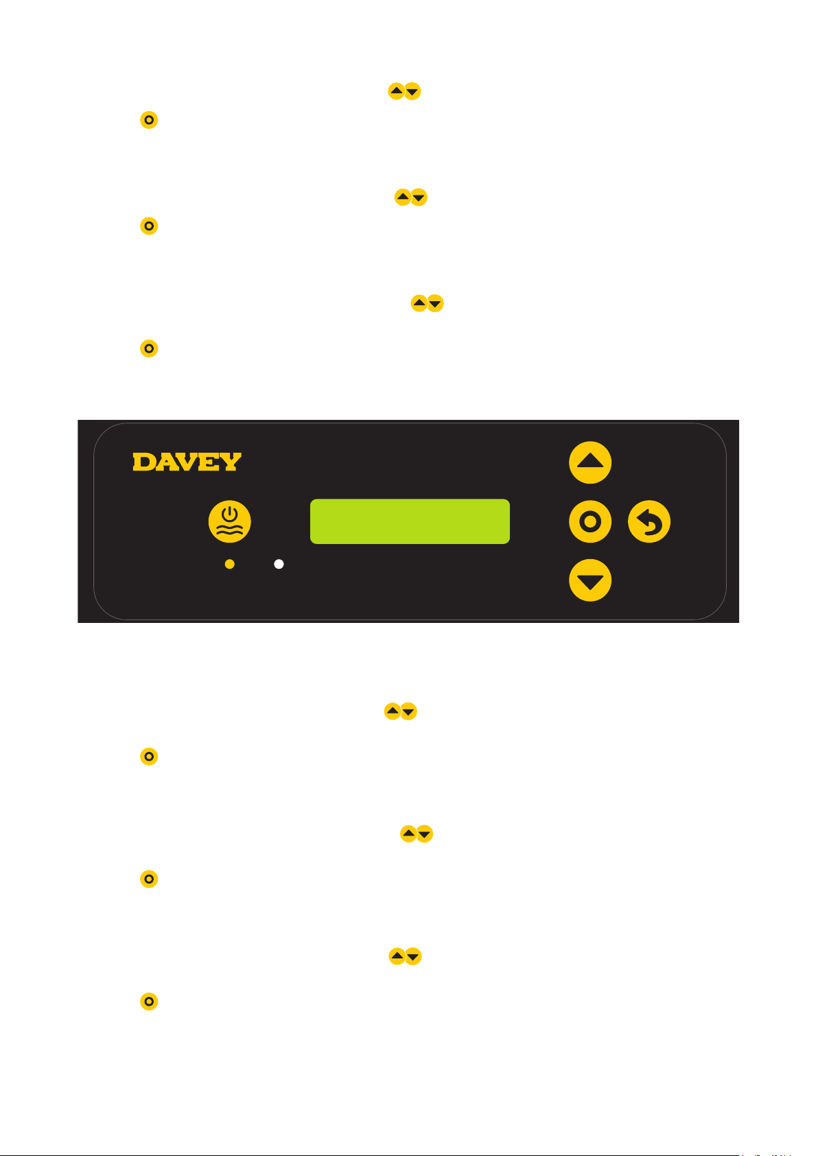
> From the HOME screen, press menu/setting select;
> The display will show this screen:
MODE
1. TIMER 1
Figure 12.11
> Using the menu up/down buttons scroll to the TIMER 2 menu.
MODE
2. TIMER 2
Figure 12.12
> From this screen, press menu/setting select to enter TIMER 2 menu;
> To adjust both the ON-TIME and OFF-TIME for TIMER 2, follow the same steps shown previously
for TIMER 1.
12.3 ACTIVATING COVER MODE
A pool’s exposure to UV contributes significantly to the pool’s total chlorine demand. Ie the amount of
chlorine the pool uses. Excessive amounts of chlorine in a pool with a cover on, can significantly shorten the
life expectancy of the pool cover, if left for long periods of time (eg weeks). Turning on the COVER MODE
reduces the cell duty cycle by 80% of its current setting.
For example:
• If the ChloroMatic Nipper is on for 8 hours per day, the CHLORINE OUTPUT is set to 50%, but the COVER
MODE is on: the ChloroMatic Nipper cell duty cycle is only 48 minutes, of that day;
20
Page 21

• If the ChloroMatic Nipper is on for 8 hours per day, the CHLORINE OUTPUT is set to 25%, but the COVER
MODE is on: the ChloroMatic Nipper cell duty cycle is only 24 minutes, of that day.
To turn on COVER MODE:
70% – 09:35 AM
CHLORINE OUTPUT
Figure 12.13
> From the HOME screen, press menu/setting select.
> The display will show this screen:
MODE
1. TIMER 1
Figure 12.14
> Use the menu up/down buttons to scroll to the COVER MODE menu:
MODE
3. COVER
Figure 12.15
> From this screen, press menu/setting select to enter COVER MODE menu;
> The display will show the current COVER MODE setting (ie COVER MODE off shown):
21
Page 22

3. COVER
OFF
Figure 12.16
> Press menu up/down buttons to toggle between COVER MODE on and off;
> Press
> This will then take you back to the first setting menu;
> If the ChloroMatic Nipper is left untouched for ~ 30 seconds, or the
button is pushed, the display reverts to the HOME screen.
menu/setting select once your preferred COVER MODE is displayed;
COVER MODE can also be triggered remotely
by an automated pool cover controller. By
closing the terminal block contacts on the rear
of the power supply, the ChloroMatic Nipper
will remotely switch to COVER MODE. This
can be overridden by user intervention, by
following the steps explained previously.
menu/setting cancel (go back)
Figure 12.17
22
Page 23

12.4 ACTIVATING BOOST MODE
Should the pool experience a heavy bather load, debris/contamination, or extreme warm weather, there may
be a need to super-chlorinate the pool. Turning on the BOOST MODE increases the cell duty cycle to 100%
and overrides the cell current (output) to 100% for a period of 24 hours.
To turn on BOOST MODE:
70% – 09:35 AM
CHLORINE OUTPUT
Figure 12.18
> From the HOME screen, press menu/setting select.
> The display will show this screen:
MODE
1. TIMER 1
Figure 12.19
> Press the menu up/down buttons to scroll to BOOST MODE;
MODE
4. BOOST
Figure 12.20
23
Page 24

> Press
menu/setting select;
4. BOOST
OFF
Figure 12.21
> The display will show the current BOOST MODE setting (ie BOOST MODE off shown);
> Press the
menu up/down buttons to toggle between BOOST MODE on and off;
4. BOOST
ON
Figure 12.22
> Press menu/setting select once your preferred BOOST MODE is displayed;
> This will then take you back to the first setting menu;
> If the Nipper is left untouched for ~ 30 seconds, or the
pushed, the display reverts to the HOME screen.
menu/setting cancel (go back) button is
50% – 09:40 AM
BOOST
Figure 12.23
> The HOME screen will continue to show the cell duty cycle percentage, however the reference to “ON” has
been notably replaced by the reference to “BOOST”. This will remain for the 24 hour period;
> It is possible to alter the cell duty cycle during a 24-hour boost and the display percentage on the HOME
screen changes as expected. This could be handy if the setting needs altering for the next day, once the
BOOST MODE is finished;
> It should be noted though, BOOST MODE overrides every other setting. During the 24 hour period while
is BOOST MODE is active, the cell current is 100% output, and duty cycle is overridden to 100%. This is
regardless of the display on the screen.
24
Page 25

12.5 ACTIVATING SPA MODE
The ChloroMatic Nipper system is compatible with large swimming pool applications as well as much smaller
spa applications. Turning on the SPA MODE reduces the cell duty cycle by 80% of its current setting.
For example:
• If the ChloroMatic Nipper is on for 10 hours per day, the CHLORINE OUTPUT is set to 50%, but the S PA
MODE is on: the ChloroMatic Nipper cell duty cycle is only 1 hour, of that day;
• If the ChloroMatic Nipper is on for 10 hours per day, the CHLORINE OUTPUT is set to 25%, but the spa
MODE is on: the ChloroMatic Nipper cell duty cycle is only 30 minutes, of that day.
To turn on SPA MODE:
70% – 09:35 AM
CHLORINE OUTPUT
Figure 12.24
> From the HOME screen, press menu/setting select.
> The display will show this screen:
MODE
1. TIMER 1
Figure 12.25
> Press the menu up/down buttons to scroll to SPA MODE;
MODE
5. SPA
Figure 12.26
> From this screen, press menu/setting select to enter SPA MODE menu;
> The display will show the current SPA MODE setting (ie SPA MODE off shown):
25
Page 26

5. SPA
OFF
Figure 12.27
> Press menu up/down buttons to toggle between SPA MODE on and off;
> Press
> This will then take you back to the first setting menu;
> If the ChloroMatic Nipper is left untouched for ~ 30 seconds, or the
button is pushed, the display reverts to the HOME screen.
12.6 ACTIVATING SPA MODE AND COVER MODE SIMULTANEOUSLY
Should it be necessary to run SPA MODE and COVER MODE simultaneously, the cell duty cycle is only
reduced by 80% That is, the cell duty cycle isn’t reduced by 80%, followed by a further 80%. The HOME
screen display will toggle between showing COVER and SPA.
12.7 ACTIVATING WINTER MODE
A pool’s exposure to UV contributes significantly to the pool’s total chlorine demand. Ie the amount of
chlorine the pool uses. Bather load is also a significant contributor to the pool’s total chlorine demand. In
winter, the pool’s chlorine demand is typically far less. Unless otherwise altered, if the cell is producing
chlorine, it is producing at 100% current (output). WINTER MODE reduces the cell’s current (output) to 85%.
For example:
• If the ChloroMatic Nipper is on for 10 hours per day, the CHLORINE OUTPUT is set to 100%, the WINTER MODE
is off: the ChloroMatic Nipper cell duty cycle is 10 hours. The cell current will be operating at 100% capacity;
• If the ChloroMatic Nipper is on for 10 hours per day, the CHLORINE OUTPUT is set to 100%, but the
WINTER MODE is on: while the ChloroMatic Nipper cell duty cycle is still 10 hours, the cell current will only
be operating at 85% capacity.
To turn on WINTER MODE:
menu/setting select once your preferred SPA MODE is displayed;
menu/setting cancel (go back)
70% – 09:35 AM
CHLORINE OUTPUT
Figure 12.28
> From the HOME screen, press menu/setting select.
> The display will show this screen:
26
Page 27

MODE
1. TIMER 1
Figure 12.29
> Press the menu up/down buttons to scroll to WINTER MODE;
MODE
6. WINTER
Figure 12.30
> From this screen, press menu/setting select to enter WINTER MODE menu;
> The display will show the current WINTER MODE setting (ie WINTER MODE off shown):
6. WINTER
OFF
Figure 12.31
> Press menu up/down buttons to toggle between WINTER MODE on and off;
> Press
> This will then take you back to the first setting menu;
> If the ChloroMatic Nipper is left untouched for ~ 30 seconds, or the
button is pushed, the display reverts to the HOME screen.
menu/setting select once your preferred WINTER MODE is displayed;
menu/setting cancel (go back)
27
Page 28

12.8 LOW FLOW ALARM
Should the ChloroMatic Nipper flow switch register a flow rate below 3.6m3/h (60L/min), the ChloroMatic
Nipper will enter LOW FLOW ALARM:
ALARM
LOW FLOW
Figure 12.32
In LOW FLOW ALARM, the ChloroMatic Nipper will not produce chlorine. Once the flow switch registers flow
above 3.6m3/h (60L/min), the ChloroMatic Nipper will return to normal operation. To achieve best efficiency,
the ChloroMatic Nipper cell should be installed such that turbulent water is limited as much as possible.
Do not install a 90° elbow closer that 200mm from the cell’s inlet barrel union. Isolation valves used where
equipment is located below pool water level, should also be installed no closer than 200mm from inlet barrel
union. This will assist laminar flow.
12.9 ADD SALT ALARM
Should the ChloroMatic Nipper register low conductivity within the cell, this could be triggered by cold water
(below 15ºC), or a salt concentration below its minimum (refer to recommended salt range section in the
manual), the ChloroMatic Nipper will enter ADD SALT ALARM. Additional salt may be added to overcome
a lower temperature. However, the maximum salt level should also be considered and if water temperature
drops too far, the system should be turned off.
ALARM
ADD SALT
Figure 12.33
Once the ChloroMatic Nipper registers a salt concentration within range (refer to recommended salt range
section in the manual), the ChloroMatic Nipper will return to normal operation.
12.10 LOW SALT CUT-OUT ALARM
Should the salt concentration continue to be diluted, the ChloroMatic Nipper will enter
LOW SALT CUT-OUT ALARM.
28
Page 29

ALARM
LOW SALT CUT-OUT
Figure 12.34
Once the salt concentration is corrected, the LOW SALT CUT-OUT ALARM must be reset by pushing the
manual ON/OFF button. Alternatively, the ChloroMatic Nipper will conduct a system check automatically
when powered up the next time (if operating via a separate power supply). Upon start-up if the ChloroMatic
Nipper registers a salt concentration within range (refer to recommended salt range section in the manual),
the ChloroMatic Nipper will return to normal operation.
LOW SALT CUT-OUT ALARM is triggered at the following (approximate) salt concentrations:
ChloroMatic Nipper model Low salt cut-out alarm (approx. salt concentration)
DNP15CLS, DNP25CLS 1,200ppm
DNP15C, DNP25C, DNP35C 2,500ppm
12.11 ADD SALT ALARM AND LOW FLOW ALARM
Should the ChloroMatic Nipper register low flow and a salt concentration below its minimum (refer to
recommended salt range section in the manual), the ChloroMatic Nipper will alarm. The display will toggle
between the ADD SALT ALARM and the LOW FLOW ALARM. In LOW FLOW ALARM, the ChloroMatic
Nipper will not produce chlorine. As shown previously once faults are rectified, normal operation will resume.
12.12 OVERRIDING CLOCK SETTING
70% – 09:35 AM
CHLORINE OUTPUT
Figure 12.35
> From the HOME screen, press and hold menu/setting select for 3 seconds.
29
Page 30

Figure 12.36
> Press menu/setting select;
> The display will show this screen.
Figure 12.37
SETTINGS
1. CLOCK
1. CLOCK
1 1:21 AM
> This screen shows the clock’s current time (ie 11:21AM shown);
> Initially the clock hours will be flashing;
> The clock hours can be changed by pressing the
> Press
> If a mistake is made, the setting can be changed later;
> Next, the clock minutes will be flashing;
> The clock minutes can be changed by pressing the
chosed time;
> Press
> If a mistake is made, the setting can be changed later;
> Next, the clock AM/PM will be flashing;
> The clock AM/PM can be changed by pressing the
between AM and PM;
> Press
> If a mistake is made, the setting can be changed later;
> If the ChloroMatic Nipper is left untouched for ~ 30 seconds, or the
button is pushed, the display reverts to the HOME screen.
menu/setting select once your preferred clock hour is displayed;
menu/setting select once your preferred clock minutes is displayed;
menu/setting select once your preferred clock AM/PM is displayed;
menu up/down buttons to scroll to your chosen time;
menu up/down buttons to scroll to your
menu up/down buttons to toggle
menu/setting cancel (go back)
30
Page 31

12.13 OVERRIDING DATE SETTING
70% – 09:35 AM
CHLORINE OUTPUT
Figure 12.38
> From the HOME screen, press and hold menu/setting select for 3 seconds.
SETTINGS
1. CLOCK
Figure 12.39
> Press the menu up/down buttons to scroll down to DATE menu;
SETTINGS
2. DATE
Figure 12.40
> Press menu/setting select;
2. DATE
27 FEB 2019
Figure 12.41
31
Page 32

> This screen shows the date format menu and the current date (ie 27 FEB 2019 sown);
> Initially the date day will be flashing;
> The date day can be changed by pressing the
chosen date day;
> Press
> If a mistake is made, the setting can be changed later.
> Next the date month will be flashing;
> The date month can be changed by pressing the
date month;
> Press
> If a mistake is made, the setting can be changed later.
> Next the date year will be flashing;
> The date year can be changed by pressing the
date year;
> Press
> If the ChloroMatic Nipper is left untouched for ~ 30 seconds, or the
button is pushed, the display reverts to the HOME screen.
12.14 OVERRIDING LANGUAGE SETTING
menu/setting select once your preferred date day is displayed;
menu/setting select once your preferred date month is displayed;
menu/setting select once your preferred date year is displayed;
menu up/down buttons to scroll to your
menu up/down buttons to scroll to your chosen
menu up/down buttons to scroll to your chosen
menu/setting cancel (go back)
70% – 09:35 AM
CHLORINE OUTPUT
Figure 12.42
> From the HOME screen, press and hold menu/setting select for 3 seconds.
SETTINGS
1. CLOCK
Figure 12.43
> Press the menu up/down buttons to scroll down to LANGUAGE menu;
32
Page 33

SETTINGS
3. LANGUAGE
Figure 12.44
> Press menu/setting select;
> The current LANGUAGE chosen will flash;
> Use the
Figure 12.45
> Press menu/setting select once your preferred LANGUAGE is displayed;
> If the ChloroMatic Nipper is left untouched for ~ 30 seconds, or the
button is pushed, the display reverts to the HOME screen.
12.15 OVERRIDING TIME FORMAT SETTING
menu up/down buttons to scroll to your preferred LANGUAGE;
3. LANGUAGE
3. LANGUAGE
ENGLISH
ENGLISH
menu/setting cancel (go back)
70% – 09:35 AM
CHLORINE OUTPUT
Figure 12.46
> From the HOME screen, press and hold menu/setting select for 3 seconds.
33
Page 34

SETTINGS
1. CLOCK
Figure 12.47
> Press the menu up/down buttons to scroll down to TIME FORMAT menu;
SETTINGS
4. TIME FORMAT
Figure 12.48
> Press menu/setting select;
> The current TIME FORMAT chosen will flash;
> Use the
> Press
> If the ChloroMatic Nipper is left untouched for ~ 30 seconds, or the
button is pushed, the display reverts to the HOME screen.
12.16 DISPLAY ALARM HISTORY
The ChloroMatic Nipper keeps a history log for the user that registers the number of hours during which the
ChloroMatic Nipper is in alarm mode. As a reminder, the cell life expectancy will be reduced if the ChloroMatic
Nipper is run with salt concentrations outside of the recommended range.
menu up/down buttons to scroll to your preferred TIME FORMAT, either 12HR, or 24HR;
menu/setting select once your preferred TIME FORMAT is displayed;
menu/setting cancel (go back)
70% – 09:35 AM
CHLORINE OUTPUT
Figure 12.49
34
Page 35

> From the HOME screen, press and hold
menu/setting select for 3 seconds.
SETTINGS
1. CLOCK
Figure 12.50
> Press the menu up/down buttons to scroll down to ALARM HISTORY menu;
SETTINGS
5. ALARM HISTORY
Figure 12.51
> Press menu/setting select;
CELL RUN TIME
0
Figure 12.52
> Press the menu up/down buttons to toggle between cell run time and low salt time.
LOW SALT TIME
0
Figure 12.53
35
Page 36

13. MAINTENANCE OF POWER SUPPLY
Little, or no maintenance is typically required. However, it is essential that the wall or post to which the
ChloroMatic Nipper is installed be sprayed (not the ChloroMatic Nipper itself) periodically with a good surface
type insect repellent, since penetration by insects may cause damage, which is not covered by your warranty.
IMPORTANT. Certain local electrical regulations state “If the supply cord is damaged, it
must be replaced by a special cord available from the manufacturer or its service agent”.
14. MAINTENANCE OF THE ELECTROLYTIC CELL
The ChloroMatic Nipper cell is composed of precious materials, and although proper maintenance can
prolong its life to the maximum, eventually the output will wear away its delicate coating, at which time it
gradually ceases to produce chlorine. Calcium (scale) is deposited on the plates as electrolysis takes place.
This build up will interfere with the flow of electrical current in the cell and thus lowers chlorine production. It
is essential to inspect the cell regularly and clean when necessary. The rate at which deposits will form on
the plate differs with each pool and can be influenced by the following:
• Calcium Hardness of the water;
• Water temperature;
• pH level;
• Water which has been chlorinated with calcium hypochlorite for an extended period; and/or
• Calcium in the plaster surfaces of a concrete pool.
Because these conditions vary so much, check the cell at least weekly to begin with to see if either scale
or a blue/green soapy substance appears on the plates. You will then be able to determine the cleaning
cycle necessary for your pool (more frequent cleaning may be required in summer). The intervals between
cleaning could get longer to the point where cleaning is only necessary a couple of times each year.
NOTE: In areas with hard water, even reverse polarity systems may require occasional
manual cleaning.
The life of the ChloroMatic Nipper cell varies substantially from one installation to another due to variations in
operating time, water quality and composition, system and cell maintenance.
Please ensure that when cell replacement is necessary you use the correct genuine ChloroMatic Nipper
replacement cell to match your system. The correct ChloroMatic Nipper replacement cells to use are shown
in the table below:
Model Replacement Cell Code
DNP15C DES2C15REPAU
DNP15CLS DES2C25REPAU
DNP25C DES2C25REPAU
DNP25CLS DES2C35REPAU
DNP35C DES2C35REPAU
ALWAYS INSIST ON GENUINE DAVEY REPLACEMENT PARTS.
If it is necessary to replace the electrolytic cell, beware of
“look-a-likes”. Only the Genuine ChloroMatic Nipper cell
is designed and warranted to operate with the ChloroMatic
Nipper Power Supply.
SERIOUS DAMAGE MAY RESULT TO THE ELECTRONICS
INSIDE THE ChloroMatic Nipper, IF CLONE CELLS ARE USED.
THIS MAY ALSO VOID WARRANTY.
14.1 TO CLEAN THE ChloroMatic Nipper CELL
Ensure that the ChloroMatic Nipper and pool pump is turned off. Failure to do so may result in the pool
pump turning on while the cell is not in place. Disconnect the flow switch and cell lead from the top of the cell
housing. Remove the cell from the pool return line by undoing the cell nut, taking care not to lose the o-rings.
36
Page 37

Method one:
Add 1 part HYDROCHLORIC ACID to 10 parts WATER in a suitable container and immerse the cell in this
solution. It should not take longer than a few minutes to clean, if it does the cell should be cleaned more
frequently. If the build – up is not excessive it may be possible to clean the cell plates with a jet of running
water. Return the cell to its housing and connect leads to the head assembly.
Method two:
As an alternative, an approved commercial cell cleaning solution can be used a number of times effectively.
NOTE: Always add acid to water. Never add water, to acid. Always wear eye protection
and rubber gloves. Always clean the cell in a well-ventilated area.
14.2 RE-INSTALLING CELL AFTER CLEANING OR REPLACEMENT
When re-installing the ChloroMatic Nipper cell into the housing, ensure that the cell locking nut is tight. Do
this by turning on the pool pump once fitted, then checking for leaks.
If there is a leak, remove the lock nut and inspect the o-ring for debris, or damage. Then re-try. Before refitting the cell connectors, ensure that the terminals are dry.
14.3 SAFETY DEVICE
Hydrogen Gas is a by-product of the chlorine producing process. A Flow Switch has been supplied with the
ChloroMatic Nipper, which will stop output if low or no flow is detected. The ChloroMatic Nipper system will
run to flows down to 3.6m³/h (60L/min).
15. DAY TO DAY OPERATION
Four prime rules must be observed if your unit is to give the best possible service:
15.1 STABILISER
The importance of pool stabiliser cannot be over – emphasised. It is essential in helping retain chlorine
in your pool. Chlorine is rapidly dissipated by sunlight and the use of stabiliser will reduce this dissipation
substantially. Without stabiliser, it may be necessary to run the Unit for up to three times as long!
Stabiliser should be added at the rate of 500 grams for every 10,000 litres of water. Stabiliser should be
maintained at a level of 25-50ppm. If a ORP controller is used, Stabiliser should be maintained at a level of
15-25ppm. Before adding more stabiliser, have your pool water analysed at your pool shop to ensure that
you do not add too much. (FOR OUTDOOR POOLS ONLY, INDOOR DO NOT REQUIRE STABILISER).
37
Page 38

15.2 pH AND TOTAL ALKALINITY
A correct pH level must be maintained to prevent problems such as black spot, staining, cloudy water, etc.
An incorrect pH level can damage the pool. Correct pH levels are as follows; Fibreglass – 7.2 to 7.4;
Concrete & tiled – 7.4 to 7.6 If you allow the pH level to rise to 8.0 or above, the chlorine required could be
as much as three times the normal amount, in order to correctly sanitise the pool.
Total Alkalinity should not be confused with pH. Although the two are closely related, Total Alkalinity determines
the speed and ease of pH change. The ideal range is 80 – 150 ppm or, refer to your pool professional.
You should use a test kit which includes a test for Total Alkalinity. Low Total Alkalinity can cause unstable pH
levels. An inability to keep the pH constant may cause staining, etching and corrosion of metals. High Total
Alkalinity will cause constantly high pH levels and tends to encourage Calcium scaling.
15.3 TDS LEVELS
WARNING: Some people recommend that you put salt directly in the skimmer box.
This is a poor practice as it allows very high concentrations of salt to be passed
through your ltration and other pool equipment.
Salt is the essential element by which your ChloroMatic Nipper operates with. Insufficient Salt will damage your cell.
RECOMMENDED SALT LEVEL RANGE
Nipper model Operating salt level Add salt alarm
DNP15CLS, DNP25CLS 1,500 – 6,000ppm ~ 1,500ppm
DNP15C, DNP25C, DNP35C 3,000 – 6,000ppm ~ 3,000ppm
WARNING: Do not add Hydrogen Peroxide to pool water or through swimming pool hydraulic,
or sanitiser system. Use of Hydrogen Peroxide will void warranty on Davey products.
Salt is NOT used up in the chlorination process, or by evaporation. It is only lost through dilution caused
from: backwashing, splash-out, overflow, leakage from the pool, or plumbing. Heavy rain can dilute the salt
levels in your pool therefore, salt levels should be checked during these events.
Low salt levels will destroy the coating on the cell plates and will void all Warranty.
The ChloroMatic Nipper has a built-in warning indicator to minimise damage resulting from insufficient salt
levels however, the ultimate responsibility is on the owner to ensure adequate salt levels are maintained all
year round.
15.4. RUNNING TIMES
These instructions cover Nipper for residential use only.
If you run your Sanitiser on maximum output for, 24 hours a day, or for longer periods, the cell life will be
greatly reduced. It is important that the correct model ChloroMatic Nipper has been installed on your pool.
Many models are available from Davey to cope with small courtyard pools up to commercial size pools.
(Consult your local Nipper Dealer for more information).
Note: The ChloroMatic Nipper warranty does not apply to commercial or semi-commercial applications,
i.e. where the pool chlorine demand is far in excess of a typical residential pool.
38
Page 39

16. CHLORINE PRODUCTION
The ChloroMatic Nipper must be run daily to generate sufficient chlorine to sanitise the pool. During summer a
typical installation would require eight hours per day of chlorination. Depending on when you choose to run the
ChloroMatic Nipper, it is best to test the residual Chlorine in the pool at the point where you would anticipate
the levels be at their lowest. At that chosen time of the day, if the residual Chlorine level from your test is
reading too high, reduce the ChloroMatic Nipper CHLORINE OUTPUT. Alternatively, if the residual Chlorine
level from your test is reading too low, increase the ChloroMatic Nipper CHLORINE OUTPUT (refer to page
16). Correct chemical balances (see page 39) are critical to ensure the ChloroMatic Nipper performs correctly.
In cooler times of the year, it’s typically possible to reduce running hours of the ChloroMatic Nipper. Follow
instruction from your pool professional. Chlorine output can also be reduced throughout this time by entering
WINTER MODE, (see page 26).
16.1 “SHOCK” TREATMENT
Periodically, especially during extremely hot conditions, it may be necessary to boost the chlorine level in the
pool. This can be achieved by selecting BOOST MODE, which will run the system on full for 24 hours, (see
page 22). Alternatively, add either liquid, or granulated chlorine. If granulated chlorine is added, the cell must
be checked regularly, since the additives from this product can clog the electrodes.
16.2 CHLORINE TYPES AND COMPARISONS / MAX POOL SIZE
Many chlorinator manufacturers calibrate their units to compare with 65% granulated chlorine, making it
necessary to adjust their readings to a lower level in order to determine true chlorine production. Below is a
comparison table of the available types of chlorine used to sanitise pools.
ChloroMatic
Nipper
Model
Production
Maximum
(g/hr 100%)
Production
(g/hr 65%
equivalent)
Chlorine
produced
over 8 hours
(grams 100%)
Cool Climates
<25ºC
DNP15C(LS) 15 23 120 75m
Maximum Pool Size
Temperate
Climates
25ºC to 30ºC
3
58m
DNP25C(LS) 25 38 200 125m3 96m
DNP35C 35 53 280 175m3 134m
NOTE: The appropriate ChloroMatic Nipper for your pool is dependent on the local
climate, bather load of the pool and running times. Please note that the ChloroMatic
Nipper cell life can be increased with shorter running times during winter and lower
output settings. Davey recommends the ChloroMatic Nipper be run for between 6 - 8
hours a day during summer, and 4 hours during winter.
Hot & Tropical
Climates
>30ºC
3
3
3
46m
80m
112m
3
3
3
39
Page 40

17. GENERAL INFORMATION
17.1 POOL WATER CHEMISTRY INSTRUCTIONS
POOL
WATER
BALANCE
Ideal
reading
/ range
To increase
To decrease
Free Chlorine
(ppm)
1.5 - 3
Increase
output of
sanitiser.
Add chlorine.
Increase
ltrationtime.
Decrease
output of
sanitiser.
Decrease
ltrationtime.
pH
Concrete &
tiled pools
7.4-7.6
Other surfaces
7.2-7.4
Add Soda
Ash (Sodium
Carbonate)
Add
Hydrochloric
Acid
Total
Alkalinity TA
(ppm)
80 - 150
Add Buffer
(Sodium
Bicarbonate)
Add
Hydrochloric
Acid or Dry
Acid
Calcium
Hardness
(ppm)
Concrete &
tiled pools
200-275
Other surfaces
100-225
Add Calcium
Chloride
Partially drain
&rellpool
with lower
hardness
water to Dilute
Stabiliser -
Cyanuric Acid
(ppm)
25-50ppm
(15-25ppm if
used with an
ORP controller)
Not to be used
in indoor pools.
Add Cyanuric
Acid
Partially drain
&rellpoolto
dilute
Recommended
salt Levels
(ppm)
Depends on
model (see
page 38)
Add salt
Partially drain
&rellpoolto
dilute
Frequency
of testing
Weekly Weekly Weekly Weekly Regularly Regularly
18. TROUBLE SHOOTING
No Chlorine Production - Check for:
1. No power to system
2. Insufficient flow from pump
3. Control set to manual off
4. CHLORINE OUTPUT set to “0” setting
5. Dirty cell
6. Filter needs back washing
7. Flow switch not connected or damaged
8. Salt level too low triggering low salt cut-out
9. Main house fuse blown
10. Pump faulty
Low Chlorine Production - Check for:
1. Dirty cell - clean if required
2. Filter needs back washing
3. Pool stabiliser too low
4. pH too high
5. Salt level too low
6. Running time inadequate
7. CHLORINE OUTPUT set too low
8. POOL COVER MODE accidently turned on
9. SPA COVER MODE accidently turned on
10. WINTER MODE accidently turned on
11. Pump faulty
12. Cell failing
40
Page 41

18. SPARE PARTS
18.1 SPARE PARTS EXPLODED DIAGRAM
ChloroMatic Nipper Chlorinator
ChloroMatic Nipper Chlorinator Low Salt
3
12
6
2
4
1
18
5 5
15
16
17
DNP15C DNP25C DNP35C
DNP15CLS DNP25CLS
7
7
9
8
10
11
13
14
19
QTY
ITEM NOTES DESCRIPTION
1 Cell Connection Plug Assy 1 33021
2 Cell Locking Ring 1 16058
3 O-ring - Cell Head 1 403377
4 Paddle Switch 1 16102-1
5 Barrel Union Assembly 2 48722B
6 Cell Body 1 16056
7 Screw 12 403625
8 Switch mode power supply DNP15C (LS) 1 403368
8 Switch mode power supply DNP25C (LS) & DNP35C 1 403369
9 Pump Loom 1 16075
10 Mains Loom 1 16073
11 Power Cord 240v 1 403370
12 Replacement Cell DNP15C 1 DES2C15REPAU
12 Replacement Cell DNP25C, DNP15CLS 1 DES2C25REPAU
12 Replacement Cell DNP35C, DNP25CLS 1 DES2C35REPAU
13 Bush Power Cable 1 403372
14 PCB DNP15C 1 33005C-15ASP
14 PCB DNP15CLS 1 33005C-15ALSP
14 PCB DNP25C 1 33005C-25ASP
14 PCB DNP25CLS 1 33005C-25ALSP
14 PCB DNP35C 1 33005C-35ASP
15 PCB LCD 1 16046
16 PCB LCD Gasket 1 16077
17 Screw LCD 4 403366
18 Control Panel Decal 1 16047
19 Front Casing 1 16042
REQ’D PART NO.
41
Page 42

NOTES
42
Page 43

43
Page 44

DAVEY WARRANTY
Davey Water Products come with guarantees that cannot be excluded under the local country Law. You are
entitled to a replacement, or refund for a major failure and compensation for any other reasonably foreseeable
loss, or damage. You are also entitled to have the goods repaired or replaced if the goods fail to be of acceptable
quality and the failure does not amount to a major failure.
Davey Water Products Pty Ltd (Davey) of 6 Lakeview Drive Scoresby VIC 3179 provides the following warranty in
relation this product. Davey warrants that, subject to the exclusions and limitations below, the product will be free
from defects in material and workmanship for a period of 36 months from the date of purchase (warranty period).
If a defect appears in the product before the end of the warranty period and Davey finds the product to be
defective in materials or workmanship, Davey will, in its sole discretion, either:
1. replace or repair the product or the defective part of the product free of charge; or
2. arrange for the product or the defective part of the product to be repaired or replaced by a qualified repairer
free of charge.
Davey reserves the right to replace defective parts of the product with parts or components of similar quality,
grade and composition where an identical part or component is not available. Goods presented for repair may be
replaced by refurbished goods of the same type rather than being repaired.
Warranty claims:
1. If a fault covered by the warranty occurs, Davey suggests, in the first instance, that you contact the Davey
Dealer from whom you purchased the product. Alternatively contact Davey at the below mentioned offices.
2. Any warranty claim must be accompanied by proof of purchase and details of the alleged defect.
3. On receipt of your claim, Davey will seek to resolve your difficulties, or if the product is faulty or defective,
advise you on how to have your product repaired, obtain a replacement or a refund.
4. This warranty is limited to defects in the materials or workmanship in the product and does not cover
expendable parts or the replacement of parts due to fair wear and tear.
Exclusions:
The warranty will not apply where:
The Product has been modified, repaired or serviced by someone other than Davey, or an authorised repairer.
1.
2. Davey cannot establish any fault in the product after testing.
3. The product has been used other than for the purpose for which it was designed.
4. The product has been subject to abnormal conditions, whether of temperature, water, humidity, pressure,
stress or similar.
5. The purchaser has used or fitted non-genuine, or non-approved parts and accessories.
6. The Product defect has arisen due to abuse, misuse, neglect or accident.
7. The Product defect has arisen due to the purchaser’s failure to properly maintain or use the product.
8. The damage has been caused by the use of chemicals and detergents not approved by Davey.
Should your Davey product require repair or service after the warranty period, please contact your nearest
Davey Dealer, or phone or email the Davey Customer Service Centre. For a complete list of Davey Dealers
please visit our website.
NEW ZEALAND
7 Rockridge Avenue,
Penrose, Auckland 1061
Ph: 0800 654 333
Fax: 0800 654 334
Davey Water Products Pty Ltd
Member of the GUD Group
ABN 18 066 327 517
AUSTRALIA
Head Offi ce
6 Lakeview Drive,
Scoresby, Australia 3179
Ph: +613 9730 9124
Fax: +613 9753 4248
Email: export@davey.com.au
Website: davey.com.au
® Davey is a trademark of Davey Water Products Pty Ltd. © Davey Water Products Pty Ltd 2019.
Email: sales@dwp.co.nz
Website: daveynz.co.nz
EUROPE
ZAC des Gaulnes
355 Avenue Henri Schneider
69330 Meyzieu, France
Ph: +33 (0) 4 72 13 95 07
Fax: +33 (0) 4 72 33 64 57
Email: info@daveyeurope.eu
Website: daveyeurope.eu
NORTH AMERICA
Ph: 1-877-885-0585
Email: info@daveyusa.com
Website: daveyusa.com
MIDDLE EAST
Ph: +971 50 6368764
Fax: +971 6 5730472
Email: info@daveyuae.com
Website: daveyuae.com
P/N 403603-2
 Loading...