

Page 1

INSTALLATION AND
OPERATING INSTRUCTIONS
CF Series
ISO2858 Heavy Duty
Industrial Centrifugal Pump
Please pass these instructions on to the operator of this equipment.
Page 2
Introduction
Thank you for purchasing a quality Davey product. It
is our commitment to satisfy our customers by offering
our very best service.
This manual contains instruction for installation,
operation and maintenance of ISOspec® CF
bareshaft, single stage, non-self priming, centrifugal
pumps. Therefore, please read it carefully before use
to obtain a long satisfying service life of the purchased
unit.
Davey ISOspec® CF bareshaft centrifugal pumps are
designed with high efciency and low maintenance
features.
Specications
Model designation (example) :-
CF 200×150-500
Nominal dia. of impeller (mm)
Dia. of outlet (mm)
Dia. of inlet (mm)
Series code of pump
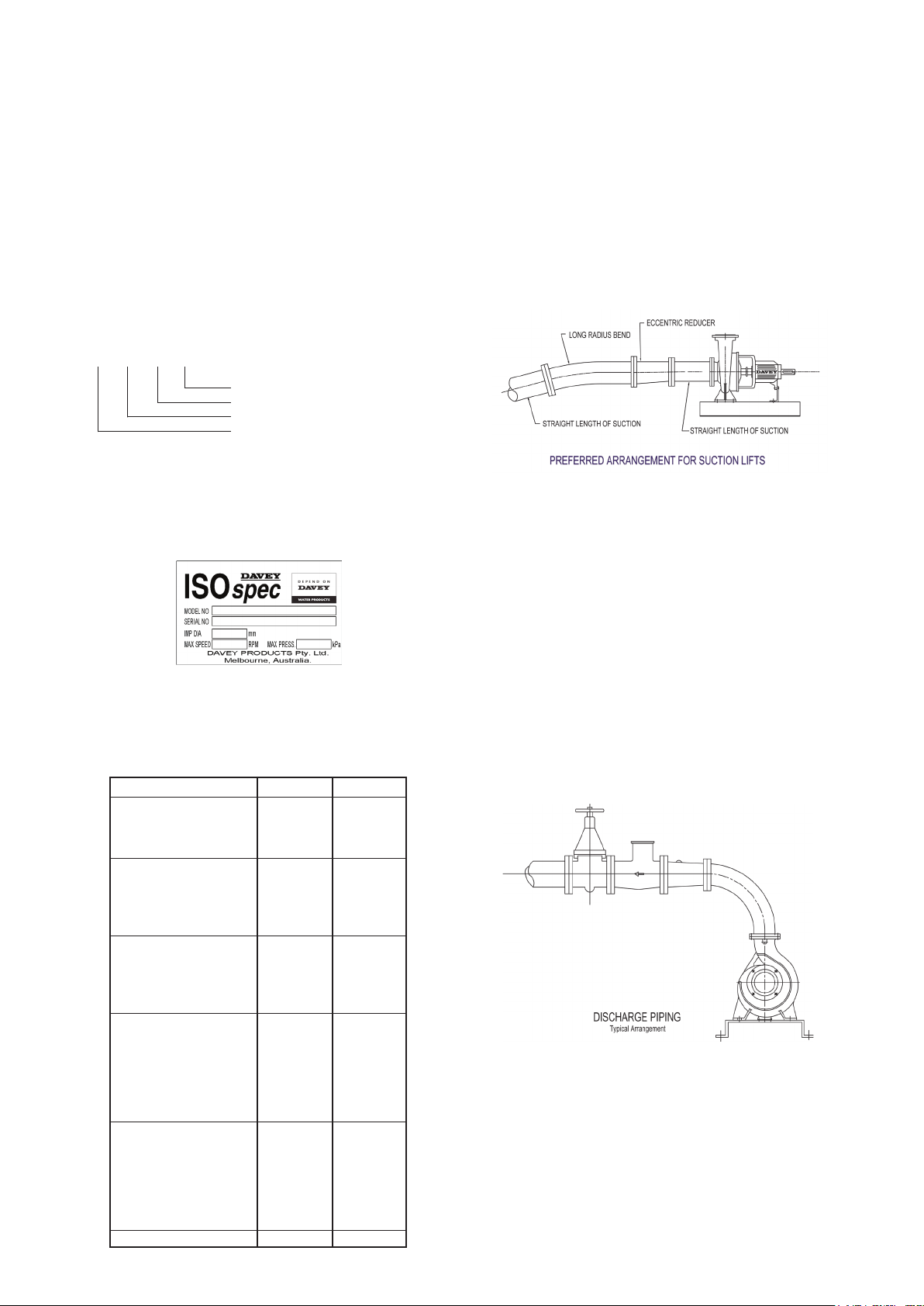
Inspection of Pump
Always check on receipt of delivery you have
received the correct pump unit. To identify, see above
specications and label below. Check correct motor
kW & speed on motor nameplate (attached to motor)
prior to installation.
Installation Location
It is important to select a site as close to the
liquid source as possible. When a suction lift is
unavoidable, install the pump as near to the water
level as possible (see suction piping). You should
always check the maximum permissible lift of the
pump from its performance curve.
Foundations
The pump unit should be mounted on a foundation
that is substantial enough to withstand the weight of
the unit & large enough to accommodate all mounting
feet so they can be securely xed to avoid movement.
Suction Piping
All ttings & suction piping should be free of air leaks.
When a suction lift or long suction lengths are
unavoidable, consideration should be given to over
sizing the suction line to reduce suction losses. On
suction lifts a foot valve will be required, sized equal to
the suction line size. For applications on creek beds
or dams, please install a foot valve & strainer, well
submerged below the surface, to reduce whirlpools
& air inclusion. Air inclusion can result in cavitation
reducing the pump performance & eventually
destroying the pump or its components.
Driving Options
Your ISOspec® pump can be driven by a variety of
means. The best option is to direct drive via a suitable
coupling. If you must belt drive your ISOspec® pump,
lower speed (rpm). Limits may apply - see below:
Pump Size Direct Belt
50x32-160 3600 2900
65x50-160 3600 2900
80x65-160 3600 2900
100x80-160 3600 2850
50x32-200 3600 2900
65x40-200 3600 2900
80x50-200 3600 2900
100x65-200 3600 2250
125x100-200 3600 2060
65x40-250 3600 2480
80x50-250 3600 2050
100x65-250 3600 2180
125x100-250 3000 1620
150x125-250 2350 1440
65x40-315 3000 1800
80x50-315 3000 1800
100x65-315 3000 1450
125x100-315 3000 1380
150x125-315 2350 1420
200x150-315 1800 1150
250x200-315 1800 920
125x80-400 2350 1450
125x100-400 2350 1240
150x125-400 2350 1060
200x150-400 1800 920
125x100-500 1800 1240
150x125-500 1800 1060
200x150-500 1800 920
250x200-400 1800 920
Long radius bends should be installed & a straight
length of piping equal to 2.5, the impeller diameter,
should be observed. Supporters should be equipped
to the inlet pipeline and outlet pipeline to avoid the
pump ange bearing too much tension force.
Discharge Piping
Discharge piping must be selected of a size that
would equal the discharge of the pump. For long
discharge lengths, consideration should be given to
oversize to minimize discharge losses reducing ow.
Talk to your nearest Davey dealer to calculate all
system losses. To avoid air pockets in discharge
lines at high points, vent cocks may be required to
release air blocks accumulated within the system. Air
pockets may affect the performance of the pump. A
throttling valve should be installed in the discharge
line to ensure the pump works within the performance
curve.
~ 2 ~
Page 3

Starting
Caution: Do not attempt to run pump if it
has not been lled with water ( primed).
Severe damage will result to shaft seal.
1) Ensure the suction line & pump casing is full of water
open suction valve if tted.
2) Check power is off & rotate the pump shaft slowly to
release any trapped air within the pump casing.
3) Close the discharge valve.
4) Check the direction of rotation on the pump casing or
motor cover.
5) If this is correct you may now start the pump, when
it reaches full speed you will see the pressure in the
discharge line rise. Slowly open the discharge valve
until the pump adjusts to maintain its duty point.
Trouble Shooting
Pump is running but failing to deliver water or
desired pressure.
1) Turn the unit off.
2) Check suction line is free of debris or blockages
& check that the pump has not lost its prime. If
so, remove blockage & repeat Starting at step 1).
3) Check that the suction valve is open.
4) Check that the discharge valve is open.
5) Check for air leaks. These may not always be
visible to the naked eye unless pressure is applied
to the suction line.
6) Check that the suction line is not too long.
7) Is suction line to pump excessive?
8) Is the foot valve stuck open or undersized?
9) Is speed too slow?
10) Check motor direction rotation.
11) Check for possible clogging in impeller vanes
12) Is the discharge piping undersized for
applications.
Structural Representation
1. Bearing housing 2. Shaft
3. Rear casing cover 4. Pump casing
5. Impeller 6. Impeller key
7. Impeller washer 8. Impeller nut
9. Volute drain plug 10. Bronze wear ring
11. Mechanical shaft seal 12. Bearing housing foot
13. Bearing lip seal 14. Bearing
15. Bearing cap 16. Water slinger
Excessive Vibration
1) Turn unit off
2) Check motor is rotating in correct direction
3) Check both motor feet & pump feet are secured
properly.
4) Check coupling rubbers are not worn
5) Check drive couplings are secured tightly to the
pump & drive shafts.
6) Check pump & motor bearings are OK
7) If so, alignment will need to be performed
8) Impeller could be partially blocked causing
imbalance
Noisy Operation
1) Turn unit off
2) Check pump or motor bearings
3) Check pump is primed
4) Check suction line is not damaged causing
insufcient supply & resulting in cavitation
5) Check you are not pumping solids
High Power Consumption
1) Check direction of rotation
2) Check operating speed on the motor matches the
intended performance curve speed.
3) Check that the estimated head is correct as pump
may be running down on its curve producing high
ow but drawing more power. Throttle the pump
back on to its curve via discharge gate valve or
reduce impeller diameter.
4) The Specic Gravity or Density of the liquid is
greater than 1kg/litre affecting power draw.
5) Check impeller diameter for the correct size to
establish maximum power requirement at duty
point.
In accordance with AS 3350.2.41 we are obliged
to inform you that this pump is not to be used by
children or inrm persons and must not be used
as a toy by children.
Lubrication
Pump bearings are greased for life.
Motor bearings refer to Motor manufacturers
recommendations.
~ 3 ~
Page 4

Davey® Repair or Replacement Guarantee
In the unlikely event in Australia or New Zealand that this Davey product develops any malfunction
within one year of the date of original purchase due to faulty materials or manufacture, Davey will at
our option repair or replace it for you free of charge, subject to the conditions below.
Should you experience any difculties with your Davey product, we suggest in the rst instance that
you contact the Davey Dealer from which you purchased the Davey product. Alternatively you can
phone our Customer Service line on 1300 367 866 in Australia, or 0800 654 333 in New Zealand, or
send a written letter to Davey at the address listed below. On receipt of your claim, Davey will seek to
resolve your difculties or, if the product is faulty or defective, advise you on how to have your Davey
product repaired, obtain a replacement or a refund.
Your Davey One Year Guarantee naturally does not cover normal wear or tear, replacement of product
consumables (i.e. mechanical seals, bearings or capacitors), loss or damage resulting from misuse
or negligent handling, improper use for which the product was not designed or advertised, failure to
properly follow the provided installation and operating instructions, failure to carry out maintenance,
corrosive or abrasive water or other liquid, lightning or high voltage spikes, or unauthorized persons
attempting repairs. Where applicable, your Davey product must only be connected to the voltage
shown on the nameplate.
Your Davey One Year Guarantee does not cover freight or any other costs incurred in making a claim.
Please retain your receipt as proof of purchase; you MUST provide evidence of the date of original
purchase when claiming under the Davey One Year Guarantee.
Davey shall not be liable for any loss of prots or any consequential, indirect or special loss, damage or
injury of any kind whatsoever arising directly or indirectly from Davey products. This limitation does not
apply to any liability of Davey for failure to comply with a consumer guarantee applicable to your Davey
product under the Australian or New Zealand legislation and does not affect any rights or remedies that
may be available to you under the Australian or New Zealand Consumer Legislation.
In Australia, you are entitled to a replacement or refund for a major failure and for compensation for
any other reasonably foreseeable loss or damage. You are also entitled to have the goods repaired or
replaced if the goods fail to be of acceptable quality and the failure does not amount to a major failure.
Should your Davey product require repair or service after the guarantee period; contact your nearest
Davey Dealer or phone the Davey Customer Service Centre on the number listed below.
For a complete list of Davey Dealers visit our website (davey.com.au) or call:
AUSTRALIA
Customer Service Centre
6 Lakeview Drive,
Scoresby, Australia 3179
Ph: 1300 367 866
Fax: 1300 369 119
Website: davey.com.au
NEW ZEALAND
Customer Service Centre
7 Rockridge Avenue,
Penrose, Auckland 1061
Ph: 0800 654 333
Fax: 09 527 7654
Website: daveynz.co.nz
Davey Water Products Pty Ltd
Member of the GUD Group
ABN 18 066 327 517
® Davey & ISOspec are registered trade marks of Davey Water Products Pty Ltd.
© Davey Water Products Pty Ltd 2011.
* Installation and operating instructions are included with the product when purchased new.
They may also be found on our website.
P/N 49719-4 supersedes P/N 49719-3
 Loading...