

Page 1
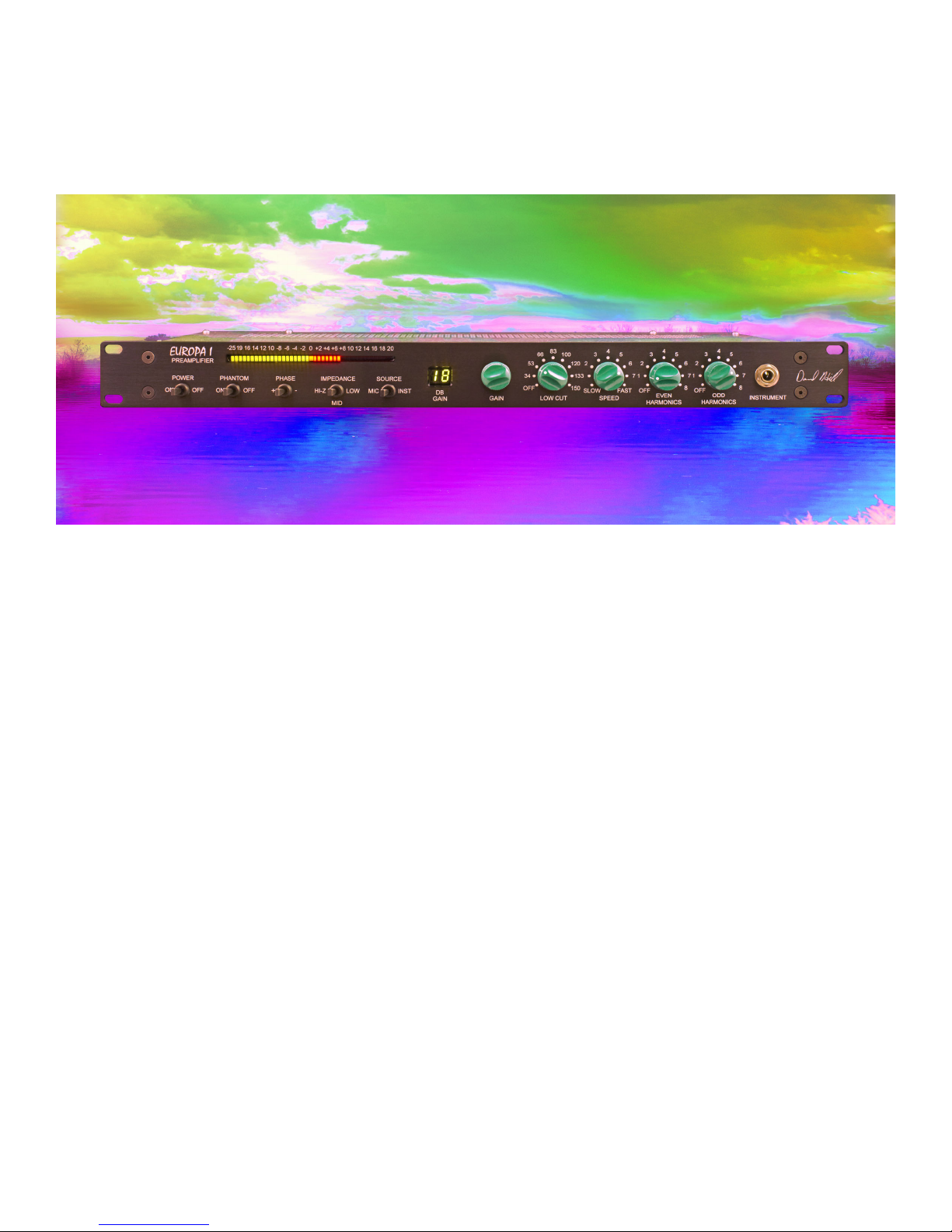
EUROPA I
PREAMPLIFIER
MANUAL VER 1.01
201102025
See the next page for startup switch settings
© 2011 Dave Hill Designs
2117 E5th street
Superior WI USA
54880
davehilldesigns.com
Page 2
Start Up Settings 2
Safety Information 3
Introduction 4
Guided Tour 5
Panel Guide 7
Color-Distortion Curves 8
Filter Curves 12
Specifications 13
SETTINGS TO START WITH
ODD
HARMONICS
SET TO OFF
IMPEDANCE
PHANTOM
POWER
SET TO OFF
SET TO MID
SPEED
SET TO FAST
PHASE
+
SET TO
MIC INPUT
LOW CUT
18 DB/OCTAVE
SET TO OFF
EVEN
HARMONICS
SET TO OFF
Page 3

IMPORTANT SAFETY INSTRUCTIONS
1. Read these instructions
2. Keep these instructions
3. Heed all warnings
4. Follow all instructions
5. Do not use this apparatus near water
6. Clean only with dry cloth
7. Install in accordance with the manufacturer's instructions
8. Do not install near any heat sources such as radiators, heat registers, stoves, or other apparatus
(including amplifiers) that produce heat
9. Protect the power cord from being walked on or pinched particularly at plugs and the point where
they exit from the apparatus
10. Only use attachments/accessories specified by the manufacturer
11. Unplug this apparatus during lightning storms or when unused for long periods of time
12. Refer all servicing to qualified service personnel. Servicing is required when the apparatus has
been damaged in any way, such as power-supply cord or plug is damaged, liquid has been spilled or
objects have fallen into the apparatus, the apparatus has been exposed to rain or moisture, does not
operate normally, or has been dropped
13. CAUTION: To disconnect the unit completely from the MAINS, unplug the unit. Turning the power
switch off does not disconnect the unit completely from the MAINS.
CHECK THE LINE VOLTAGE SETTING BEFORE PLUGGING THE UNIT IN
Page 4

INTRODUCTION
Europa 1 is a preamplifier that is constructed with 91 transistors in it’s main audio path and it is of
discrete Class A topology. The preamplifier controls are either traditional pre-amplifier type controls
or color controls. It is also necessary to understand that distortion may not sound like what one
normally thinks distortion is. Distortions can be very pleasing colors - sounds.
POWER UP Allow a 20 minute warm up period for optimum operation.
The gain display shows the firmware version on power up, this is the left most digit of the gain display
GAIN The gain control circuit uses some of the latest technology that allows digital gain control over
analog circuits. The preamplifier circuit with it’s gain control elements has 1 db gain steps that range
of 0 db of gain to 66 db of gain. The maximum signal level is +24dbu. Balanced in, balanced or
unbalanced out. The 0 db gain setting allows for post processing during mixing, and eliminates the
need for a pad switch. Gain is displayed on a 2 digit display.
Other standard preamplifier type control functions are also available. They are, phase flip and 48 volt
phantom power.
INPUT IMPEDANCE The input impedance of the mic preamplifier has 3 choices.
The HI-z selection is in the range of 200K ohm and will provide very little loading of the source. The
second position has an impedance of approximately 2.2K ohms. With the third position having an
input impedance of 300 ohms for color choices.
SPEED Speed is the first control in the color set. All color controls are series connected. They
affect each other. The speed control changes the slew rate of the preamplifier. This is the same as
rate of change. The result of this is that low level signals are unaffected, but a large signals that
changes quickly will be slowed down. See wave form photos.
EVEN HARMONICS The even harmonic control changes the amount of even harmonic content.
This is a color that can thicken a sound and is very difficult to describe. This is mostly second
harmonic.
ODD HARMONICS The odd harmonic control changes the amount of odd harmonics that are added
to the audio path. Odd harmonics can make a sound brighter and the way this control works it can
also add detail and a compression effect. The compression happens because of amplifier overload.
LOW CUT The hi-pass filter is a third order 18 db pre octave filter of a type that has good time
domain response. The filter has 8 frequencies 148 Hz, 130 Hz, 117 Hz, 100 Hz, 81 Hz, 63 Hz, 48
Hz, 33 Hz, and off.
INSTRUMENT INPUT The instrument input has 1.2 Meg ohm impedance and has a gain range of 0
db to 30 db
METER The meter is calibrated so that 0VU on the meter is +4 dbu, the top of the meter shows +20
db above +4. The maximum level is +24 dbu.
Page 5

A GUIDED T OUR
a self guided sound test
Controls that change the color or add distortion are always difficult to describe
The Speed control is a control that changes the way the preamp responds to transits. It is a control
that changes the slew rate, it is a rate of change filter. The fast position removes it from the audio
path. This is the default setting.
Low amplitude signals will pass unaffected, but large signals that quickly will be slowed down. The
easiest way to learn what this does is to do an experiment. Apply a snare drum to the preamp; adjust
the level so the peak is at +10 on the meter. Then move the Speed control from fast to a setting of 1
and then to 0. Compare this to the sound with the Speed control set to fast. Now go back and do the
same speed settings but increase the level of the drum until the drum peaks at max level. Note how
the sound changes as the level increases. Rate of change – how much level and how fast.
Now switch to a clean unprocessed voice. Set the Speed control to 5 and slowly increase the level of
the voice from peaking at +4 to max level. Note how it changes as the level increases. I have found
that the settings of 4 to fast to be most useful with vocals. It depends on the level so it can be played
with. Level is one half of the rate of change function.
The Even harmonic control generates mostly second harmonic, but other harmonics as well. It is the
most subtle of the color controls because the second harmonic is the hardest to hear. This control is
also level dependent and will affect the audio more as the signal increases from 0VU to the maximum
level of +20 VU. Try a clean unprocessed acoustic guitar, if you set the control to 8, the maximum
control setting, and increase the level of the instrument, you should hear a change that I would
describe as thickening.
The control for Odd harmonics does two related things. First it adds odd harmonics, but it also
compresses. The odd harmonics and the compression are related. It brings up the low level part of
the signal and brings down the peaks.
Try a clean unprocessed voice if you set the control to 8, the maximum control setting and increase
the level of the voice, you should hear, more detail, and a brighter sound. But compared to the
unprocessed voice, there is a dynamic and transit change. The low level material will be louder, the
peaks will be less. As how the other color controls work, the odd harmonic control is level dependent
and will affect the audio more as the signal increases from 0VU to maximum level.
Page 6

Being the controls are in series, try the a drum and or voice and bring up both the
Speed control and the Odd Harmonic control. Compare this with the unprocessed audio.
The level dependence is that same thing that happens with all vintage analog gear. This is not about
making a color by adding a little LF boost or a little HF cut; it is changes in amplifier linearity.
POWER UP
One thing to note, is on power up, a number is displayed in the left most gain digit. This is the
firmware version number. It takes about 4 seconds for the internal microprocressors to boot up.
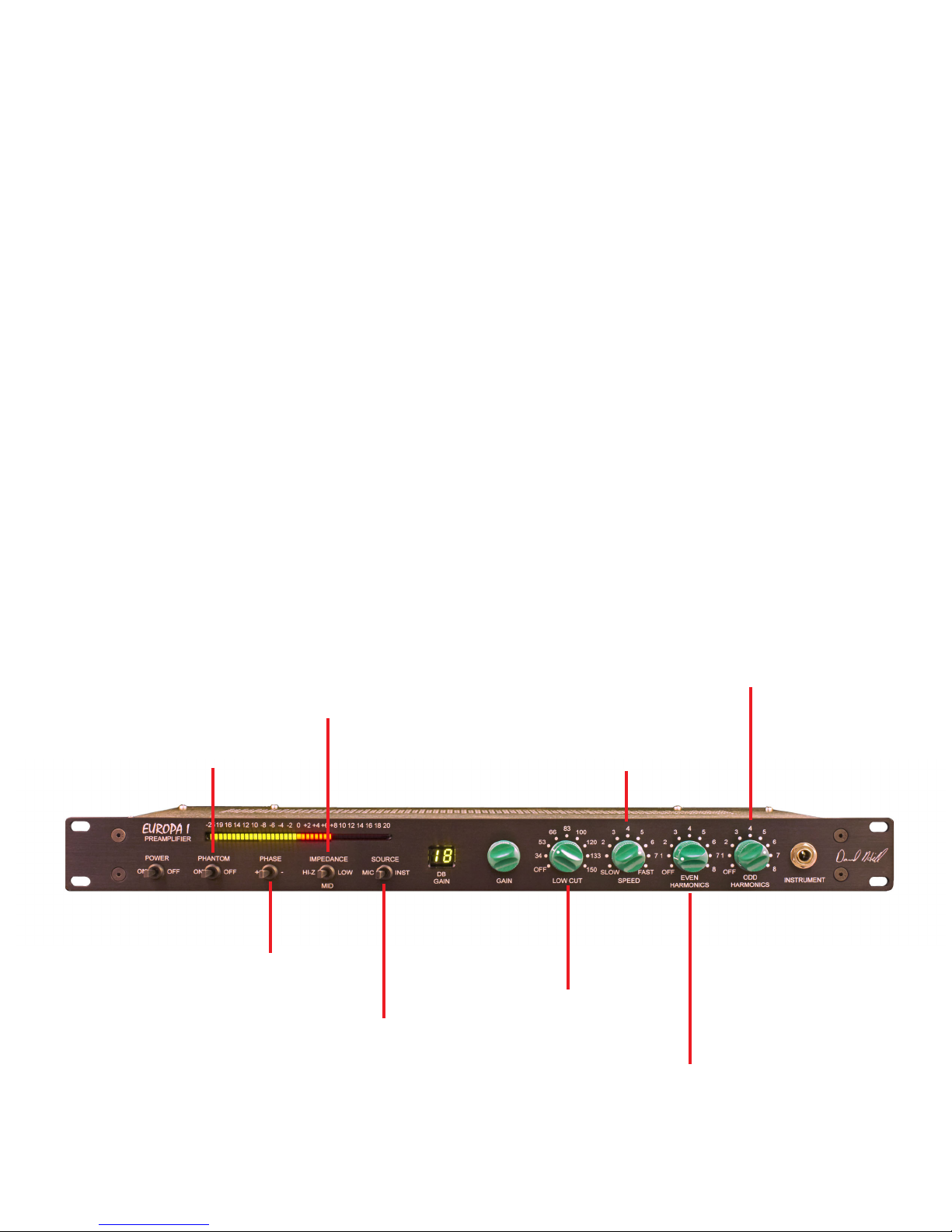
Page 7

PHANTOM
POWER
POWER
MIC IMPEDANCE
HI-Z
2.2K OHMS
300 OHMS
PHASE
MIC -
INSTRUMENT
SELECT
GAIN
MIC GAIN 0 TO 66 DB
HI-Z GAIN 0 TO 30 DB
LOW CUT
18 DB/OCTAVE
ODD
HARMONICS
SPEED
HI-Z
INSTRUMENT
INPUT
EVEN
HARMONICS
LINE VOLTAGE
SELECTION
Page 8

The top wave shape is a vocal recoding
The bottom is the same slowed down by the Speed control;
this is an extreme case to show the effect on the wave shape
SPEED CONTROL
Page 9

FREQUENCY RESPONCE OF WITH THE SPEED CONTROL SET TO 1
NOTE: LOW LEVEL SIGNALS HAVE A NEAR FLAT RESPONCE
HIGH LEVEL SIGNALS ARE CHANGED
SPEED CONTROL FREQUENCY RESPONCE
Page 10

EVEN HARMONIC DISTORTION WITH LEVEL
Page 11

ODD HARMONIC DISTORTION WITH LEVEL
Page 12

LOW CUT FILTER
Page 13

SPECIFICATIONS
Maximum input: +24dbu balanced, +16dbu unbalanced
Maximum output: +24dbu balanced
Hipass Filter:
3 pole, 18db per octave, 8 frequencies 148 Hz, 130 Hz,
1 17 Hz, 100 Hz, 81 Hz, 63 Hz, 48 Hz, 33 Hz
Gain: 0 to 66 db, 1 steps
Gain Insturment Input: 0 to 30 db, 1 db steps
Mic Impedance: 200K, 2.2k, 300 ohms
at gains < 13db the Hi-z position will be around 15K ohms
Insturment Impedance: 1.2 Meg ohm
Noise: EIN -127.5 dbu, 20KHz Bw
Power: 25 watts at 115 or 230 volts, 50 or 60 Hz.
Fuse size is GMD .315A for 115 volts; GMD .15A for 230
volts
for 100 - 120 volts set to 115v
for 220 - 240 volts set to 230v
Shipping Weight: 15 lbs (6.7kg)
Depth Behind Panel: 8.625 inches plus user input/output connectors
Acknowledgements
There are a number on people who have suggested ideas that have helped Europa 1 evolve
into the controllable device that it is.
They inculude; Jean Hund, Raf Lenssens, Michiel Hollanders, Mathijs Indesteege, Niki
Melville-Rogers, Fab and others
 Loading...