

Dave Embedded Systems ARM Cortex-A9 MPCore Hardware Manual
Solo / Dual / Quad
ARM Cortex-A9 MPCore
CPU Module
Line
HARDWARE MANUAL
DAVE Embedded Systems
www.dave.eu
info@dave.eu

A x e l H a r d w a r e M a n u a l v . 1 . 0 . 4
<Page intentionally left blank>
April, 2015 2/78

A x e l H a r d w a r e M a n u a l v . 1 . 0 . 4
Table of Contents
1 Preface.....................................................................................................................................6
1.1 About this manual.............................................................................................................6
1.2 Copyrights/Trademarks.....................................................................................................6
1.3 Standards..........................................................................................................................6
1.4 Disclaimers.......................................................................................................................6
1.5 Warranty............................................................................................................................6
1.6 Technical Support.............................................................................................................7
1.7 Related documents...........................................................................................................8
1.8 Conventions, Abbreviations, Acronyms............................................................................8
2 Introduction.............................................................................................................................10
2.1 Product Highlights...........................................................................................................12
2.2 Block Diagram.................................................................................................................13
2.3 Feature Summary...........................................................................................................14
3 Design overview.....................................................................................................................17
3.1 Freescale i.MX6 application processor...........................................................................17
3.2 DDR3 memory bank.......................................................................................................19
3.3 NOR flash bank...............................................................................................................19
3.4 NAND flash bank............................................................................................................20
3.5 Memory Map...................................................................................................................20
3.6 Power supply unit...........................................................................................................20
3.7 CPU module connectors.................................................................................................20
4 Mechanical specifications......................................................................................................22
4.1 Board Layout...................................................................................................................22
4.2 Connectors......................................................................................................................24
5 Power, reset and control........................................................................................................25
5.1 Power Supply Unit (PSU) and recommended power-up sequence...............................25
5.2 Reset scheme and control signals..................................................................................29
5.2.1 CPU_PORn.............................................................................................................30
5.2.2 Boot_Mode0/1.........................................................................................................30
5.3 Voltage monitor...............................................................................................................30
5.4 System boot....................................................................................................................30
5.4.1 Boot modes.............................................................................................................31
5.4.2 Default boot configuration.......................................................................................32
5.4.3 Boot sequence customization.................................................................................33
5.5 Clock scheme.................................................................................................................34
5.6 Recovery.........................................................................................................................34
5.6.1 JTAG Recovery.......................................................................................................34
5.6.2 USB Recovery.........................................................................................................35
5.6.3 SD/MMC Recovery..................................................................................................35
5.7 Multiplexing.....................................................................................................................35
5.8 RTC.................................................................................................................................36
April, 2015 3/78

A x e l H a r d w a r e M a n u a l v . 1 . 0 . 4
5.9 Watchdog........................................................................................................................36
6 Pinout table............................................................................................................................38
6.1 Carrier board mating connector J1.................................................................................39
6.2 Carrier board mating connector J2.................................................................................43
6.3 Carrier board mating connector J3.................................................................................47
7 Peripheral interfaces..............................................................................................................52
7.1 Notes on pin assignment................................................................................................52
7.2 Gigabit Ethernet..............................................................................................................52
7.3 USB.................................................................................................................................53
7.3.1 USB Host.................................................................................................................53
7.3.2 USB OTG.................................................................................................................54
7.4 Video Output ports..........................................................................................................54
7.4.1 LVDS........................................................................................................................55
7.4.1.1LVDS0...............................................................................................................55
7.4.1.2LVDS1...............................................................................................................56
7.4.2 HDMI........................................................................................................................57
7.4.3 Parallel RGB............................................................................................................58
7.4.4 MIPI DSI..................................................................................................................59
7.5 Video Input ports.............................................................................................................59
7.5.1 Parallel RGB............................................................................................................59
7.5.2 MIPI CSI..................................................................................................................60
7.6 UARTs.............................................................................................................................60
7.6.1 UART1.....................................................................................................................60
7.6.2 UART2.....................................................................................................................60
7.6.3 UART3.....................................................................................................................61
7.6.4 UART4.....................................................................................................................61
7.6.5 UART5.....................................................................................................................62
7.7 SPI..................................................................................................................................62
7.7.1 ECSPI1....................................................................................................................63
7.7.2 ECSPI2....................................................................................................................63
7.7.3 ECSPI3....................................................................................................................64
7.7.4 ECSPI4....................................................................................................................64
7.7.5 ECSPI5....................................................................................................................65
7.8 Raw NAND flash controller.............................................................................................65
7.9 I²C...................................................................................................................................66
7.9.1 I²C1..........................................................................................................................67
7.9.2 I²C2..........................................................................................................................67
7.9.3 I²C3..........................................................................................................................67
7.10 CAN..............................................................................................................................67
7.10.1 FLEXCAN1............................................................................................................68
7.10.2 FLEXCAN2............................................................................................................68
7.11 JTAG.............................................................................................................................68
7.12 SD/SDIO/MMC..............................................................................................................69
April, 2015 4/78

A x e l H a r d w a r e M a n u a l v . 1 . 0 . 4
7.12.1 MMC/SD/SDIO1....................................................................................................69
7.12.2 MMC/SD/SDIO2....................................................................................................71
7.12.3 MMC/SD/SDIO3....................................................................................................72
7.12.4 MMC/SD/SDIO4....................................................................................................73
7.13 PCI Express..................................................................................................................74
7.14 SATA.............................................................................................................................75
7.15 Audio interface..............................................................................................................75
7.16 Keypad..........................................................................................................................75
7.17 GPIO.............................................................................................................................75
8 Operational characteristics....................................................................................................76
8.1 Maximum ratings.............................................................................................................76
8.2 Recommended ratings....................................................................................................76
8.3 Power consumption........................................................................................................76
8.3.1 Set 1........................................................................................................................77
8.3.2 Set 2........................................................................................................................77
8.4 Heat Dissipation..............................................................................................................77
9 Application notes....................................................................................................................78
Index of Tables
Tab. 1: Related documents........................................................................................................8
Tab. 2: Abbreviations and acronyms used in this manual..........................................................8
Tab. 3: CPU, Memories, Buses................................................................................................14
Tab. 4: Peripherals...................................................................................................................15
Tab. 5: Electrical, Mechanical and Environmental Specifications............................................16
Tab. 6: i.MX6 comparison.........................................................................................................19
Tab. 7: DDR3 specifications.....................................................................................................19
Tab. 8: NOR flash specifications..............................................................................................20
Tab. 9: NAND flash specifications............................................................................................20
Illustration Index
Fig. 1: AXEL – Powered by i.MX6 processor............................................................................10
Fig. 2: AXEL – Solo / Dual / Quad core ARM Cortex A9...........................................................10
Fig. 3: AXEL SOM (top view)....................................................................................................12
Fig. 4: Board layout - Top view..................................................................................................22
Fig. 5: Board layout - Side view................................................................................................23
Fig. 6: Connectors layout..........................................................................................................24
April, 2015 5/78

A x e l H a r d w a r e M a n u a l v . 1 . 0 . 4
1 Preface
1.1 About this manual
This Hardware Manual describes the AXEL CPU module design
and functions.
Precise specifications for the Freescale i.MX6 processor can be
found in the CPU datasheets and/or reference manuals.
1.2 Copyrights/Trademarks
Ethernet® is a registered trademark of XEROX Corporation.
All other products and trademarks mentioned in this manual
are property of their respective owners.
All rights reserved. Specifications may change any time without
notification.
1.3 Standards
DAVE Embedded Systems is certified to ISO 9001 standards.
1.4 Disclaimers
DAVE Embedded Systems does not assume any responsibility
about availability, supplying and support regarding all the
products mentioned in this manual that are not strictly part of
the AXEL CPU module.
AXEL CPU Modules are not designed for use in life support
appliances, devices, or systems where malfunction of these
products can reasonably be expected to result in personal
injury. DAVE Embedded Systems customers who are using or
selling these products for use in such applications do so at their
own risk and agree to fully indemnify DAVE Embedded
Systems for any damage resulting from such improper use or
sale.
1.5 Warranty
AXEL is warranted against defects in material and
workmanship for the warranty period from the date of
shipment. During the warranty period, DAVE Embedded
April, 2015 6/78

A x e l H a r d w a r e M a n u a l v . 1 . 0 . 4
Systems will at its discretion decide to repair or replace
defective products. Within the warranty period, the repair of
products is free of charge as long as warranty conditions are
observed.
The warranty does not apply to defects resulting from improper
or inadequate maintenance or handling by the buyer,
unauthorized modification or misuse, operation outside of the
product’s environmental specifications or improper installation
or maintenance.
DAVE Embedded Systems will not be responsible for any
defects or damages to other products not supplied by DAVE
Embedded Systems that are caused by a faulty AXEL module.
1.6 Technical Support
We are committed to making our product easy to use and will
help customers use our CPU modules in their systems.
Technical support is delivered through email to our valued
customers. Support requests can be sent to
support- a xel@dave.eu.
Software upgrades are available for download in the restricted
access download area of DAVE Embedded Systems web site:
http://www.dave.eu/reserved-area. An account is required to
access this area and is provided to customers who purchase the
development kit (please contact support- a xel@dave.eu for
account requests)..
Please refer to our Web site at
http://www.dave.eu/dave-cpu-module-imx6-axel.html for the
latest product documentation, utilities, drivers, Product
Change Notifications, Board Support Packages, Application
Notes, mechanical drawings and additional tools and software.
April, 2015 7/78
A x e l H a r d w a r e M a n u a l v . 1 . 0 . 4
1.7 Related documents
Document Location
DAVE Embedded
Systems Developers
Wiki
Freescale i.MX
6Dual/6Quad Applications
Processor Reference
Manual
Tab. 1: Related documents
http://wiki.dave.eu/index.php/
Main_Page
http://cache.freescale.com/file
s/32bit/doc/ref_manual/IMX6D
QRM.pdf?
fpsp=1&WT_TYPE=Reference
%20Manuals&WT_VENDOR=F
REESCALE&WT_FILE_FORMAT=
pdf&WT_ASSET=Documentatio
n
1.8 Conventions, Abbreviations, Acronyms
Abbreviation Definition
i.MX 6 APRM i.MX 6 Application Processor Reference
Manual
IPU Image Processing Unit
GPI General purpose input
GPIO General purpose input and output
GPO General purpose output
PCB Printed circuit board
RTC Real time clock
SOM System on module
TRM Technical Reference Manual
XELK AXEL Embedded Linux Kit
Tab. 2: Abbreviations and acronyms used in this manual
April, 2015 8/78
A x e l H a r d w a r e M a n u a l v . 1 . 0 . 4
Revision History
Version Date Notes
0.9.0 October 2013 First Draft
1.0.0 November 2013 First official release with XELK
1.0.0
1.0.1 January 2014 Minor fixes
1.0.2 August 2014 Minor fixes
Fixed power-up sequence diagram
1.0.3 November 2014 Minor fixes
Released with XELK 2.0.0
1.0.4 April 2015 Minor fixes
Added BOARD_PGOOD info
Notes on NVCC_EIM_EXT
Released with XELK 2.1.0
April, 2015 9/78
A x e l H a r d w a r e M a n u a l v . 1 . 0 . 4
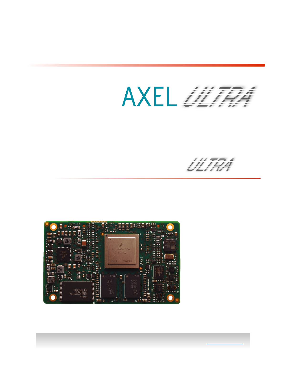
2 Introduction
AXEL is the new top-class
Solo/Dual/Quad core ARM
Cortex-A9 CPU module by
DAVE Embedded Systems,
based on the recent
Freescale i.MX6 application
processor.
Thanks to AXEL, customers
have the chance to save time
and resources by using a
compact solution that
permits to reach scalable
performances that perfectly
fits the application
requirements avoiding complexities on the carrier board.
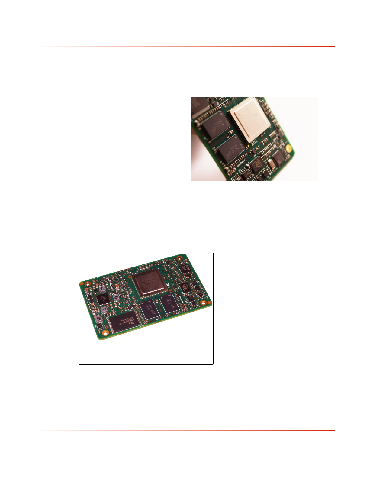
Fig. 1: AXEL – Powered by i.MX6
processor
The use of this processor enables extensive system-level
differentiation of new applications in many industry fields,
where high-performance
and extremely compact
form factor (85mm x
50mm) are key factors.
Smarter system designs
are made possible,
following the trends in
functionalities and
interfaces of the new,
state-of-the-art
embedded products.
Fig. 2: AXEL – Solo / Dual / Quad
core ARM Cortex A9
Scalable ARM Cortex-A9 together with a large set of
high-speed I/Os (up to 5GHz).
AXEL enables designers to create smart products suitable for
harsh mechanical and thermal environments, allowing the
AXEL offers great
computational power,
thanks to the rich set of
peripherals, the
April, 2015 10/78

A x e l H a r d w a r e M a n u a l v . 1 . 0 . 4
development of high computing and reliable solutions. Thanks
to the tight integration between the ARM Core-based
processing system, designers are able to share the application
through the multicore platform and/or to divide the task on
different cores in order to match with specific application
requirements (AMP makes possible the creation of applications
where RTOS and Linux work together on different
cores).Thanks to AXEL, customers are going to save time and
resources by using a powerful and scalable compact solution,
avoiding complexities on the carrier PCB.
AXEL is designed and manufactured according to DAVE
Embedded Systems ULTRA Line specifications, in order to
guarantee premium quality and technical value for customers
who require top performances and flexibility. AXEL is suitable
for high-end applications such as medical instrumentation,
advanced communication systems, critical real-time operations
and safety applications.
April, 2015 11/78
A x e l H a r d w a r e M a n u a l v . 1 . 0 . 4
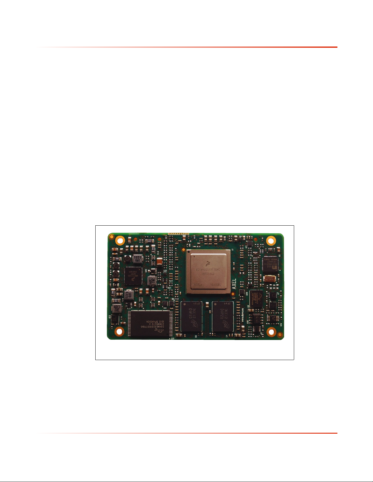
2.1 Product Highlights
● Unmatched performances thanks to Solo / Dual / Quad Core
@ 1.2 GHz
● All memories you need on-board
● Boot from NOR for safe applications
● Enabling massive computing applications thanks to wide
range DDR3 RAM memory up to 4GB
● Wide range PSU input from 2.8V to 4.5V
● High mechanical retention - 100G shock - thanks to
3x140pins and 4 screw holes
● Reduced carrier complexity: dual CAN, USB, Ethernet GB,
PCIe, SATA and native 3.3V I/O
● Suitable for Asymmetric Multicore Processing
● A timing application thanks to on-board 5ppm RTC
Fig. 3: AXEL SOM (top view)
April, 2015 12/78
A x e l H a r d w a r e M a n u a l v . 1 . 0 . 4
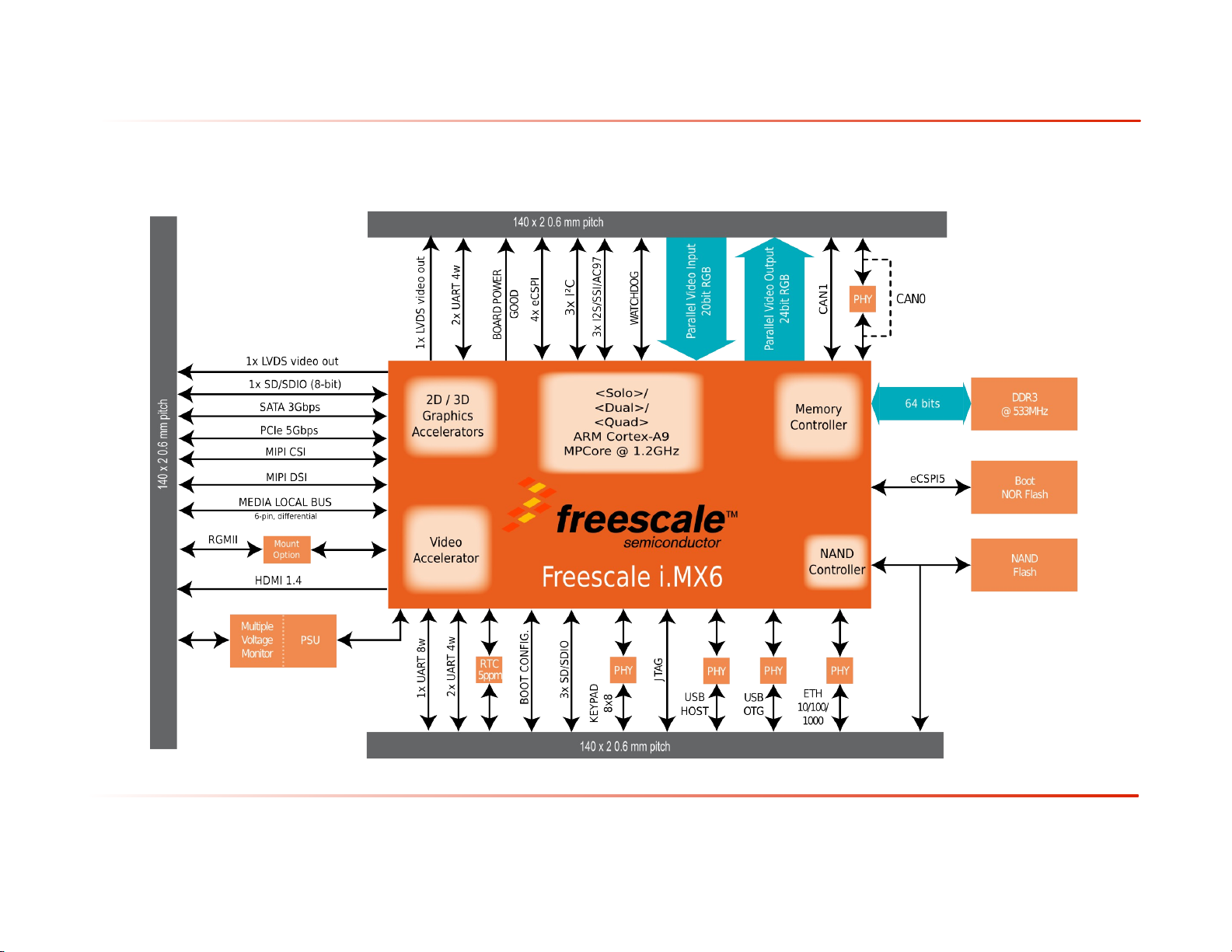
2.2 Block Diagram
April, 2015 13/78
A x e l H a r d w a r e M a n u a l v . 1 . 0 . 4
2.3 Feature Summary
Feature Specifications Options
CPU Freescale i.MX6
ARM Cortex A9 MPCore™ Solo, Dual or
Quad core @ 1.2 GHz
Cache L1: 32Kbyte instruction, 32Kbyte data
L2: Unified instruction and data, 1MByte
RAM DDR3 SDRAM @ 533 MHz
Up to 4 GB, x64 data bus width
Storage Flash NOR SPI (8, 16, 32, 64 MB)
Flash NAND (all sizes, on request)
Expansion bus One PCI Express 2.0 lane with integrated
PHY (5.0 GT/s Endpoint/Root Complex
operations)
Tab. 3: CPU, Memories, Buses
Feature Specifications Options
Graphics
Controller
2D/3D Engines GPU2D cores for raster (R2D, Vivante
Video capture 1x 20bit video input
Video
processing
Coprocessors Media Processing Engine with NEON™ &
USB 1x USB OTG 2.0 with integrated PHY
16-/24-bit HD Display Port
1x HDMI 1.3 channel + DDC
1x TFT/RGB output port
1x MIPI DSI port
2x LVDS output ports
GC320) and vector (V2D, Vivante GC355)
graphics acceleration
GPU3D core (Vivante GC2000) for
OpenGL/OpenGL ES/OpenVG/OpenCL API
acceleration
1x MIPI CSI port
High performance, multi-standard VPU
Up to 1080p60 H264 decode
Up to 1080p30 H264 encode
VFPv3-D32 Floating-Point Unit
1x USB Host 2.0 with integrated PHY
UARTs 5x UART ports (1x full, 4x four-wires)
April, 2015 14/78
A x e l H a r d w a r e M a n u a l v . 1 . 0 . 4
Feature Specifications Options
GPIO Up to 206 lines, shared with other
functions (interrupts available)
Networks Gigabit Ethernet 10/100/1000 Mbps with
integrated PHY
CAN 2x CAN 2.0B ports (1x with integrated
PHY)
SD/MMC 4x SD 3.0 /SDIO 3.0/MMC 4.x compliant
controllers
Storage Serial ATA II 3.0 Gbps with integrated
PHY
Serial buses 5x full-duplex SPI ports with four
peripheral chip selects
3x master and slave I²C interfaces
Audio 3x I²S/SSI/AC97 interfaces
Timers Enhanced Periodic Interrupt Timer
General Purpose Timer
RTC On board, ±3.5ppm (DS3232), external
battery powered
Watchdog On board, configurable timeout
(MAX6373)
Debug JTAG IEEE 1149.1 Test Access Port
CoreSight™ and Program Trace Macrocell
(PTM)
Tab. 4: Peripherals
Feature Specifications Options
Supply
Voltage
Active power
consumption
Dimensions 85mm x 50mm
Weight <tbd>
MTBF <tbd>
Operating
temperature
range
2.8-4.5V wide range input, voltage
regulation on board
See section 8.3 - Power consumption
Commercial: 0°C / +70°C
Industrial: -40°C / +85°C
Shock 100 G
April, 2015 15/78
A x e l H a r d w a r e M a n u a l v . 1 . 0 . 4
Feature Specifications Options
Vibration <tbd>
Connectors 3 x 140 pins 0.6mm pitch
Connectors
insertion/remo
val
<tbd>
Tab. 5: Electrical, Mechanical and Environmental Specifications
April, 2015 16/78

A x e l H a r d w a r e M a n u a l v . 1 . 0 . 4
3 Design overview
The heart of AXEL module is composed by the following
components:
● Freescale i.MX6 Solo / Dual / Quad core SoC application
processor
● Power supply unit
● DDR memory banks
● NOR and NAND flash banks
● 3x 140 pin connectors with interfaces signals
This chapter shortly describes the main AXEL components.
3.1 Freescale i.MX6 application processor
The i.MX6 Solo/Dual/Quad processors feature Freescale’s
advanced implementation of the ARM® Cortex®-A9 MPCore,
which operates at speeds up to 1.2 GHz. They include 2D and
3D graphics processors, 1080p video processing, and
integrated power management. As a result, the i.MX6 devices
are able to serve a wide range of applications including:
● Automotive driver assistance, driver information, and
infotainment
● Multimedia-centric smart mobile devices
● Instrument clusters, and portable medical devices.
● E-Readers, smartbooks, tablets
● Intelligent industrial motor control, industrial
networking, and machine vision
● IP and Smart camera
● Human-machine interfaces
● Medical diagnostics and imaging
● Digital signage
● Video and night vision equipment
April, 2015 17/78

A x e l H a r d w a r e M a n u a l v . 1 . 0 . 4
● Multimedia-focused products
● Entertainment and gaming appliances
The i.MX6 application processor is composed of the following
major functional blocks:
● ARM Cortex-A9 MPCore 2x/4x CPU Processor, featuring:
1 Megabyte unified L2 cache shared by all
CPU cores
NEON MPE coprocessor
General Interrupt Controller (GIC) with 128
interrupt support
Snoop Control Unit (SCU)
External memories interconnect
● Hardware accelerators, including:
VPU -Video Processing Unit
Two IPUv3H -Image Processing Unit
(version 3H)
2D/3D/Vector graphics accelerators
● Connectivity peripherals, including
PCIe
SATA
SD/SDIO/MMC
Serial buses: USB, UART, I²C, SPI, ...
April, 2015 18/78
A x e l H a r d w a r e M a n u a l v . 1 . 0 . 4
AXEL can mount three versions of the i.MX6 processor. The
following table shows a comparison between the processor
models, highlighting the differences:
Processor #
i.MX6 Solo 1 800 MHz
i.MX6 Dual 2 850 MHz
i.MX6 Quad 4 850 MHz
cores
Clock L2
cache
512 KB32 bit @
1 GHz
1 MB 64 bit @
1 GHz
1.2 GHz
1MB 64 bit @
1 GHz
1.2 GHz
DDR3 Graphics
400 MHz
533 MHz
533 MHz
Tab. 6: i.MX6 comparison
3.2 DDR3 memory bank
DDR3 SDRAM memory bank is composed by 4x 16-bit width
chips resulting in a 64-bit combined width bank.
The following table reports the SDRAM specifications:
CPU connection Multi-mode DDR controller (MMDC)
Size min 512 MB
Size max 4 GB
acceleration
3D: Vivante GC880
2D: Vivante GC320
Vector: N.A.
3D: Vivante GC2000
2D: Vivante GC320
Vector: Vivante GC335
3D: Vivante GC2000
2D: Vivante GC320
Vector: Vivante GC335
IPU VPU SATA-
II
1x 1x N.A.
2x 2x Yes
2x 2x Yes
Width 64 bit
Speed 533 MHz
Tab. 7: DDR3 specifications
3.3 NOR flash bank
NOR flash is a Serial Peripheral Interface (SPI) device. This
device is connected to the eCSPI channel 5 and by default it
acts as boot memory.
The following table reports the NOR flash specifications:
CPU connection eCSPI channel 5
Size min 8 MByte
Size max 64 MByte
Chip select ECSPI5_SS0
April, 2015 19/78
A x e l H a r d w a r e M a n u a l v . 1 . 0 . 4
Bootable Yes
Tab. 8: NOR flash specifications
3.4 NAND flash bank
On board main storage memory is a 8-bit wide NAND flash
connected to the CPU's Raw NAND flash controller. Optionally,
it can act as boot peripheral.
The following table reports the NAND flash specifications:
CPU connection Raw NAND flash controller
Page size 512 byte, 2 kbyte or 4 kbyte
Size min 128 MByte
Size max 2 GByte
Width 8 bit
Chip select NANDF_CS0
Bootable Yes
Tab. 9: NAND flash specifications
3.5 Memory Map
For detailed information, please refer to chapter 2 “Memory
Maps” of the i.MX Applications Processor Reference Manual.
3.6 Power supply unit
AXEL, as the other ULTRA Line CPU modules, embeds all the
elements required for powering the unit, therefore power
sequencing is self-contained and simplified. Nevertheless,
power must be provided from carrier board, and therefore
users should be aware of the ranges power supply can assume
as well as all other parameters. For detailed information,
please refer to Section 5.1.
3.7 CPU module connectors
All interface signals AXEL provides are routed through three
140 pin 0.6mm pitch stacking connectors (named J1, J2 and J3).
The dedicated carrier board must mount the mating connectors
April, 2015 20/78

A x e l H a r d w a r e M a n u a l v . 1 . 0 . 4
and connect the desired peripheral interfaces according to
AXEL pinout specifications.
For mechanical information, please refer to Section 4
(Mechanical specifications). For pinout and peripherals
information, please refer to Sections 6 (Pinout table) and 7
(Peripheral interfaces).
April, 2015 21/78
A x e l H a r d w a r e M a n u a l v . 1 . 0 . 4
4 Mechanical specifications
This chapter describes the mechanical characteristics of the
AXEL module.
Mechanical drawings are available in DXF format from
the AXEL page on DAVE Embedded Systems website
(http://www.dave.eu/products/som/freescale/imx6_axel-u
ltra).
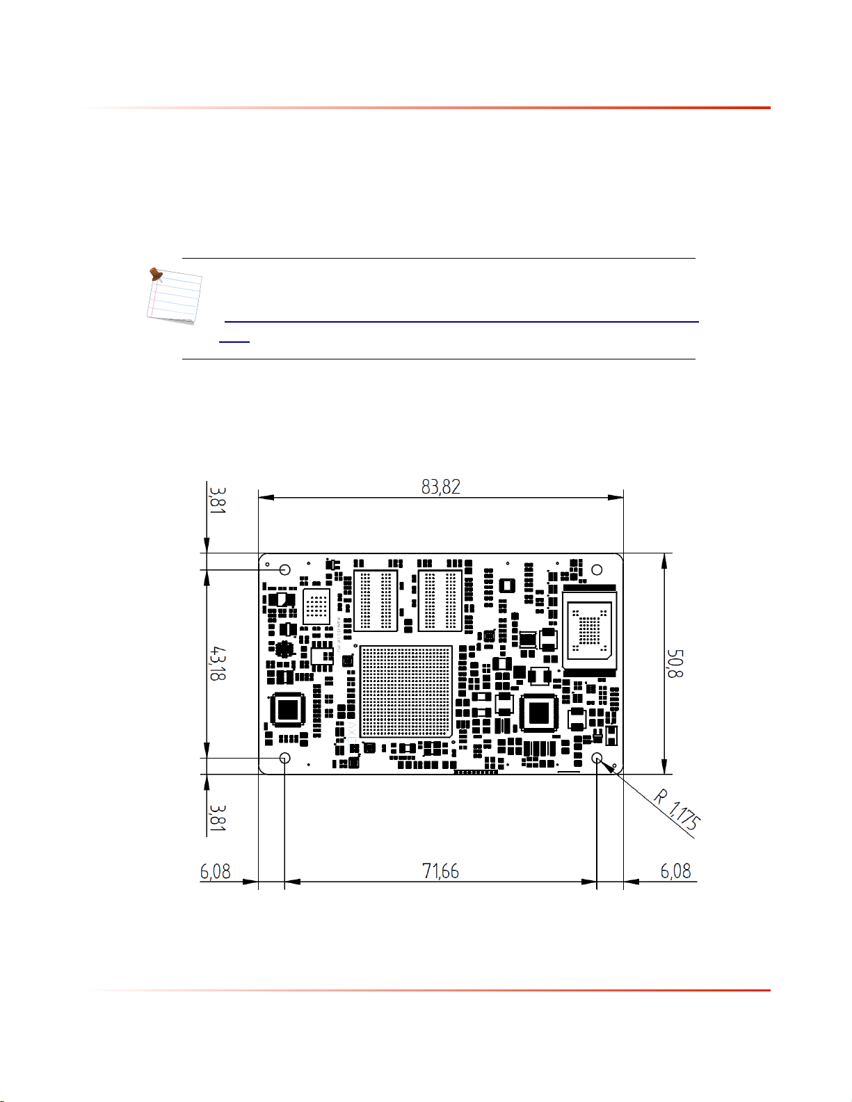
4.1 Board Layout
The following figure shows the physical dimensions of the
AXEL module:
Fig. 4: Board layout - Top view
April, 2015 22/78

A x e l H a r d w a r e M a n u a l v . 1 . 0 . 4
● Board height: 50.8 mm
● Board width: 83.8 mm
● Maximum components height is 2 mm (top) and 4 mm (bottom)
● PCB thickness is 1.9 mm
The following figure highlights the maximum components'
heights on AXEL module:
Fig. 5: Board layout - Side view
April, 2015 23/78

A x e l H a r d w a r e M a n u a l v . 1 . 0 . 4
4.2 Connectors
The following figure shows the AXEL connectors layout:
Fig. 6: Connectors layout
The following table reports connectors specifications:
Part number Hirose FX8C-140S-SV
Height 5.1 mm
Length 48.6 mm
Depth 4.0 mm
Mating
connectors
Hirose FX8C-140P-SV (5 mm board-to-board height)
Hirose FX8C-140P-SV1 (6 mm board-to-board height)
Hirose FX8C-140P-SV2 (7 mm board-to-board height)
Hirose FX8C-140P-SV4 (9 mm board-to-board height)
Hirose FX8C-140P-SV6 (11 mm board-to-board height)
April, 2015 24/78
 Loading...