

Daum electronic Vita 2002 PC de luxe, 8008 TRS User Manual
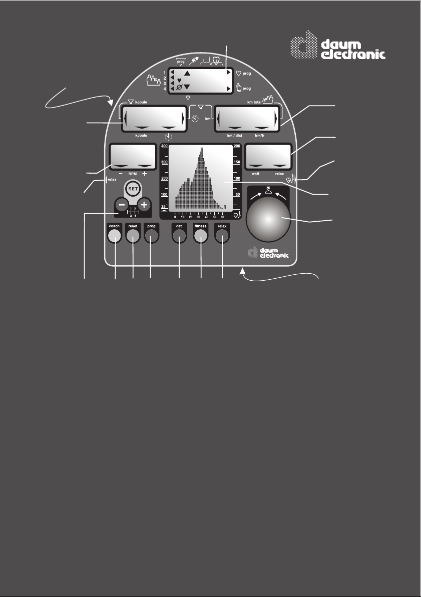
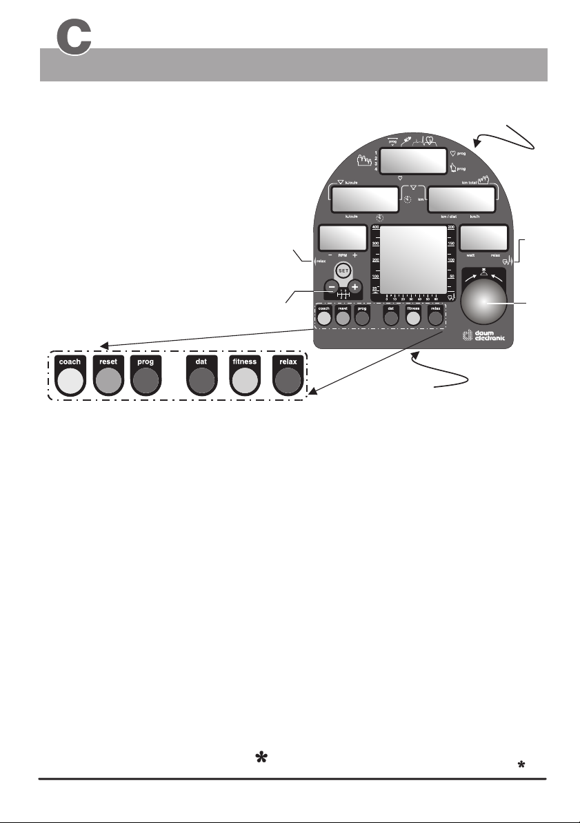
The Dashboard
1
(Underneath)
18
2
88.
88.8
3
7
15
1. LCD-Display
User
Pulse rate
Pulse status
Program number
Program display
3. LCD-Display
14
10
0
OK
.
watt
8
188
)
)
)
:
8
1112
2. LCD-Display
Kilojoule burned
Training time
Fitness grade
Limit values for
Kilojoule burned
and training duration
)
)
)
88.
:
.8
8
4
5
88.8
8
16
6
17
9
13
(Underneath the dashboard)
16. LCD Graphic Display
User number
Program selection
Coaching processes
Relax status
Diagrams / trainings programs
Initialization / time, date
Team Award
Pedal speed
(RPM)
4. LCD-Display
Distance
Total kilometers
per user
Distance covered
Average speed
5. LCD-Display
Braking power in Watt
Relax status
6. Control button
7. Relax sensor connector
8. Pulse sensor connector /
Ear clip
9. fitness key
10. reset key
11. dat key
12. prog key
13. relax key
14. coach key
15. Gear shift
16. LCD Graphic Display
17. PC Interface connector
18. RESET key (recessed)

Table of contents
Fold out page
The dashboard/ Overview of the control
elements
Table of contents
A. Miscellaneous
What is an ergometer?
About this manual
B. Setting up
Switching On/Off
SLP-Mode (Stand by)
C. The dashboard
Control button No. 6
Function keys / input connectors
Window No.1 / Selecting user ID
number and guest user
Window No. 1 / Pulse rate
aerobic pulse zone
Heart pulse rate / aerobic range
Window No. 2 / Time and KJoule
Window No. 3 / RPM
No. 4 / km/h and user km total
Window No. 4 / Distance and km limit
No. 5 / Watt and Relax
Pulse sensor / Cardio Sensor Chest band
PC-interface,
PC-software ergo_win 2002
Manual setting “0”
D. Preparing for training
Setting user identification number
setting personal data and alarm values
data entry, personal settings
E. Training
General recommendations about training
Safety hints about training
Manual training
Fitness test / fitness grade
Recalling fitness and training values
Relaxing / relaxation function
F. Training programs
Programs overview / by model
Programs overview / Setting - display
Selecting the training program
Cardio Program / C
Individual Program / P
Pulse Individual program / IP
Watt Individual program / IL
Speed Individual program / Ir
Selection and programming
Intensification program /L
Constant RPM /A
Strength program /H
Training diagrams watt controlled (400 watts)
Training diagrams pulse controlled
Cool-Down Programs
Cool-Down Diagrams
Training programs watt controlled (400 watts)
Page
FO
A
1
2
3 - 13
3
4
5
6
7
8
9
10
11
12
13
14-17
14
15
14,
16,
17
18-23
18
19
20
21
22
23
24 - 57
24
25
26
27
28 - 30
28
29
29
30
31
31
31
32 - 35
36 - 37
38 - 39
39
40 - 41
Competition circuit
Tour de France (21 stages)
Conconi Test
Conconi Test protocol
Copy models IL / IP / Ir Programs
Gear shift
Starting the training programs at a later point
Determining weight and body fat
ergo_bike Team Award
H. Coaching
General and fundamental information about
Coaching
Preparing for Coaching training
Personal data, performace evaluation
First training, setting the training type
Displaying the training plan and units
Taking performance test (WHO Standard)
Training after the performance test
Running the training units, training control
Deviation from training plan, downgrading
Entry and performance test / WHO Standard
Training samples
i. Initialization
setting the language, time, and date
Dashboard serial number, Team Award
L. LCD Graphic Display
About the graphic display
Sample display screens
M. Assembling the unit
Installation hints / Miscellaneous
Unpacking / contents
Mounting instructions / mounting the feet
Accessory / “swing-feet”
Assembly / mounting the handle column
/ mounting the dashboard
/ mounting the saddle
/ mounting the pedals
Fine tuning
W. Maintenance
Cleaning and care
Simple maintenance and service
Replacing the V-belt
Spare parts / overview (cut away drawing)
Spare parts list
Dashboard replacement
T. Technical information
Special accessory / Cardio Sensor Chest band
Technical data
Safety requirements / conformity
S. Index
G. Glossary / Appendix
Glossary
What to do if.....?
§. Warranty conditions
Page
42
43 - 45
46 - 50
48
51 - 53
54 - 55
56
56
57
H1 - H14
H1 - H2
H2
H3
H4
H5
H6
H7 - H11
H7 - H8
H8 - H11
H12
H13-H14
i1 - i2
i1 - i2
i2
L1 - L2
L1
L2
M1 - M12
M 1
M 2
M 3
M 4-M 7
M 8-M 9
M 9-M10
M 11-M12
M 11
M 12
W1 - W5
W 1
W 2
W 3
W 4
W 5
T1 - T3
T 1
T 2
T 3
S1 - S2
G1-G3
G1
G2-G3
B
A
A

ergo bike
Notes about Software Update
The heart of the dashboard consists of a modern Flash ROM Processor
It allows upgrading all the software related functions, training
programs and fitness tests to the latest release,
even years from now.
The latest software is available for download at the ergo_bike
homepage on Internet and can be transfered to the dashboard
with the ergo_win 2002 PC program
You will find the instructions for this operation in the
that comes with
the software.
“read me” file
Visit us on Internet!
www.daum-electronic.de
Your password for the service area:
“ergo-service”

ergo bike
The present instruction manual describes the
This ergometer is specially designed for health and endurance training. High quality manufacturing, easy to see dashboard, ease of use and maintenance all contribute to make this
appliance an ideal training device for sport and fitness purposes. Also note that the complete
equipment and the wide performance range should appeal to sport or fitness conscious
persons of every age group.
What is an ergometer bike?
The ergo_bike was developped and manufactured in accordance with the standard
A DIN EN 957-1/5 (formerly DIN 32932/A), and is therefore suitable for therapeutic purposes.
The ability to prescribe the required power load in Watt beforehand is an essential
feature of an ergometer.
This load is then maintained independently of the speed expressed in revolutions per
minute (within the RPM ranges shown on the graph on page 9), which means it is possible
to train with a load that is considerably independent of the pedaling RPM. This feature
prevents an unwitting exposure to incorrect loads while training.
A full electronically controlled, maintenance free, eddy current break is at the heart of the
ergo_bike. It adjusts the load according to the values determined by the computer to fit the
strictly personal requirements, and allows a continuous load value selection from 25 to
400 Watt.
ergo_bike “vita 2002 pc de luxe”
The ergometer is thus more than a “Home Trainer”,
since it can be used for both sports and therapeutic objectives.
ergo_bike Model
Introduction
About this manual
The cover of this manual contains a foldout page. This greatly simplifies the general
manipulations and the location of the display and control components on the folded out page.
You will find an explanation of the concepts
and expression that are new to you in the
Glossary in the appendix.
An appropriate symbol is used to identify
various important information and remarks.
Please read them carefully.
1
1
Setting up
General information
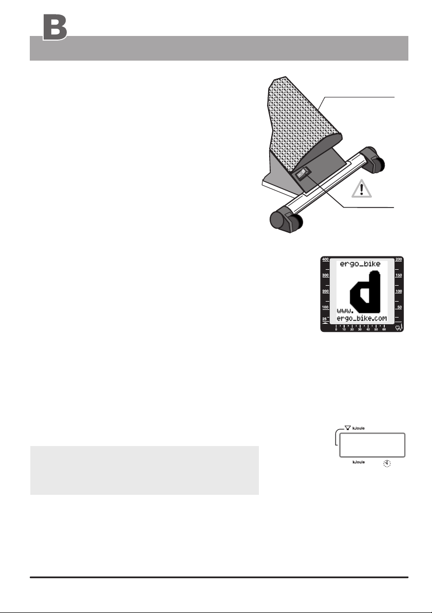
Switching On / Off
U-shaped
perforated plate
Please read the Notes on Safety (page 19)
before switching the ergo_bike on, and follow
the installation and assembly instructions
(pages M1 - M12).
The On/Off switch (power switch) is located
at the back in a rectangular plastic frame on
the rear perforated plate cover.
Upon turning on the power switch (On/Off),
the six display windows of the dashboard
will display all the symbols and number
segments for about eight seconds. This is
On / Off
(power switch)
a self test run by the computer on the entire system.
The dashboard of the “vita 2002 pc de luxe” shows
a Graphic LCD in its centre (see page 4). You will find
LCD Graphic Display
Window no. 6
a special description of this equipment part and
its operation in appendix L (LCD Graphic Display).
The graphic display (window no. 6) provides for more
functional and visual convenience. Displaying training
diagrams, user guidance and hints are functions that
can only be displayed on a graphic display.
watt
See page L1 for
explanation about
the display
The ergo_bike switches automatically to stand by mode if it is left switched on and
unused for about two hours. This is signaled by three beep sounds and ten times blinking
of all the windows, and by the display of “SLP” in window number 2. All other windows
are blanked. This mode is terminated by pressing control button number 6.
The ergo_bike should be switched off by mean of the
On/Off switch or by pulling the power cord plug
Window no. 2
)
)
)
from the power outlet.
Always press the Reset key before switching the
device off in order to save the distance covered
in kilometers.
(This does not apply for the values of the “guest” user.)
Displaywindow
“Stand-By mode” ( SLP )
SLP
Please note:
The value of the daily kilometer counter (the wide arrow pointing to Distance) will
always be added to the total kilometer counter (the arrow pointing to User/Km Total),
1. if the ergo_bike goes in Stand By mode ( SLP-Mode ).
2. or if the Reset key is pressed, or when
3. another person starts a session and another user identification number is selected.
The Dashboard
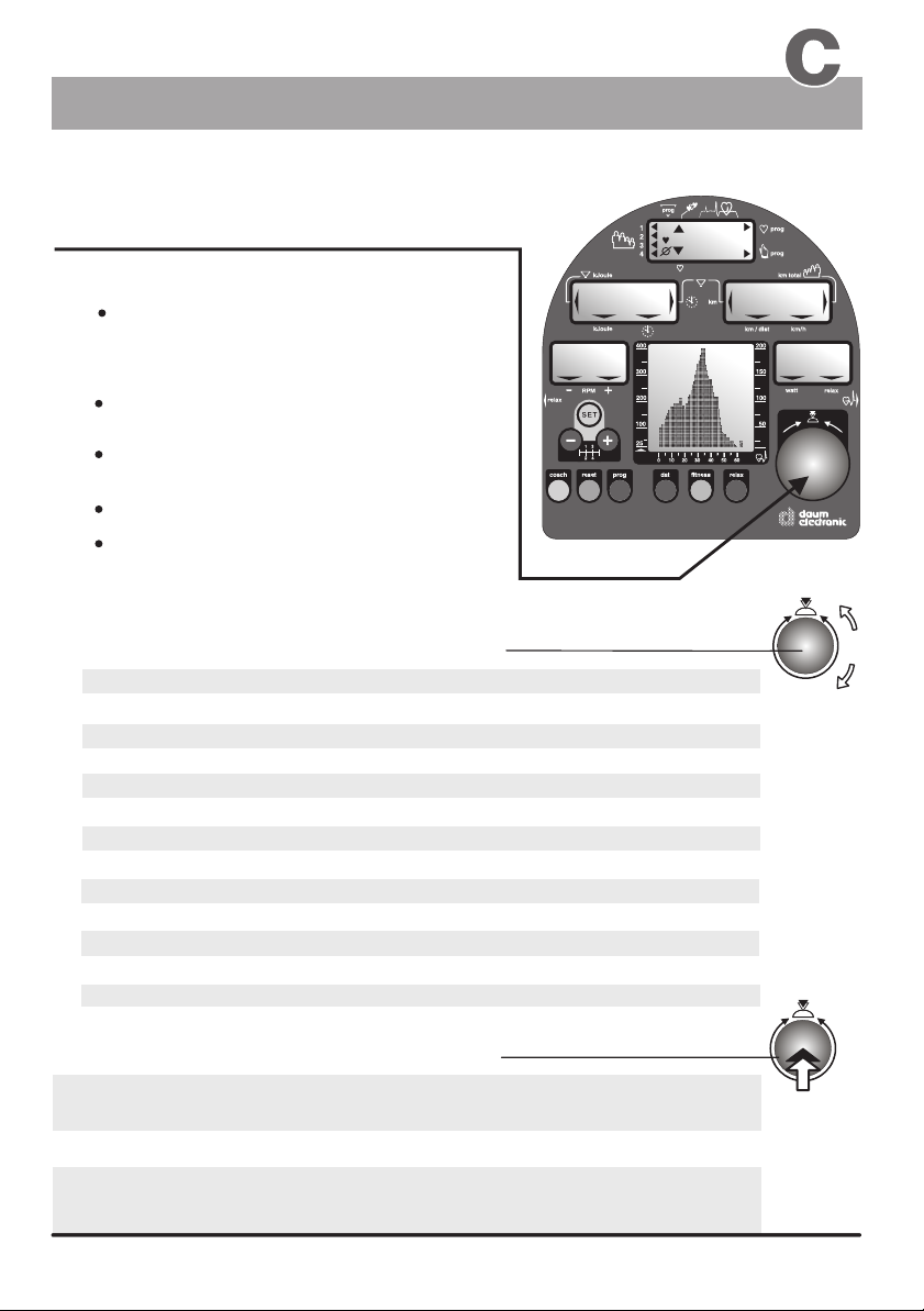
Control Button No. 6
Control button no. 6 is the central control element of the ergo_bike.
Two functions in one button!
Turning the control button:
A:
Changes the value displayed in
the active display window
B:
Pressing the control button:
Activates when in the
SLP mode
Stores the value selected by turning
the button
Changing to the next data to enter
Changing the display between Time/km/h
and KJoule/Distance
Instructions to turn the control button are indicated in this manual
the ergo_bike
Entry / Function A :
Age
Sex
Height
Weight
Body fat content
Individual performance rating
Training frequency
Watts
Pulse rate
Time
Distance
KJoules
Coaching program
Instructions to press the control button are indicated in this manual
in one year increment
Male (M) / Female (F)
in one cm
in 0.5 kg
in 0.5 percent increment
in level unit increment
in number of days
in five watts increment
in one beat per min increment
in one minute increment
in one kilometer increment
in ten kilojoules increment
Menu control / scroll function
increment
increment
Entry mode / Function B :
when setting personal data
when switching or selecting / in general
confirming and storing
of the data (pages 16/17)
)
)
)
88.
88.8
by this symbol
by this symbol
0
OK
188
)
)
)
:
.
8
8
watt
Usage
:
88.
8
.8
88.8
To change the display from Time / km/h
to the display of KJoule / Distance
while training
( see page 8 )
33
The Dashboard
Displays / Function keys / Input connectors
Control elements of the dashboard
1. - 5. LCD Displays
Display windows no. 1 to 5
(see pages 5, 6, 8-10)
6. Control button
(3)see page
7. Connector of the relax sensor
used to connect the relax sensor.
(see page 23 / "to relax" )
7
8. Connector of the pulse sensor
used to connect the pulse sensor /
earclip (see page 11)
14
10
12
9. fitness - key
(has 2 functions / pages 21, 22)
10. reset - key
(see pages 2,14,16, 23, 26, 30, H4, H5, H7)
11. dat- key
(see pages 16, 26/27, H4)
12. prog - key
(see pages 26/27, 39, 31)
11
15
13
9
1.
2.
Resets the display windows.
allows the entry of personal data that will be
used to determine the alarm values to be monitored
during training sessions
This key is used to recall the programmed training
sessions. (see page 26)
18
(below)
Window no. 1
)
)
)
Window no. 2
Window no. 3
watt
)
)
)
16
Window no. 6
LCD Graphic Display
(see appendix L)
Window no. 4
Window no. 5
8
6
17
(below)
Recalls a fitness mark
Recalls the values of the last training session
(see page 21)
(see page 22)
13. relax - key
14. coach key
15. Derailleur control
(see page 23)
(page H4, H6-H7, H12)
(page 54, 55)
16. LCD graphic display
Window no. 6
(see pages L1 - L2)
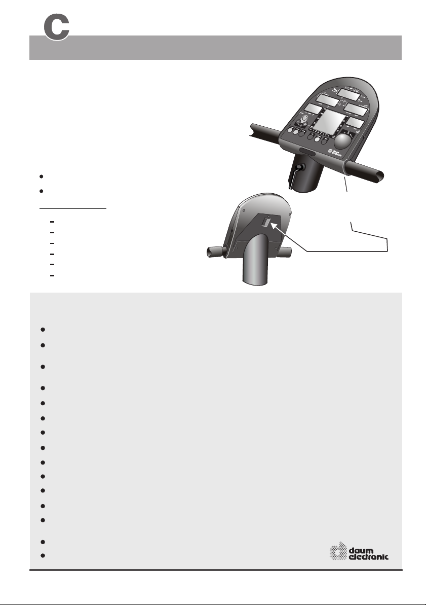
17. Connector
PC-interface
(see page 12)
18. RESET - key (recessed)
for the dashboard computer
4
(see page G3)
what if...?
Starts the relax program used with the relax
sensor (accessory).
Used to set the Coaching program.
keys used to control the electronic “gear-shift” system.
provides functional and visual comfort.
(see appendix L for a description / LCD-Graphic display).
The PC interface (connector) is located on the
underside of the dashboard within the square
opening (see page 12)
The RESET key is located on the underside of the dashboard, above the protective plate and is intended to be used
in the case of a failure of the internal computer software.
The Dashboard
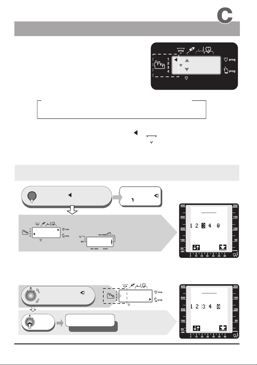
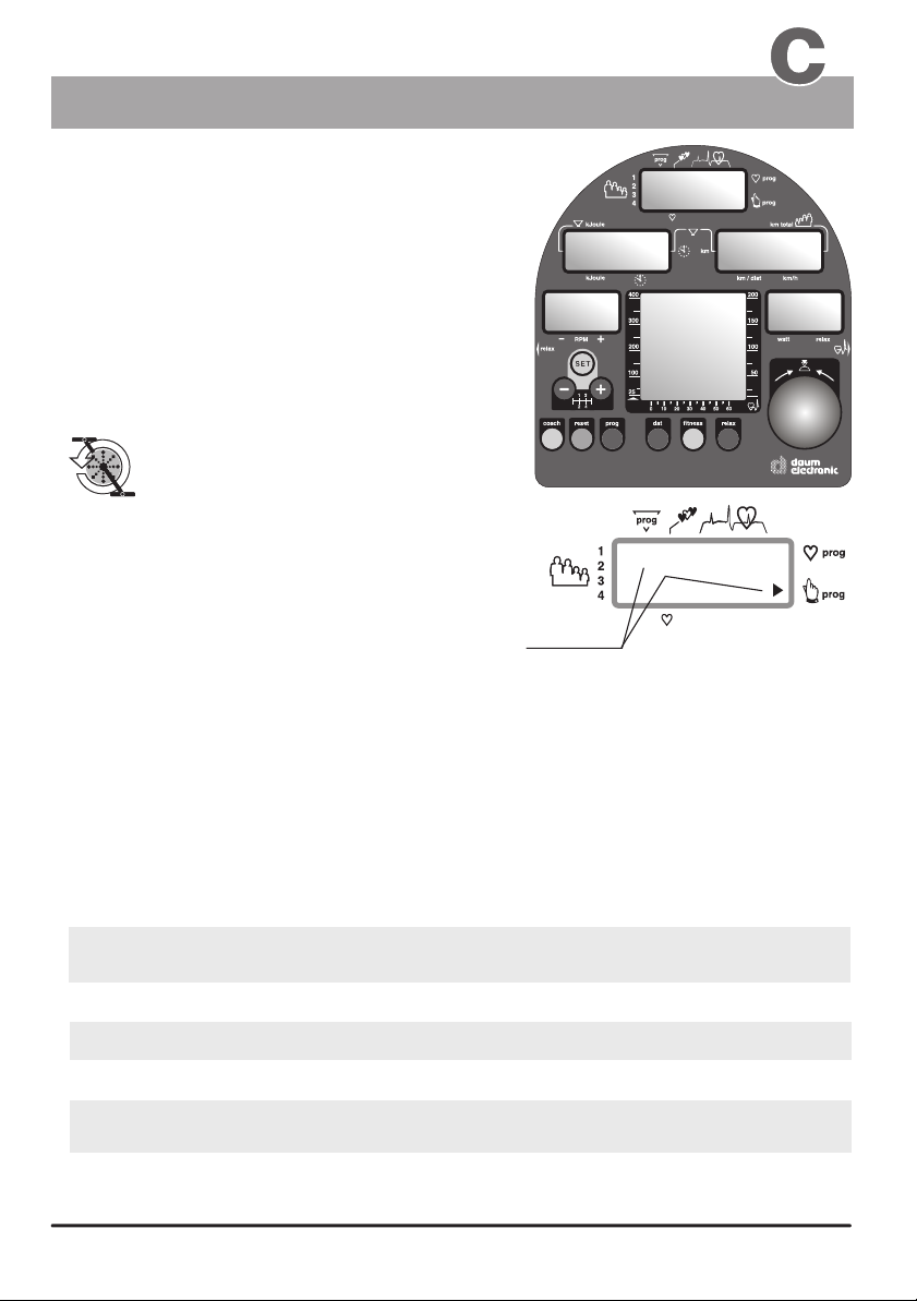
Window No. 1
User instruction
1. Selecting the user
identification number
The ergo_bike computer will record, store and evaluate
the training data of up to four users separately.
Before using the equipment, you must assign
a user number to every user.
The following is an example of a possible number attribution scheme in a family:
Mother Father Daughter
User 1
User 2
Guest users, or any persons, whose training data will not be saved, should use identification
number “0”. When using this ID number the arrow pointing to User 1 to 4 will not
be displayed. Instead the number “0” is displayed under .
No training data will be saved for the “Guest” user when the ergo_bike is turned off!
However, the distance traveled in kilometers will be added to the total kilometer
counter (km-total).
Set up of the User identification number 1 to 4 or Guest 0
reset
press repeatedly until the
user arrow or the “0”
1.
under prog starts to flash
Window 1
CC
- the left arrow points to the
selected user number, e.g. 3
- the right arrow points to
the selected program
and the program number
is displayed under prog, e.g. C
Window 4
)
)
)
3054
- the total number
of travelled kilometres,
e.g. 3054km
Changing the selection
Turn, (to the right or left) until
the blinking user arrow
2.
points to the required user number
or “0” blinks under prog
User 3
prog
Either
the user arrow
blinks
or
00
The graphic display
(window no. 6)
will simultaneously
display the setup
procedure as shown
to the right
Window no. 1
00
00
OK
188
Window 1
Son
User 4
LCD graphic display
(see appendix L)
Window no. 6
User:
watt
Window no. 6
User:
guest
guest
The graphic display
Press
3.
1 x
The settings are confirmed
and saved
User 1 - 4 or e.g. Guest 0
(window No. 6) will
simultaneously display
the setup procedure
as shown to the right.
watt
5
5
The Dashboard
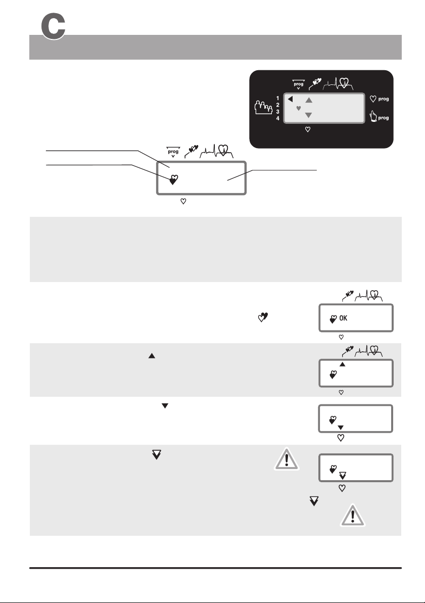
Window No. 1
Displaying the pulse rate
The pulse rate or pulse status
is only displayed if the pulse sensor
(ear clip) or the cardio chest band is
connected or when both hand are holding
the pulse sensors (on the handle).
Selected program
a blinking heart
indicates that the pulse
sensor (ear clip) or the
Cardio chest band
is correctly connected
and functioning,
or that both hands are holding the hand pulse sensors.
00
110
actual
pulse rate
Window No. 1
(simplified representation)
Displaying the aerobic pulse zone
The aerobic zone is a function of the age, it can be determined on the graph
“Target pulse frequency” and the table “target zones of heart frequency” (page 7).
The aerobic pulse zone is only displayed if the user enters his age.
(see page 16 / personal data / alarm levels / age entry )
If the user is training within the aerobic rate zone,
“ OK ” is displayed in window No. 1 (beside the blinking heart ).
00
Heart pulse rate
OK
120
Window 1
110
The upward pointing arrow indicates
that the user is training below the aerobic zone. To get to the “ OK ” zone
the user must either train longer and/or increase
the braking power in Watt.
The downward pointing arrow indicates
that the user is training above the aerobic pulse rate zone.
To get to the “ OK ” zone the user must reduce
the braking power in Watt.
The downward pointing arrow starts blinking
to indicate that the aerobic rate zone is exceeded by an
excessive margin (the danger-zone is reached),
and the user risks injury by overexercising.
A beep sound combined to the downward blinking arrow
indicates that the user has reached the “alarm zone”.
The ergo_bike starts reducing the braking power automatically
at a rate of 5 Watt per second until the pulse rate of the user
falls into the “danger-zone”.
If the training session is program controlled, and if the training is , the watt setting
will automatically reduced by the same reduction needed to bring the pulse rate to the “danger zone”!
6
6
be
blinking arrow!
and
Beep
carried on
199
68
160
60%-75% 76%-85%
86%-100%
40 - 119 120 - 150 151 - 170
171 - 200
40 - 116 117 - 146 147 - 165
166 - 195
40 - 113 114 - 142 143 - 161
162 - 190
40 - 110 111 - 138 139 - 157
158 - 185
40 - 107 108 - 135 136 - 153
154 - 180
149 - 175
40 - 101 102 - 127 128 - 144
145 - 170
40 - 98 99 - 123 124 - 140
141 - 165
40 - 95 96 - 120 121 - 136
137 - 160
40 - 92 93 - 116 117 - 131
132 - 155
40 - 90 91 - 113 114 - 127
128 - 150
40 - 86 87 - 109 110 - 123 124 - 145
OK
100%
85%
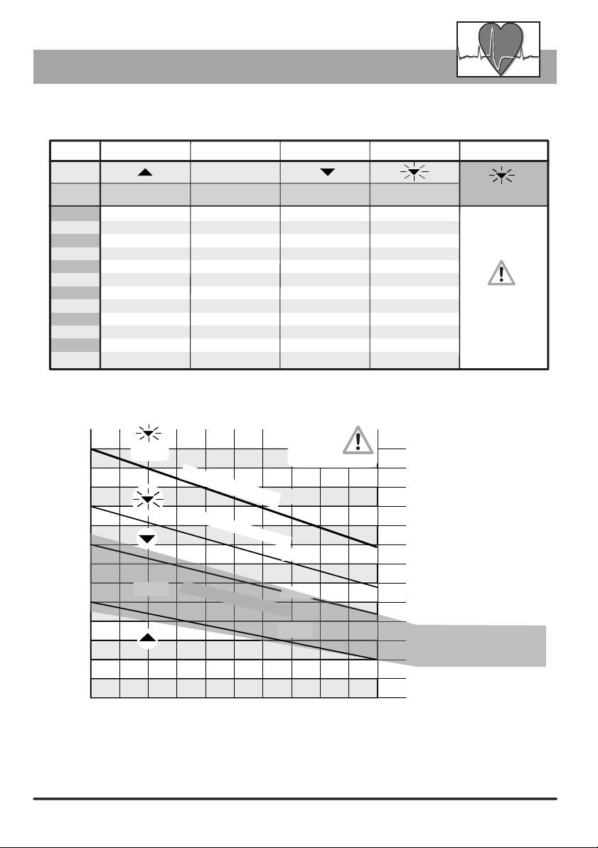
Heart rate frequencies / aerobic zone
Table of target heart rate zone / aerobic zone
Target zone of heat rate frequency to the maximum heart rate
Aerobic Zone
OK
Age
20
25
30
35
40
45 40 - 104 105 - 131 132 - 148
50
55
60
65
70
75
20 0
190
180
170
heart rate
160
150
up to 59%
40 - 119 120 - 150 151 - 170
40 - 116 117 - 146 147 - 165
40 - 113 114 - 142 143 - 161
40 - 110 111 - 138 139 - 157
40 - 107 108 - 135 136 - 153
40 - 101 102 - 127 128 - 144
40 - 98 99 - 123 124 - 140
40 - 95 96 - 120 121 - 136
40 - 92 93 - 116 117 - 131
40 - 90 91 - 113 114 - 127
40 - 86 87 - 109 110 - 123 124 - 145
Overview diagram of the target heart frequency rate
Beep signal
140
130
120
OK
110
100
60%-75% 76%-85%
Alarm Zone
Danger Zone
Aerobic Zone
Health
danger !
100%
85%
75%
60%
90
80
Danger Zone
86%-100%
171 - 200
166 - 195
162 - 190
158 - 185
154 - 180
149 - 175
145 - 170
141 - 165
137 - 160
132 - 155
128 - 150
Alarm Zone
Beep sound
above the
Danger Zone
The braking
power will
automatically
be reduced!
Example
for a person 50 years old
Alarm Zone
Heart rate above 171
Danger Zone
Heart rate 145 - 170
Heart rate 128 - 144
Aerobic Zone
Heart rate 102 - 127
Heart rate 40 - 101
70
20 25 30 35 40 45 50 55 60 65 70
If the braking power is reduced by, e.g., 50 Watt in the danger zone, and the value set for the next
program step is, e.g., 150 Watt, then the training will in fact be carried forward with a load
of 100 Watt, as will be shown in the Watt display (window No. 5). The computer makes this
adjustment as a safety measure.
Age
77
The Dashboard
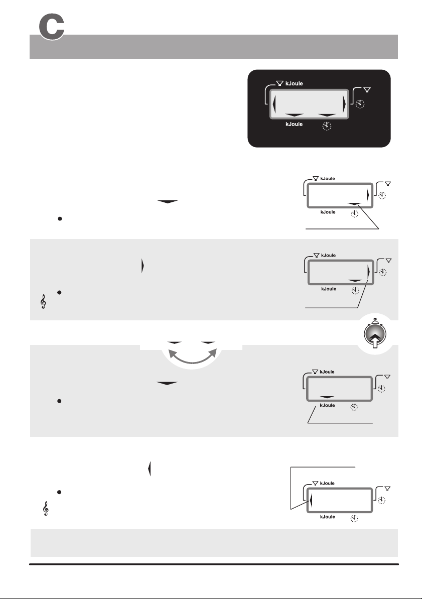
Window No. 2
Displays :
the actual training time
the preselected alarm time
the reaching of a time limit (time limit arrow)
the actual kjoule burned
the preselected kjoule limit
the actual clock time
Training time and kJoule
)
)
)
:
.
8
88.
Display example
Training duration of 30 minutes
8
Window 2
)
)
)
1. Training time
:
When the selection arrow is pointing to the clock symbol:
the elapsed training time is displayed (max. 9 hr 59 min)
(display in minutes/seconds)
1a. Time limit
The time limit arrow is displayed when the preset time
limit is reached.
This arrows indicates that the preset time limit has
been reached or exceeded. Additionally the system
Acoustic signal
Switching between the time and kJoule display using control button no. 6
emits an acoustic signal.
kJoule
kJoule
Time Time
2. kJoule
When the selection arrow points to kJoule then:
the energy spend in kJoule
30
Selection arrow
)
)
)
30
time limit arrow
)
)
)
500
:
0
0
1 x
0
0
)
)
)
)
)
)
)
)
)
)
)
)
is displayed.
Selection arrow
2a. kJoule limit
The kJoule limit arrow is displayed when the preset
kJoule limit is reached.
This arrows indicates that the preset kJoule limit has
been reached or exceeded. Additionally the system
Acoustic signal
(see also pages 14 - 17 / the section on training preparations “personal data / Alarm levels”
or entering the preset values and “Settings verification”)
8
8
emits an acoustic signal.
kJoule limit arrow
)
)
)
500
)
)
)
Watt Relax
The Dashboard
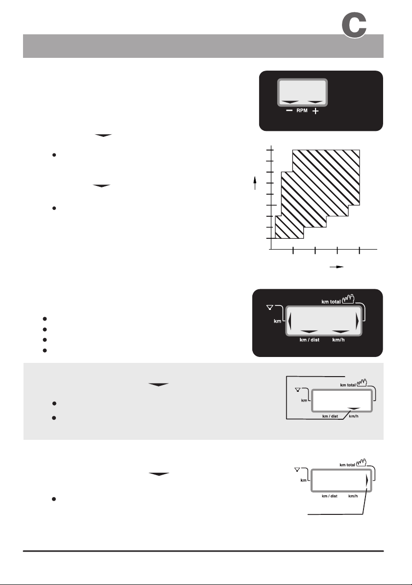
Windows No. 3 & No. 4
Displays:
ergo_bike
The is independent of the RPM in the RPM ranges
shown in the diagram to the right. This means that the user
will have to provide an effort corresponding to the displayed
Watt-power .
The arrow points to the minus sign
to indicate that
The user is pedaling too fast
(It is then possible that the displayed power
in Watt is not exactly true).
The arrow points to the plus sign
to indicate that
The user is pedaling too slow
(It is then possible that the displayed power
in Watt is not exactly true).
The power is indicated precision
of about 10% in the RPM ranges delimited
by the arrows
RPM
, within the actual RPM range
in watt to a
+
__
(Pedals revolutions
per minute)
Displays:
km/h
Users / km total
Distance
The reaching of a distance limit
RPM / km/h and km total
57
Window 3
2
1
0
1
1
0
1
0
0
9
0
8 0
0
7
Speed
6
0
0
5
4 0
0
3
0
2 5
1 0
)
)
)
2 0
Power
3
0
4
0
0
Watt
0
0
100
Window 4
1. km/h
When the selection arrow is pointing to km/h
the displays shows:
the actual speed
the average speed.
(when reviewing the values of the last training session)
2. Users / km total
When the selection arrow is pointing to Users / km total
the displays shows:
the total number of kilometers covered by the user or
under the specified user identification number (for
the whole life of the ergo_bike).
Selection arrow
)
)
)
)
)
)
3054
Arrow
25
99
The Dashboard
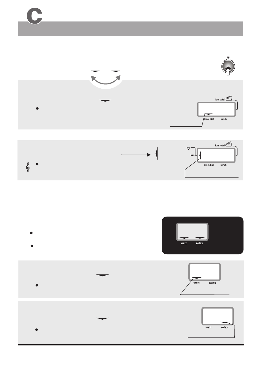
Window No. 4 and No. 5Window
Distance and reaching of a distance limit
Switching between the km/h and distance display using button no. 6
Distance
km/h
Distance km/h
Distance/Watt & Relax
3. Distance
When the selection arrow is pointing to the km/dist:
the distance in km covered during the present training session
is displayed.
Selection arrow
3a. Limit ( km )
)
)
The distance limit arrow is displayed when the preset
distance limit is reached.
acoustic signal
This arrows indicates that the preset distance limit has
been reached or exceeded. Additionally the system
emits an acoustic signal.
)
1 x
15
60
Distance limit arrow
Displays:
the braking power in Watt
a Relax level
1. Watt
When the selection arrow is pointing to the Watt:
the braking power in Watt (25 to 400 Watts)
is displayed.
2. Relax
When the selection arrow is pointing to the Relax:
a Relax level, between 0 and 255
is displayed.
10
10
400
Window 5
150
Selection arrow
180
Selection arrow
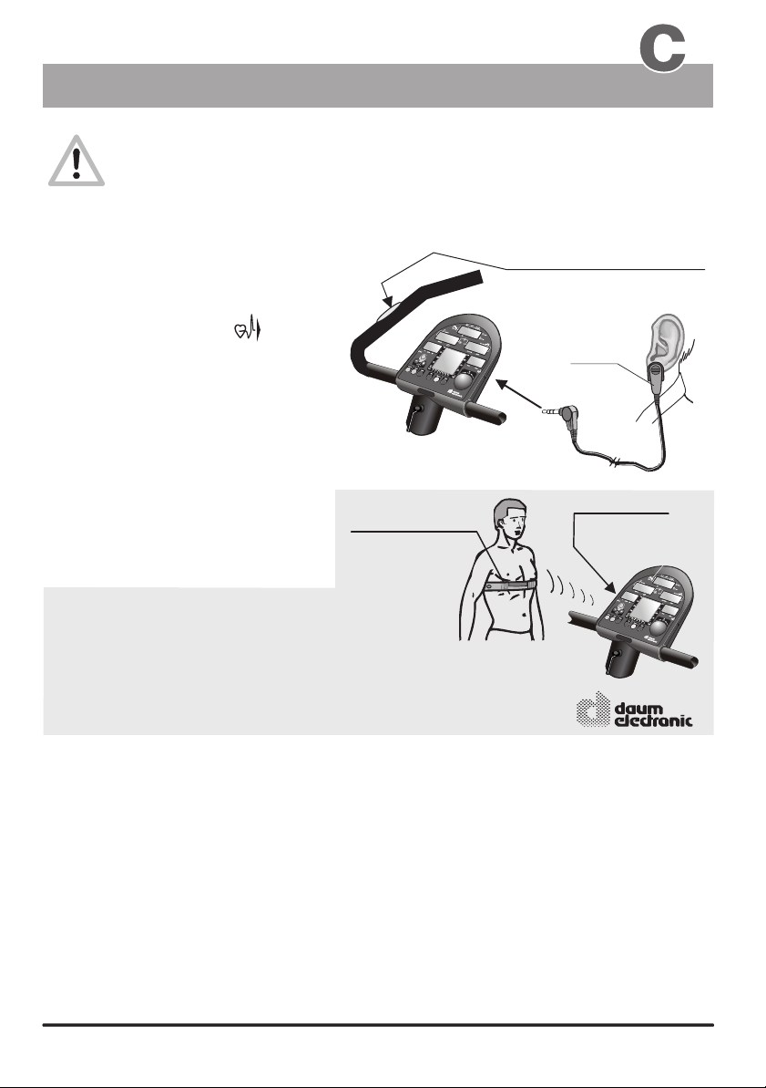
The Dashboard
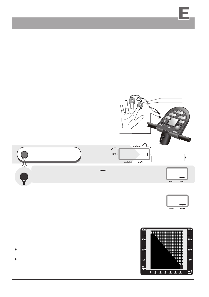
Pulse sensors / Cardio sensor chest band
The pulse sensor (ear clip) included in the package is an important accessory to
the ergo_bike. You should not start any training session without it, or without the Cardio
sensor chest band available as an option ! The pulse sensors built into the handle can
be used to control or monitor the heart rate over short periods of time.
The ear clip pulse sensor illuminates the ear lobe to measure
the pulse rate. Every heart pulse modulates the light passing through the lobe, and can thus be detected
by an infrared sensor and displayed as heart pulse rate.
Pulse sensor (ear clip)
1.
Insert the connector into the socket no. 8
on the dashboard marked with .
2.
You should rub the ear lobe energetically
with your fingers to stimulate blood circulation.
3.
Attach the pulse sensor (ear clip) to
the ear lobe so that the two contact surfaces
sit entirely on the skin. The heart symbol in
display window 1 starts blinking to
indicate that the ear clip is properly attached
and functional!
Warning!
Strong light sources, like sunlight, halogen
projectors or neon lamps, and also ear piercing
or ear rings, and the intake of beta-blocker
could affect the measurements!
The wireless Cardio sensor chest band
(see the figure to the right), available as an
optional accessory (order number 90 91 015),
permits more precise measurements.
( See page T 1 )
You will find a precise description of the display
and the meaning of the corresponding display
symbols on page 6 (Displaying pulse status).
All ergo_bike ergometers are equipped with a built-in, not visible from the outside, Cardio pulse receiver.
This allows receiving of the pulse rate transmitted by any standard chest band, of the coded and noncoded type. You only need a cardio sensor chest band (see page T1) to achieve wireless heart rate
measurement.
Warning: using two chest bands simultaneously in the same room, either of the coded or noncoded type, to achieve wireless heart rate measurement can lead to the display of a wrong pulse
rate on the dashboard of the ergo_bike.
ergo_bike pulse sensor (ear clip)
Standard accessory (included in the box)
Cardio
sensor
chest band
(with transmitter)
wireless
Cardio sensor chest band
Order Nr. 90 91 015
ergo_bike
Special accessory
Pulse measurement over the hand surface
The sensors built in the handle are used to control and monitor the pulse rate over short periods of time. To
achieve a correct measure you should lay your hands relaxed and loose (not tight) on the electrodes. The
electrical resistance of the skin varies as a consequence of blood pressure variations due to heart pulses.
These variations are measured by the electrodes and displayed as heart rate on the dashboard.
Advice:
If measuring the pulse rate over the hand electrodes gives no results, we recommend using
either the ear clip method or the Cardio sensor chest band. The variations of the electrical
resistance of the skin are so small for some persons that they cannot be used to acquire any
usable results.
Built in hand pulse sensor
left and right of the handle
(standard equipment)
Ear clip
connector
Built-in
Cardio pulse
receiver
available from:
111111
The Dashboard
PC Interface
ergo_win 2002
(PC-Software for the communication with the ergo_bike 2002 pc)
The training support provided by the
ergo_win 2002 software was specially
developed for the daum electronic
ergometers of the 2002 pc series.
Comprises:
CD-Rom
Interface cable
Hardware requirements (minimal requirements)
Pentium processor
20 MB free hard disk space
Available serial (Com) port
CD-ROM drive
Keyboard
Operating system: Windows 98 / ME
Features highlights:
Internet capable.
Animated races against oneself, against a computer opponent, against another
ergometer or an internet training partner in real time.
Uncountable number of training programs through exchange and
download possibilities over Internet.
Extremely simplified programming of your own watt and pulse controlled program profiles.
Tour planing for distance controlled training programs.
Extended weight and body fat analysis.
Fully automatic Conconi test / PWC test
Extended training evaluations
Possibility to export all the data to other programs, e.g. Excel.
Extended Coaching functions
User management with individually configurable user interface.
Saving, evaluation and archiving of all the training data.
Provides a wealth of background information on topics of sport medicine
and sport physiology.
Modern user interface.
Simple operation.
Windows 2000 / NT
Order Nr. 90 91 012
Description
Connector
(Underside)
17.
PC Interface
order from:
1212
The Dashboard
Display windows
Manual setting “0”
)
)
)
Window no. 2
Basic set up
Window no. 1
)
)
)
Window no. 4
When the ergo_bike is switched on (using
the power switch), or when the “SLP” state
(sleep mode) is canceled using control
button No. 6, it goes into ready state.
You can directly start training without
the need to do any particular setting!
This symbol means start
operating / turning the
pedals.
The following symbols/numbers in display
window no. 1 mean that the ergo_bike is set
Window no. 3
Window no. 6
LCD Graphic Display
(see appendix L)
watt
00
Window no. 5
in manual mode for the indicated user number,
and without the entry of any personal alarm values:
Symbols
Window no. 1
When you start moving the pedals display windows no. 2,
4 and 5 show the actual training values.
The smallest load value for a training with the ergo_bike is 25 Watts.
You can increase or decrease the load in five Watts increments by turning the
control button no. 6.
The pulse frequency will be displayed in window no. 1 when the pulse sensor (ear clip),
or the Cardio Sensor chest band, is connected and functional or when both hands are laid
on the hand pulse sensors on the handle.
Values displayed in the dashboard windows during a training session:
Window no. 1
Window no. 2
Window no. 3
Window no. 4
Window no. 5
Heart pulse rate
(ear clip) or the Cardio Sensor chest band is connected and functional)
(this value is only displayed if the pulse sensor
the elapsed time since the beginning of the training.
RPM the actual speed of the pedals in revolutions per min.
the actual theoretical velocity (km/h)
the actual load setting (in Watt)
and the Relax levels
Window no. 6
graphical representation of the training session
and operating menus
13
Preparing for training
Personal settings
Training
1. User identification allocation
Selection of the user ID number User (1 to 4) + Guest
1.1
The computer of the records, saves and evaluates, separately the training
data of up to four users (user identification number 1 to 4).
Additionally, guests or other users, whose training data should not be stored,
can train under user identification number “0”.
(see page 5)
reset
press repeatedly until the
user arrow is blinking
1.
in window no. 1
Window no. 1
11
ergo_bike
- The left side arrow points
to the selected user number,
e.g. User number 3
- The program number
is displayed under prog
User arrow
blinks
Window no. 4
)
)
)
3054
- the total number
of traveled kilometers
Window no. 6
User:
guest
watt
The graphic display shows
the number 3 in reverse
(negative). This means user
number 3 is selected.
See page 5 for a more detailed description of the setting procedure,
see appendix L for explanations about the graphic display.
2. Setting up personal data and alarm levels
Training efficiency and control of over and under loading can only be
achieved when the personal data are entered.
The computer of the ergo_bike compares these entries with the actual training
values and evaluates them accordingly.
Possible entries:
DF = Default value
Age
Sexe
Height
Weight
Body fat content
personal performance
evaluation
Entry sequence
for the alarm values
Training frequency
Watt upper limit
Upper limit for
heart pulse rate
training duration
distance
Kilojoule burning
See the notes about evaluating your own performance level
About the age entry
in chapter H (Coaching), page H3.
Every user should always enter his age when training with the ergo_bike, since it is a significant
figure for the determination of the load requirement and for the corresponding fitness evaluation.
for example 45 years
(from 10 to 99)
male / female M or F
for example 180 cm
for example 70.0 kg
for example 30.0
for example 0 = beginner
(from 100 to 220)
(from 30.0 to 150.0)
(from 0.0 to 55.0)
(from 0 to 3)
3 = very well trained
for example 4 days
for example 200 Watt
for example 115 beats
(Confirm with a physician and do not exceed
the recommended value )
for example 25 min.
for example 15 km
for example 350 kJoule
(from 3 to 7 days)
(from 25 to 400)
(from 80 to 220)
(from 00:00 to 99:99)
(from 0 to 99)
(from 0 to 1000)
DF 40
DF = F
DF 180
DF 70,0
DF 30,0
DF 0
DF 3
DF400
DF 220
DF 00:00
DF 0
DF 0
14
14

Preparing for training
Setting up the personal data and alarm levels
About the sex and height
This data completes the profile stored by the computer for each user. And even the minimal difference in
capacities due to the sex has an important impact.
About the weight
The weight has an important impact in the training for fitness improvement, and in the global physical activities.
The user should therefore enter this value consciously, in order for the training to be properly measured and
evaluated. The weight can be entered or adjusted daily (see page 56). Thus, the fitness evaluation function can
produce more precise data about the training results.
About the body fat content
You should use a good body fat analyser, available commercially, to determine the body fat content value. The
measured values (between 0% and 55%) can be entered daily in the computer of the (see page 56).
The default value (DF) is set at 30%.
About the personal performance evaluation
Here the user is required to evaluate his or her own performance capacities. The user must grade his
performance according to the following scale 0 -1 - 2 - 3. Where grade 0 means the user is a beginner and
grade 3 means the user is a very well trained sportsman. (See also the information about your own
performance evaluation on page H3 in the chapter about the Coaching program).
About the Watt upper limit
If an upper limit for the load in Watt is entered (devault value/ DF = 400 watt), then the pulse controlled
programs will raise the load up to this limit. No further increase of the load will occur when the entered limit
is reached, even if the pulse rate did not yet reach the target value.
This also applies to all types of programs (watt, speed, manual, RPM, etc.), as the load
in watt will not exceed the value entered for the limit.
About the pulse rate limit
Users should preferably consult a physician to determine the reasonably acceptable personal pulse rate.
(see also page 7 / Table and diagram of the target pulse rate)
Rule of thumb to
determine the pulse rate limit:
The warns you when the limit pulse rate is exceeded and the danger zone is reached, by displaying
ergo_bike
a blinking arrow in window no. 1, and by an additional beep sound when you enter the alarm zone.
(see pages 6 and 7 / aerobic pulse zone and target pulse rate)
for burning fat
for endurance training
160 - ( minus ) age = pulse rate
200 - ( minus ) age = pulse rate
About the duration of the training, distance and kJoule burned
These data / alarm value entries determine indirectly when a training program is terminated, i.e. when A - a time
limit, B - a distance limit or C - a limit value of kJoule to burn is reached.
ergo_bike
2.0 Data entry and alarm levels set up
The dashboard of the ergo_bike permits the entry of personal alarm levels for pulse rate, upper watt limit,
training time, distance and burned KJoule. When an alarm level is reached during training, a beep signal is
sounded and the corresponding limit arrow is displayed. If you continue training, the beep signal stops, and
only the arrow indicates that the corresponding alarm has been reached.
If the alarm level of the pulse rate is reached or exceeded, the ergo_bike reduces automatically the braking
power in five watts per second increments until the actual pulse rate falls below the alarm level.
The entry of the age is mandatory for the display of the aerobic pulse zone for the user.
(see page 6)
The manual program must be selected before the entry of the data or alarm levels, otherwise
the entry of the pulse rate level will be skipped.
15
Preparing for training
Personal settings
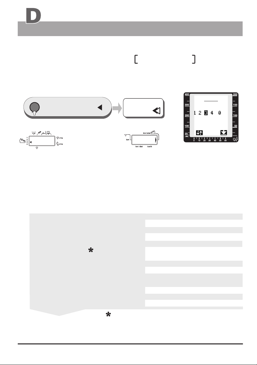
Entry procedure tor
the personal data and alarm values
Window no. 4
)
!
Arrow
)
)
0
reset
press repeatedly,
until the km total arrow is
1.
displayed in window no. 4
dat
press
2.
1 x
The value displayed for km total will be 0 km when setting up
a new device. Otherwise, the number of kilometres accumulated
for the respective user (1 to 4) will be displayed.
window no. 6 displays
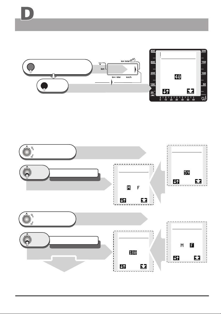
2.1 Age entry
Turn until the age
of the user (e.g. 40)
is correctly displayed
press
1 x
next setting / sex
The setting is confirmed
and saved
Alarm value for the age 59 years
either accept the DF value 40
or modify the age
Window no. 6
data user 1
sex
Training
Window no. 6
data user 1
age
watt
The devault setting is
40 years (DF)
Window no. 6
data user 1
age
2.2 Sex entry
Turn until the sex
of the user is
correctly displayed
press
1 x
next setting / height
2.3 height entry
16
16
The setting is confirmed
and saved
Alarm value / Sex F
(see page 17)
either accept the DF value F or
modify it
Window no. 6
data user 1
hight
Window no. 6
data user 1
sex
Preparing for training
Personal settings
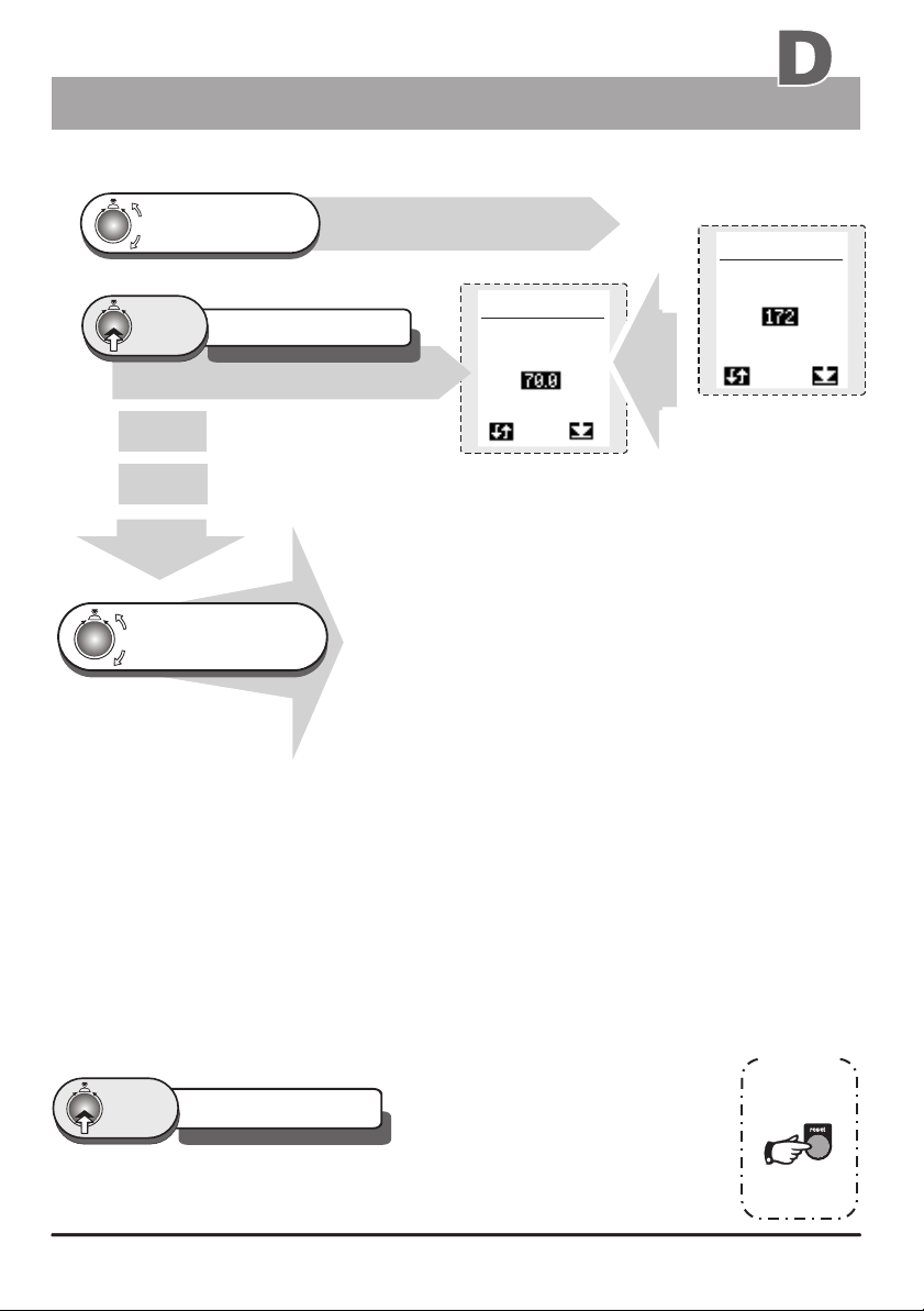
2.3 Height entry
Turn , until the actual
height
is correctly displayed
press
1 x
next setting / Weight
Turn, until the alarm values
or the required personal data
is correctly displayed
The setting is confirmed
and saved
Alarm value / Height 172
The entry procedure is repeated for all the remaining alarm values
to enter
either accept the DF value 180
or change the height value
Window no. 6
data user 1
weight
2.4 weight entry
2.5 Body fat content entry
2.6 personal performance
evaluation
2.7 Training frequency
2.8 Watt limit entry
Training
Window no. 6
data user 1
hight
in kg from 30.0 to 150.0
(Default value 70.0)
Values from 0.0 to 55.0
(Default value 30.0)
Value of 0 to 3
(Default value 0)
Value of 3 to 7 days per week
(Default value 3)
Watt values from 25 to 400
(Default value 400)
2.9 Pulse rate limit entry
2.10 Time entry
2.11 Distance entry
2.12 kJoule entry
Pulse rate value between 80 and 220
Values between 00:00 and 99:00
kJoule values between 0 and 1000
(Default value 220)
(Default value 00:00)
km value from 0 to 99
(Default value 0)
(Default value 0)
The default value will be used to evaluate the training programs for all the values that the user
will not enter
press
1 x
The setting is confirmed
and saved
the procedure to confirm the entered
value is repeated for all the remaining
alarm data entry.
Checking of the entered data is done in the same sequence as their entry.
hint
to quit the
selection menu
press the
reset-key
17
17

Training
Introduction
The ergo_bike makes it possible to define and control the exercise sequence yourself. It is thus
possible to adapt constantly the training plan to the capacities of the user. This device is suitable for
therapeutic use. It does not meet the requirements of medical and diagnostic usage
(in medical clinics).
This ergometer has been essentially designed for endurance, agility and physical condition training and
for strengthening the heart and circulation systems and to help develop the muscular mass. The goal of
such training is to increase the capacity of the body to absorb oxygen, and to improve its overall flexibility.
The inclusion of the pulse rate in the parameters used to control the loading enables training in
the efficient aerobic zone.
Being in the aerobic zone means the muscles loading is at the exact level where they can be adequately
supplied with oxygen without overproduction of lactic acid (aching muscles). Therefore, the ergometer
bike is also a great value for sports medicine and physical education.
The fact that the training effort can be finely measured, gives you
the possibility to carry out physical stress tests to get information
on your physical condition. You can thus identify early any heart
and circulation problems and, with the help of a physician, set up
a special endurance training plan to treat them.
A confortable and relaxed sitting posture are of great
significance for the efficiency and the benefit of the
ergo_bike. You should not be tensed up while training.
You should wear loose sport clothes so that you don't
get into sweat too easily and are not constricted. Your
back should be straight (as opposed to the racing
posture, see fig. B), and your legs should still be
slightly bent at the lower pedal position. This posture
is illustrated in figure A. You should adjust the handlebar
and saddle height and inclination to suit your needs.
Sport physicians recommend preparing for training with relaxing
exercises, which can be followed by some stretching. exercises.
Any user who does not feel completely fit, considering either
the health or physical aptitude aspect, should prepare himself before
training with the ergometer, or consult a physician if in doubt
ergo bike
Handle in
position!
Fig. A
Training properly
Training properly means to load the body reasonably,
in order to achieve the required fitness level
and to retain it.
A lower load will not bring the required effect, while overloading can be dangerous!
Training units per week
Generally speaking, training twice a week will help retain your physical condition.
To improve your fitness level you must train at least three or four times per week.
Therefore, the “Coaching” program will only make sense, and be usable, with more
than 3 training units per week.
You should consult a physician before increasing the number of weekly training units,
to avoid overloading yourself.
18
18
Fig. B
Training
Safety information
Information about personal safety
The ergo_bike ergometer is intended for use by adults. It is not a toy.
Children should only be allowed to train with the ergometer under
adult supervision.
Persons suffering from any of the following diseases should consult their family physician or
a specialist before starting training with the ergo_bike.
Heart disorders like angina pectoris, coronary thrombosis, stenosis, high blood pressure
Diabetes
Respiratory disorders like asthma, chronic bronchitis, etc.
Rheumatism
Gout
or any other disease or illness
You should never train when you feel ill or weak (your own body is often the best sensor).
If a user starts feeling ill or weak, he or she must immediately stop the training, relax
and consult a physician.
Persons who are not used to exercise, and are not used to providing a physical effort
regularly must start with an easy training program, and then increase the load very gradually.
Persons with declared health problems must evaluate their personal risks with the help
of their family physician.
You should never use the ergo_bike to find out your maximum degree of physical
endurance by setting the load in Watt and your pulse rate too high.
This can have serious consequences on your health!!!
The ergo_bike is suitable for therapeutic utilization
(it complies with Class A DIN EN 957-1/5 / formerly DIN 32932/A ).
(It does not meet the requirements for medical diagnosis usage in medical clinics.)
Note
You will find more information about training for sport and health in the pocket book
“Training with the bike ergometer” Improvement of health and fitness as training target
with the ergo_bike.
Order from: daum electronic GmbH, Flugplatzstr. 100 D-90768 Fürth
Fax ++49 (0) 911 75 37 14
Training conditions
You should pay attention to providing good training conditions, this includes choosing the
training room and installation place. Makeshift installation places do not incite to training!
1919
Training
Manual training
ergo bike
Miscellaneous about manual training
Under training program “0” (manual) you can adjust the pedaling effort (braking
power) between 25 and 400 Watts by turning the control button No. 6, and also
change it during the training in 5 Watt increment to adjust the load to your
personal requirements.
Preparing for training
Select the user identification number (1 to 4) or guest
Set personal data and alarm levels (pages 14 to 17)
Where you determine
a) Timed training (Enter an exercise duration as alarm level)
b) Distance related training (Enter a training distance / km as alarm level)
c) Kilojoules related training (Enter a KJoule value as alarm level)
(page 5)
Health and rehabilitation training
This type of training should be performed only according to the time and effort prescriptions
of a physician or therapist.
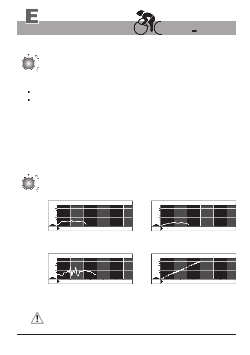
Training examples
The effort settings in Watt can be freely varied according to the performance diagram
selected to “run” and be set according to the represented time intervals.
Beginner program
Beginners Training 2
4
00
0
30
0
2
0
100
0
10 20 30 40 50
23 min / 130 Watt max.
for untrained men up to 70 years of age
15
min
Active sports persons
WATT
Matterhorn
4
00
0
30
0
2
0
100
0
10 20 30 40 50
30 min / 270 Watt max.
for trained users
About the fitness test 25 Watt / WHO-Standard
This exercise takes the user to his/her performance limits. You should only take it after consulting
a physician, and you should interrupt the test immediately at the first sign of discomfort or pain!
10
min
Active Sport Lady
Active Sport LadyWATTWATT
4
00
0
30
0
2
0
100
0
10 20 30 40 50
22 min / 90 Watt max.
for untrained women up to 60 years
Fitness test of the WHO
WATT Fitness test of the WHO
4
00
0
30
0
2
0
100
0
10 20 30 40 50
Fitness test 25 Watt / WHO-Standard
32 Min. / 25 - 400 Watt
(increased in 25 Watts increments at
two minutes interval)
13
min
1
min
20
20
Training
Fitness mark / fitness evaluation
Fitness mark
The can carry out an evaluation your fitness. The measurement principle is based on the
ergo_bike
fact that the pulse rate falls faster within the first minute following the training session for healthy, welltrained users than for healthy, less trained users.
If the user presses the Fitness key during a training session, the present training will be interrupted and
the load will be lowered to 25 Watt within 3 to 4 sec. The graphical screen will display the message
“Fitness mark determination”. The drop in pulse rate within 60sec will be measured (see window no. 2)
and the mark computed according to the following scheme and displayed:
The fitness mark F1 is awarded for a pulse rate drop of more than 25.0% within 60 sec
The fitness mark F2 is awarded for a pulse rate drop of 20.0% to 24.9% within 60 sec
The fitness mark F3 is awarded for a pulse rate drop of 16.0% to 19.9% within 60 sec
The fitness mark F4 is awarded for a pulse rate drop of 12.0% to 15.9% within 60 sec
The fitness mark F5 is awarded for a pulse rate drop of 8.0% to 11.9% within 60 sec
The fitness mark F6 is awarded when the pulse rate drop is less than 8% within 60 sec
The mark of “F0” is awarded if no usable result can be measured.
The training program resumes at the actual position after the evaluation process. The load in Watt is
raised within 3 to 4 seconds to its value just before the evaluation and the training can be continued.
A fitness evaluation is not possible after the training session is finished.
Window no. 6
Fitness evaluation process
A pulse measuring device (pulse sensor / ear clip or the cardio
sensor chest band) must be connected and functional during
the whole fitness evaluation process.
The measuring process takes one minute and its progress is displayed.
1. Train at least 15 minutes in the OK-area (see page 6).
Continue pedalling “loosely” at the load of 25 Watt during
2.
the 60 sec measurement process.
3.
fitness
3.
4.
Press the fitness key only when the two dots in
display window no. 2 are blinking.
The two dots blink during
the training!
Window No. 2 displays an “F”,
and a timer from 1 to 60 seconds during
the .measurement process
fitness
mark
determination
Window no. 2
)
)
)
:
0
0
15
)
)
)
:
6
F
0
)
)
)
)
)
)
)
)
)
)
)
)
5.
After one minute window no 2 displays
the F mark and the system plays a small melody.
F
Example of the display
of fitness mark 2
2
21
21
Training programs
Recalling Fitness and Training Value
Window no. 4
)
)
!
Arrow
)
3054
Window no. 1
11
e.g. User 1
and program no. 1
reset
press repeatedly until the arrow
pointing to km total
1.
is displayed in Window no. 4
press
fitness
2.
Display windows no. 1 to 5 are blanked except for
the user and program arrow or number in window no. 1.
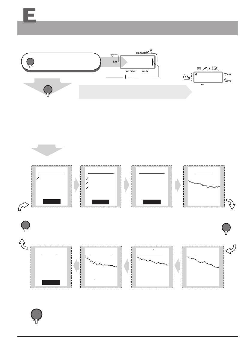
Window no. 6
Press the fitness key to switch form one display screen to the next. The various data screens are
displayed in the sequence represented below. The last data screen (out of 8) displays a summary
of the data per user. For each user, the system sums up the total number of kilometres travelled,
the physical MJoule (=1000kJoule) and the realistic MJoule. In guest mode, the system displays
the sum of the data of the four users together!
Fit. values
o - kmh 25,3
max-kmh 37,8
time 37,58
distance 12,75
Fitness
press the “fitness” key
fitness
to switch from one screen
to the next
(in an endless loop)
totals
phys -MJ 12,3
real - MJ 51,7
time 63,5
distance 1235
Reset
reset
Fig.
A
Fig.
H
Press the reset key to interrupt the display sequence and return to the main menu.
Fig.
B
Fit. values
o - RPM 89
o - watt 240
o - Pulse 132
max-Pulse 168
Fitness
Fig.
G
body fat
year
see also the recommendation about the weight and body fat determination
on page 56 (the entry procedure is described on pages 14 to 17)
Fig.
Fit. values
phys-kj 189
real-kj 431
BMI 26,4
Fit.-mark 3
Fitness
Fig.
weight
body fat
60 days
C
F
Fig.
Weight
60 days
Fig.
Weight
year
D
press
fitness
E
22
Training
Relaxing
The relaxation function
The relaxation function is a Biofeedback-process that is carried out by measuring the electrical resistance of
the skin. The measured values are indicated by means of optical and audio signals.
Biofeedback is thus the translation into perceptible signals of physiological processes occurring in our body, which
our senses can barely, or not at all, perceive. The relaxation function is the ergo_bike's way of helping you relax
and eliminate stress. You should use this option particularly after a physical endurance training.
Connecting the relaxation sensor
1.
Take the velcro bands of the fingers' sensor out of the package and open them.
Place the open tape on one of your fingertip. Make sure there is good contact between the silver buttons and your skin.
2.
The wires from the tape should lead away from the back of your hand.
Put down the side of the velcro tape with the sensor button on
3.
your finger and wrap the other side around it and press it firmly
in place.
Wrap the other tape around your middle finger
4.
in the same fashion.
5.
Plug the connector of the relaxation sensor into the
“relax” input socket no. 7 on the dashboard.
Velcro tape
Sensor button
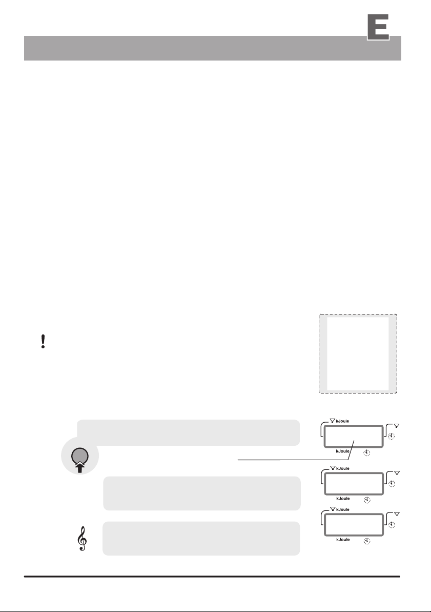
Relaxing
Relax program / process description
reset
Press repeatedly,
until Window no. 4 (right side) displays
1.
the arrow pointing to km total
relax
2.
3.
personal
relaxing
process
The graphic screen displays a representation of the relaxation process. The displayed
line shows the transition from the maximal value (199) to the minimum relax value (0).
This process is also visible in window no. 5. The same process is presented in a graphical
form in window no. 6 (see illustration to the right).
The actual relax level is indicated by a blinking bar in
the display window
The complete relaxing process is divided into 25 levels. A short
beep sound signals when each level is achieved. The successive
beeps are each lower in tonality.
The wide down pointing arrow in Window no. 5
switches from Watt to Relax.
A value is displayed, which starts at 199.
The displayed value drops gradually as you relax after training,
and increases with the stress level.
The Relax-value can drop all the way to almost zero. The user should
therefor contribute to his/her relaxing and avoid any other stress.
You can support this process by getting off the device and sit in
a relaxed position, or lay down close to the ergo_bike and calm down.
Window no. 4
Relax sensor
connector nr. 7
)
)
)
3054
watt
Arrow pointing
to km total
!
199
Window no. 5
Window no. 6
0
23
23

Training Programs
Programs Overview
The following table lists the programs installed in the ergo_bike “vita 2002 pc de luxe”.
ergo_bike Programs
Manual Program
Cardio Program
Individual / P ( IL 60 )
Individual / P ( IL 240 )
Individual / P ( IP 60 )
Individual / P ( IP 240 )
Individual / P ( Ir 60 )
Individual / P ( Ir 240 )
Intensification Prog. / L
RPM Program / A
Strength program / H
Manual / 0
Cardio / C
Watt
Watt
Pulse
Pulse
km/h
km/h
RPM
RPM
braking level
Fixed programs watt controlled
Fixed programs pulse controlled
Fixed programs
(watt controlled / 400 Watt)
Cool Down Programs
Hawaii Competition circuit
No. 1 - 19
No. 29 - 38
No. 20 - 28
No. 42 - 44
No. 39
Roth Competition circuit
Lanzarote Competition circuit
Tour de France / 1997
Conconi Test
Coaching
2424
No. 40
No. 41
stages 1 to 21
No. 45 / 46
Training Programs
Programs Overview
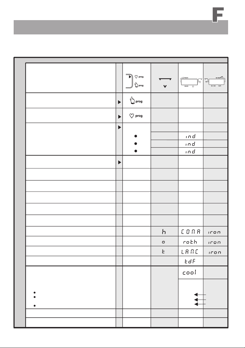
The training programs are identified on the display windows of the dashboard by
the figures, letters or symbols shown below.
Overview / program types
1.
Manual Program / 0
Cardio Program / C
2.
3.
Individual Program / P
(watt controlled)
(pulse controlled)
(speed controlled)
4.
Intensification Prog. / L
5.
RPM Program / A
6.
Strength Prog. / H
Fixed Programs
7.
8.
Fixed Programs
9.
Fixed Programs
10.
Hawaii circuit
11.
Roth circuit
12.
Lanzarote circuit
13.
Tour de France / 1997 1 to 21
(watt controlled)
(pulse controlled)
( 60 / 240 Min. )
(RPM dependent)
(RPM controlled)
(Braking level controlled)
(watt controlled / 400 Watt)
(watt controlled / 400 Watt)
(pulse controlled)
individual IL
individual IP
individual Ir
No. 39
No. 40
No. 41
Setting
Selection Arrow
Individual / P
Intensification / L
Setting
prog
0
C
IL
IP
Ir
L
A
H
1 - 19
r
P
F
Display
)
)
)
No. 2
20 - 28
29 - 38
Display
)
)
)
)
)
)
1 - 21
No. 4
0
1
2
Cool Down Programs
14.
You can attach the cool down programs to
the following programs and use them after the main
program to “cool down”:
- Individual / P (IL / IP / Ir)
- All watt and pulse controlled
fixed programs No. 1 to 41
- All competition circuits
Conconi Test
15.
Coaching
16.
Display no. 6
C
corresponds to
prog. no.
none
42
43
44
E
45 / 46
0 or
1 or
2 or
3
25
25
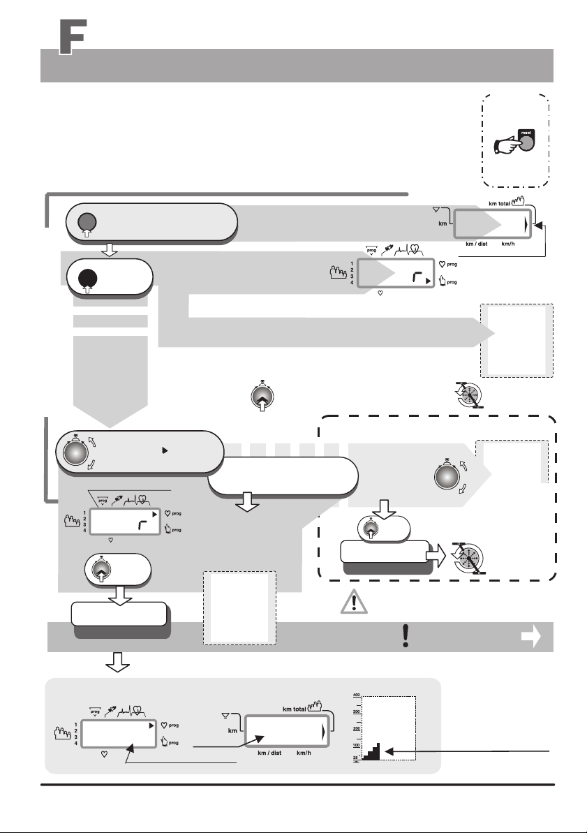
Training Programs
Programs selection
Training Program
Several training programs are stored in the ergo_bike that help automate training sessions.
When running a program, the load will be adjusted, increased or decreased, depending on the
distance, pulse rate or even velocity, according to the watt values prescribed by that particular
program.
The table on page 24 lists the available programs on each ergo_bike model respectively.
Use display windows nr. 1 / nr. 4 and nr. 6 for setting and functions description.
reset
Press repeatedly
until the arrow pointing to km total
1.
appears in window no. 4 (right side)
prog
press
1 x
2.
1 x
only if
you want
to change
the program
Standard Selection Steps 1 to 3
selection
)
)
)
Window no. 4 displays
window no. 1 displays
a big Pr
Manual Program 0
window no. 6 displays the designation of the base program
(manual setting 0)
The ergo_bike operates in manual mode without requiring the selection of a user number
and without the entry of personal alarm values. If you want to train under this setting then
you must press the control button one more time.
This confirms the selection
3.
of the “manual mode”. You can then use
the manual program.
00
P
(see note below)
hint
to quit the
selection menu
press the
reset-key
0
Users / km total
0 km only when
setting a new device
Window no. 6
manual
program
Turn until the
Program arrow points to
3.
the required program on the side
e.g. Cardio program
CC
Anzeige Nr.1
Window no. 1
P
press
4.
1 x
or the number or short description
of the selected program is displayed
under Prog
e.g. setting of the
Cardio / C Program
The graphic display
window no. 6
cardio
The setting is confirmed
and saved
Programm Cardio / C
program
e.g. windows no. 1 / no. 4 and no. 6 display
)
)
)
CC
80
e.g. measured pulse rate for the first minute
e. g. km-total
3054
26
Required program selected?
nein ?
no?
dann
then
turn further
until the required
program
is selected
press
4.
1 x
The setting is confirmed
and saved
e. g. Program .......
When the device is turned off, the selected
program will be saved only for user
identification numbers 1 to 4.
Setting of the pulse
rate upper limit
Window no. 6
watt
Window no. 6
strength
program
for instance setting
of the strength prog.
or any other
fixed program
Run the
selected
program
only for the Cardio / C
Program
The power starts at
25 watts for the Cardio
Program and is
increased by 5 watts
every 15 sec until the
required pulse rate
is reached.
 Loading...