

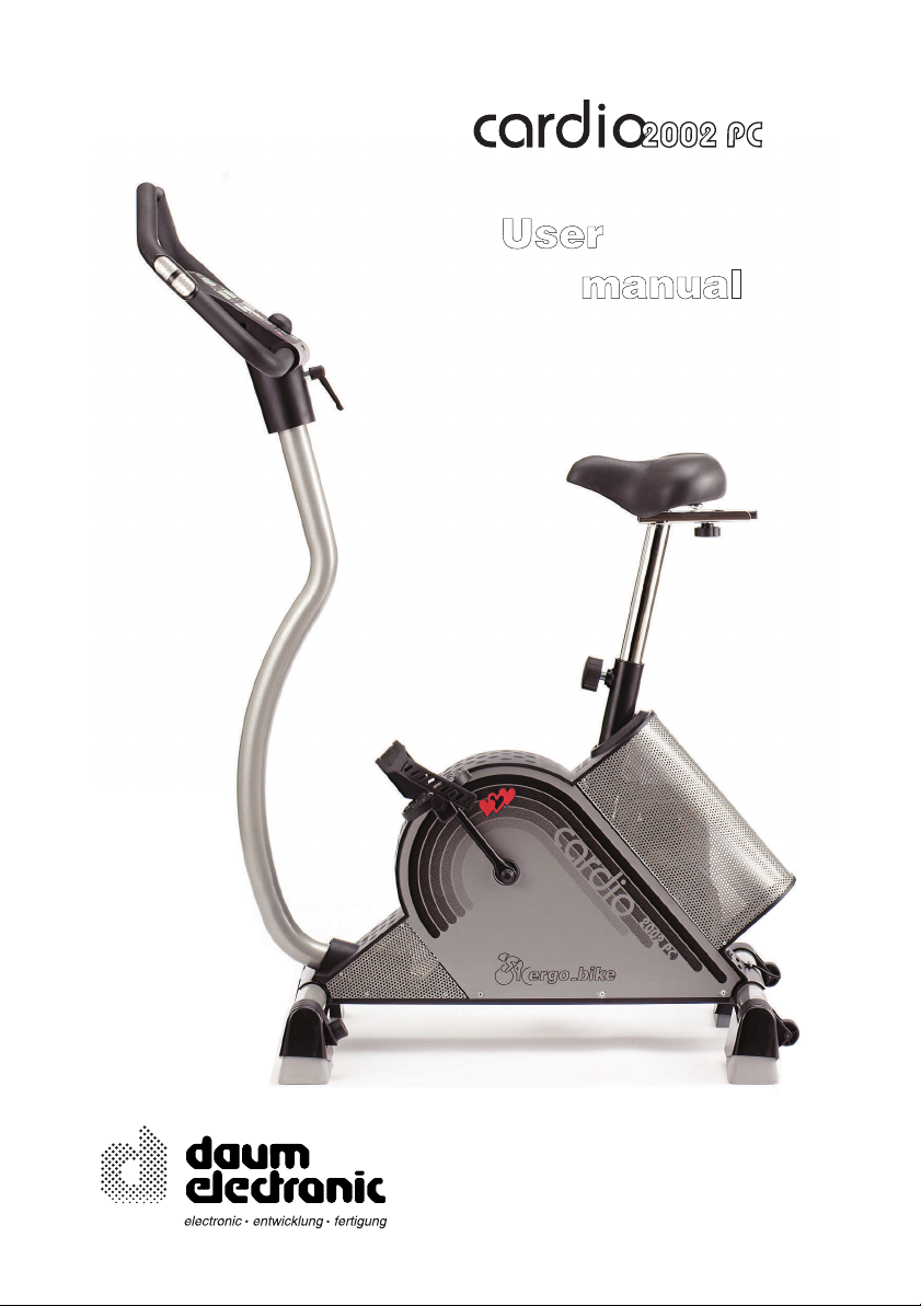
Page 1
Page 2
The Dashboard
(Underneath)
18
)
)
)
:
8
2
88.
88.8
3
7
16
12
10
0
.
8
im Rhythmus Ihres Herzens
Herzfrequenz /
Schläge pro
Minute
200
180
160
140
120
100
80
20 25 30 35 40 45 50 55 60 65 70
Übersichtsgrafik zur Zielpulsfrequenz
watt
OK
188
)
)
)
Bremsleistung wird
automatisch reduziert !
Piepton
Alarm-Bereich
Gefahrbereich
OK
Aerober Bereich
91113
1
88.
Gesund-
heits-
gefahr !
Alter
:
8
.8
88.8
4
5
8
6
17
(Underneath the dashboard)
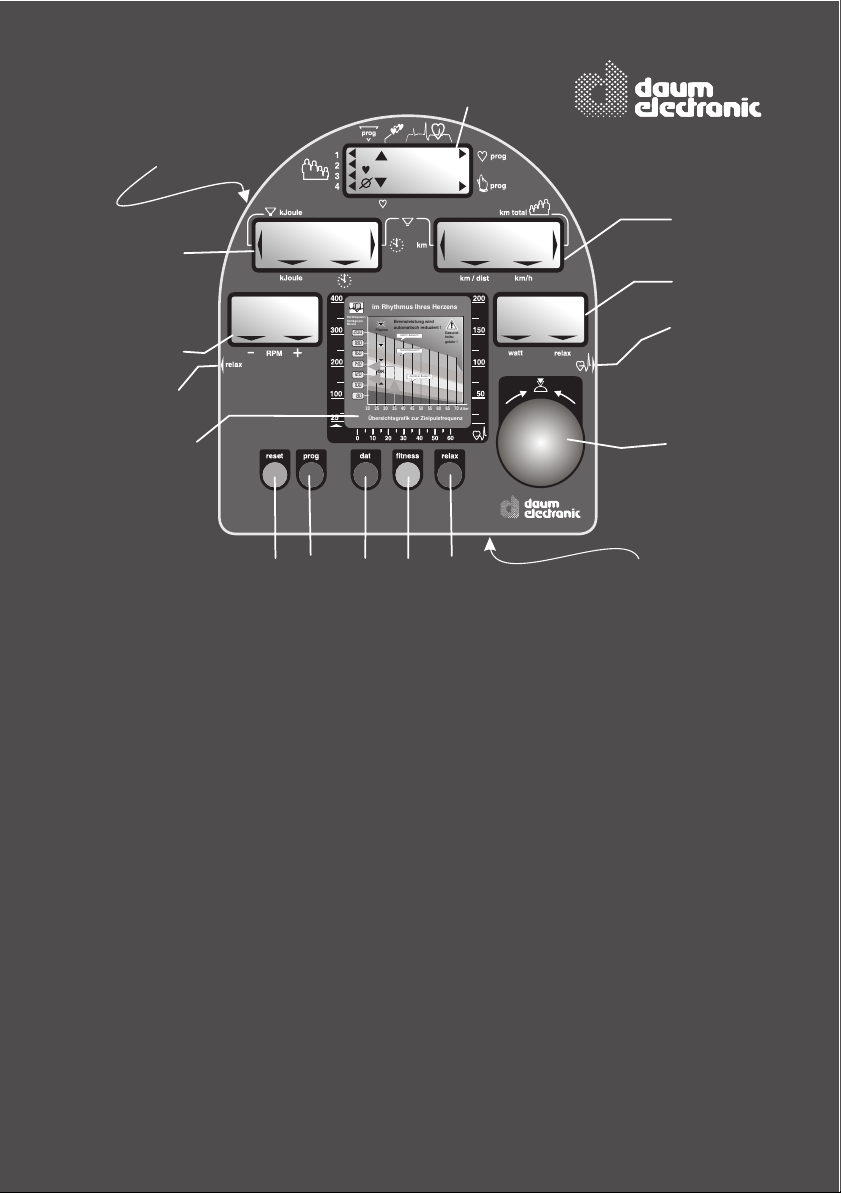
1. LCD-Display
User
Pulse rate
Pulse status
Program identification number
Program display
3. LCD-Display
Pedal speed
(RPM)
4. LCD-Display
Distance
Total kilometers
per user
Distance covered
Average speed
5. LCD-Display
Braking power in Watt
Relax status
2. LCD-Display
Kilojoule burned
Training time
Fitness grade
Limit values for
Kilojoule burned
and training duration
6. Control button
7. Relax sensor connector
8. Pulse sensor /
Ear clip
9. fitness key
10. reset
11. dat
12. prog
13. relax
16. Heart rate diagram
17. PC Interface connector
18. RESET
key
key
key
key
connector
key (recessed)
Page 3
Table of contents
Fold out page
The dashboard/ Overview of the control
elements
Table of contents
Page Page
F. Training programs
FP
A
Programs overview by model
Blank diagrams
Selecting the training program
Cardio Program / C
24 - 27
24
25
26
27
A. Miscellaneous
What is an ergometer?
About this manual
B. Setting up
Switching On/Off
SLP-Mode (Stand by)
C. The dashboard
Control button No. 6
Function keys / input connectors
Window No.1 / Selecting user ID
number and guest user
Window No. 1 / Pulse rate
aerobic pulse zone
Heart pulse rate / aerobic range
Window No. 2 / Time and KJoule
Window No. 3 / RPM
No. 4 / km/h and user km total
Window No. 4 / Distance and km limit
No. 5 / Watt and Relax
Pulse sensor / Cardio Sensor Chest band
PC-interface,
PC-software ergo_win 2002
Manual setting “0”
D. Preparing for training
Setting up personal alarm values
Alarm values Age / Watt / Pulse
Alarm values Time / km / KJoule
Checking settings
E. Training
General recommendations about training
Safety hints about training
Manual training
Fitness test / fitness grade
Recalling training and fitness values
Relaxing / relaxation function
1
2
1 - 13
3
4
5
6
7
8
9
10
11
12
13
14-17
14
15
16
17
18-23
18
19
20
21
22
23
M. Assembling
Installation hints / Miscellaneous
Unpacking / contents
Mounting instructions / mounting the feet
Accessory / “swing-feet”, miscellaneous
Accessory / “swing-feet”, details
/ mounting the handle column
/ mounting the dashboard
/ mounting the saddle
/ mounting the pedals
Fine tuning
W. Maintenance
Cleaning and care
Simple maintenance and service
Replacing the V-belt
Spare parts / overview (cut away drawing)
Spare parts list
Dashboard replacement
T. Technical information
Special accessory / Cardio Sensor Chest band
Technical data
Safety requirements / conformity
S. Index
Index
G. Glossary / Appendix
Glossary
What to do if.....?
§. Warranty conditions
M1-M12
M 1
M 2
M 3
M 4-M5
M 6-M7
M 8-M9
M9-M10
M11-M12
M 11
M 12
W1 - W5
W 1
W 2
W 3
W 4
W 5
T1 - T3
T 1
T 2
T 3
S1 - S2
S1-S2
G1-G3
G1
G2-G3
B
A
A
Page 4
ergo bike
Notes about Software Update
The heart of the dashboard consists of a modern Flash ROM Processor
It allows upgrading all the software related functions, training
programs and fitness tests to the latest release,
even years from now.
The latest software is available for download at the ergo_bike
homepage on Internet and can be transfered to the dashboard
with the ergo_win 2002 PC program
You will find the instructions for this operation in the
that comes with
the software.
“read me” file
Visit us on Internet!
www.daum-electronic.de
Your password for the service area:
“ergo-service”
Page 5
ergo bike
The present instruction manual describes the
This ergometer is specially designed for health and endurance training. High quality manufacturing, easy to see dashboard, ease of use and maintenance all contribute to make this
appliance an ideal training device for sport and fitness purposes. Also note that the complete
equipment and the wide performance range should appeal to sport or fitness conscious
persons of every age group.
What is an ergometer bike?
The ergo_bike was developped and manufactured in accordance with the standard
A DIN EN 957-1/5 (formerly DIN 32932/A), and is therefore suitable for therapeutic purposes.
The ability to prescribe the required power load in Watt beforehand is an essential
feature of an ergometer.
This load is then maintained independently of the speed expressed in revolutions per
minute (within the RPM ranges shown on the graph on page 9), which means it is possible
to train with a load that is considerably independent of the pedaling RPM. This feature
prevents an unwitting exposure to incorrect loads while training.
A full electronically controlled, maintenance free, eddy current break is at the heart of the
ergo_bike. It adjusts the load according to the values determined by the computer to fit the
strictly personal requirements, and allows a continuous load value selection from 25 to
400 Watt.
ergo_bike cardio2002 pc
The ergometer is thus more than a “Home Trainer”, since it can
be used for both sports and therapeutic objectives.
ergo_bike Model
Introduction
About this manual
The cover of this manual contains a foldout page. This greatly simplifies the general
manipulations and the location of the display and control components on the folded out page.
You will find an explanation of the concepts
and expression that are new to you in the
Glossary in the appendix.
An appropriate symbol is used to identify
various important information and remarks.
Please read them carefully.
1
Page 6
Setting up
General information
Switching On / Off
Please read the Notes on Safety (page 19)
before switching the ergo_bike on, and follow
the installation and assembly instructions
(pages M1 - M12).
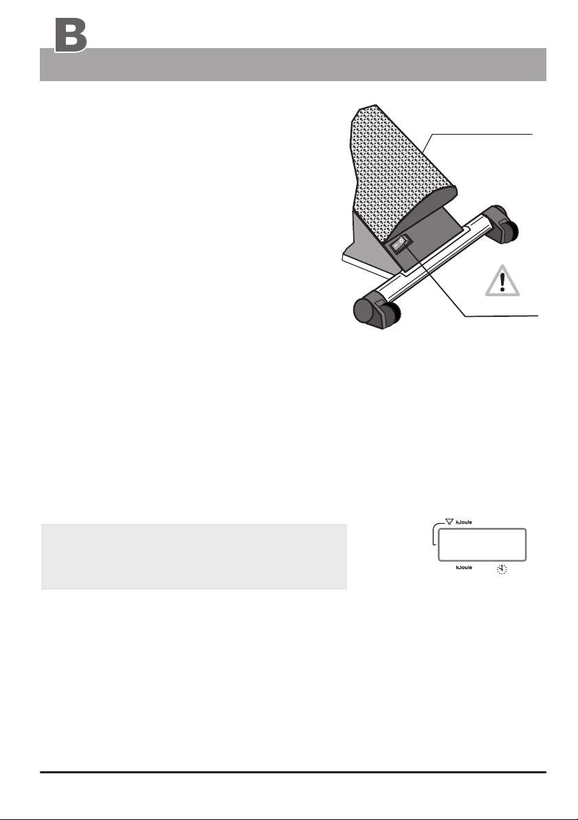
The On/Off switch (power switch) is located
at the back in a rectangular plastic frame on
the rear perforated plate cover.
Upon turning on the power switch (On/Off), the five display windows of the dashboard will
display all the symbols and number segments for about two seconds. This is a self
test on the entire system. run by the computer
The ergo_bike switches automatically to stand by mode if it is left switched on and unused
for about two hours. This is signaled by three beep sounds and ten times blinking of all
the windows, and by the display of “SLP” in window number 2. All other windows are
blanked. This mode is terminated by pressing control button number 6.
The ergo_bike should be switched off by mean of the
On/Off switch or by pulling the power cord plug
from the power outlet.
Always press the Reset key before switching the
device off in order to save the distance covered
in kilometers.
(This does not apply for the values of the “guest” user.)
Please note:
The value of the daily kilometer counter (the wide arrow pointing to Distance) will
always be added to the total kilometer counter (the arrow pointing to User/Km Total),
Displaywindow
“Stand-By mode” ( SLP )
U-shaped
perforated plate
On / Off
(power switch)
Window Nr. 2
)
)
)
SLP
1. if the ergo_bike goes in Stand By mode ( SLP-Mode ).
2. or if the Reset key is pressed,
3. or when another person starts a session and another user identification number
is selected.
Page 7
The Dashboard
Control button No. 6
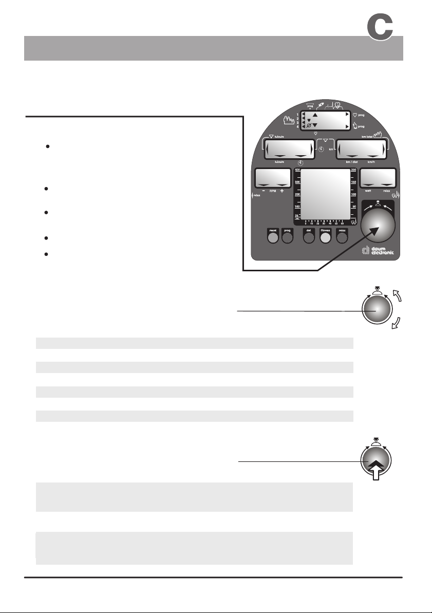
Control button Nr. 6 is the central control element of the ergo_bike.
Two functions in one button!
Turning the control button:
A:
Changes the value displayed in
the active display window
B:
Pressing the control button:
Activates when in the
SLP mode
Stores the value selected by turning
the button
Changing to the next data to enter
Changing the display between Time/km/h
and KJoule/Distance
Instructions to turn the control button are indicated in this manual
the ergo_bike
by this symbol
Entry / Function A :
Age
Pulse
Time
Distance
KJoules
Watts
in one year increment
in one beat
in one minute
in one kilometer
in ten kilojoules
in five watt
increment
increment
)
)
)
88.
88.8
increment
increment
increment
0
OK
188
)
)
)
:
.
8
8
watt
88.
Usage
:
8
.8
88.8
Instructions to press the control button are indicated in this manual
by this symbol
Entry mode / Function B :
when setting personal data
when switching or selecting / in general
To change the display from Time / km/h
to the display of KJoule / Distance
confirming and storing
of the data (page 15)
while training
( see page 8 )
3
Page 8
The Dashboard
Displays / Function keys / Input connectors
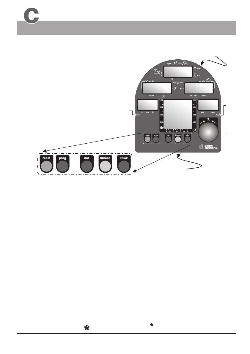
Control elements of the dashboard
1. - 5. LCD Displays
Display windows no. 1 to 5
6. Control button
7. Connector of the relax sensor
used to connect the relax sensor.
(see page 23 / "to relax" )
8. Connector of the pulse sensor
used to connect the pulse sensor /
earclip (see page 11)
13
10
12
9. fitness - key
(has 2 functions)
10. reset - key
11
9
1.
Recalls a fitness mark
2.
Recalls the values of the last training session
Resets the display windows.
7
)
)
)
Window no. 2
Window no. 3
watt
Window no. 1
)
)
)
17
(below)
Window no. 4
Window no. 5
18
(below)
8
6
(see page 21)
(see page 22)
11. dat- key
12. prog - key
13. relax - key
17. Connector
PC-interface
18. RESET - key (recessed)
for the dashboard
computer
(see page G3 )
4
4
what if...?
allows the entry of personal data that will be
used to determine the alarm values to be monitored
during training sessions
This key is used to recall the programmed training
sessions. (see page 26)
Starts the relax program used with the relax
sensor (accessory).
The PC interface (connector) is located on the
underside of the dashboard within the square
opening (see page 12)
The RESET key is located on the underside of the
dashboard, above the protective plate and is intended
to be used in the case of a failure of the internal
computer software.
Page 9
The Dashboard
Window No. 1
User instruction
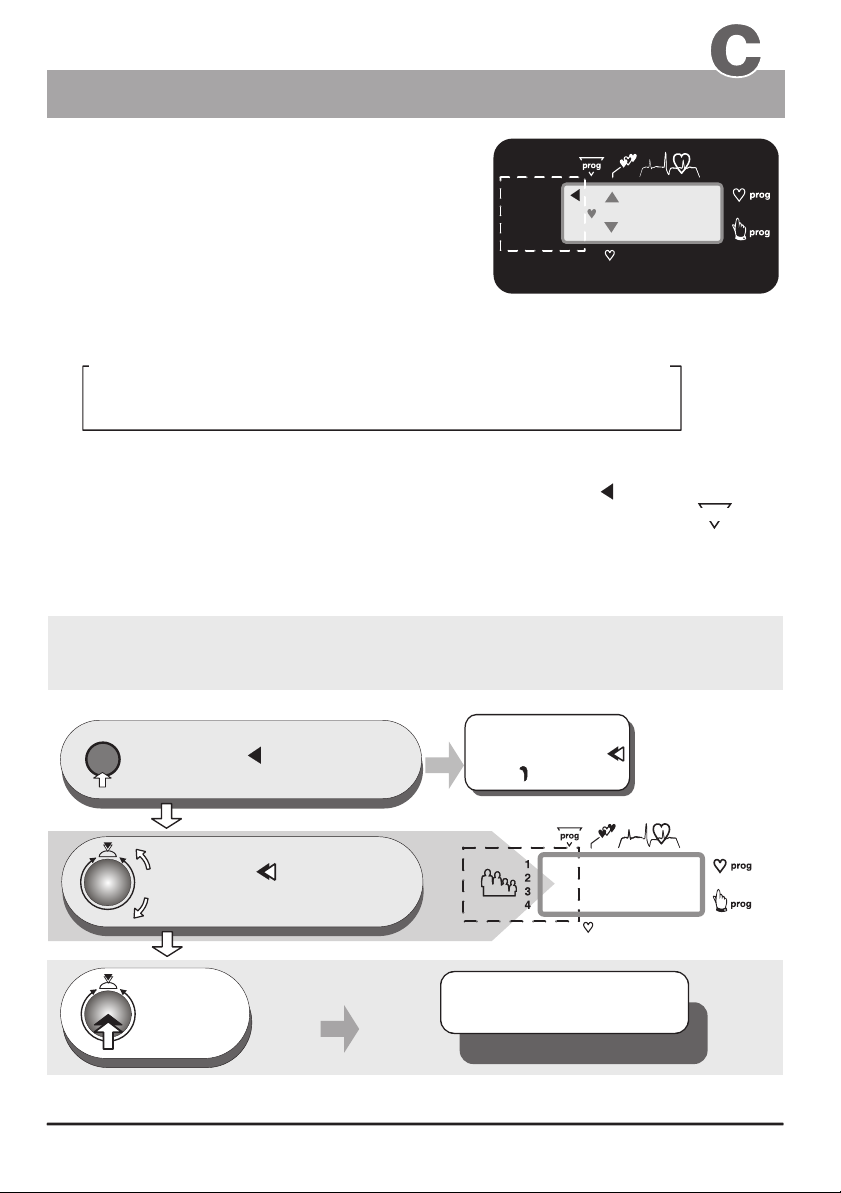
1. Selecting the user
identification number
The ergo_bike computer will record,
store and evaluate the training data of
up to four users separately.
Before using the equipment, you must assign a user number to every user.
The following is an example of a possible number attribution scheme in a family:
Mother Father Daughter
User 1
Guest users, or any persons, whose training data will not be saved, should use
identification number "0". When using this ID number the arrow pointing to
User 1 to 4 will not be displayed. Instead the number "0" is displayed under .
No training data will be saved for the "Guest" user when the ergo_bike
is turned off!
Set up of the User identification number 1 to 4
or Guest 0
User 2 User 3
00
OK
Son
User 4
188
Window 1
prog
reset
1.
3.
press repeatedly until the
user arrow or the "0"
under Prog starts to flash
turn until the flashing
user
2.
arrow points to
the required user number or until
the "0" under prog flashes
press
once
Either
the user arrow
or
00
flashes
Window No. 1
The settings are confirmed
and saved
User 1 - 4 / Guest 0
5
Page 10
The Dashboard
Window No. 1
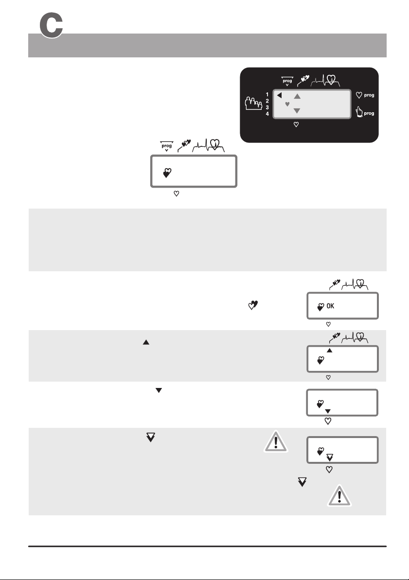
Heart pulse rate
Displaying the pulse rate
The pulse rate or pulse status
is only displayed if the pulse sensor
(ear clip) or the cardio chest band is
connected or when both hand are holding
the pulse sensors (on the handle).
Selected program
a blinking heart
indicates that the pulse
sensor (ear clip) or the
Cardio chest band
is correctly connected
and functioning,
or that both hands are holding the hand pulse sensors.
00
110
actual
pulse rate
Window No. 1
(simplified representation)
00
Displaying the aerobic pulse zone
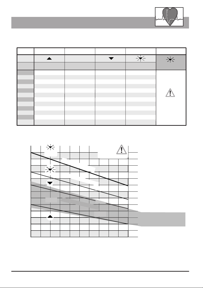
The aerobic zone is a function of the age, it can be determined on the graph
“Target pulse frequency” and the table “target zones of heart frequency” (page 7).
The aerobic pulse zone is only displayed if the user enters his age.
(see page 16 / personal data / alarm levels / age entry )
If the user is training within the aerobic rate zone,
“ OK ” is displayed in window No. 1 (beside the blinking heart ).
OK
120
Window 1
110
The upward pointing arrow indicates
that the user is training below the aerobic zone. To get to the “ OK ” zone
the user must either train longer and/or increase
the braking power in Watt.
The downward pointing arrow indicates
that the user is training above the aerobic pulse rate zone.
To get to the “ OK ” zone the user must reduce
the braking power in Watt.
The downward pointing arrow starts blinking
to indicate that the aerobic rate zone is exceeded by an
excessive margin (the danger-zone is reached),
and the user risks injury by overexercising.
A beep sound combined to the downward blinking arrow
indicates that the user has reached the “alarm zone”.
The ergo_bike starts reducing the braking power automatically
at a rate of 5 Watt per second until the pulse rate of the user
falls into the “danger-zone”.
If the training session is program controlled, and if the training is , the watt setting
will automatically reduced by the same reduction needed to bring the pulse rate to the “danger zone”!
be
blinking arrow!
and
Beep
carried on
199
6
68
160
Page 11
60%-75% 76%-85%
86%-100%
40 - 119 120 - 150 151 - 170
171 - 200
40 - 116 117 - 146 147 - 165
166 - 195
40 - 113 114 - 142 143 - 161
162 - 190
40 - 110 111 - 138 139 - 157
158 - 185
40 - 107 108 - 135 136 - 153
154 - 180
149 - 175
40 - 101 102 - 127 128 - 144
145 - 170
40 - 98 99 - 123 124 - 140
141 - 165
40 - 95 96 - 120 121 - 136
137 - 160
40 - 92 93 - 116 117 - 131
132 - 155
40 - 90 91 - 113 114 - 127
128 - 150
40 - 86 87 - 109 110 - 123 124 - 145
OK
100%
85%
Heart rate frequencies / aerobic zone
Table of target heart rate zone / aerobic zone
Target zone of heat rate frequency to the maximum heart rate
Aerobic Zone
OK
Age
20
25
30
35
40
45 40 - 104 105 - 131 132 - 148
50
55
60
65
70
75
20 0
190
180
170
heart rate
160
150
up to 59%
40 - 119 120 - 150 151 - 170
40 - 116 117 - 146 147 - 165
40 - 113 114 - 142 143 - 161
40 - 110 111 - 138 139 - 157
40 - 107 108 - 135 136 - 153
40 - 101 102 - 127 128 - 144
40 - 98 99 - 123 124 - 140
40 - 95 96 - 120 121 - 136
40 - 92 93 - 116 117 - 131
40 - 90 91 - 113 114 - 127
40 - 86 87 - 109 110 - 123 124 - 145
Overview diagram of the target heart pulse rate
Beep signal
140
130
120
OK
110
100
60%-75% 76%-85%
Alarm Zone
Danger Zone
Aerobic Zone
Health
danger !
100%
85%
75%
60%
90
80
Danger Zone
86%-100%
171 - 200
166 - 195
162 - 190
158 - 185
154 - 180
149 - 175
145 - 170
141 - 165
137 - 160
132 - 155
128 - 150
Alarm Zone
Beep sound
above the
Danger Zone
The braking
power will
automatically
be reduced!
Example
for a person 50 years old
Alarm Zone
Heart rate above 171
Danger Zone
Heart rate 145 - 170
Heart rate 128 - 144
Aerobic Zone
Heart rate 102 - 127
Heart rate 40 - 101
70
20 25 30 3 5 40 45 50 55 60 65 70
If the braking power is reduced by, e.g., 50 Watt in the danger zone, and the value set for the next
program step is, e.g., 150 Watt, then the training will in fact be carried forward with a load
of 100 Watt, as will be shown in the Watt display (window No. 5). The computer makes this
adjustment as a safety measure.
Age
7
Page 12
The Dashboard
Window Nr. 2
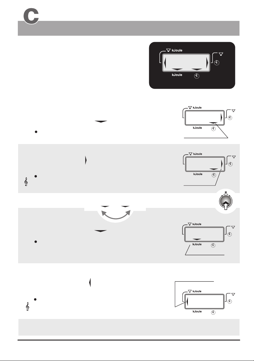
Displays :
the actual training time
the preselected alarm time
the reaching of a time limit (time limit arrow)
the actual kjoule
the preselected kjoule limit
the actual clock time
(when the device is turned on and during training breaks /
see page 10 for setting the time)
Training time and kJoule
)
)
)
:
.
8
88.
Display example
Training duration of 30 minutes
8
)
)
)
1. Training time
When the selection arrow is pointing to the clock symbol:
the elapsed training time is displayed (max. 9 hr 59 min)
(display in minutes/seconds)
1a. Time limit
The time limit arrow is displayed when the preset time
limit is reached.
This arrows indicates that the preset time limit has
been reached or exceeded. Additionally the system
Acoustic signal
Switching between the time and kJoule display using control button Nr. 6
emits an acoustic signal.
kJoule
kJoule
Time Time
2. kJoule
When the selection arrow points to kJoule then:
the energy spend in kJoule
30
Selection arrow
)
)
)
30
time limit arrow
)
)
)
500
)
)
)
Window 2
:
0
0
:
0
0
1 x
)
)
)
)
)
)
)
)
)
is displayed.
Selection arrow
2a. kJoule limit
The kJoule limit arrow is displayed when the preset
kJoule limit is reached.
This arrows indicates that the preset kJoule limit has
been reached or exceeded. Additionally the system
Acoustic signal
(see also pages 14 - 17 / the section on training preparations “personal data / Alarm levels”
or entering the preset values and “Settings verification”)
emits an acoustic signal.
kJoule limit arrow
)
)
)
500
8
)
)
)
Page 13
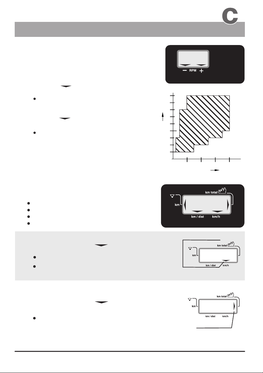
Watt Relax
The Dashboard
Windows No. 3 & No. 4
Displays:
ergo_bike
The is independent of the RPM in the RPM ranges
shown in the diagram to the right. This means that the user
will have to provide an effort corresponding to the displayed
Watt-power .
The arrow points to the minus sign
to indicate that
The user is pedaling too fast
(It is then possible that the displayed power
in Watt is not exactly true).
The arrow points to the plus sign
to indicate that
The user is pedaling too slow
(It is then possible that the displayed power
in Watt is not exactly true).
The power is indicated precision
of about 10% in the RPM ranges delimited
by the arrows
RPM
, within the actual RPM range
in watt to a
+
__
(Pedals revolutions
per minute)
Displays:
km/h
Users / km total
Distance
The reaching of a distance limit
RPM / km/h and km total
57
Window 3
2
1
0
1
1
0
1
0
0
9
0
8 0
0
7
Speed
6
0
0
5
4 0
0
3
0
2 5
1 0
Power
)
)
)
3
2 0
0
4
0
0
Watt
0
0
100
Window 4
1. km/h
When the selection arrow is pointing to km/h
the displays shows:
the actual speed
the average speed.
(when reviewing the values of the last training session)
2. Users / km total
When the selection arrow is pointing to Users / km total
the displays shows:
the total number of kilometers covered by the user or
under the specified user identification number (for
the whole life of the ergo_bike).
Selection arrow
)
)
)
)
)
)
3054
Arrow
25
9
Page 14
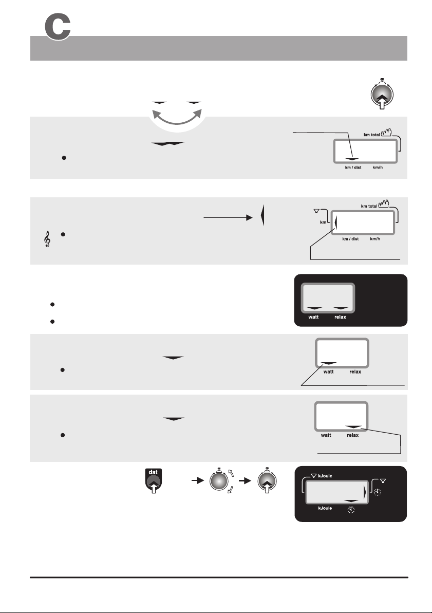
The Dashboard
Windows No. 4, No. 5 and No. 2
Distance/Watt & Relax / Clock Time
Distance and reaching of a distance limit
Switching between the km/h and distance display using button Nr. 6
Distance km/h
3. Distance
When the selection arrow is pointing to the km/dist:
the distance in km covered during the present training session
is displayed.
Distance km/h
Selection arrow
3a. Limit ( km )
The distance limit arrow is displayed when the preset
distance limit is reached.
This arrows indicates that the preset distance limit has
acoustic signal
been reached or exceeded. Additionally the system
emits an acoustic signal.
Displays:
the braking power in Watt
a Relax level
1. Watt
When the selection arrow is pointing to the Watt:
the breaking power in Watt (25 to 400 Watts)
is displayed.
400
1 x
15
)
)
)
60
Distance limit arrow
Window 5
150
Selection arrow
2. Relax
When the selection arrow is pointing to the Relax:
a Relax level, between 0 and 255
is displayed.
Setting the time
Follow the procedure described below to set the correct clock time:
Switch on the ergo_bike while pressing the dat key (Nr. 11), and keep the
dat key pressed for 5 more seconds until numbers are displayed on the
LCD windows. Window Nr. 2 will now display the actual hour setting (and windows Nr. 3 and Nr. 5 will display the software
version number). Adjust the hour setting to the correct clock hour (in 24h format) by turning the control button (6). When
you confirm the hour setting by pressing the control button the system will display the minute value, and the seconds
value successively. Each of which can be set to the correct value by turning the control button, and confirmed by pressing
the same button (6). As soon as the seconds value is confirmed the clock starts running at the set time in normal
operation mode.
10
1010
5 sec
180
Selection arrow
)
)
)
:
8
88
8
)
)
)
Window 2
Page 15
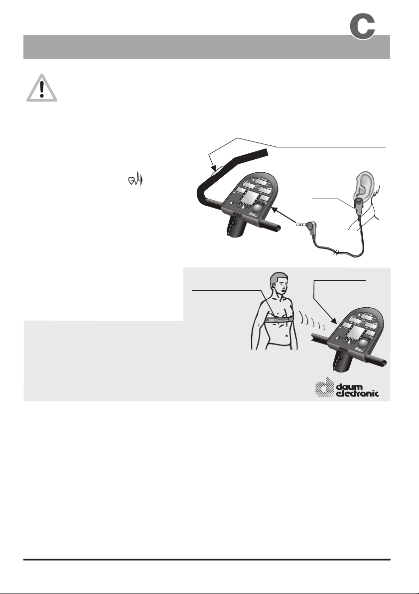
The Dashboard
Pulse sensors / Cardio sensor chest band
The pulse sensor (ear clip) included in the package is an important accessory to
the ergo_bike. You should not start any training session without it, or without the Cardio
sensor chest band available as an option ! The pulse sensors built into the handle can
be used to control or monitor the heart rate over short periods of time.
The ear clip pulse sensor illuminates the ear lobe to measure
the pulse rate. Every heart pulse modulates the light passing through the lobe, and can thus be detected
by an infrared sensor and displayed as heart pulse rate.
Pulse sensor (ear clip)
1.
Insert the connector into the socket no. 8
on the dashboard marked with .
2.
You should rub the ear lobe energetically
with your fingers to stimulate blood circulation.
3.
Attach the pulse sensor (ear clip) to
the ear lobe so that the two contact surfaces
sit entirely on the skin. The heart symbol in
display window 1 starts blinking to
indicate that the ear clip is properly attached
and functional!
Warning!
Strong light sources, like sunlight, halogen
projectors or neon lamps, and also ear piercing
or ear rings, and the intake of beta-blocker
could affect the measurements!
The wireless Cardio sensor chest band
(see the figure to the right), available as an
optional accessory (order number 90 91 015),
permits more precise measurements.
( See page T 1 )
You will find a precise description of the display
and the meaning of the corresponding display
symbols on page 6 (Displaying pulse status).
All ergo_bike ergometers are equipped with a built-in, not visible from the outside, Cardio pulse receiver.
This allows receiving of the pulse rate transmitted by any standard chest band, of the coded and noncoded type. You only need a cardio sensor chest band (see page T1) to achieve wireless heart rate
measurement.
Warning: using two chest bands simultaneously in the same room, either of the coded or noncoded type, to achieve wireless heart rate measurement can lead to the display of a wrong pulse
rate on the dashboard of the ergo_bike.
ergo_bike pulse sensor (ear clip)
Standard accessory (included in the box)
Cardio
sensor
chest band
(with transmitter)
wireless
Cardio sensor chest band
Order Nr. 90 91 015
ergo_bike
Special accessory
Pulse measurement over the hand surface
The sensors built in the handle are used to control and monitor the pulse rate over short periods of time. To
achieve a correct measure you should lay your hands relaxed and loose (not tight) on the electrodes. The
electrical resistance of the skin varies as a consequence of blood pressure variations due to heart pulses.
These variations are measured by the electrodes and displayed as heart rate on the dashboard.
Advice:
If measuring the pulse rate over the hand electrodes gives no results, we recommend using
either the ear clip method or the Cardio sensor chest band. The variations of the electrical
resistance of the skin are so small for some persons that they cannot be used to acquire any
usable results.
Built in hand pulse sensor
left and right of the handle
(standard equipment)
Ear clip
connector
Built-in
Cardio pulse
receiver
available from:
1111
Page 16

The Dashboard
PC Interface
ergo_win 2002
(PC-Software for the communication with the ergo_bike 2002 pc)
The training support provided by the
ergo_win 2002 software was specially
developed for the daum electronic
ergometers of the 2002 pc series.
Comprises:
CD-Rom
Interface cable
Hardware requirements (minimal requirements)
Pentium processor
20 MB free hard disk space
Available serial (Com) port
CD-ROM drive
Keyboard
Operating system: Windows 98 / ME
Features highlights:
Internet capable.
Animated races against oneself, against a computer opponent, against another
ergometer or an internet training partner in real time.
Uncountable number of training programs through exchange and
download possibilities over Internet.
Extremely simplified programming of your own watt and pulse controlled program profiles.
Tour planing for distance controlled training programs.
Extended weight and body fat analysis.
Fully automatic Conconi test / PWC test
Extended training evaluations
Possibility to export all the data to other programs, e.g. Excel.
Extended Coaching functions
User management with individually configurable user interface.
Saving, evaluation and archiving of all the training data.
Provides a wealth of background information on topics of sport medicine
and sport physiology.
Modern user interface.
Simple operation.
Windows 2000 / NT
Order Nr. 90 91 012
Description
Connector
(Underside)
17.
PC Interface
order from:
12
Page 17
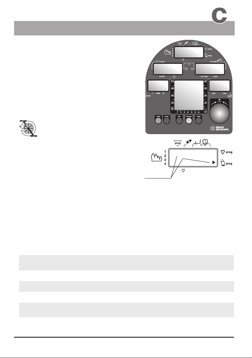
The Dashboard
Display windows
Manual setting “0”
)
)
)
Window no. 2
Basic set up
Window no. 1
)
)
)
Window no. 4
When the ergo_bike is switched on (using
the power switch), or when the “SLP” state
(sleep mode) is canceled using control
button No. 6, it goes into ready state.
You can directly start training without
the need to do any particular setting!
This symbol means start
operating / turning the
pedals.
The following symbols/numbers in display
window no. 1 mean that the ergo_bike is set
Window no. 3
Window no. 6
“the graphical
display is not
available on the
cardio 2002 pc
model”
watt
00
Window no. 5
in manual mode for the indicated user number,
and without the entry of any personal alarm values:
Symbols
Window no. 1
When you start moving the pedals display windows no. 2,
4 and 5 show the actual training values.
The smallest load value for a training with the ergo_bike is 25 Watts.
You can increase or decrease the load in five Watts increments by turning the
control button no. 6.
The pulse frequency will be displayed in window no. 1 when the pulse sensor (ear clip),
or the Cardio Sensor chest band, is connected and functional or when both hands are laid
on the hand pulse sensors on the handle.
Values displayed in the dashboard windows during a training session:
Window no. 1
Window no. 2
Window no. 3
Window no. 4
Window no. 5
Heart pulse rate
(ear clip) or the Cardio Sensor chest band is connected and functional)
(this value is only displayed if the pulse sensor
the elapsed time since the beginning of the training.
RPM the actual speed of the pedals in revolutions per min.
the actual theoretical velocity (km/h)
the actual load setting (in Watt)
and the Relax levels
Window no. 6
graphical representation of the target heart pulse rates
13
Page 18
Preparing for training
Personal settings
Training
1. User identification allocation
Selection of the user ID number User (1 to 4) + Guest
1.1
The computer of the records, saves and evaluates, separately the training
data of up to four users (user identification number 1 - 4).
Additionally, guests or other users, whose training data should not be stored,
can train under user identification number “0”.
ergo_bike
2. Setting up personal data and alarm levels
Training efficiency and control of over and under loading can only be
achieved when the personal data are entered.
The computer of the compares these entries with the actual training
values and evaluates them accordingly.
Possible entries:
Age
Watt upper limit
Upper limit for
heart pulse rate
training duration
distance
Kilojoule spent
About the age entry
Every user should always enter his age when training on the , since it is a significant
figure for the determination of the load requirement and for the corresponding fitness evaluation.
ergo_bike
for example 45 years (from 10 to 99 )
max. 400 Watt (from 25 to 400 Watt )
for example
(if possible, confirm this figure with your physician and do not exceed it)
for example
for example
for example
115 beats (from 100 to 220 )
25 minutes
15 km
350 kJoule
(from 00:00 to 99:99 )
(from 0 to 99 )
(from 0 to 1000 )
ergo_bike
DF 40
DF 400
DF 220
DF 00:00
DF 0
DF 0
About the Watt upper limit
If an upper limit for the load in Watt is entered, then the pulse controlled programs will raise the
load up to this limit. No further increase of the load will occur when the entered limit is reached,
even if the pulse rate did not yet reach the target value. This also applies to all types of programs
(watt, speed, manual, RPM, etc.), as the load in watt will not exceed the value entered for the limit.
About the pulse rate
Users should preferably consult a physician to determine the reasonably
acceptable personal pulse rate.
(see also page 7 / Table and diagram of the target pulse rate)
Rule of thumb to
determine the pulse rate limit:
The warns you when the limit pulse rate is exceeded and the danger
ergo_bike
zone is reached, by displaying a blinking arrow in window no. 1, and by an additional
beep sound when you enter the alarm zone.
(see pages 6 and 7 / aerobic pulse zone and target pulse rate)
for burning fat
for endurance training
160 - ( minus ) age = pulse rate
200 - ( minus ) age = pulse rate
14
Page 19
Preparing for training
Setting up the personal data and alarm levels
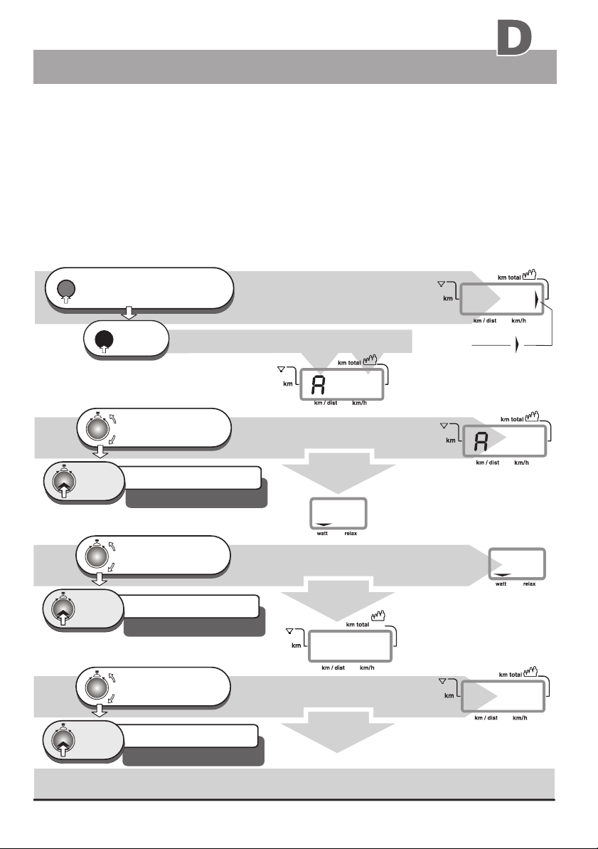
2.0 Data entry and alarm levels set up
The dashboard of the ergo_bike permits the entry of personal alarm levels for pulse rate, upper watt limit,
training time, distance and burned KJoule. When an alarm level is reached during training, a beep signal is
sounded and the corresponding limit arrow is displayed. If you continue training, the beep signal stops, and
only the arrow indicates that the corresponding alarm has been reached.
If the alarm level of the pulse rate is reached or exceeded, the ergo_bike reduces automatically the braking
power in five watts per second increments until the actual pulse rate falls below the alarm level.
The entry of the age is mandatory for the display of the aerobic pulse zone for the user.
(see page 6)
The manual program must be selected before the entry of the data or alarm levels, otherwise
the entry of the pulse rate level will be skipped.
reset
press repeatedly,
until the km total arrow is
1.
displayed in window no. 4 (right side)
dat
Press
2.
1 x
2.1 Age entry
Turn until the age
of the user (e.g. 45)
is correctly displayed
Press
1 x
The setting is confirmed
and saved
e.g. alarm level for the age 45 years
Default level / DF = 40 years
2.2 Watt entry
Turn until the upper Watt limit
is correctly displayed
between 25 and 400 Watt max.
Press
1 x
The setting is confirmed
and saved
e.g. alarm level 200 Watt
Default level / DF = 400 Watt
2.3 Pulse rate entry
turn until the alarm level for
the pulse rate (e. g. 130)
is correctly displayed
Press
1 x
Entering an alarm level of “0” deactivates
the corresponding “alarm”
The setting is confirmed
and saved
e. g. alarm level 130 beats
Default level / DF = 220 beats
window no. 4 displays
window no. 4 displays
)
)
)
0
window no. 4 displays
The set up program goes automatically
to the Watt entry step
window no. 5 displays, e. g.
400
window no. 5 displays
The set up program goes automatically
to the pulse rate entry step
)
)
)
P
window no. 4 displays
The set up program goes automatically
to the time entry step
0
window no. 4
)
)
)
0
arrow
!
0km only the first time
the unit is turned on
window no. 4
)
)
)
45
200
window no. 4
)
)
)
130
P
Continuation
2.4 Time entry
15
Page 20
Preparing for training
Personal settings
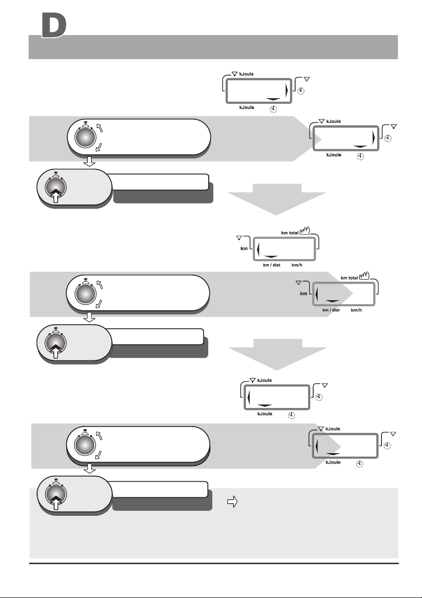
2.4 Time entry
turn, until the required
training duration (e.g. 25 min.)
is correctly displayed
Press
1 x
The setting is confirmed
and saved
e. g. Time alarme level 25:00 Min
Default level / DF = 00:00 Min
2.5 Distance entry
turn, until the required length
for the training circuit
(e.g. 15 km) is displayed
press
1 x
The setting is confirmed
and saved
e. g. Distance alarm level 15km
Defaul level / DF = 0 km
Training
)
)
)
:
0
00
0
Window no. 2
)
)
)
2.2 Pulse rate entry
)
)
)
25
The set up program goes
automatically to the distance
entry step
)
)
)
0
)
)
)
Window no. 4
The set up program goes
automatically to the kJoule
entry step
)
)
)
)
)
)
Continued
from
:
0
0
15
)
)
)
2.6 kJoule entry
Turn until the value of the
required value of the
burning
(e.g. 350) is displayed
press
1 x
The alarm values entered remain stored when the is turned off. If you should need to
change one or more of the alarm values, you can overwrite the corresponding pld alarm value with
the new one (using the same procedure described above).
The setting is confirmed
and saved
e. g. alarm level 350 kJoule
Defaul level / DF = 0 kJoule
kJoule
Window no. 2
steps to window No. 4
in setting verification mode
ergo_bike
A
Automatic
0
)
)
)
350
16
)
)
)
Page 21
Preparing for training
Setting verifications
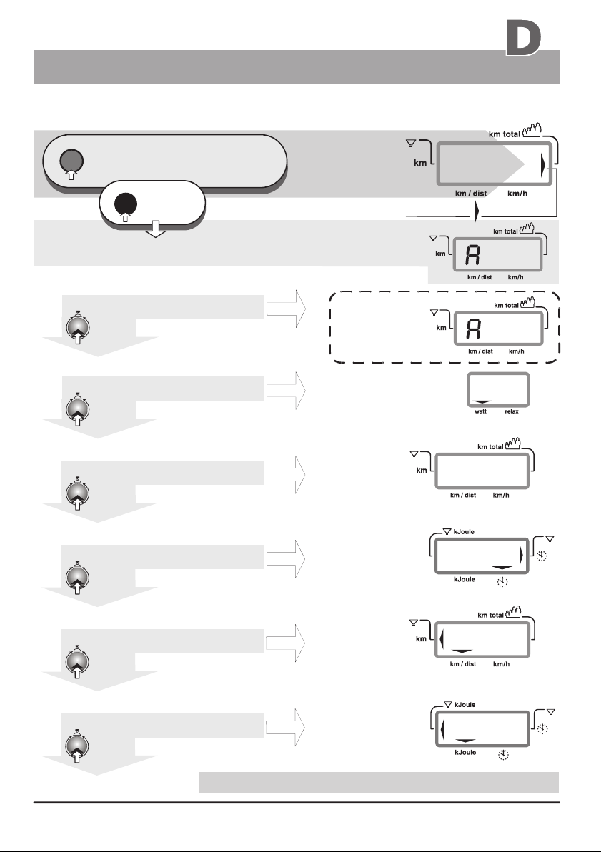
3.0 Settings verification (alarm levels)
reset
press repeatedly,
until the km total arrow is
1.
displayed in window no. 4 (right side)
dat
press
2.
1 x
Window no. 4 displays the last alarm level set up
(corresponding to example 2.1 = 45 years)
3.1 age entryverifying the
Verify the setting
confirm
press
1 x
or eventually ...? change
3.2 Watt verifying the entry
Verify the setting
confirm
press
1 x
or eventually ...? change
3.3 pulse rate entryverifying the
Verify the setting
confirm
press
1 x
or eventually ...? change
3.4 Time entryverifying the
Verify the setting
confirm
press
1 x
or eventually ...? change
3.5 Distance entryverifying the
Verify the setting
confirm
press
1 x
or eventually ...? change
3.6 kJoule entryverifying the
Verify the setting
confirm
press
1 x
The set up program returns to output display mode
or eventually ...? change
A
Automatic
Window no. 4
Alarm level setting
made at 2.1
Example of
a modification
Alarm level setting
made at 2.2
Alarm level setting
made at 2.3
Alarm level setting
made at 2.4
Alarm level setting
made at 2.5
Alarm level setting
made at 2.6
)
)
)
Arrow pointing
!
A 45
Window no. 5
)
)
)
Window no. 4
Window no. 2
)
)
)
Window no. 4
Window no. 2
)
)
)
)
)
)
P
)
)
)
25
)
)
)
Training
0
to km total
45
32
200
130
:
0
0
15
350
)
)
)
)
)
)
17
Page 22
Training
Introduction
The ergo_bike makes it possible to define and control the exercise sequence yourself. It is thus
possible to adapt constantly the training plan to the capacities of the user. This device is suitable for
therapeutic use. It does not meet the requirements of medical and diagnostic usage
(in medical clinics).
This ergometer has been essentially designed for endurance, agility and physical condition training and
for strengthening the heart and circulation systems and to help develop the muscular mass. The goal of
such training is to increase the capacity of the body to absorb oxygen, and to improve its overall flexibility.
The inclusion of the pulse rate in the parameters used to control the loading enables training in
the efficient aerobic zone.
Being in the aerobic zone means the muscles loading is at the exact level where they can be adequately
supplied with oxygen without overproduction of lactic acid (aching muscles). Therefore, the ergometer
bike is also a great value for sports medicine and physical education.
The fact that the training effort can be finely measured, gives you
the possibility to carry out physical stress tests to get information
on your physical condition. You can thus identify early any heart
and circulation problems and, with the help of a physician, set up
a special endurance training plan to treat them.
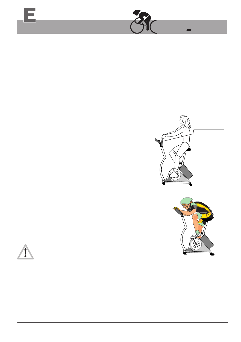
A confortable and relaxed sitting posture are of great
significance for the efficiency and the benefit of the
ergo_bike. You should not be tensed up while training.
You should wear loose sport clothes so that you don't
get into sweat too easily and are not constricted. Your
back should be straight (as opposed to the racing
posture, see fig. B), and your legs should still be
slightly bent at the lower pedal position. This posture
is illustrated in figure A. You should adjust the handlebar
and saddle height and inclination to suit your needs.
Sport physicians recommend preparing for training with relaxing
exercises, which can be followed by some stretching. exercises.
Any user who does not feel completely fit, considering either
the health or physical aptitude aspect, should prepare himself before
training with the ergometer, or consult a physician if in doubt
ergo bike
Handle in
position!
Fig. A
Training properly
Training properly means to load the body reasonably,
in order to achieve the required fitness level
and to retain it.
A lower load will not bring the required effect, while overloading can be dangerous!
Training units per week
Generally speaking, training twice a week will help retain your physical condition.
To improve your fitness level you must train at least three or four times per week.
You should consult a physician before increasing the number of weekly training units,
to avoid overloading yourself.
18
18
Fig. B
Page 23
Training
Safety information
Information about personal safety
The ergo_bike ergometer is intended for use by adults. It is not a toy.
Children should only be allowed to train with the ergometer under
adult supervision.
Persons suffering from any of the following diseases should consult their family physician or
a specialist before starting training with the ergo_bike.
Heart disorders like angina pectoris, coronary thrombosis, stenosis, high blood pressure
Diabetes
Respiratory disorders like asthma, chronic bronchitis, etc.
Rheumatism
Gout
or any other disease or illness
You should never train when you feel ill or weak (your own body is often the best sensor).
If a user starts feeling ill or weak, he or she must immediately stop the training, relax
and consult a physician.
Persons who are not used to exercise, and are not used to providing a physical effort
regularly must start with an easy training program, and then increase the load very gradually.
Persons with declared health problems must evaluate their personal risks with the help
of their family physician.
You should never use the ergo_bike to find out your maximum degree of physical
endurance by setting the load in Watt and your pulse rate too high.
This can have serious consequences on your health!!!
The ergo_bike is suitable for therapeutic utilization
(it complies with Class A DIN EN 957-1/5 / formerly DIN 32932/A ).
(It does not meet the requirements for medical diagnosis usage in medical clinics.)
Note
You will find more information about training for sport and health in the pocket book
“Training with the bike ergometer” Improvement of health and fitness as training target
with the ergo_bike.
Order from: daum electronic GmbH, Flugplatzstr. 100 D-90768 Fürth
Fax ++49 (0) 911 75 37 14
Training conditions
You should pay attention to providing good training conditions, this includes choosing the
training room and installation place. Makeshift installation places do not incite to training!
19
Page 24
Training
Manual training
ergo bike
Miscellaneous about manual training
Under training program “0” (manual) you can adjust the pedaling effort (braking
power) between 25 and 400 Watts by turning the control button No. 6, and also
change it during the training in 5 Watt increment to adjust the load to your
personal requirements.
Preparing for training
Select the user identification number (1 to 4) or guest
Set personal data and alarm levels (pages 14 to 16)
Where you determine
a) Timed training (Enter an exercise duration as alarm level)
b) Distance related training (Enter a training distance / km as alarm level)
c) Kilojoules related training (Enter a KJoule value as alarm level)
(page 5)
Health and rehabilitation training
This type of training should be performed only according to the time and effort prescriptions
of a physician or therapist.
Training examples
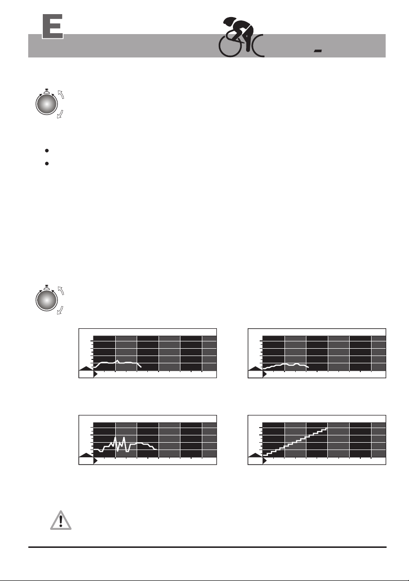
The effort settings in Watt can be freely varied according to the performance diagram
selected to “run” and be set according to the represented time intervals.
Beginner program
Beginners Training 2
4
00
0
30
0
2
0
100
0
10 20 30 40 50
23 min / 130 Watt max.
for untrained men up to 70 years of age
15
min
Active sports persons
WATT
Matterhorn
4
00
0
30
0
2
0
100
0
10 20 30 40 50
30 min / 270 Watt max.
for trained users
About the fitness test 25 Watt / WHO-Standard
This exercise takes the user to his/her performance limits. You should only take it after consulting
a physician, and you should interrupt the test immediately at the first sign of discomfort or pain!
10
min
Active Sport Lady
Active Sport LadyWATTWATT
4
00
0
30
0
2
0
100
0
10 20 30 40 50
22 min / 90 Watt max.
for untrained women up to 60 years
Fitness test of the WHO
WATT Fitness test of the WHO
4
00
0
30
0
2
0
100
0
10 20 30 40 50
Fitness test 25 Watt / WHO-Standard
32 Min. / 25 - 400 Watt
(increased in 25 Watts increments at
two minutes interval)
13
min
1
min
20
Page 25
Training
Fitness mark / fitness evaluation
Fitness mark
The can carry out an evaluation your fitness. The measurement principle is based on the
ergo_bike
fact that the pulse rate falls faster within the first minute following the training session for healthy, welltrained users than for healthy, less trained users.
If the user presses the Fitness key during a training session, the present training will be interrupted and
the load will be lowered to 25 Watt within 3 to 4 sec. The graphical screen will display the message
“Fitness mark evaluation”. The drop in pulse rate within 60sec will be measured (see window no. 2)
and the mark computed according to the following scheme and displayed:
The fitness mark F1 is awarded for a pulse rate drop of more than 25.0% within 60 sec
The fitness mark F2 is awarded for a pulse rate drop of 20.0% to 24.9% within 60 sec
The fitness mark F3 is awarded for a pulse rate drop of 16.0% to 19.9% within 60 sec
The fitness mark F4 is awarded for a pulse rate drop of 12.0% to 15.9% within 60 sec
The fitness mark F5 is awarded for a pulse rate drop of 8.0% to 11.9% within 60 sec
The fitness mark F6 is awarded when the pulse rate drop is less than 8% within 60 sec
The mark of “F0” is awarded if no usable result can be measured.
The training program resumes at the actual position after the evaluation process. The load in Watt is
raised within 3 to 4 seconds to its value just before the evaluation and the training can be continued.
A fitness evaluation is not possible after the training session is finished.
Fitness evaluation process
A pulse measuring device (pulse sensor / ear clip or the cardio sensor chest band) must be
connected and functional during the whole fitness evaluation process.
The measuring process takes one minute and its progress is displayed.
1. Train at least 15 minutes in the OK-area (see page 6).
Continue pedalling “loosely” at the load of 25 Watt during the 60 sec measurement process.
2.
3.
fitness
3.
4.
5.
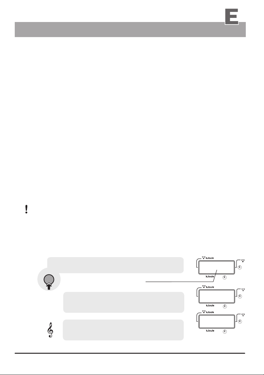
Press the fitness key only when the two dots in
display window no. 2 are blinking.
The two dots blink during
the training!
Window No. 2 displays an “F”,
and a timer from 1 to 60 seconds during
the .measurement process
After one minute window no 2 displays
the F mark and the system plays a small melody.
Example of the display
of fitness mark 2
)
)
)
15
)
)
)
F
)
)
)
F
Window no. 2
:
0
0
:
6
0
2
21
)
)
)
)
)
)
)
)
)
Page 26
Training
Recalling training values
Recalling the last training values after training
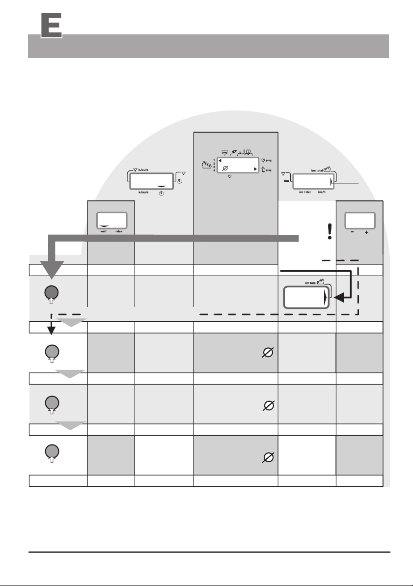
You can recall the values of the last training session with the ergo_bike.
You can do this during actual training or after the training session.
Recalling the training values
is not possible when the user
is set to “0”
(guest user)!
Window 2
)
)
)
window 3
reset
A
1.
press
fitness
2.
fitness
3.
fitness
4.
1 x
press
1 x
press
1 x
press
1 x
press the fitness key only (B)
The display shows: The display shows: The display shows: The display shows:
B
the training time
C
The display shows:
D
kJoule
burned
Dashboard displays
Window 1
)
)
)
00
The display shows:
the selected user
evtl. a program number
evtl. a program arrow
average symbol
average pulse rate the distance
The display shows: The display shows: The display shows:
average symbol
maximum pulse rate
The display shows: The display shows:
average symbol
Fitness mark
)
)
)
If in
Window no. 4
the arrow is
not
pointing to
Users / km total
... or if
the arrow
is displayed
Users /
km total
the average
velocity
The display shows:
the average
velocity
Description
Window 4
no arrow
displayed?
Window 5
the average
RPM
the average
RPM
the average
RPM
A
RPM
If you wish to consult the last values during the training, skip the step of pressing the Reset key
(Function A).
The display of the values of the last training is terminated when you move the pedals or press
the Reset key.
22
Page 27
Training
Relaxing
The relaxation function
The relaxation function is a Biofeedback-process that is carried out by measuring the electrical
resistance of the skin. The measured values are indicated by means of optical and audio signals.
Biofeedback is thus the translation into perceptible signals of physiological processes occurring in
our body, which our senses can barely, or not at all, perceive.
The relaxation function is the ergo_bike's way of helping you relax and eliminate stress.
You should use this option particularly after a physical endurance training.
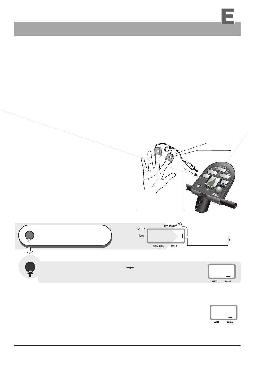
Connecting the relaxation sensor
1.
Take the velcro bands of the fingers' sensor out of the package and open them.
Place the open tape on one of your fingertip (e.g. index finger). Make sure there is good
2.
contact between the silver buttons and your skin. The wires from the tape should lead
away from the back of your hand.
3.
Put down the side of the velcro tape with the
sensor button on your finger and wrap the
other side around it and press it firmly in place.
Wrap the other tape around your middle finger
4.
in the same fashion.
5.
Plug the connector of the relaxation sensor into the
“Relax” input socket no. 7 on the dashboard.
Velcro tape
Sensor button
Relaxing
Relax program / process description
reset
Press repeatedly,
until Window no. 4 (right side) displays
1.
the arrow pointing to km total
relax
2.
3.
personal
relaxing
process
The wide down pointing arrow in Window no. 5
switches from Watt to Relax.
A value is displayed, which starts at 199.
The displayed value drops gradually as you relax
after training.
The Relax-value can drop all the way to almost zero.
The user should therefor contribute to his/her relaxing
and avoid any other stress. You can support this process
by getting off the device and sit in a relaxed position, or
lay down close to the ergo_bike and calm down.
The complete relaxing process is divided into 25 levels. A short
beep sound signals when each level is achieved. The successive
beeps are each lower in tonality.
Relax sensor
connector no. 7
)
)
)
Window no. 4
0
Arrow pointing
to km total
!
199
Window no. 5
0
23
Page 28
Training programs
Programs overview by model
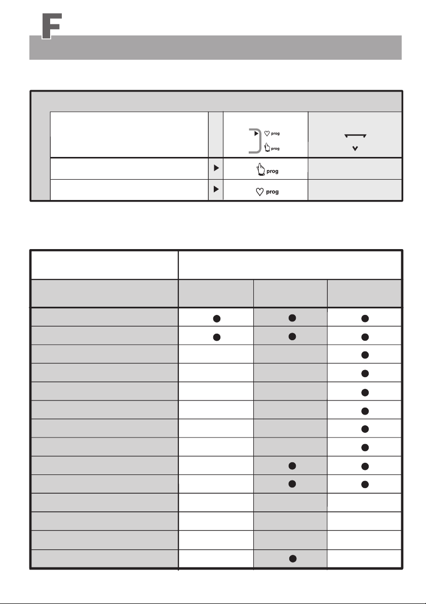
The following table lists the programs installed in the ergo_bike “cardio2002 pc”
The programs are identified by the following symbols in the dashboard display windows.
Setting
Overview / Program types
Arrow
1.
Manual program /
Cardio program /
2.
It is possible to upgrade the system with new training programs. To do this, the dashboard must be
removed (see page W5) and sent to daum electronic gmbh, Fürth.
(More detailled information and the upgrade price can be obtained by fax at number 0911 / 9 75 36 28)
Programs overview
ergo_bike programs
Manual program
Cardio program
Individual / P ( IL 60 )
Individual / P ( IL 240 )
Individual / P ( IP 60 )
Individual / P ( IP 240 )
Individual / P ( Ir 60 )
Individual / P ( Ir 240 )
(watt controlled)
0
(pulse controlled)
C
Manual /
Cardio /
Watt
Watt
Pulse
Pulse
km/h
km/h
ergo_bike models
cardio2002 pc
0
C
fitness2002 pc
Setting
prog
0
C
(comparative)
vita2002 pc
de luxe
Intensification prog. / L
RPM program / A
Fixed programs watt controlled
Fixed programs pulse controlled
Cool-Down programs
Individual / P ( IL 30 )
24
RPM
RPM
Watt
No. 1 - 19
No. 1 - 19
No. 29 - 38
No. 42 - 44
Page 29
Training programs
Blank diagrams
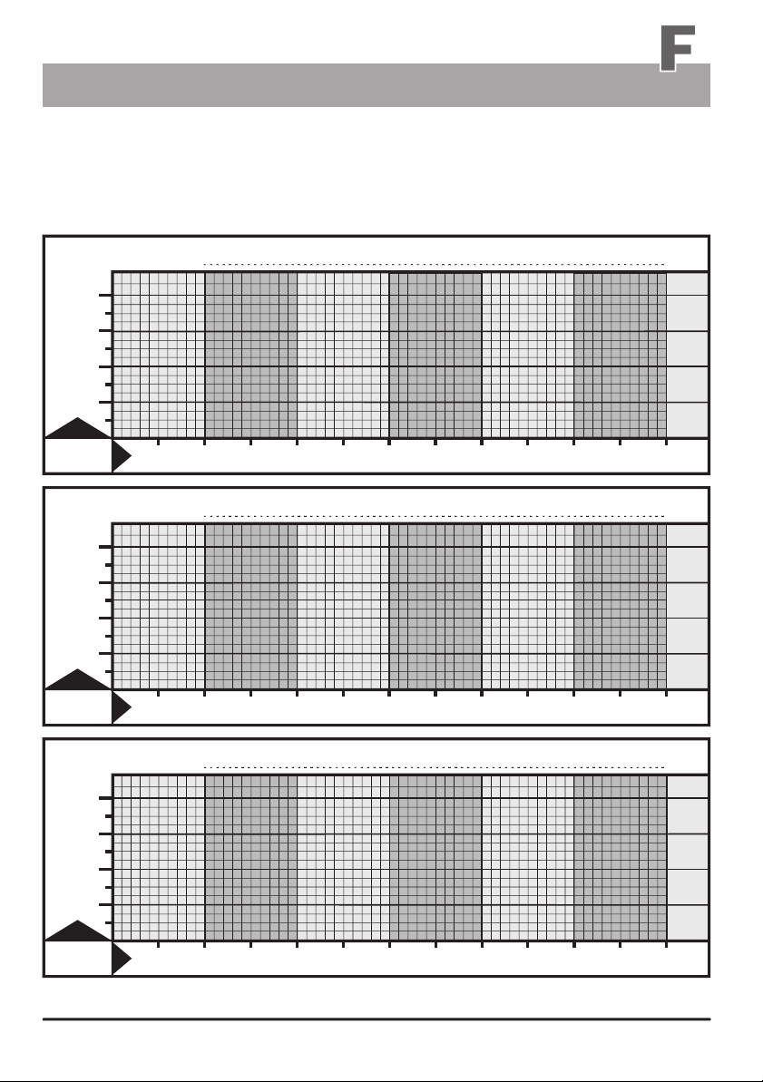
The Watt program allows the design of personal training sessions in one minute step and 5 Watt levels.
Copy the following blank diagrams and use the copies to represent the individual training sessions in the
form of a performance curve. This can then be used for archiving the personal training programs.
WATT
40
0
300
200
100
0
min
10 20 30 40 50 60
WATT
40
0
300
200
100
WATT
40
0
300
200
100
0
0
min
min
10
10
20
20
30
30
40
40
50
50
60
60
25
Page 30
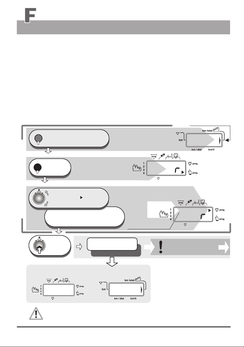
Training programs
Programs selection
Training Programs selection
Several training programs are stored in the ergo_bike that help automate training sessions.
When running a program, the load will be adjusted, increased or decreased, depending on the
distance, pulse rate or even velocity, according to the watt values prescribed by that particular
program.
The table on page 24 lists the available programs on each ergo_bike model respectively.
Use only display windows no. 1 to 5 for setting and functions description.
Users / km total
)
)
reset
Press repeatedly,
until the arrow pointing to km total
1.
appears in window no. 4 (right side)
prog
press
2.
1 x
window no. 1 displays
a big Pr
Window no. 4 displays
00
)
P
0
Turn until the
Program arrow points to
3.
the selected program on the side
Standard Selection Steps 1 to 3
or the number or short description
of the selected program is displayed
under Prog
press
4.
1 x
The setting is confirmed
and saved
e. g. Program .......
e.g. windows no. 1 and no. 4 display
CC
The selected program will be only saved in connection with the user identification numbers
1 to 4 when the device is turned off.
26
Window no. 1
CC
P
e.g. Cardio program
only for the Cardio / C
Program
)
)
)
8
Page 31
Training programs
Cardio Program / C
This program is specially developed for efficient heart and blood circulation training.
The braking power (Watt) is automatically regulated, so that the pulse rate set by the user
remains constant during the whole training session.
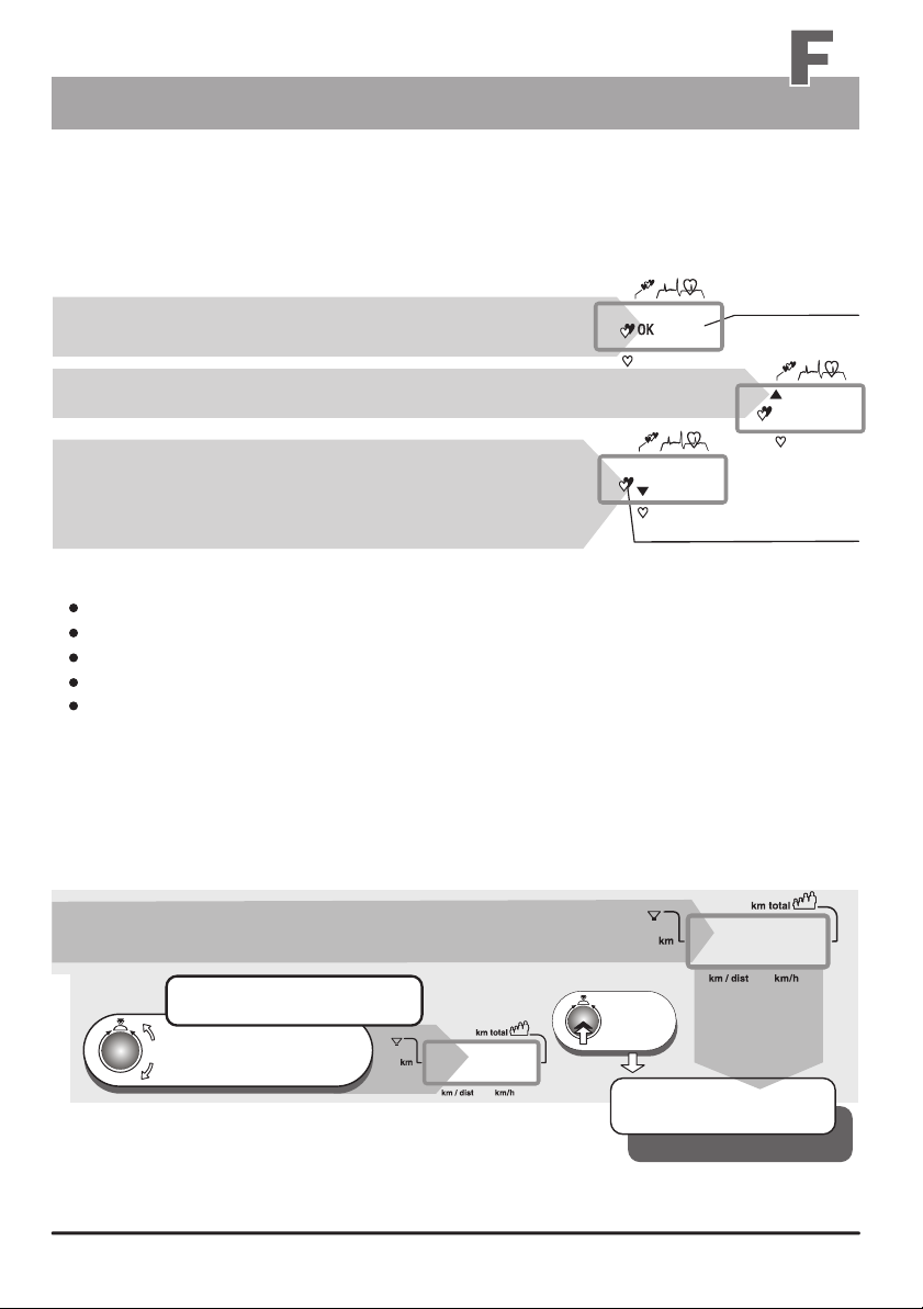
Select the program (see page 26) “Standard selection steps”
e.g. preset
The OK display indicates that the pulse rate does not exceed
the preselected pulse rate by more than five pulses.
110
cardio pulse rate
The up pointing arrow indicates that the pulse rate is lower
than the preselected cardio rate.
The down pointing arrow indicates that the pulse rate is
higher than the preselected pulse rate by more than five
pulses. In this case the braking power (Watt) will be reduced
by 10 Watt / 15 seconds continually until the preselected
cardio pulse rate is again achieved.
Running the Cardio-Program C
Select the user identification number (see page 5)
Put on the pulse sensor (see page 11)
Select the Cardio-Program C (see page 26)
Set the required heart pulse rate, then press control button No. 6
Start pedaling
The selected heart pulse rate remains stored even after the ergo_bike is switched off.
The braking power (Watt) will be automatically raised until the target heart pulse rate is reached. Well-
trained users have the possibility to reduce the time needed to reach the target pulse rate by turning
control button No. 6 to raise the braking power (Watt).
Window no. 5 first displays 25 Watt, which are then raised by five Watts every 15 seconds untilthe
required heart pulse rate is reached. Then the braking power (Watt) is automatically regulated to
the value that keeps the pulse rate at the selected value.
Window no. 4 displays a “P” and a number between
80 and 199, the prescribed training pulse rate.
If you want to change this value
)
)
Turn until the target heart pulse
rate required or recommended
by a physician is displayed
We recommend the use of the possibility of entering alarm
levels (see pages 15 and 16)! With the exception of the
entry of a pulse rate alarm level (for heart pulse rate programs).
The heart pulse rate should never be set too high in order to avoid overloads (see page 7). When in
doubt you should always consult a physician or therapist.
)
P
110
window no. 1
116
The blinking heart indicates
that the pulse sensor (ear clip)
or the Cardio sensor chest
band is installed
and operating.
)
)
)
P
4.
1 x
press
The setting is confirmed
and stored
Window no. 4
value is O.K.
e. g. program no. C
98
80
the
27
Page 32
Assembly
Installation Hints
Miscellaneous
Install the ergo_bike on a level floor. The manufacturer will not be held responsible for any damage
done to the floor. We thus recommend installing the device on a protective base.
The ergo_bike is not intended for use in damp rooms. Rust could develop, which would damage
parts of the device and impair both the operating functions and the safety features.
The ergo_bike uses a mains voltage of 220 to 240 Volt, 50/60 Hz and has a power consumption of
50 Watt. The power supply you wish to use must fulfill these requirements!
Any defect or deficiency of the device that could have an impact on the safety should absolutely be corrected immediately. Defective or broken parts should be replaced immediately (see
spare parts list on pages W3/W4). In the case of a defect, the device should not be used until
it is completely repaired.
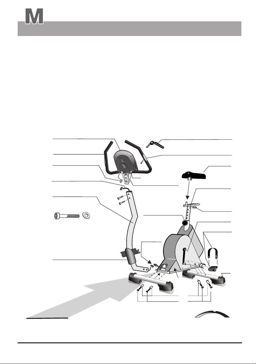
Dashboard 4.1
(pre-installed)
Handle 7
Hand pulse cable 7b
(white connector / HS )
Dashboard cable 3
(black connector / CS )
Handle support column 2
F / G
F / 2x
Handle column
fastening screws
Dashboard support 6
Attention !!
G / 2x
Carefully
le suppor
hand
insert th
t column !!
Tensing lever 6a
(for the dashboard clamp)
Hand pulse sensors 7a
Saddle 13
H/J
Clamp 8.1
toggle button 12a
Saddle
support 12
with horizontal
adjustment guide
toggle button 12d
device body 1
Pedal 16/17
wirh
Connector
SF
straps
16a/17a
Roller
F/G
e
B
SF
A
g
n
i
e
w
f
SF = “swing-feet”
s
f
e
c
t
The cable of the handle support column must be driven into the column (after plugging the
connector) before inserting the column into the frame. Otherwise, the cable could be crushed,
which could lead to malfunctions of the ergo_bike!
M 1
M 1
Page 33
Assembly
Unpacking / Contents
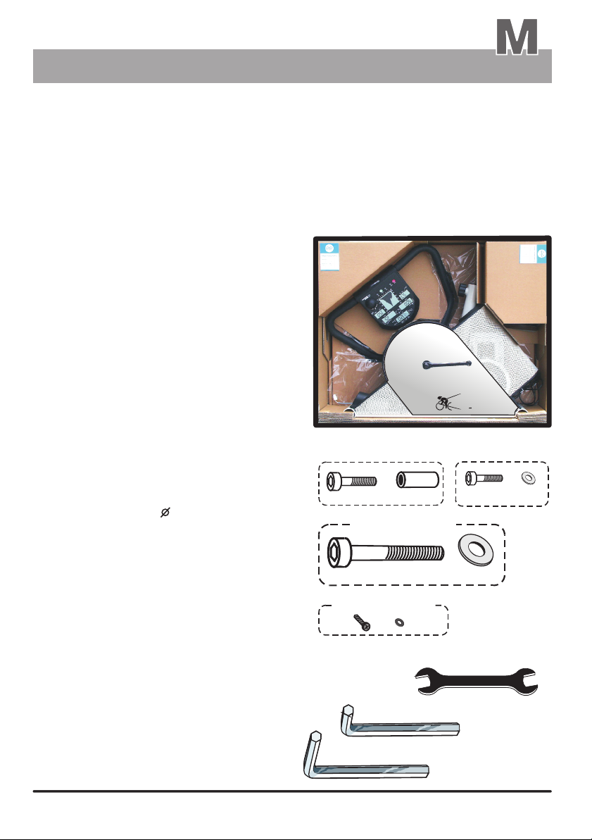
Contents of the box
The package contains all the parts necessary for installing and using the ergo_bike, including
Festprogramme / pulsgesteuert
the required tools.
Please make sure no parts are missing!
When unpacking the parts, make sure you remove them carefully from the cardboard box,
not only to avoid personal injuries, but also to avoid any damage or loss of parts.
The package contains:
1 ergo_bike main device
1 Saddle
1 Dashboard with protection plate, clamp
and handle with hand pulse sensors
1 Dashboard support
1 Handle column with integrated dashboard cable
(cable connecting the dashboard to the main device)
2 device feet
4 “swing feet” set
2 Pedals
2 Pedal straps
1 Saddle support
1 Tensing lever
1 trapezoidal perforated plate cover (left)
Hardware:
4 Recessed head screws M 8x50 ( A )
4 spacer sleeves 12 x 32 mm ( B )
2 Recessed head screws M8 x 40 ( C )
2 DIN 125 8.4 ( D )Washer
2 Recessed head screws M 10x70 ( F )
2 DIN 125 10.5 ( G )Washers
2 S sw DIN 7971 2.9x13 crews
2 DIN 125 3.2 ( J )Washers
Tools
1 Wrench 14/15 mm
1 Allen wrench SW 5
1 Allen wrench SW 6
1 Allen wrench SW 8
Accessories
1 Pulse sensor earclip
1 Relaxation sensor
1 Software-update-cable
1 User manual
(with mounted
pedal cranks)
( H )
ergo_bike
Dashboard support
H / 2x
contents of the box
frame of the feet
A / 4x
Handle column
F / 2x
B / 4x
J / 2x
G / 2x
14
SW 8
ergo bike
C / 2x
SW 6
Clamp
D / 2x
15
M 2
M 2
Page 34
Assembly
Installation hints
Short Description
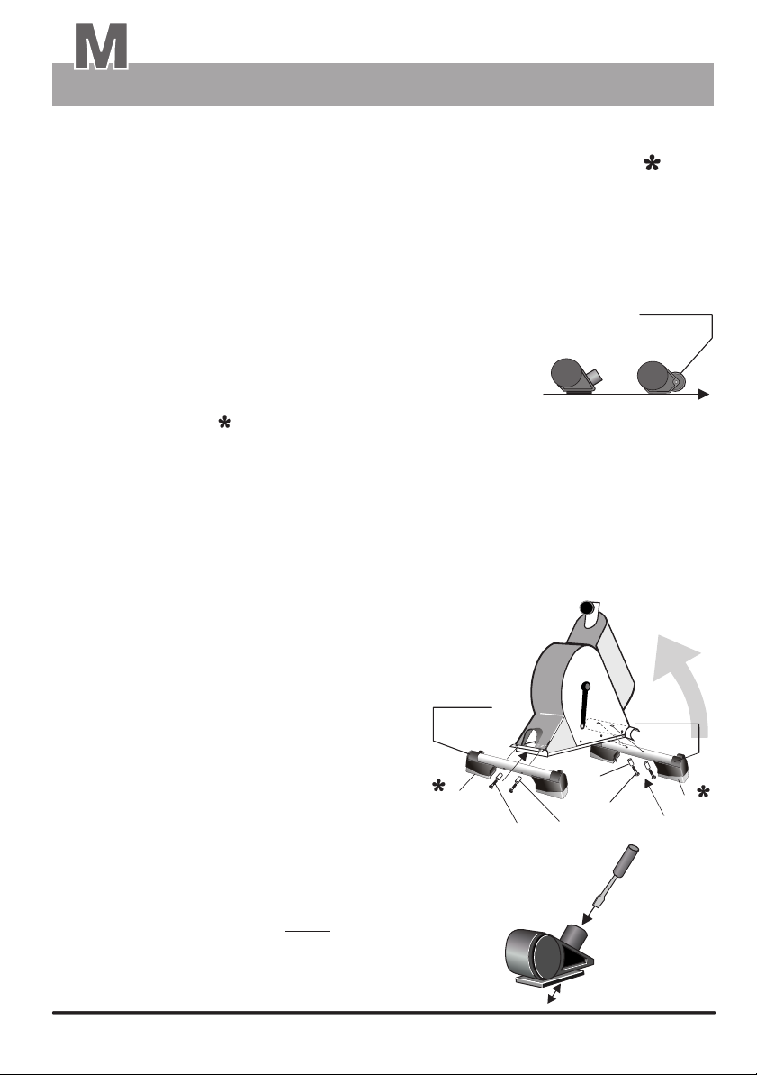
1. Assembling instructions / Installing the feet
Required hardware: 4 x recessed head screws A
4 x spacer sleeves B
Required tool:
Pull the main device from the package and put it down in an upright position.
1.1
Please take the type of foot into consideration!
1.2
- Install the foot with roller casters at the rear
(under the U-shaped perforated plate)
- Install the foot with ajusting screw at the front
The caster and the adjusting screws must be pointing to the rear!
Included SW6 Allen wrench
Montage
SF = “swing-feet”, if you wish to install this optional accessory, can be mounted before or
1.3
after the feet are assembled (see the description on pages M4 to M7).
Slide each of the spacer sleeves B around one of the 4 recessed head screws A respectively.
1.4
Lift the rear of the main device and rest it on the frame's front cross bar in order
1.5
to mount the rear foot.
(We recommend letting a second person help lift and hold the device.)
Put the foot with casters in the rear crossbar
1.6
and align the holes to the threads in the crossbar.
Insert the first recessed head screw with spacer
1.7
sleeve into one of the holes and screw it in lightly (not tight).
Do not tighten the screw yet, and
do not use force to screw it in!
SF = “swing feet”
(see pages M4 to M7)
front
Foot with
caster
(reat)
rear
Repeat this operation with the second
1.8
recessed head screw with spacer
sleeve (as described under step 1.7).
Tighten the recessed head screws.
1.9
1.10
Lower the device with the attached
rear foot, and lift it in the opposite
direction (to the rear).
Proceed with mounting the front
1.11
foot in the same sequence
described in steps 1.5, 1.6, 1.7 and 1.8
If the ergo_bike is installed without
1.12
the “swing feet” ( SF ) on an uneven
floor, use a screwdriver to adjust the
compensation setting in the front feet
to ensure a stable stand.
M 3
M 3
Foot with
adjustable screw
(front)
SF
(rear)
Foot with
roller caster
B
A
B
A
with compensation
for the floor distance
SF
Foot
front
Page 35
Assembly
Accessory / “swing feet”
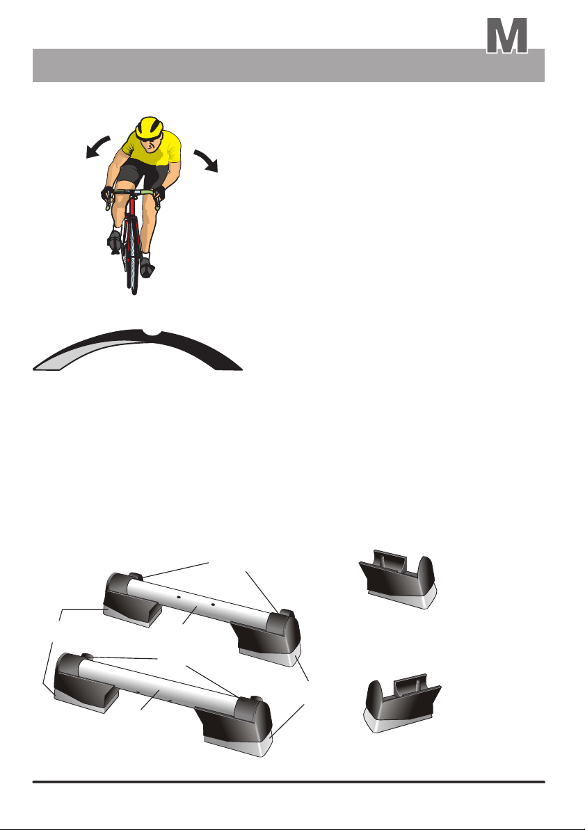
The oscillating movements occurring naturally with
real bikes cannot normally be reproduced when
training on an ergometer. These movements
include balancing movements or back and forth
oscillations. The rigid construction, and the fixed
feet used to support the device prevent any
dynamic movement.
Also, heavy training would eventually lead to
overloading the frame and mounting parts.
Squeaking noises are a typical consequence
of such overloads.
g
n
i
w
s
The swing feet technology was developed to address this shortcoming. This is done by
partially absorbing the dynamic load generated by the “biking” effort, and allowing the typical
“biker's oscillation”. Thus, the user experiences the natural biking swing with the
corresponding dynamic balance behaviour.
Moreover, noises and shocks are reduced, and frictional loadings to the floor are minimized.
e
f
f
e
c
t
Description
Fig. A: ergo_bike foot set with support feet (1),
standard feet (2 adjustable/front and 2a with caster/rear)
and installed “swing feet” (right SF/left SF).
A
right SF
1
2
1
2a
left SF
“swing feet”, left SF
Order No. M 80 90 510
“swing feet”, right SF
Order No. M 80 90 520
M4M4
Page 36
g
n
i
w
s
All ergo_bike ergometers come equipped with the new “swing feet” technology.
The device can also be used without the “swing effect”. For this you must remove
the installed “swing feet” (see the description on the back of this page).
“Swing effect” Benefits and features
Comfortable suspension
Prevention of muscular tension
Soft swing movements in all directions
Joints protection by the way of reduced pressure and
chocks on intervertebral discs, vertebral joints and on
the cartilages in the articulations of the feet and knee
e
f
f
e
c
t
Exceptionally silent operation
Optimal training, close to real biking conditions
A totally new training experience, and a decisive
step toward optimal training with minimal
overloading risk
Frame and drive parts protection
Minimizing the frictional load on
the ground (floor)
ergo_bike ergometers can be set to swing (oscillate) or to stand still, and they can
be easily moved on the integrated casters.
M5
Page 37
Assembly
“swing feet”
Operation and mounting of the “swing feet”
Lateral oscillations
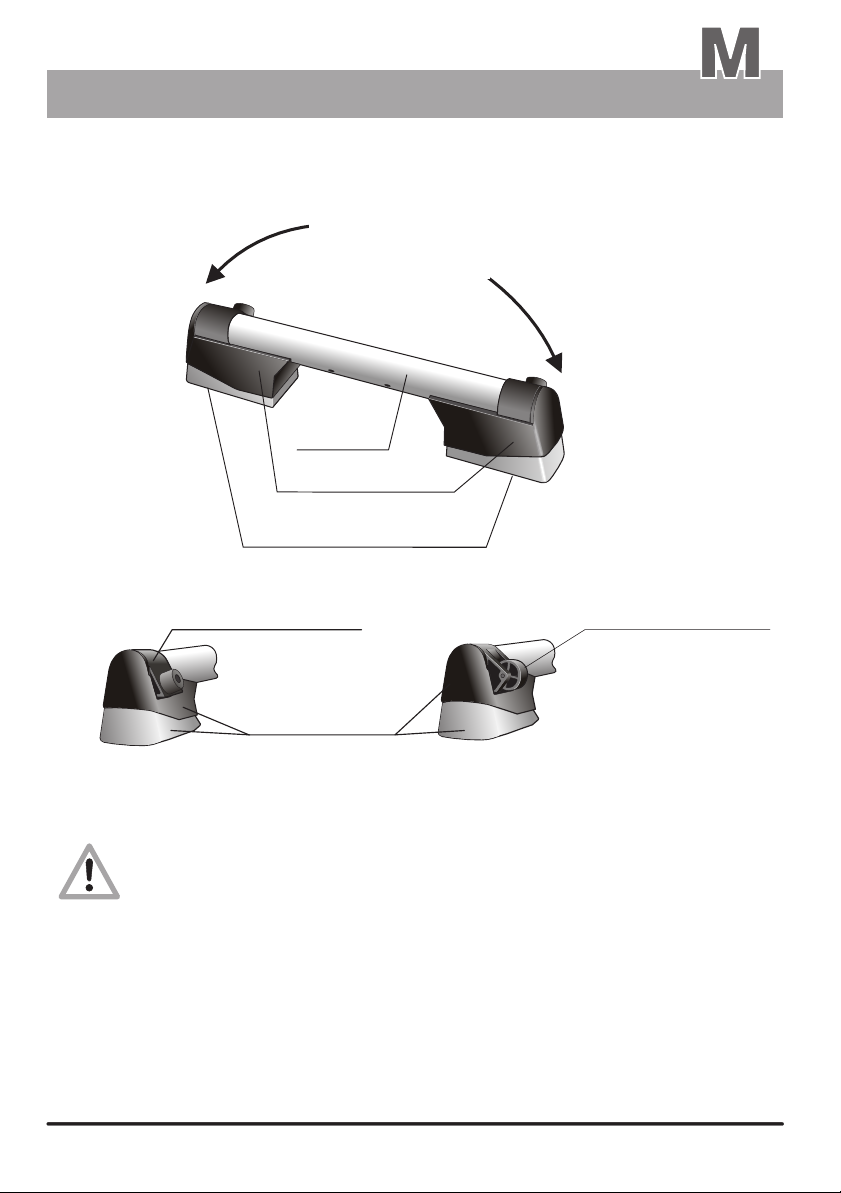
1
Foot support
B
3 / 3a
Plastic foot left / right
4
Elastic micro-cellular rubber pads
Standard foot / front
2
(with adjusting screw)
"swing feet"
"swing feet"
Standard foot / rear
2a
(with roller caster)
"swing feet"
Left SF
right SF
It is possible for the elasticity to drop or be insufficient if the swing feet (left SF/right SF)
are used for an extended period, or when an overweight person uses them.
If the user is overweight (more than 100 kg), then the bike should be used with the
standard feet (2/2a), i. e. without swing feet, or with the optional larger reinforced
swing feet.
Therefore we recommend doing an evaluation of the elasticity of the swing feet upon
reception and at regular intervals. The plastic feet (3/3a) must never touch the floor
while training. If this is not the case, then the micro-cellular rubber pads (4) are
worn out and the swing feet must be replaced. If the user is too overweight, then he/she
should exercise only with the standard feet (2/2a), i. e. without the swing feet.
The manufacturer is not liable for any damage done to the floor as a consequence
of installing the ergometer. The user must carefully choose the location for installing
the ergometer such that no damage is inflicted on the floor. If in doubt, we recommend
installing an appropriate base (underlay).
M6M6
Page 38
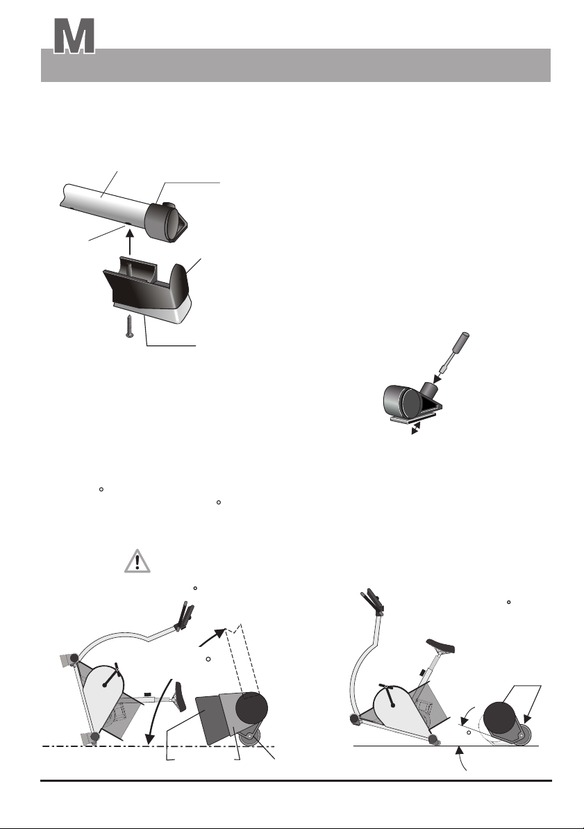
Assembly
ergo_bike swing effect feet / Assembly
The swing feet (right SF and left SF/Fig. C) are attached to
1
2 / 2a
the feet from underneath. The pins of the plastic feet (3/3a)
must engage in the corresponding holes (1a) of the support
feet (1) below the standard feet (2/2a). The adjusting pin of
the front standard feet should be completely screwed in.
Otherwise, the swing feet cannot snap into place.
Description
1a
C
Screw
When using the ergo_bike without the swing feet
on an uneven floor, use a screw driver to adjust
the pin of the front standard feet (see fig C.1) to
achieve an even stand.
The rear standard feet (2a) are equipped with roller casters to ease moving the ergometer. When the
swing feet are installed, (left SF/right SF) the device must be raised to a relatively steep angle
(approx. 75 /Fig. D) to bring the roller casters in contact with the floor. Without swing feet raising
the frame to an angle of approx. 15 (Fig. D.1) is enough.
D
Frame
(lifted to approx. 75 )
3 / 3a
left SF /
right SF
Moving position
(with "swing feet")
"swing feet"
It is possible to attache the swing feet with screws
(approx. 4.5x30mm) to improve the stability.
The swing feet can be removed by simply pulling them out
or by giving them a sharp rap, provided they are only
snapped in position.
C.1
front
foot
with floor
level adjustment
Moving position
(without "Swing feet")
Frame
(lifted to approx. 15 )
D.1
M7
approx. 75
"swing feet"
2a
15
2a
Page 39
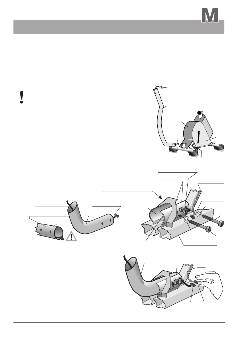
Assembly
Mounting the handle column
Description
2. Mounting instructions for the handle column
Required parts:
Required tools:
2.1
First the preassembled basic device should be put down in such a way as to leave enough room for you to
move around it, specially in front and on the left side.
2.2
The dashboard cable (3) is already installed in the handle
column (2) at the factory. In order to avoid wedging or
jamming the cable when mounting the column, the
connector at the lower end of the column should
protrude by only a small (short) length!
2.3
The holder (LSH) of the handle column (2) is located under
the tilted housing cover (18).
the handle column in the holder, it
in the proper orientation,
between the holder curved plates (LSH1 & 2) that are located
under the housing, until it stops. (See figures 1 and 2)
We recommend performing this operation with the help of a
second person. This second person can then insert the
recessed head screws (F) with their washers (G) through
the opening (on the left side) and screw them in the holder (LSH).
Do not yet tighten the two M10 fastening screws that are already
in the two curved plates LSH1 and LSH2 on the left and right sides
(FS1 on the left side and FS2 on the right side)! These screws
are installed loosely (not tight) at the factory and must not exert
any pressure on the column (2) during the mounting process!
through the opening in the housing (18)
3
Dashboard cable
lower end of the
handle column
2
Handle column with integrated dashboard cable
Allen wrench SW 8
3
In order to fit the lower end of
must be carefully inserted,
Fastening screw /
Handle column
supplementary fastening screw FS2
installed in the right side of
the holder LSH1 at the factory
CS connector /
dashboard cable 3
holder LSH
LSH2
2
CS
2
18
CS-1
Fig. 1
Left opening
(looking to
the front)
FS1
Device cable
GS
connector
1
3a
G
F
The connector (CS-1) of the dashboard cable
must not be pulled too much out of the column
tube. Otherwise, the cable (3) could get
jammed or damaged when inserting the
column in the frame holder (LSH)!
After the screws (F) have been screwed
2.4
in loosely, you can slightly draw the dashboard
cable and establish the connection (CS-1/GS).
(See fig. 3)
2.5
Lift the handle column (2) to its vertical position
before tightening the screws (F). If available,
use a water level to ensure a correct position
G
FS1
Frame bars
3a
CS-1
Connection
LSH1
3
Fig. 2
2
Fig. 3
F
GS
M 8
Page 40
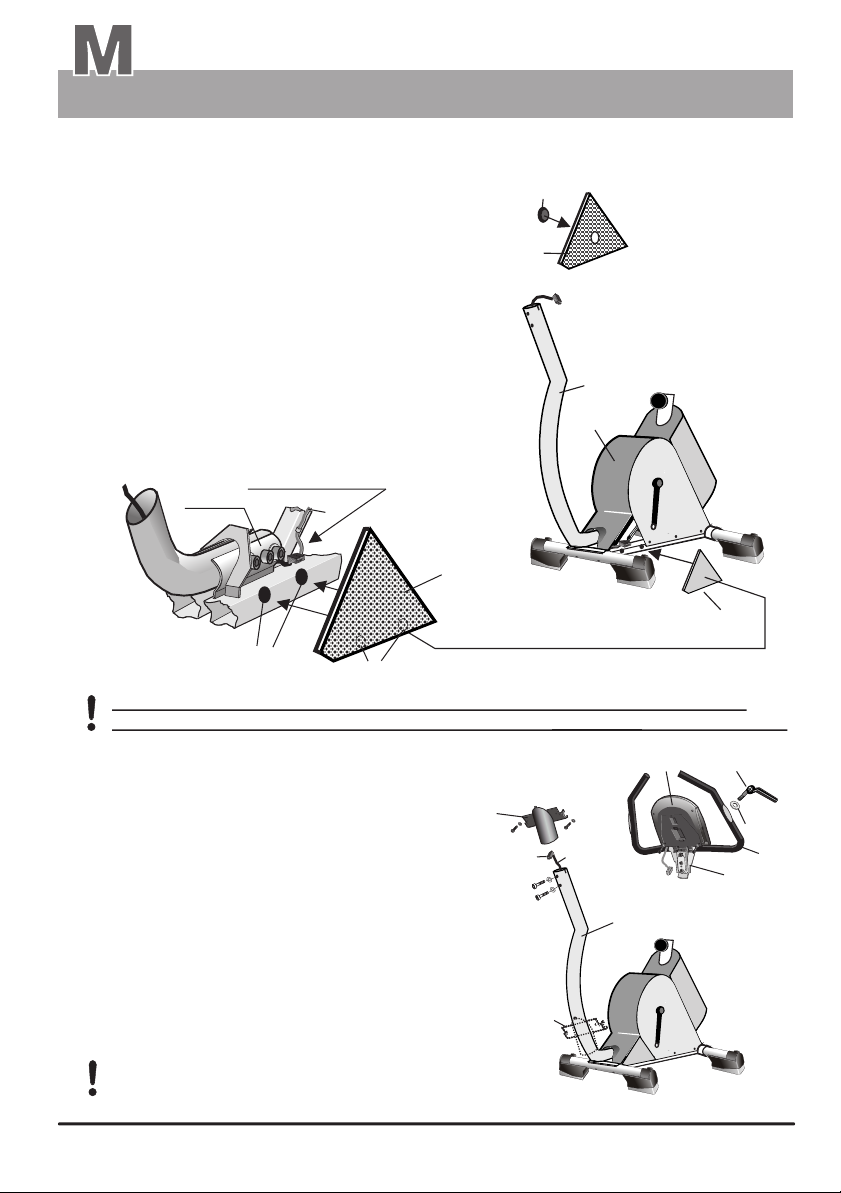
Assembly
Mounting the handle column and the dashboard
2.6
After the exact positioning of the column is achieved, the M10 screws (F) on the left of the column holder
(LSH1) must be firmly tightened with the supplied SW8 Allen wrench. Only then, you can tighten the fastening
screws (FS1 and FS2) to prevent bending the column.
The fastening screw (FS2) is located behind the perforated
plate (22) on the right side. Insert the SW8 Allen wrench
through the opening, covered with a cap (22a) to get to
the screw FS2.
Check the tightening of the holder screws (F) after you
tighten the screws (FS1 & FS2). If needed, you must
tighten them one more time!
2.7
The trapezoidal perforated plate (23) is attached to the
frame by mean of two pressure clips (23a). (See
illustrations four & 5) Its top side is inserted into the
housing cover (18) and the clips are pressed into position
on its bottom (23b). It is then easily removed, without
removing any part of the housing, to allow easy access
to the screws (F) to retighten them whenever needed.
The pressure clip should be kept
close to the frame
LSH
3a
23
22a
22
the perforated plate (22)
on the right side
(installed at the factory)
has an opening covered
with a cap (22a).
Lift the handle column (2)
to vertical position and
fasten it to the frame with
the 2 recessed head
screws (F)
2
18
Fig. 5
Fig. 4
23b
23a
You must check the tightening of the two holder screws (F) and of the fastening
screws (FS1 & 2) from time to time, and retighten them very firmly whenever needed.
3. Mounting instructions for the dashboard
Required parts:
Dashboard with the handle, protective plate
and clamp
Dashboard holder
Tensing lever with the appropriate washer (E)
2 Recessed head screws with washers ( C/D )
2 Fastening screws with washers ( H/J )
Attach the perforated plate cover to the
frame by mean of the pressure clips.
4.1
6
CS
3
H/J
Preassembled
dashboard unit
2
H/J
C/D
Required tools:
Allen wrench SW5
Phillips screwdriver (not included in the box)
Screwdriver (not included in the box)
3.1
The dashboard holder (6) must be fitted onto the
handle column (2) before it is possible to mount the
dashboard (4.1) on the handle column (2). It can simply
be left loose at the bottom of the column for the moment.
(See position A)
6
A
M 9
23
6a
E
7
8.1
Fig. 6
Page 41
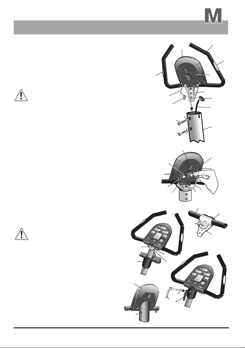
Assembly
Mounting the dashboard
The dashboard unit (4.1) is preassembled with the carrier plate (5),
3.2
the clamp (8.1) attached to that plate, and the handle (7) with
the integrated hand pulse sensors (7a) (including the connection
cable 7b). First insert the clamp (8.1) into the lateral slots at
the upper end of the column (2), without fastening, to position
the whole unit. You might need to exert some pressure to insert
the rear tongue (8a) of the clamp because of tolerances or
the paint layer thickness.
You must pay attention to avoid jamming the
cable (3) in the handle column (2)!
We recommend pulling the cable (3) to the left (when
looking at the rear side of the dashboard) and upward,
beside the spacer sleeve of the fastening screw (C) of
the rear tongue (8a) of the clamp. You may only release
the handle (7) after you have tightened both of the M8 recessed
head screws (C) with their washers (D) in order to secure
a stable stand on the column (2). Unscrew the front screw (8b)
attaching the complete dashboard unit (4.1) to the handle (7) until
the handle (7) starts moving freely and falls to its front stop
position due to its own weight.
Plug the black connector (CS) of the dashboard cable (3)
3.3
to the corresponding black socket (CS-2) on the circuit
board (within the lower opening in the housing and
the protective plate). Then p the white connector (HS)
of the hand pulse cable (7b), which is connected to the hand
pulse sensors (7a), to the corresponding white socket (HS-2)
within the same opening in the housing.
3.4
After plugging the cable connectors in the
rear side of the dashboard, raise the dashboard
holder (6) all the way up. Align carefully the
dashboard cables (3 & 7b) very closely to
the clamp (8a) in the area of the holder.
Please pay extra attention to avoid
jamming the cables in the narrow
passages within the dashboard holder
and between the carrier plate (5) and
the holder (6)!
The dashboard holder (6) is attached to
3.5
the dashboard housing (4.1) by pressing
the clip on the front. Additionally, you can
screw two small self-boring screws (H) with
washers (J) through the protective plate (5) into
the dashboard housing (4.1).
3.6
Finally, screw the tensing lever (6a) with
its washer (E) to fasten the handle (7).
Bring the handle (7) to the required position
within its adjusting range and then fasten it
using the tensing lever (6a).
Follow the same steps in reverse order
to disassemble the dashboard unit.
lug
7b
6
4.1
H/J
7a
7b
HS
C
C
CS-2
4.1
CS
Pull the
cable to the left
3
3
8
6a
H/J
Description
4.1
8.1
D
D
HS-2
7b
8.1
7
8b
E
7
7a
5
CS
3
2
HS
8
8a
M10
Page 42
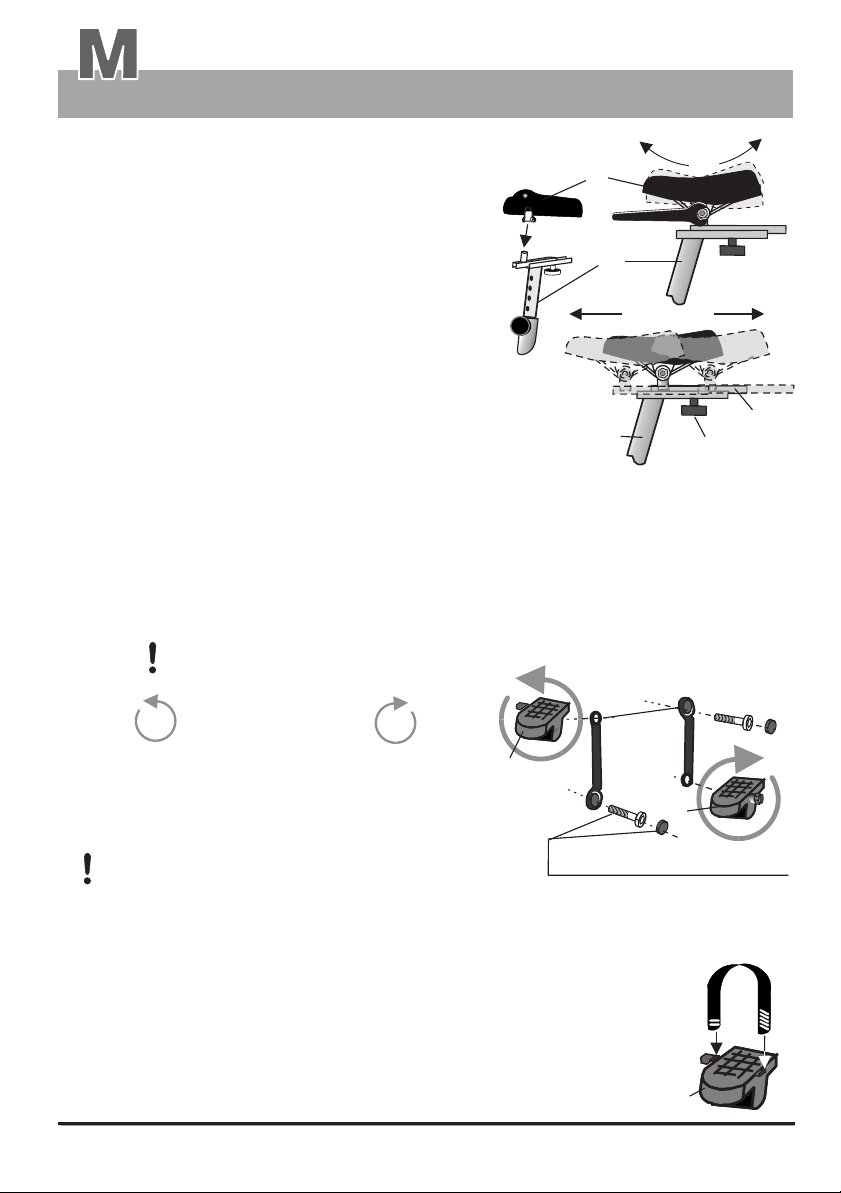
Assembly
Mounting The Saddle And Pedals
Description
4. Mounting Instructions / installing the Saddle
Required part:
Required tool:
Install the saddle holder (12) in the frame
4.1
and fasten it by mean of the toggle button (12a)
4.2
Install the saddle (13) on the dowel pin of
the saddle carriage on the saddle holder (12)
and set the saddle inclination by tilting it.
Tighten both of the nuts under the saddle.
4.3
Bring the saddle to the required horizontal position with
4.4
the sliding rail (12e) and fasten it with the button (12d).
1 x Saddle
1 x Wrench
( 14 mm )
12a
5. Pedals Mounting Instructions
Required parts:
Required tool:
Screw the pedal marked with an “L” to the pedal rod on the left side, and the one marked
5.1
with an “R” to the pedal rod on the ride side of the bike when facing forward.
Warning !!
counterclockwise
Die Pedale und die Pedalarm-Befestigungsschrauben ( unter der Pedalarm-Kunststoffkappe ) müssen
nach ca. 100 km Fahrstrecke, danach alle 500 km Fahrstrecke, unbedingt nachgezogen werden !
The threads of the pedal rods are compatible with those of standard bikes. Consequently, you can
install any pedal of the commercially available various pedal types as needed.
The left pedal (17) has a left-hand thread, and must therefore be screwed
in place by turning it counterclockwise.
The right pedal (16) has a right-hand thread and must therefore be screwed
in place by turning it clockwise.
17
To avoid damaging the thread, you should start
screwing the pedals in place by hand, and
then tighten them very firmly using the wrench (15 mm).
Warning! Damage to the thread of the pedal rods
is not covered by the warranty!
Turn pedal
2 x pedals
2 x pedal staps
wrench 15 mm
16
clockwise
L
17
13
4
1
12
12
12d
left
Pedal rods
16
Pedal rod attaching screw
and pedal rod plastic cap
12e
right
R
The pedal straps are marked above the oblique perforations:
5.2
With an for the left pedal, and with an for the right one.
Pull the strap onto the lugs at the left and right ends of the pedal.
Put the strap end with two holes to the pedal's side closest to the device.
Be careful to adjust the straps in such a way as to leave a sufficient loop to provide a
firm and comfortable foot support.
(16a/17a)
L (17a) R (16a)
M 11
17a
17
Page 43
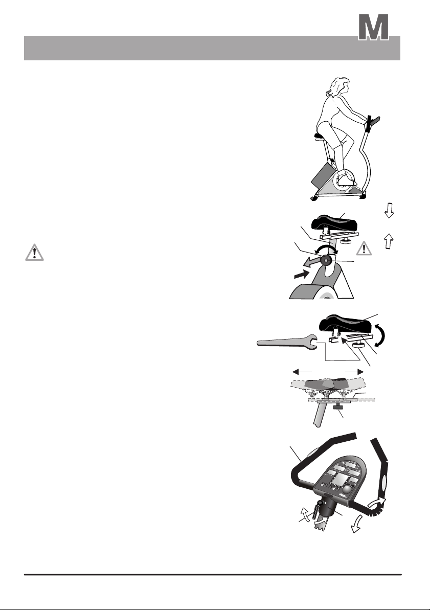
Assembly
Fine Tuning
Fine Tuning
A comfortable and relaxed sitting posture is crucial for ensuring that training with
the ergo_bike be effective and useful. Just like riding a bike, your back should
be straight and your legs should bend slightly at the knee when the pedals reach
their lowest point. This posture is illustrated in the drawing to the right.
The position of the handle, the height and inclination of the saddle and its position
must be adjusted to fit the user.
6. Adjusting Saddle Height
Loosen the tommy head (12a) on the saddle column (12) by one to two turns.
6.1
Hold the saddle (13) firmly and pull the spring loaded tommy head (12a) out.
6.2
Either pull the saddle holder (12) with the saddle (13) up or push
6.3
it down to bring it to the required position.
6.4
Release the tommy head button (12a) and pull or push the saddle
holder (12) carefully until the tommy head button (12a) engages,
with a click sound, in the corresponding hole of the saddle
column (12). This engagement is visibly indicated by the red
button (12b) plunging into the tommy head button (12)! The red
button (12b) must not be sticking out of the tommy head! If this
is the case, then it indicates that the safety lock of the tommy
head (12a) is not properly engaged in the corresponding hole
of the saddle column!
Turn the tommy head button (12a) and tighten it firmly after the red
6.5
button (12b) engages.
7. Adjusting Saddle Angle and Position
The saddle angle is adjusted to ensure a confortable seating.
7.1
The saddle angle should nevertheless help support a correct
body posture while training.
Loosen both the right and left nuts located under the
7.2
saddle (13) using the 14mm wrench, and bring the saddle
to the required angle by applying slight pressure.
7.3
Make a “sitting trial” very carefully, and if needed adjust the
saddle (13) again until it is in the adjusted as required. Then
tighten both of the right and left side nuts again.
7.4
The sitting position can be adjusted by mean of the sliding rail (12e)
of the saddle holder. This adjustment is to be carried out individually
through “sitting tests”. Loosen the tommy head (12b) underneath
the sliding rail and slide the saddle (13) to the required horizontal position.
After adjusting the saddle position retighten the tommy head (12b) firmly.
Description
12
12a
1.
2.
4.
14
7
13
5.
the red safety
button
must not
protrude
12b
3.
(12b)
13
12e
12b
12e
8. Adjusting the handle
The user should sit on the ergo_bike and loosen
8.1
the tensing lever (6a) on the dashboard column (6)
until it is possible to move the handle (7) by pushing
it lightly to another position.
Then adjust the handle (7) to the most comfortable
8.2
or preferred position that supports the body posture
described above.
Tighten the tensing lever (6a).
8.3
3.
6a
Festprogramme / pulsgesteuert
When riding the ergo_bike your back
should be straight, your arms slightly
stretched and your hands resting loosely
on the handles.
2.
6
1.
M 12
Page 44
Maintenance
Cleaning / Care
Cleaning outside surface
Wet a soft cloth with water and use it to clean the ergo_bike. A light soap solution may
also be used to wet the cloth.
Wipe the surface applying light pressure. While wiping the dashboard or the perforated
plate cover, be careful not to apply too much pressure to prevent water from entering the
dashboard or the device.
Do not use any strong or corrosive cleaning solution, or one containing
solvent, like, e.g., alcohol, stain remover, petrol, metal polish, etc.
We recommend using a commercial antistatic, either in liquid or spray form, to neutralize
the strong static charge generated while cleaning. Specially on the large plastic and transparent side panels of the high end ergo_bike models.
Sweat is an extremely aggressive fluid, which attacks paint as well as metal
and electronic parts. Therefore, care should be taken not to let sweat drop on
the device, or otherwise it should be carefully removed after training.
Damage caused by sweat is not covered by the warranty!
The ergo_bike is not completely sealed against sweat infiltrations.
Clean the sheath covering of the handle carefully with a mild soap solution.
Drive V belt
The ergo_bike is a belt driven ergometer. This means that the force applyied to the pedals is
transmitted by a V-belt to the drive unit. The advantage of this is that the ergo_bike runs very
quietly and smoothly.
V-belts eventually wear out and must be replaced when this is the case. If you feel a slip in the drive
while training, the reason could be a worn out V-belt.
Noises
The ergo_bike ergometers are equipped with quality ball bearings and silent belt drive.
Still, it is unavoidable that you hear a few remaining noises in the range of up to LpA 52 dB (decibel).
Squeaking and cracking noises are generally caused by the loosening of the screws attaching
the pedal rods (arms), the pedals, the feet or the dashboard support column.
W 1
Page 45
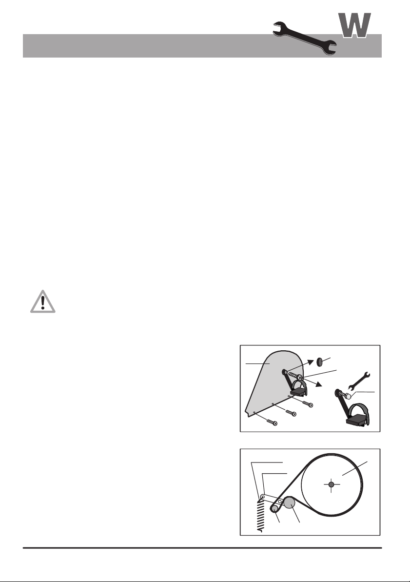
Maintenance
Simple Maintenance and Service Activities
About the V-belt
The driving surfaces of the drive and the V-belt pulley are covered with a rubber layer by
the manufacturer.
This favors the development of an optimal fitting of the V-belt into the grooves of the driving
pulley during the first 500 - 1000 kilometers.
During this fitting-in process, the belt will loose the excess rubber, which will be visible in the form of
black powder deposits. You can remove this deposit using a small brush or a vacuum cleaner
(particularly for the transparent ergo_bike models).
The V-belt is easily replaced. This maintenance operation can be performed by users with
manual skills.
If you have difficulties obtaining a replacement V-ribbed belt for your ergo_bike,
you can order one directly from the manufacturer: daum electronic GmbH.
Replacing the V-belt
Required tools:
M 12 hexadecimal head bolt or recessed head bolt (commercially available)
1
and an appropriate wrench or Allen wrench
Phillips screwdriver
1
6mm Allen wrench
1
Procedure for replacing the V-belt:
Unplug the power cable from the power socket before opening the device!
Take care not to damage the inner parts of your ergo_bike while you are working.
The manufacturer, daum electronic gmbh, will not be liable for any damages arising
as a result of negligence while changing the V-belt!
Remove the protective cap (1) of the axle center.
1.
2.
Loosen the screw attaching the pedal rod (2).
(6mm Allen wrench)
3.
Screw in an appropriate M 12 bolt, with a
hexadecimal or recessed head, into the
thread of the pedal axle until the pedal
comes off the axle shaft.
4.
Hold the pedal firmly and remove it.
Loosen the phillips head screws (3 - 5) on
5.
the bottom of the right side cover (RSC).
6.
Carefully remove the side cover.
7.
Press on the belt tensioning roller (31c) against
the spring tension to loosen the V-belt tension,
and then pull the belt from the pulley (25)
and drive shaft (28c).
Install the new V-ribbed belt by going through
the same steps described above in
the opposite sequence.
RSC
Tension spring
Tensing
lever
28c
right side
1
2
M 12
5
4
3
25
31c
W 2
Page 46
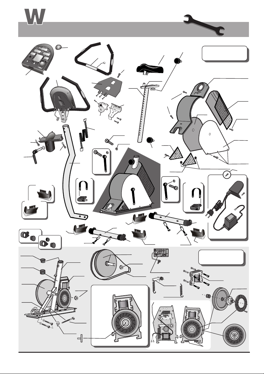
Spare Parts List
Maintenance
4
6
6b
6a
SF = swing feet
left
11a
right
11b
9a
12b
12c
25
3a
4.1
10a
6b
SF
1a
4a
2
Set
16 / 17
9c
27
25a
right
9b
12d
7
13
Device
6b
5
12
12e
18
21
8a
8
3
14a
14b
18a
22
19
21a
20
12a
21a
Set
16 / 17
left
17
attached by
pressure clips
24
10a
14
16
SF
1
23
15
10
20a
24a
9
9a
SF
9b
9c
SF
25
Drive
30
28a
27
25a
26
29
31
31a
33
27
W 3
W 3
3b
G
3b
F
28b
Back
Front
32
28
Page 47
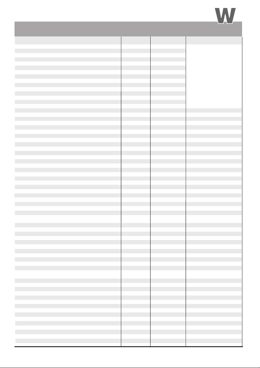
Spare Parts List
Ersatzteilliste
No. Spare part
ergo_bike Complete body
1
Handle column
2
Dashboard mounting screw (M10 / recessed head)
2a
Connection cable dashboard / body
3
Cable drive unit / dashboard
3a
Mounting base for locking band
3b
Locking band PLT 1,5 M
3c
Dashboard / complete top part with electronic circuits
4
Control button No. 6
4a
Dashboard upper part
4b
Dashboard bottom part
4c
Circuit board / dashboard electronics
4d
Protective plate
5
Screws for the dashboard housing
5a
Dashboard support
6
Tensing lever / handle positionning
6a
Screws for the support
6b
Handle
7
Handle clamp (top)
8
Handle clamp (bottom)
8a
Complete front foot
9
Foot set with adjustable height (front)
9a
Spacer sleeve for fastening the foot
9b
Screws for fastening the foot
9c
Complete rear foot
10
Foot set with caster (rear)
10a
SF = “swing feet” (basic assessory)
11
“swing feet” / left foot
11a
“swing feet” / right foot
11b
Saddle column with adjustable saddle holder
12
Tommy head for saddle column adjustment
12a
Saddle column guide 1 (top)
12b
Saddle column guide 2 (bottom)
12c
Locking screw button / saddle adjustment
12d
Saddle
13
Pedal rod right side
14
Screw for attaching the pedal rods
14a
Pedal rod screw cover
14b
Pedal rod left side
15
Pedals set with strap
16/17
(complete for right and left)
Upper body cover
18
Screws for fastening the upper body cover
18a
Side cover right side
19
Side cover left side
20
Screws for fastening the side side cover
20a
Perforated plate
21
Screws for fastening the perforated plate cover
21a
Perforated plate cover right side
22
Perforated plate cover left side
23
Cover with On/Off switch, power supply and cable
24
Screws for fastening the back cover
24a
Belt pulley with welded pedal shaft and
25
inserted roller bearing
Roller bearing for pedal
25a
Drive belt (V belt)
26
Complete drive unit
27
Complete flywheel
28
Flywheel flange with roller bearing
28a
Screw for flywheel
28b
Control board with light guard
29
Brake magnet
30
Complete belt tensioning device
31
Belt tensioning spring
31a
Rubber pad D 25 x 10
32
Rubber pad D 25 x 15
33
Pulse sensor (see page 11)
34
Relaxation sensor (see page 23)
35
Cardio Sensor Chest band (see pages 11 & T 1)
36
Maintenance
Order No.
00 18 208 A
00 21 914
12 10 802
12 10 801
03 00 035
07 50 090
00 17 423
00 17 405
00 17 404
13 00 582
M
00 17 136
00 03 120
00 17 403
00 17 316
00 21 913
00 17 379 A
00 17 233 A
00 17 232 A
00 17 418
00 09 535
00 21 850
00 17 419
00 17 630
80 90 510
M
M
80 90 520
00 17 199
19 00 238
00 17 185
00 17 186
00 17 194
00 17 432
00 17 510
00 30 570
00 17 560
00 17 520
00 17 530
00 17 337
00 23 411
00 26 413
00 21 510
50 00 100
00 24 411
00 09 316
00 31 070
60 90 000
M
80 90 052n
M
50 00 200n
00 17 286
80 90 025
E
18 20 000
00 37 313
00 09 232
00 07 320
00 07 325
00 17 900
80 90 080
E
90 91 015
cardio2002 pc
M60 90 607 A
M70 90 182
M80 90 197
M80 90 198
M00 18 371
M00 18 370
M80 90 231
M80 90 238
M80 90 236
M80 90 170
Listing
When ordering parts,
please include the device
serial number with the
part number.
You will find the device
serial number on
the specifications
plate located on
the rear plastic cover
close to
the ON/OFF switch
W 4
Page 48
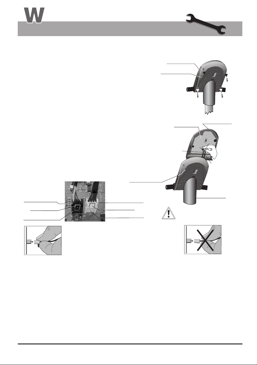
Maintenance
Exchanging the Dashboard / Replacing the Battery
It is possible to replace or disassemble the complete top part of the dashboard, for all models, in the case that
the display windows, the membrane switch, the control button, or the circuit board located underneath it malfunctions or simply
to replace the battery. The disassembly is a relatively easy operation and is done as described below.
Required tools:
Unplug the power cord!
1.
(For your personal safety and to protect the sensitive electronic parts inside
the dashboard)
2.
The top part of the dashboard is secured to the bottom part by mean of 4 Phillips
screws (A, B, C, D). Use an appropriate screwdriver to unscrew these screws from
underneath the dashboard. (See the figure to the right) Please note that the
screws C & D are located toward the outward border and are deeply recessed in
the dashboard bottom part. Do not unscrew the nearby located screws (X)!
Then you can remove the top part of the dashboard very carefully. First open
3.
the dashboard housing by raising it from the higher side slightly and grasp (hold)
with both hands underneath the top shell of the dashboard. Raise the higher part
of the dashboard top shell fruther until the lower side separates from the dashboard
support. Be careful to raise the top shell of the dashboard housing only until you feel
a slight resistance from the cables (K1 and K2) that are connected from underneath,
and until you can reach the connectors (CS black & HS white) on the circuit board with
your thumb and index finger.
You must unplug both connectors (CS and HS ). Never pull on the cables
4.
to unplug them!! This would tear them off! Unlock the connector by
pressing on the lock clip and pull it gently from the receptacle. (See figure 4).
Sometimes the lock clip will be removed from the connector at the factory.
Hand pulse sensors and
dashboard connectors
(location on the circuit board)
Dashboard
connector / CS
Lock clip
(with locking tip)
Female connector / CS-2
(attached to the circuit board)
4.
Phillips screwdriver / Blade 1 x 70 mm
(black)
Be carefull when pulling the connector in order
to avoid damaging the circuit board and the
electronic parts!
The connection is be unlocked by pressing the
elastic connector clip.
Dashboard
bottom part
Hand pulse sensors
connector / HS
Female connector / HS-2
(attached to the circuit board)
Lock clip
(with locking tip)
(white)
ergo_bike
Dashboard top part
Dashboard bottom
part
C
Circuit board
K1
Do not pull the cable under any
circumstances! They would
tear off!
CS
A
X
B
X
D
Dashboard top part
HS
3.
K2
Dashboard
support column
2.
Follow the same steps in reverse sequence to reassemble the dashboard top part
5.
Plug the dashboard connector / CS (black) and the hand pulse connector / HS (white) to the female connector of the
corresponding color until they lock in position. Then pull carefully the two cables (K1 and K2) through the opening of the
bottom part of the dashboard and the dashboard support and take care not to jam the cables when you reinstall the top part
of the dashboard on the bottom part.
6.
When reinstalling the top part of the dashboard top shell, first lock the lower end with the dashboard support and then lower
it onto the dashboard bottom part.
7.
Screw the removed housing screws (A, B, C, D) from underneath the dashboard and tighten them.
8.
You can know plug the power cord, turn on the ergometer and test its operation.
Battery replacement (button cell)
The button cell battery is located on the underside of the circuit board of the dashboard, at the lower end to the right (close to
the printed circuits). Replace this battery when you notice a loss of time and date on the system clock. Therefore you must
disassemble the dashboard top part as described above at steps 1 to 3, separate it from the bottom part of the dashboard, and
reassemble them in reverse sequence.
W 5
Page 49
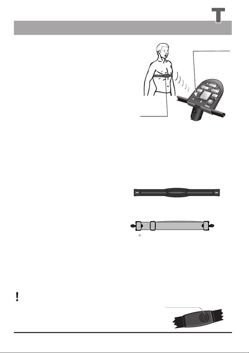
Technical Information
Special Accessories
Special Accessory
The Cardio sensor chest band measures your
pulse rate directly above the heart and transmits
the data directly to the integrated wireless cardio pulse
receiver. The location of the
chest band and transmitter directly above the heart
enables very accurate pulse rate measurement.
The data is wirelessly transmitted to the computer
of the ergo_bike.
Pulse rate measurement using the Cardio Sensor
chest band is particularly useful when exact values
are required. This can be the case if your physician
needs the data of your training sessions with the ergometer in the context of a treatment.
All ergo_bike ergometers are equipped with a built-in Cardio pulse rate receiver, not visible from the outside.
This allows receiving of the pulse rate transmitted by any standard chest band, of the coded and non coded type.
You only need a cardio sensor chest band to achieve wireless heart pulse rate measurement.
Cardio Sensor chest band
integrated
Cardio pulse
rate receiver
Cardio
Sensor
chest band
(with transmitter)
What is in the box of a Cardio Sensor chest band
1 Skin-friendly Cardio Sensor chest band with integrated pulse sensor and transmitter
1 Adjustable elastic band to attach it to your chest
The chest band is available from daum electronic gmbh;Order no. 90 91 015.
Putting on and using the Cardio Sensor chest band
1.
Remove your upper body clothing or pull your shirt up
to uncover the area of the heart. Your skin should be
slightly moist, but not wet. If your skin is too wet, dry it
with a towel, if it is too dry, moisten the inside (contact
surface) of the chest band slightly.
2. The sensor chest band with the transmitter in
the middle has surface recesses at both ends.
The elastic band is fitted with round locking
toggles at both ends. Insert one of the toggles
through one of the square holes in the sensor band. Turn the toggle 90 and press it firmly into the recess.
Wireless Cardio Sensor Chest Band
Order no. 90 91 015
3.
Hold the Cardio sensor chest band over your chest.
Pull the elastic band around your back and fasten the other toggle into the opening on the other side of the sensor band.
4.
There is a buckle on the elastic band, enabling you to adjust it. To obtain a comfortable fit, hold the buckle firmly and pull out
5.
a section of the band.
Adjust the pulse sensor band so that the thicker part of the band, which contains the sensor and transmitter, lies on the chest
6.
directly above your heart.
Warning: using two chest bands simultaneously in the same room, either of the coded or non-coded type,
to achieve wireless heart rate measurement can lead to the display of a wrong pulse rate on the dashboard
of the ergo_bike.
The button type battery should be replaced when you note a loss of battery power.
Simply remove the battery cover using a coin and replace the battery with an
equivalent new one.
Battery housing
T 1T 1
Page 50
Technical Information
Specifications
Specifications
Braking system:
Festprogramme / pulsgesteuert
Load range:
Speed range:
Load precision:
Loading levels:
Drive:
Flywheel:
Programming system:
Bio Feedback Function:
Fitness level:
Computer-controlled, full electronic eddy current brake
operating in the speed ranges shown in the diagram
on page 9.
25 to 400 Watt
0 to 199 RPM
Classe A DIN EN 957-1/5
In 5-Watt increments, manually adjustable
Single-stage, maintenance-free steel-ribbed belt drive in a
spring supported drive unit.
Machined
Single button programming
Bio feedback based on the ,
measurement via finger electrodes, approx. 100 KOhm
to 3 MOhm, self calibrating, display on LCD Panel in
255 levels and audible time controlled relaxing melody.
Six age-related fitness levels grading, displayed on
LCD panel and through 6 commendation melodies.
electrical resistance of the skin
Saddle height
adjustment:
Handle setting:
Displays:
Pulse measurement:
Limit values setting:
Alarm signals:
Weight:
Dimensions:
Power supply:
Safety standards:
Safety class:
T 2
fast setting in 21 levels for body sizes of 120 to 190 cm
approx. 320
5 liquid crystal panels for pulse, distance, speed, average
speed, load in Watt, kJoule burned, pedal speed (RPM)
and training time.
On the ear, measuring range 50 to 199 pulses/min.,
using the Cardio sensor chest band (optional accessory),
or over the pulse sensors
Pulse, distance, training time, kJoule, and maximum
load in watt.
Acoustic and optical
about 40 kg
W / H / L 55 cm x 123 cm x 85 cm
220 V or 230 V alternating current, 50 Hz, 50 VA
GS, CE
2
continuously
telemetric
integrated in the handle)
Page 51
Technical Information
Safety Requirements
Conformity
To The Technical Plant And Equipment Act
hereby declares that this product complies with the following provisions
regarding electromagnetic compatibility and electrical safety:
89 / 336 / EWG of May 3, 1989 including subsequent changes (Recommendation
92 / 31 / EWG of April 28, 1992 and recommendation 93 /68 / EWG of July 22, 1993)
73 / 23 / EWG of February 19, 1973 including subsequent changes (Recommendation
93 / 68 / EWG of August 30, 1993 )
EN 55081-1 ( EMC, Generic Emission Standard; Part 1: Residential
commercial and light industry )
Technical safety recommendation:
Compare the supply voltage on the nameplate on the housing with your local supply voltage
prior to plugging the power cord to the power supply. Contact you dealer If the values are
not the same.
The device is completely disconnected from the power supply by pulling out the power cord,
therefore it should always be plugged into an easily accessible socket.
LGA
LandesgewerbeanstaltBayern
N ü r n b e r g
Area of application:
The device is suitable for therapeutic utilization at home
(complies with Class A DIN EN 957-1/5 ).
It does not meet the requirements of medical diagnostic applications (clinical use).
The maximum allowed load capacity is 120 kg !
T 3
Page 52
Index
A - K
A
Accessory / swing-feet, M4-M7
Aching muscles, G1
Festprogramme / pulsgesteuert
Aerobic pulse zone, 6
Aerobic zone, 7
Age, 14
Age entry, 16
Alarm values, 14, 15, 16, 17
Application areas, 18, T3
Assembling hardware, M 2
Assembling sequence, M 1 - M12
Assembly, M 1 - M12
Average speed, 22
Average values, 22
Average symbol, 22
B
Battery replacement, W5
Biofeedback, 23, T 2, G 1
Body posture, 18, M12
C
Calorie, G 1
Cardio Program / C 26, 27
Cardio Sensor Chest band, 11, T 1
CE symbol, T 3
Changing Values, 14 - 17
Chest band, 11, T 1
Children, 19
Clamp, M9
Cleaning / Care, W 1
Clock time, 8
Connecting, 11, 12
Connection cable, M8/10, W3-W5
Connector / PC interface, 4, 12
Connector / Pulse sensor, FP, 4
Connector / Relaxation sensor, FP, 4, 23
Connector, M8, M10, W 5
Conformity, T 3
Contents of the box, M 2
Control button, 3
D
Dashboard, FP, 3-6, 8-13, M 9-M10, W5, T1
Dashboard cable, M8-M10, W3-W5
Dashboard replacement, W 5
Dat key, FP, 4
(A) DIN EN 957-1/5, 1, 19, T2, T3
Display, 4, 5, 6, 8, 9, 10
Distance entry, 16, 17
Drive, W1
E
Ear clip, 11
Eddy current brake, G 1
Endurance training, 18, 20
Ergometer, 1
ergo_win 2002, 12
F
Fine tuning, M12
Fitness grading, 21
Fitness evaluation, 21
Fixed programs, overview, 24
Feet mounting, M 3
G
Guest, 5, 14
GS symbol, T 7
H
Hand pulse sensor, 11
Handle column, M1/2, M8-M9, M12, W4/5
Handle setting, M12
Heart and blood circulation training, 6, 7
Heart rate controlled, 6,11, 14, 15,
I
Illnesses, 19
Individual program / P, 28, 29, 30
Installation conditions, 19, M 1
Internet, 12
J
Joule (kJoule), G 1
K
Kilometer counter, 10
kJoule, 3, 8, 14, 16, 17, 20, 22, G1
kJoule burned, 8, 14, 22
km/h, 9
km total, 9
1
S 1
Page 53
Index
2
L
Lactic acid, G 1
Lateral connector, 11, 23
LED, G1
Limit arrow, 8, 9, 10
Limitations, 16, 19, 20, B
M
Manual setting, 13
Melody, 6, 8,10, 21, 23
Multi Media / PC Interface, 12
N
Notes about safety, 2, 19, 20, M1, W1, W2
Notes about utilisation, 1, T2
Note, 21
P
Packaging, M2, B
PC connector, 4, 12
Pedal, identification, M11
Pedal, mounting, M11
Pedal speed, 9
Performance diagrams, 32-37, 39
Performance test / WHO Standard, 20
Personal alarm values, 14 - 17
Physiology, G 1
Power in Watt, 3, 6, 7, 9, 13, 20, 22, T2, G1
Power supply, 2, M 1, T 2
Protection class, T 2
Protection symbol, T2
Pulley, W2 - W3
Pulse sensor operation, 11
Pulse sensor, 11, T 1
Pulse status, 6
Pulse rate, 6, 7,11,13,14, 15, 17
Pulse rate controlled, 6, 14, 15
R
Recalling last training values, 22
Relax, 10
Relax key, FP, 4
Relaxation sensor, 4, 23
Relaxing, 23
Reset key, FP, 4
RESET recessed key, FP, 4, G3
RPM dependant, 9
RPM, 9, 13
S
Saddle, M1/2, M11/12
Saddle height, M12
Saddle holder, adjusting, M11/12
Saddle tilt, M12
Safety notes, 19
Selection arrow, 8, 9, 10
Self test, 2, G 1
Single button programming, 3
Sitting position, 18, M12
Sleep mode / SLP, 2,
Software, 12
Spare parts list W3, W4
Special accessory, T1
Stand by, 2
Stepping resistance drops, 6, 7
Swing-feet / swing effect M4-M7
T
Target pulse rate, 7
Technical data, T 2
Technical safety notes, 19, M 1
Time setting, 8, 10
Time entry, 16, 17
Tools, M 2
Total kilometers, 9
Training, 18 - 23
Training conditions, 18, 19
Training example, 20
Training load, 6, 7, 13, 20
Training preparations, 14 - 17
Training time, 16, 20
Training time entry, 16
Turning off, 2
Turning on, 2
U
User, 5
User identification number, 5, 14
User identification number, 5, 14
Users / km total, 9
Users / personal values, 14, 15, 16
V
V-Belt replacement, W 2
V-Belt, W 1, W 2
Verifying Values, 17
W
Watt, 10, G 1
Watt load drops, 6
WHO, 20, G 1
L - Z
S 2
Page 54
Glossary
Aching muscles
Painful phenomenon of the muscles tissues, occurring when the aerobic zone is exceeded leading to an
overproduction of lactic acid. In order to avoid it, the ergo_bike compares measured data, input parameters
and statistical values and displays the resulting aerobic zone status.
Aerobic zone
The training phase during which the load on the muscles is enough to keep them supplied with oxygen,
but not enough to cause an overproduction of lactic acid (aching muscles). Aerobics also makes use of
the aerobic zone.
Bio-Feedback
Acoustic and/or optical feedback on the metabolism and condition of the body.
Calorie (abbrev.: cal)
Energy measurement unit. Officially obsolete, but still in common use. It refers to thermal energy in
particular. The conversion factor to the unit in use today (J): 1 cal = 4.1868 J, or the other way
around 1 J = 0.2388 cal
Eddy current brake
Uses the fact that electric currents induced in a conductor by a fluctuating magnetic field produce joule-type
energy which can be used for an electronically controlled brake.
Energy balance
The balance between energy intake and energy usage. There can only be a balance if intake
and output are the same. For example, in Germany every person consumes on average 400 - 500 Kcal
more than he or she can use.
Joule (abbrev.: J ) 1 KJoule = 1000 Joules
Energy measurement unit, named after the british physicist James Prescott Joule. (see calorie)
Lactic acid (aching muscles)
LED
Light Emitting Diode: when current is passed through a LED it emits light, either visible or invisible.
It is used for indicator lamps or remote controls.
RPM
Physiology
Revolutions per Minute.
The science of life processes
1
Self test
When switched on, the ergo_bike computer checks the electronic circuits it uses to make sure
every thing functions properly.
Watt (abbrev.: W)
WHO World Health Organization
Unit of measure of the work done per unit time:
1 W = 1 J / s = 1 Nm / s = 1 VA
G 1
Page 55
General Recommendations
What to do, if ...?
In the case of a failure ................... what to do if...?
All ergo_bike ergometers undergo a detailed test before they are shipped.
Should you, in spite of this, face a functional failure, the following recommendations should tell you what to do.
General procedure to identify the cause of a failure
The ergo_bike ergometers consist essentially of two functional units
- the dashboard and the drive unit.
The drive unit is located inside the device, behind the saddle column. It contains the power supply, the
eddy current brake and the related electronic circuits.
The dashboard contains the electronic circuits used for system control, display and data processing.
The dashboard and the drive unit communicate via a cable, which is routed through the handle support column, and
is equipped with connectors at the dashboard, at the drive unit and in the handle column.
Should the assembled ergo_bike fail to function, the defect would generally be found either on the dashboard,
the drive unit or the cable connecting them.
The most frequent cause of complaint turns out to be jamming the connecting cable during the assembly process of
the ergo_bike, or not properly plugging the cable connector.
In the event of a failure, check carefully first if
The cable connector found on the lower end of the handle support column is properly connected, and that
the cable was not jammed or cut when the handle support column was mounted on the frame. To do this you need
to disassemble the handle support column.
The cable was not jammed or cut while mounting the handle on the support column, or if
the cable connector to the circuit board inside the dashboard is loose.
To do this you need to disassemble the dashboard.
Fastening screws
All the fastening screws must be tightened from time to time. We recommend tightening them at least after the first
50 km and then once every 500 km.
Contacting your dealer or the service department of the ergo_lyps
If the cause of the failure could not be identified, you should contact your dealer
or our repair hotline (telephone number 0190 / 770 383 - a fee of 1.48 Euro per min. applies).
We need the following information:
1. The device number (this number is on the silver label on the lower part of the frame).
2. The dashboard version number (switch the device on and press the red reset key once, then immediately press
the control button. The number is displayed in display window 2 while the control button is pressed).
3. The proof of purchase and the device reference sheet.
4. ergo_bike ergometers have a built-in failure diagnostic system, which signals device functionality using a red
and a yellow LED. These LEDs are located under the rounded perforated plate cover, in the upper part (to
the right side looking in the front direction). You can them from outside (through the grid). With the device
switched on, the yellow LED should blink when pedalling slowly, and blink faster when pedalling fast.
With the device switched on, the red LED should light with high intensity when pedalling
against a low load, and decrease in intensity as the load increases.
Please inform us of the status of these LEDs for all complaints concerning “the device is
not braking” or “the device is not braking properly.” This enables us to draw relatively concrete
conclusions about the cause of the failure.
If you wish to obtain more information on your device, please visit our service and repair hints web site on Internet
at www.daum-electronic.de. By entering the password “ergo-service” you gain access to an area reserved
to ergo_bike owners where you will find additional detailed service hints. You can also call our service and repair
hotline (telephone number 0190 / 770 383 - a fee of 1.48 Euro per min. applies).
G 2
Page 56
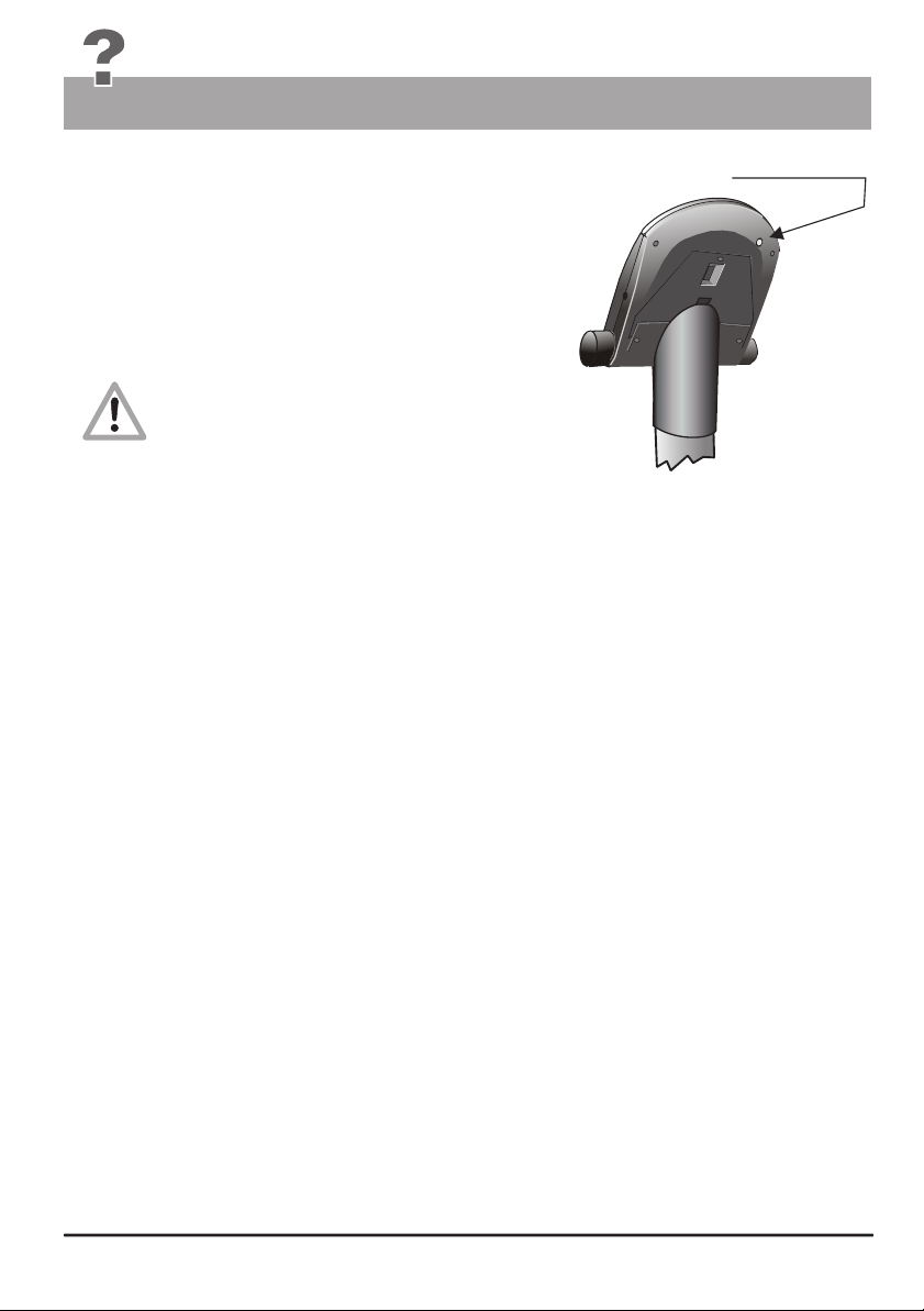
General Recommendations
What to do, if ...?
Software Failure / Loss of Dashboard Control
All computer controlled appliances have one undesirable
characteristic in common that is that the normal software
operation can sometime fail for generally unknown reasons.
This situation is generally described by the expression
“the system has frozen”. Should the dashboard operation
fail and cannot be restored by mean of normal keys functions,
then the solution would be to press the recessed
RESET key (No. 18) underneath the dashboard with
a pointed tool (e.g. a pencil or ball pen).
Please note that all the personal data,
and all training data and results will
be definitively lost when you press
the RESET key!!
Noises
ergo_bike ergometers are equipped with quality ball bearings and a silent belt drive. However, it cannot
be avoided that remaining noises be heard, which are in the range of LpA 52 dB (decibel).
The squeaking noises generally originate from:
- Loosening of the screws used to fasten the pedal rods
- The pedals
- The screws fastening the feet or handle column.
These screws must be tightened every 500 km!!
Notes about the pulse alarm
If you enter the age of the user under “Age”, and a pulse limit value that should not be exceeded under
“pulse higher limit” in the “Data entry and alarm levels set up”mode (see pages 14 to 17), then
the alarm will always sound whenever
- the aerobic zone corresponding to the age of the user is exceeded
(see page 7)
and
- the value entered under “pulse higher limit” is reachd (see pages 14 to 17)
If you want the alarm to sound only when the pulse limit value entered
under “pulse higher limit” is reached, you should enter zero as the user age under “Age”!!
.
RESET key
recessed
Drive / Braking unit (eddy current brake)
If a major failure is detected on the drive unit, it is possible to replace the complete unit. The braking unit,
which consists of the flywheel, a transformer, a belt tensioning device and the mounting plate, is mounted
with only three screws.
You can order an exchange unit from daum electronic GmbH. The defective unit can then be relatively
easily replaced with the new one, without requiring any adjustment, by your dealer or a bike mechanic.
The flywheel of the ergo_bike is equipped with two journal bearings. These bearings continue to run
for a little while after you stop pedalling. Feeling a light drag on the pedals is then normal. The journal
bearings should be lubricated with Klüberplex BEM 34-132 grease every about 3000km (if the drag on
the pedals increases and becomes uncomfortable), depending on the load.
G 3
Page 57
Warranty conditions
Warranty conditions
Please consult your dealer/retailer in the case of a failure or trouble. The manufacturer daum
electronic GmbH provides the warranty to your retailer according to the following conditions:
We guarantee that our products are free of manufacturing and/or material defects.
1.
We will correct any problem pertaining to the above categories, with the exclusion of customer claims not
2.
related to those categories through upgrading services provided by us. We reserve the right, upon
returning of the product in question, to exchange it with another product of the same type and value or,
at our own discretion, to take it back against repayment of the amount paid by the customer (deducting
overhead costs).
3.
Our warranty covers a period of two years for parts and labor in the case of private utilization of the
product, and a period of three months, for parts and labor, in the case of commercial utilization of the
product, in both cases starting on the manufacturing date.
We will fulfill this warranty service provided the customer will pay all freight and transport costs,
including those for spare parts, and the cost of any packaging material we should possibly need to use.
Returned devices will only be accepted if in the original packaging.
(see illustration on page M2)
Advance replacement of parts under warranty will be invoiced and delivered against payment (COD).
The amount paid will be immediately refunded upon reception of the returned old part by us.
4.
All other warranty claims, specially claims for the compensation of direct or indirect damages, or damage to
a third party, or damages to other objects, as well as of damages due to failure, and of labour costs, are
expressly excluded to the extend authorized by law. Should the repair fail within a reasonable delay,
the customer has the right to demand a price reduction or the cancellation (modification) of the contract
at his discretion.
5.
We decline any responsibility for any wear occurring through normal utilization. The warranty will be
considered null and void if our instructions for mounting and utilizing the device are not respected, or if
the chemical products we recommend and deliver are not used, or if any modification was made to
the device without our prior approval.
6. It is the customer's responsibility to check each one of our deliveries immediately upon reception. Any
complaints about missing or defective parts must each be immediately transmitted in writing.
7.
We do not guarantee that the delivered product will be suitable for the usage intended by our customer.
Extended agreements need to be expressly confirmed in writing.
8.
Any technical advice provided by us is formulated according to the best of our knowledge and in good faith,
based on our own experience and testing. We do not assume any responsibility for this service,
unless serious negligence can be proven on our part.
If you wish to obtain more information on your device, you can visit our service and repair hints web site
on Internet at (www.daum-electronic.de). By entering the password “ergo-service” you will get access
to an area reserved to ergo_bike owners, where you will find additional detailed service hints.
You can also call us on our repair hotline (telephone number 0190 / 770 383 - a fee of 1.48 Euro
per min. applies).
daum electronic gmbh, D-90768 Fürth
B
Page 58

ergo bike
cardio2002 pc
Order Nr. 90 90 182
daum electronic gmbh
Flugplatzstr. 100
D - 90768 Fürth
(Hotline - a fee of 1.48 Euro per min. is charged)
Tel. ++49 / (0) 190 / 770 383
Fax. ++49 / (0) 911 / 75 37 14
www.daum-electronic.de
daum electronic;
Copying or using the contents
of this manual, as a whole or
in parts, is not authorized without
the written permission of daum
electronic GmbH.
Index-03-0
 Loading...