

Page 1

L-Band IF Application Guide
DATUM
SYSTEMS
PSM-4900L L-Band IF Satellite Modem
Application Guide
1.0 Introduction
The purpose of this document is to provide a quick start application guide to users already
familiar with Datum Systems M5 series of satellite modems, and as an aid to setting up an LBand IF based small station.
The PSM-4900L modem brings all the advantages of Datum System’s direct modulation and
demodulation design, superior performance and high digital integration for low cost assembly to
the VSAT station. Because this new modem costs little more than a standard 70 MHz IF modem
and significantly reduces the complexity and cost of the up and down conversion equipment, it
promises to provide a new high in performance per dollar. Two expensive parts of the converter
equipment have however been transferred to the modem – that is the high stability reference
oscillator and the ODU power supply.
A significant aspect of small station design using an L-Band interface modem is that all of the
complexity and “smarts” are contained within the modem itself. The Block UpConverter or “BUC”
and the Low Noise Block DownConverter or “LNB” now each contain a single fixed local
oscillator, not required to tune for operation over the entire satellite band covering all
transponders. The PSM-4900L tunes over an extended range of 950 to 1750 MHz (transmit) or
950 to 1900 MHz (receive) in 1 Hz increments allowing it to access 800 MHz of Transmit RF
spectrum and 950 MHz of Receive RF spectrum without any converter settings.
Aside from the many advantages, using L-Band as an inter-facility link frequency results in the
need to carefully consider the components, frequencies and construction techniques used to
insure proper operation. Part of the purpose of this addendum is to spell out those areas where
special care must be used to achieve a reliable station operation.
For the purposes of the remainder of this document the names, acronyms and meanings used
which may be new for this type modem are:
• “Modem” - Refers to the PSM-4900L modem capable of both transmit and receive
operation.
• “IF”. The modems Intermediate Frequency used to connect to the Up and
DownConversion equipment.
• “BUC” – Block Up Converter, Often with an integrated power amplifier for installation
directly to the feed at the antenna.
• “LNB” – Low Noise Block Down Converter. Includes a low noise RF front end and single
down conversion stage to L-Band frequencies. In a VSAT, especially at low data rates,
this is a significantly better device than the typical free running LNB used for video
broadcast reception. A “data grade” LNB must have very low phase noise and a phase
locked LO for proper performance.
• “Bias T Mux”. This is a device that multiplexes power, IF signals and often a reference
frequency onto a single cable going up to the BUC or LNB.
• “Terrestrial” side. The Line or data side of the modem.
• “VSAT” – Vary Small Aperture Station, referring to a station with a small antenna,
typically 1 to 4.5 meters in diameter.
• “LO” – Local Oscillator frequency used for up or down conversion of RF frequenies.
Page L-Band - 1
Page 2

L-Band IF Application Guide
2.0 Differences Between 70 MHz and L-Band Modems
Since the PSM-4900L modem is closely based on the design of the PSM-4900 70 MHz modem
the vast majority of the operation of these modems is identical. We briefly list the differences
between these modems here and further amplify operating differences in the following sections.
• The IF Frequency range is changed to 950 to 1750 MHz Transmit, and 950 to 1900
Receive. A BUC and LNB LO frequency may be input, allow setting transmit and receive
RF frequencies directly.
• Transmit power levels are wide range to cover long transmit IFLink cables.
• Receive Input Level AGC range is greatly expanded covering demodulator input levels of
–20 dBm to –102 dBm, dependant on data rate.
• New and Modified Commands available, specifically related to the care and feeding of
the BUC and LNB.
2.1 IF Frequency Range
Typical 70 MHz modems are designed to operate over a 36 (or 40) MHz range representing the
bandwidth of a single transponder on a C-Band (6 GHz uplink/4 GHz downlink) satellite. This
results in the classic 70 MHz IF range of 52 to 88 MHz.
Since it is expected that no tuning is available in the BUC or LNB, then an L-Band modem must
tune over at least the 500 MHz of a typical satellite’s full transponder range. For C-Band this
would be the RF ranges of 5.925 to 6.425 GHz transmit and 3.7 to 4.2 GHz receive. Translated to
an L-Band IF this would represent the typical frequency range of 950 to 1450 MHz. Not all
satellites use the exact same bands of RF frequencies for transmit and receive, therefore the
PSM-4900L is designed to tune over an 800 MHz tranmsit and 950 MHz receive range to
accommodate as many satellite range/converter LO schemes as possible. One scheme seems to
be fairly common for C-Band ODUs using a BUC transmit LO of 4900 MHz, while the LNB uses
an LO of 5150 MHz
The PSM-4900L provides two methods of specifying transmit and receive frequencies. Added
transmit and receive parameter inputs are provided for the transmit BUC and receive LNB Local
Oscillator (LO) frequencies. On the front panel display they are referred to as “MOD Cnvrter LO”,
and “DEMOD Cnvrter LO”.
1. If a zero frequency is supplied here then the user inputs L-Band IF frequencies (950 to
1750 MHz) for the transmit or receive carrier frequency assignment.
2. If a transmit or receive LO frequency is supplied, for example the 4900 MHz transmit LO
and 5150 MHz receive LO, then the modem accepts RF frequency inputs and computes
the actual required L-Band IF transmit and receive frequency. The modem also
determines if the LO is a high side or low side LO, and if a spectrum inversion results,
and then corrects for spectrum inversions within the modem parameters.
The modem’s automatic use of input LO frequencies is independent in the transmit and
receive channels.
As you might imagine it would be difficult to compute the proper L-Band IF frequencies to use
every time a new transmit or receive frequency is desired. The second method is highly
preferable since the LO frequencies are only entered once and the modem stores them in nonvolatile memory.
Note: If this second method is used it is important to set the “Spectrum” parameter for
transmit and receive to “Normal” Then the modem will set the spectrum sense correctly
for the chosen BUC or LNB LO frequency.
Warning Note: If the BUC and/or LNB LO Frequencies are set to “0”, and therefore LBand IF frequencies are used, then the user MUST
Page L-Band - 2
determine and set the “Spectrum”
Page 3

L-Band IF Application Guide
parameter for transmit and receive to that required for the BUC and LNB. Without the LO
frequency the modem cannot determine the spectrum sense.
EXAMPLE:
Using the above LOs as an example, suppose that we wanted to operate on transponder
1 of a C- Band satellite at RF transmit frequency of 5932.1 MHz and a receive frequency
of 3705 MHz (representing a 5930.0 MHz transmit from the other station at a satellite LO
of 2225 MHz). The given transmit LO is used in an additive scheme where the RF
frequency = IF + 4900 MHz. The L-Band IF is then 5932.1 – 4900 or 1032.1 MHz. The
receive must use a subtractive scheme where the IF = 5150 – RF frequency. This will
result in a spectrum inversion on the receive side only. The receive L-Band IF frequency
is 5150 – 3705 or 1445 MHz.
By having previously entered the BUC and LNB LO frequencies we only had to enter the RF
frequencies. These are the same frequencies that we would see on a spectrum analyzer looking
directly at the station transmit and receive RF.
Notice that these common LO examples resulted in L-Band IF frequencies at opposite ends of the
L-Band range for carriers that were almost next to each other on the satellite.
2.1.1 Some Other Block Converter Schemes
In a single conversion UpConverter from L-Band there is also the possibility of using a “high side”
LO for both C and L-Band transmit frequencies. For a C-Band BUC using a High side LO going
from 950 – 1450 MHz to 5925 – 6425 MHz the LO frequency would be 7375 MHz (950 + 6425
MHz). There would be an inversion in the transmit output spectrum. Notice also that the highest
transmit output frequency results from using the lowest L-Band modem transmit frequency.
The same schemes are possible at Ku-Band frequencies, where either a high or low side LO may
be used. The following table summarizes the straightforward low and high side LO frequencies for
Block Up and Down Converters.
Band Up/Down Freq Range
(MHz)
LO LO Freq.
(MHz)
Spectrum
Inversion
Notes
C Up 5925-6425 Low 4900 No Common
C Up 5925-6425 High 7375 Yes
C Up 5850-6350 High 7300 Yes Brazilian
C Down 3700-4200 High 5150 Yes Common
C Down 3700-4200 Low 2750 Yes Not used
Ku Up 14,000-14,500 High 15,450 Yes
Ku Up 14,000-14,500 Low 13,050 No Common
Ku Down 11,700-12,200 Low 10,750 No Common
Ku Down 11,700-12,200 High 13,150 Yes ?
Of course there are many possible frequency ranges used for satellite stations in different parts of
the world and we make no attempt to show them all here. This table is simply to list some of the
possibilities. The PSM-4900L tunes over more than the typical 500 MHz (800 MHz transmit, 950
MHz receive), so it is also possible to use an LO frequency that allows a single modem and
Converter to cover multiple frequency ranges. For example, a 4800 MHz C-Band Low side LO
would translate the 950 to 1750 MHz range (available in the PSM-4900L) to 5750 to 6450 MHz.
Page L-Band - 3
Page 4

L-Band IF Application Guide
2.2 Transmit Output Power Levels
The PSM-4900L has a very wide range of power levels available from the transmit output. This is
to accommodate direct connection to a standard BUC including significant cable loss without the
need for inline amplifiers or attenuators, and to accommodate transmit combiners. The PSM4900L can output from –35 dBm to +5 dBm in 0.1 dB steps. This 40 dB range can accommodate
a wide range of cable length and BUC gain. Assuming for example that with a BUC gain of 60 dB,
and a 4 Watt maximum output (+36 dBm) the required BUC input to achieve full output power
would be –24 dBm. The modem then could drive up to a maximum of 29 dB of cable/connection
losses. This could be a maximum of 100 to 500 feet or more depending on the size and type of
cable used. More about cable selection is provided in Section 3 below on designing and setting
up an L-Band station.
2.3 Receive Input Power Levels
The PSM-4900L has increased the range of power levels acceptable to the receive input. This is
to accommodate direct connection of a standard data grade LNB including significant cable loss
or inline splitters without the need for inline amplifiers or attenuators. The PSM-4900L can accept
a window of approximately 55 dB at any given data rate. The input level range changes with data
rate. When considering the full data rate range of 1.2 kbps (BPSK, rate ½) to 4.92 Mbps (QPSK,
rate ¾ or 7/8) this results in a total range of approximately from –20 dBm to -102 dBm. The
modem automatically adjusts the range for the data rate used and the user is warned if the level
is marginal. Of course, if the level is below the AGC capability then the modem will not acquire
signal lock. This approximate 55 dB range at any particular data rate can accommodate a wide
range of cable length and LNB gains. The LNB gain minus the cable loss should always fall within
the range of 40 dB to 70 dB of overall gain. As long as this gain is achieved, the demodulator will
function properly at all data rates from 1.2 kpbs to 4.92 Mbps requiring no further system level
engineering. For example a typical data grade LNB has a gain of approximately 60 dB. This
would allow for up to 20 dB of cable loss at any data rate. Like the transmit this allows a
maximum cable length of approximately 100 to 400 feet depending on the size and type of cable
used. The LNB gain and cable loss variations due to temperature changes are less important on
the receive side as long as the overall gain range above is met at all times.
The PSM-4900L Receive input provides a direct impedance match to a typical 75 Ohm LNB.
More about cable selection is provided in Section 3 below on setting up an L-Band station.
The user does not have to specify the input power level. The modem AGC locks to the signal and
reports the receive signal level as a front panel parameter under “DEMOD INPUT LEVEL”
2.4 New/Modified Commands
New Commands relative to the 70 MHz modem are all directly related to L-Band operation. Each
is represented by a new “parameter entry” in the front panel matrix. All of the Modulator BUC
commands are contained within one column of the Modulator parameter matrix, and all of the
Demodulator LNB commands are contained within one column of the Demodulator parameter
matrix Two new binary packet commands are also included in the command protocols. Modified
commands have modified entry parameters from the 70 MHz modem commands.
2.4.1 New Commands
“MOD BUC – Power” – Transmit BUC Voltage Enable/Disable.
“MOD BUC – Voltage Out” – Reading of Voltage sent to BUC when it is enabled.
“MOD BUC – Voltage Min” – Alarm setting for minimum voltage sent to BUC. Can be used to
warn if the voltage is below the minimum.
“MOD BUC – Current Out” – Reading of current sent to BUC when it is enabled.
Page L-Band - 4
Page 5

L-Band IF Application Guide
“MOD BUC – Current Max” – Alarm setting for maximum current sent to BUC. Can be used to
warn or if the current is above the maximum.
“MOD BUC – Current Min” – Alarm setting for minimum current sent to BUC. Can be used to
warn if the current is below the minimum.
“MOD BUC – 10 MHz Ref” – Transmit BUC reference output enable/disable.
“MOD BUC – LO Frequency” – Transmit BUC Local Oscillator Frequency – Input to a non-zero
value allows direct RF frequency entry (see Section 2.1)
“DEMOD LNB – Power” – Receive LNB Voltage select and Enable/Disable.
“DEMOD LNB – Current Out” – Reading of current sent to LNB when it is enabled.
“DEMOD LNB – Current Max” – Alarm setting for maximum current sent to LNB. Can be used to
warn if the current is above the maximum.
“DEMOD LNB – Current Min” – Alarm setting for minimum current sent to LNB. Can be used to
warn if the current is below the minimum.
“DEMOD LNB – 10 MHz Ref” – Receive LNB reference output enable/disable.
“DEMOD LNB – LO Frequency” Receive LNB Local Oscillator Frequency – Input to a non-zero
value allows direct RF frequency entry (see Section 2.1)
2.4.2 Modified Commands
Modulator Carrier Frequency
Was: 50 to 90 MHz, 4 bytes in binary command
Is: 950 to 1750 MHz, 5 bytes in binary command
OR 800 MHz of RF frequency range when the LO input not = 0.
Demodulator Carrier Frequency
Was: 50 to 90 MHz, 4 bytes in binary command
Is: 950 to 1750 MHz, 6 bytes in binary command
OR 950 MHz of RF frequency range when the LO input not = 0.
3.0 Designing and Setting up an L-Band Station
The equipment complement at any station site almost always consists of transmit and receive
equipment including Modem(s), UpConverter and Downconverter, Power Amplifier and Low
Noise Receivers as well as the antenna itself. In an L-Band IF station the locations and
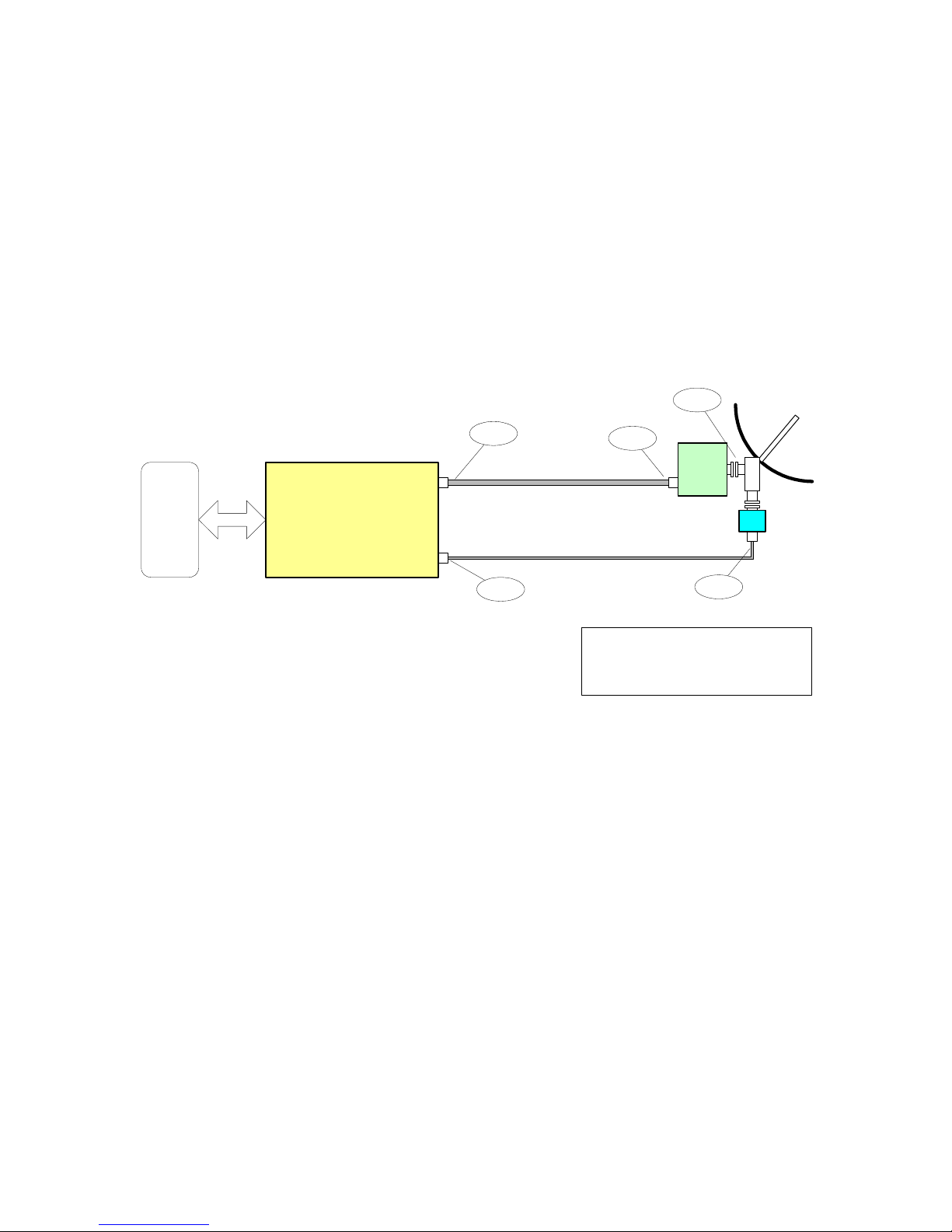
complexity of these items is changed. The basic station diagram below shows the typical
equipment complement for an L-Band based VSAT. The station can be expanded by adding
combiners and splitters in the IF to feed more modems.
Attempting to build a multi-modem L-Band station does bring up one of the difficulties of using an
L-Band IF Link. The power and reference signals to a BUC and LNB may have to be combined in
a separate BIAS-T/Mux device. This is because special combiners and splitters would be needed
to pass the current for the typical BUC or LNB. The lower cutoff frequency of a combiner or
splitter may not also pass a 10 MHz reference signal. A “Wilkinson” type combiner and splitter are
the types needed.
Page L-Band - 5
Page 6

L-Band IF Application Guide
DIN
M5 L-Band Modem
24V
DC
DTE
Transmit IF
10 MHz OCXO
Receive IF
Reference
Bias T / MUX
Bias T / MUX
13/18 V
DC
N
LMR-400 (25 - 200 ft)
F
N
RG6 (25 - 200 ft)
UC/PA
"BUC"
LNB
O
M
T
F
Typical VSAT Configuration
L-Band Version
MAB 8/12/02
This is not intended as a definitive guide to design of L-Band stations. Rather it is a list of
considerations and recommendations when putting together the equipment complement for a
station. Note also that the BUC and LNB usually require power and reference signals. The
voltages show on the diagram above are dependant on the particular equipment used. Some
BUCs require approximately 15 volts while others may use approximately 36 or 48 volts. Some
BUCs also use a reference frequency in the L-Band range instead of the more common 10 MHz.
3.1 Block UpConverter/ Power Amplifier Selection
A prospective BUC must meet certain minimum requirements:
• Minimum gain should be based on the required output power levels and cable losses. Most
modern BUCs seem to provide between 50 and 67 dB of gain, depending on power output.
The typical input power required for full power output varies between -20 and -30 dB.
• Maximum phase noise levels need to be determined based on the data rates being used.
• Frequency stability: Determined by externally applied 10 MHz reference oscillator. Typically
requires an approximate 1 part in 10
7
OCXO for C or Ku-Band operation. This represents a
possible 600 Hz error at 6 GHz or 1.4 kHz at 14 GHz transmit frequency.
• Input Connector: 50 Ohm, Type N or TNC
• Power Output: 1 to 20 Watts depending on satellite, location, antenna size, etc.
If the cable length between the modem and the BUC is very long then a higher voltage may be
desirable due to voltage drop in the cables.
3.2 LNB Selection
It is doubtful that one could use a TVRO video class LNB and make it work in a data application.
This is mainly because these LNBs were designed with a very wideband video carrier in mind,
and the phase noise performance is far from that necessary for a lower data rate PSK carrier.
Today, data grade LNBs are still fairly inexpensive, but a prospective LNB must meet certain
minimum requirements:
• Gain of approximately 45 to 70 dB
• Maximum phase noise levels need to be determined based on the data rates being used.
• Frequency stability: +/- 5 to +/- 25 kHz preferred, +/- 500 kHz acceptable if phase noise good.
Page L-Band - 6
Page 7

L-Band IF Application Guide
Caution: If the receive frequency stability exceeds the channel spacing then there
is the possibility of locking to adjacent similar carriers!
• LNB output Connector: 75 Ohm type “F” connector, while a Type “N” connector would be
preferable for reliable weather proofing. If type F is used insure that it is weather sealed.
3.3 Outdoor Equipment Power Provision
Block UpConverter Power. Current BUCs may require anywhere from approximately 12 VDC to –
48 VDC depending on the manufacturer. Approximately 50 Watts is not uncommon. The power is
typically applied via the transmit cable, and removed by the BUC for internal use. The PSM4900L contains an internal transmit Bias T/Mux to apply the power and reference signals to the
transmit line. See figure x for an example of this configuration
LNB Power. Most current data grade LNBs require approximately 15 to 24 VDC at 200 to 300
milli-Amps. The power is typically applied via the receive cable, and removed by the LNB for
internal use. The PSM-4900L contains an internal receive Bias T/Mux to apply the power and
reference signals to the receive line.
3.4 Station Reference
Most current BUCs require an external 10 MHz reference supplied on the cable which they
demultiplex and use to phase lock the Upconverter Local Oscillator. The two characteristics
required here are very good stability (an OCXO) and low phase noise. The BUC manufacturer
should specify the requirements, but it is not difficult to figure out some minimum capabilities.
First, to achieve an Intelsat specified transmit signal uncertainty of 50 Hz per 1 kbps. A C-Band
reference for a 32 kbps carrier would require approximately 2 parts in 10
is +/- 1200 Hz at 6 GHz transmit frequency. A Ku-Band BUC would require 1 part in 10
7
stability minimum. This
7
stability
for a 32 kbps data rate. Higher data rates would require less stability.
The typical BUC level requirement for the reference input is usually somewhere between +5 and
–3 or –5 dBm from a sine wave oscillator. The PSM-4900 output is nominally +3 dBm allowing for
significant cable loss at 10 MHz.
The reference oscillator phase noise is multiplied when phase locking the BUC Local Oscillator.
Thus the phase noise on the oscillator must be extremely low and probably cannot be viewed
directly on a spectrum analyzer. Its effect however will be visible on the BUC output with a known
clean carrier input.
3.5 Safety and Lightning Protection
The block diagram shown above does not incude any provisions for lightning arrestors or
protections devices. The typical “spark gap” type of receive line device, providing a connection for
a line to the station earth ground is probably suitable for the receive side. Similar devices used on
the transmit side must be able to handle up to approximately 5 or 6 Amps to allow for the BUC
current. Many common devices are termed “quarter wave” arrestors and should NOT be used.
These are narrow band devices which contain a direct short to ground. Gas discharge type
arrestors are probably suitable. Local electrical codes should be checked to insure compliance.
It is very important to securely ground the antenna structure directly to a good low impedance
earth ground connection.
3.5.1 BUC Power Safety
With the inclusion of the BUC power supply on the transmit IF cable comes several safety
concerns:
• First, the BUC power should not be enabled via the modem until the cabling is
completely installed. Danger to both personnel and equipment is possible when
Page L-Band - 7
Page 8
L-Band IF Application Guide
handling the exposed end of the transmit cable with power applied. Any BUC
voltage represents a possible shock hazard, especially at higher voltages.
• Second, when DC power is applied extreme care should be used with test
equipment. Many spectrum analyzers and power meters could be seriously
damaged by the application of DC to their inputs. A “DC Block” is a good safety
measure on equipment input.
• Third, many common devices can be damaged by the application of DC power. For
example attenuators, directional couplers and combiners could be destroyed, and
at least cause the BUC to not work due to loss of power. This includes attenuators,
etc. that may be used to form an external test IF loob-back
3.6 Station Gain Budgets
Below is a block and level diagram of a typical station showing some example levels of relevant
signals in the transmit and receive chain.
+32 dBm
DTE
M5 L-Band Modem
Transmit IF
Receive IF
-13 dBm
N
F
-65 dBm
LMR-400 (200 ft)
-25 dBm
RG6 (200 ft)
N
UC/PA
"BUC"
G=57 dB
-45 dBm
LNB
O
M
T
F
Example VSAT Signal Levels
L-Band Version
MAB 8/12/02
There is virtually no control over the receive signal levels short of setting the antenna size. The
demodulator uses a sliding AGC window with an approximate AGC range of 55 dB at any given
data rate. As the data rate is decreased the AGC window moves down to accommodate the
decreasing signal level.
The transmit levels must be carefully controlled however. Most BUCs have no internal gain
control and therefore represent a fixed gain block. The output power is thus directly proportional
to the input level. The exception is notable however. If the amplifier is driven to its 1 dB
compression point and beyond the output level no longer increases. Some types of amplifiers
(like TWTs) will actually result in a lower output level as the input is increased. What is important
therefore is to know the maximum input level of the BUC, or the gain and Pout at the 1 dB
compression point. The maximum modem transmit output level is then computed based on the
BUC’s Pin max minus the transmit cable loss. The levels shown above assume a transmit cable
loss of about 12 dB.
3.7 Cable Selection
Knowing what approximate levels are required at each point in the station block diagram permits
specification of required cable size and type. Several other factors enter here:
1. The transmit cable must also carry a heavy current on the order of 1 to 5 Amps to power
the BUC/PA combination. The DC resistance and cable voltage drop must allow this gear
Page L-Band - 8
Page 9

L-Band IF Application Guide
to receive their minimum voltage plus enough margin for variation with time and
temperature.
2. At L-Band frequencies the loss variation with temperature can be extreme. For example a
200 foot length of RG214 cable (double shielded, ½ inch class) has approximately 20 dB
of loss and a variation vs. Temperature of 0.2% (of dB) per degree Centigrade. If
operating in an exposed environment (like a desert) where the temperature may vary
approximately 20 deg. C from day to night that could represent a variation of almost 1 dB
over a 12 hour period. In a 20 dB loss cable the attenuation change is then approximately
.04 dB per deg. C, or 0.8 dB over the full 20 deg. C change. First, this probably says that
the cables must be either buried in conduit or shielded from the sun if run on a cable rack
to minimize variations. A better quality cable such as Times LMR-400 cable would also
provide a significant improvement.
Note: Temperature variation on SCPC links can easily be remedied by using the
AUPC option available for the PSM-4900 modems.
3. The transmit and receive cables must be separated and definitely not tied directly
together with “tie-wraps”, especially on longer runs. This is because of the tremendous
difference between the transmit and receive levels possible. This is made worse on long
cable runs because the modem end will have higher transmit levels and the receive will
have lower levels than on a short run. The better cables in this regard have double
shielding (two braids or a braid/foil combination) and a shielding efficiency of 100 dB or
better. A good note here is that with the typical LO frequencies as shown in the example
above, the transmit and receive L-Band frequencies are widely separated. If the signals
were within the LNB stability/drift frequency limits there might be a tendency for the
receive to attempt locking to its own transmit signal.
4. Considering the L-Band IF range is 800 MHz or more spanning close to an octave, the
variation in loss between the high and low ends of the IF range may be significant.
A nominal design point may be to allow for 10 to 15 dB of total cable losses and select cable that
will reliably achieve this. A more accurate “rule of thumb” would be to design for a total gain from
the antenna to modem receive input of 40 dB. For example if the receive LNB has a gain of 60 dB
and there are no other losses then the cable can have a maximum loss of 20 dB (60 – 40 dB). In
formula form this is:
Loss(cable max) = Gain(LNB) – 40 – Loss(misc) in dB
Or for the transmit side the cable loss should not keep the input to the BUC from reaching its
Power input for 1 dB compression point Arbitrarily allowing a 3 dB margin in the modem output,
this formula would be:
Loss(cable max) = +2 – BUC Pin(1dB) – Loss(misc) in dB
Notice that we are assuming no miscellaneous losses in the transmit or receive side, but there
may be other losses such as a splitter or output sample port used.
Trying to buy too cheap a cable will only result in problems that are more expensive to fix than
using the proper cable to begin with. Remember that the L-Band design allows for moderately
inexpensive cable in exchange, especially as compared to the typical requirement for either
expensive outdoor converters or very expensive heliax / waveguide with indoor converters.
The PSM-4900L provides a Type “N” 50 Ohm impedance on its transmit cable and a Type “F”, 75
Ohm receive cable connection. Most BUCs are also 50 Ohm, while most LNBs provide a 75 Ohm
impedance and use Type “F” connectors.
Several cable types are shown below with typical maximum recommended frequency, size,
losses per 100 feet at 1.2 GHz, shielding efficiency, and relative approximate costs per foot.
Recommended cables are shown with asterisks. Since maximum loss is preferred to be 20 dB or
Page L-Band - 9
Page 10

L-Band IF Application Guide
less, then generally the cable size is chosen to keep the cable loss well below that point. 10 to 15
dB is probably a better design guide considering that other connection losses are inevitable. DC
resistance for the transmit cable should also be considered with respect to BUC current
draw/voltage drop. Also consider that in areas where temperature change is high a lower loss
cable should be chosen to minimize absolute transmit power variation.
Typical Coaxial Cable Characteristics
Cable Type Max. Freq.
(MHz)
RG58 (50Ω) 1,000 .19 21 70 $0.39
RG59 (75Ω) 1,000 .25 18 70 0.39
RG6 (75Ω) 2,200 .25 10 >90 0.89
RG11 (75Ω) 2,200 .405 5 >90 0.89
Times LMR-240 (50Ω) 5,000 .24 9.2 >90 0.47
Times LMR-300 (50Ω) 5,000 .30 6.8 >90 0.53
Times LMR-400 (50Ω) 5,000 .405 4.8 >90 0.64
Belden 9913 (50Ω) 5,000 .405 5.2 >90 0.60
Times LMR-600 (50Ω) 5,000 .59 3.1 >90 1.30
RG214 (50Ω) 5,000 .405 10.1 >90 1.70
3/8”LDF (50Ω) 5,000 .44 4.1 >90 1.89
1/2”Superflex (50Ω) 5,000 .52 4.2 >90 1.89
Note that the common RG214 type cable is not only more expensive, but also higher loss than
several other available cable types. The maximum length that RG214 would be used assuming
the approx 15 dB loss criteria would be 150 ft or 50 meters. Times LMR-400 cable would be
usable over 300 ft. At less cost. Both of these examples assume that the DC loss of the BUC
power is within tolerance. For many receive applications RG6 cable is a good choice.
The typical DC resistance of 0.405 inch class 50 Ohm cables such as RG214 or LMR-400 is
approximately 0.3 Ohms per 100 feet including both the center conductor and sheild. Thus at a
250 foot run the total resistance is 1 Ohm, which is a 1 Volt drop per Amp of BUC current draw. It
would be reasonable to then assume an approximate 2 Volt drop in the DC Voltage available at
the BUC input ( 22 Volts for a 24 Volt supply at the modem).
O.D. (in.) Loss/100
feet (dB)
@ 1.2 GHz
Shielding
Efficiency
(dB)
Estimated
Cost/ft.
(USD)
4.0 Interoperability Between 70 MHz and L-Band Modems
Not only is the design and operation of the PSM-4900L modem closely based on that of the PSM4900 70 MHz modem, but the units are fully interoperable. Thus a typical system configuration
with one or more “Hub” stations utilizing 70 MHz as the IF and many remotes utilizing both 70
MHz and L-Band equipments works well without consideration to the particular equipment at any
site. New sites in an existing system may be added using either L-Band or 70 MHz as the IF link
frequency.
5.0 Specifications
The specifications for the PSM-4900L are shown below.
Page L-Band - 10
Page 11

L-Band IF Application Guide
SPECIFICATIONS
Parameter PSM-4900L
Operating Modes, all programmable: Receive and Transmit Continuous (SCPC), Optional Tx Burst.
Transmit IF Frequency Range:
Receive IF Frequency Range:
Transmit Output Power: (50 Ω Type N)
Return Loss
Transmit Output Phase Noise: Better than IESS-308/309 by 6 dB typical, 4 dB minimum.
Transmit Output Level Stability/Accuracy: ±0.5 dB, 0 ~ 50°C, accurate ±0.5 dB, 950 ~ 1750 MHz at 25°C
Transmit Output Level Spurious/Harmonics: <-50 dBc / <-50 dBc up to -10 dBm, <-40 dBc @ + 5 dBm out
Receive Carrier Level In (75 Ω Type F):
Return Loss
Maximum Composite Receive Input Power -5 dBm or +40 dBc whichever is lower power
Receive Demodulator Phase Noise: Better than IESS-308/309 by 4 dB minimum., 6 dB typical.
Receive Acquisition Range:
Transmit BUC Power: (via DIN plug on rear).
Voltage and Current monitor at Front Panel.
Transmit BUC Reference:(can be disabled).
Receive LNB Power: (can be disabled).
Current monitor at Front Panel.
Receive LNB Reference: (can be disabled).
Frequency Reference (Internal) Stability/Aging
Reference Phase Noise
External:
Modulation and Demodulation: Programmable for BPSK or QPSK independently
Forward Error Correction:
Optional Turbo Product Codes:
Optional Concatenated Reed-Solomon:
FEC (Viterbi or TPC) Rates Selectable: 1/2, 3/4 or 7/8
Data Rates Programmable at FEC rate 1/2:
(without IBS mux or R-S option)
Data Rates Programmable at FEC rate 3/4 or 7/8 (without
IBS mux or R-S option)
IBS Multiplex Option: IBS framing supporting enhanced buffered RS-232/485 overhead
Data Rate Selection: Transmit & Receive: Programmable in 1bps increments. Accurate to 2 x 10E-12
Receive Data FIFO Buffer:
Plesiochronous or Doppler Elastic Store
Data Interface (All synchronous) RS-449/422 or V.35 or EIA-530 or RS-232 electronically selectable
BER Performance: with Viterbi FEC ½ rate:
½ rate Viterbi +R-S Concatenated FEC:
¾ rate Viterbi +R-S Concatenated FEC:
½ rate Turbo Product Codes FEC:
¾ rate Turbo Product Codes FEC:
Fast Receive Lock Performance at FEC rate ½, 6.0 dB
Eb/No, +/-30kHz acquisition range: (Average)
Front Panel Control: LCD display and keypad provide full status and programmability.
Remote Control: Terminal Mode:
Packet Mode:
Case Dimensions: Rack mount @ 1 RU (19"W X 14"D X 1.75"H.)
Input Power Requirements (without BUC): 90 to 264 VAC, 50/60 HZ, Approx. 40 Watts, 60 Watts maximum,
Operating Conditions:
950 to 1750 MHz in 1 Hz Steps.
950 to 1900 MHz in 1 Hz Steps.
+5 to -35 dBm, programmable in 0.1 dB steps
14 dB typical, 10 dB minimum.
-20 to -70 dBm, scales to –101 at lower data rates.
Formula is: minimum = 10log(symbol rate)-135dBm
10 dB minimum.
Programmable from ± 100 Hz to ± 1.25 MHz
Nominal 24VDC, 95 Watts (Or 12/36/48 VDC). Maximum 60 Vdc /
6 A, up to 250 W. Max/Min V and current alarms limits settable.
10 MHz at nominal +3 dBm from internal or external reference.
Selectable +13/+18 VDC at <500mA.
Max/Min current alarms limits settable.
10 MHz at nominal -3 dBm internal or external reference.
1 x 10 -7 OCXO. 2 x 10 -7/year aging.
-110 dBc at 10 Hz
-130 dBc at 100 Hz
-140 dBc at 1 kHz
-150 dBc at 10 kHz
-155 dBc at 100 kHz
External reference input on rear panel for 1, 5, 9, or 10 MHz.
Internal OCXO phase locks to external input.
Viterbi. k=7
Rates 1/2, 3/4 or 7/8. Standard and Short Block.
n=126, k=112, t=7 or n=219, k=201,t=9 or programmable with
depth of 4 or 8
1.2 kbps to 1,230 kbps BPSK,
2.4 kbps to 2,460 kbps QPSK
2.4 kbps to 2,460 kbps BPSK,
4.8 kbps to 4,920 kbps QPSK
channel, AUPC, remote modem control and variable overhead.
(relative to reference).
4 bits to 131,070 bits, programmable in 1 bit increments, or in
delay time.
at DB-37 connector. DB25 and V.35 (M34) adaptors available.
10-7 at 6.0 dB Eb/No, 10-5 at 4.8 dB
10-7 at 3.7 dB, 3.5 dB typical (n=126, k=112)
10-7 at 4.7 dB, 4.5 dB typical
10-7 at 3.0 dB, 2.8 dB typical
10-7 at 3.7 dB, 3.5 dB typical
315 msecond at 9.6 kbps QPSK or
175 msecond at 9.6 kbps BPSK .
71 msecond at 64 kbps.QPSK
Full screen live display and interactive control of all operating
parameters and status.
Command packet driven RS-232/485/IrDA control and reporting of
all parameters and status.
fully loaded including LNB power.
0 to 50° C, to 95% humidity, non-condensing.
Page L-Band - 11
Page 12

L-Band IF Application Guide
6.0 Command and Control Protocol
The command and control protocol for the PSM-4900L is virtually identical to that for the PSM4900 70MHz IF unit. There are two new commands” shown below. The first new command
controls the BUC and the second controls the LNB.
In addition to the two new commands shown below the normal tranmsit and receive IF commands
now use 2 bytes unused in the standard unit. These two bytes extend the normal 4 byte binary
frequency number to 6 bytes.
WARNING: It may be difficult in many programming languages to generate a 6
byte number representation for binary programming of the modem.
Like the front panel controls, the remote control procedures for specifying transmit and receive IF
frequencies are dependant upon wether a BUC and/or LNB LO frequency has been supplied. If a
non-zero frequency has been input from any source then the transmit and receive frequency
becomes the RF operating frequency as described in section 2.1, “IF Frequency Range”. This
property is independent for the transmit and receive paths.
Note that the few changes relative to the standard 70 MHz unit makes it easy to use a single
monitor and control systems to talk to both modem types.
Page L-Band - 12
Page 13
L-Band IF Application Guide
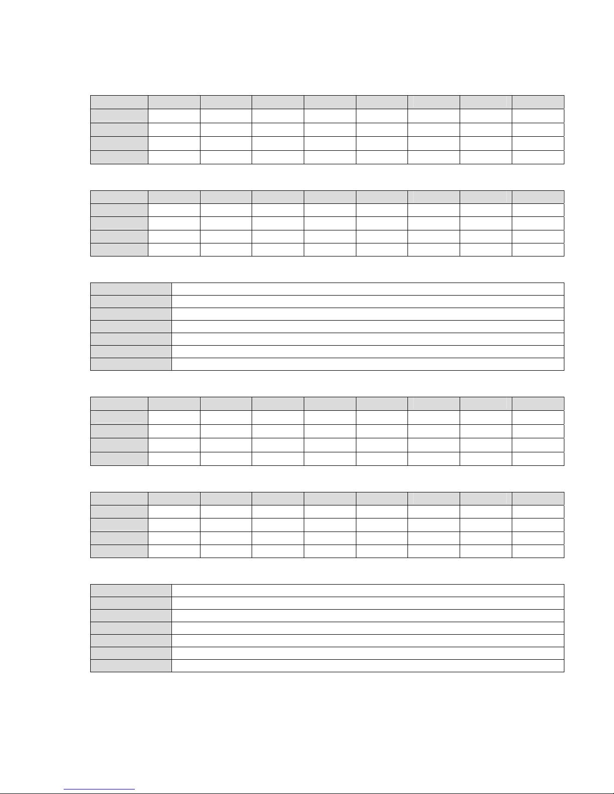
Mod BUC, Command [47h], Read Change Flags (L-Band Only)
Bit 0 Bit 1 Bit 2 Bit 3 Bit 4 Bit 5 Bit 6 Bit 7
Byte 0 BucPwr VOut VMin IOut IMax IMin Ref LoFrq
Byte 1 Spare Spare Spare Spare Spare Spare Spare Spare
Byte 2 Spare Spare Spare Spare Spare Spare Spare Spare
Byte 3 Spare Spare Spare Spare Spare Spare Spare Spare
Mod BUC, Read Flags
Bit 0 Bit 1 Bit 2 Bit 3 Bit 4 Bit 5 Bit 6 Bit 7
Byte 4 PwrEn0 PwrEn1 PwrEn2 RefEn0 RefEn1 RefEn2 Spare Spare
Byte 5 Spare Spare Spare Spare Spare Spare Spare Spare
Byte 6 Spare Spare Spare Spare Spare Spare Spare Spare
Byte 7 Spare Spare Spare Spare Spare Spare Spare Spare
Mod BUC, Read Bytes
Bytes 8-9 BUC Voltage Out, Signed 16b, (0 to >600), 100mV Increments
Bytes 10-11 BUC Voltage Min, Signed 16b, (80 to 600), 100mV Increments
Bytes 12-13 BUC Current Out, Signed 16b, (0 to >600), 10mA Increments
Bytes 14-15 BUC Current Max, Signed 16b, (5 to 600), 10mA Increments
Bytes 16-17 BUC Current Min, Signed 16b, (5 to 600), 10mA Increments
Bytes 18-23 BUC LO Frequency, Unsigned 48b, (0 to 50,000,000,000), 1Hz Increments
Bytes 24-33 Spare
Mod BUC, Write Enable Flags
Bit 0 Bit 1 Bit 2 Bit 3 Bit 4 Bit 5 Bit 6 Bit 7
Byte 0 BucPwr 0 VMin 0 IMax IMin Ref LoFrq
Byte 1 0 0 0 0 0 0 0 0
Byte 2 0 0 0 0 0 0 0 0
Byte 3 0 0 0 0 0 0 0 0
Mod BUC, Write Flags
Bit 0 Bit 1 Bit 2 Bit 3 Bit 4 Bit 5 Bit 6 Bit 7
Byte 4 PwrEn0 PwrEn1 PwrEn2 RefEn0 RefEn1 RefEn2 Spare Spare
Byte 5 Spare Spare Spare Spare Spare Spare Spare Spare
Byte 6 Spare Spare Spare Spare Spare Spare Spare Spare
Byte 7 Spare Spare Spare Spare Spare Spare Spare Spare
Mod BUC, Write Bytes
Bytes 8-9 x
Bytes 10-11 BUC Voltage Min, Signed 16b, (80 to 600), 100mV Increments
Bytes 12-13 x
Bytes 14-15 BUC Current Max, Signed 16b, (5 to 600), 10mA Increments
Bytes 16-17 BUC Current Min, Signed 16b, (5 to 600), 10mA Increments
Bytes 18-23 BUC LO Frequency, Unsigned 48b, (0 to 50,000,000,000), 1Hz Increments
Bytes 24-33 Spare
[PwrEn2-PwrEn0] = BUC Power, 3b, 0=Disabled, 1=Enabled
[RefEn2-RefEn0] = BUC 10MHz Ref, 3b, 0=Disabled, 1=Enabled
Page L-Band - 13
Page 14

L-Band IF Application Guide
Demod LNB, Command [87h], Read Change Flags (Hybrid & L-Band Only)
Bit 0 Bit 1 Bit 2 Bit 3 Bit 4 Bit 5 Bit 6 Bit 7
Byte 0 LnbPwr Reserved Reserved IOut IMax IMin Ref LoFrq
Byte 1 Spare Spare Spare Spare Spare Spare Spare Spare
Byte 2 Spare Spare Spare Spare Spare Spare Spare Spare
Byte 3 Spare Spare Spare Spare Spare Spare Spare Spare
Demod LNB, Read Flags
Bit 0 Bit 1 Bit 2 Bit 3 Bit 4 Bit 5 Bit 6 Bit 7
Byte 4 PwrEn0 PwrEn1 PwrEn2 RefEn0 RefEn1 RefEn2 Spare Spare
Byte 5 Spare Spare Spare Spare Spare Spare Spare Spare
Byte 6 Spare Spare Spare Spare Spare Spare Spare Spare
Byte 7 Spare Spare Spare Spare Spare Spare Spare Spare
Demod LNB, Read Bytes
Bytes 8-9 Reserved
Bytes 10-11 Reserved
Bytes 12-13 LNB Current Out, Signed 16b, (0 to >500), 1mA Increments
Bytes 14-15 LNB Current Max, Signed 16b, (5 to 500), 1mA Increments
Bytes 16-17 LNB Current Min, Signed 16b, (5 to 500), 1mA Increments
Bytes 18-23 LNB LO Frequency, Unsigned 48b, (0 to 50,000,000,000), 1Hz Increments
Bytes 24-33 Spare
Demod LNB, Write Enable Flags
Bit 0 Bit 1 Bit 2 Bit 3 Bit 4 Bit 5 Bit 6 Bit 7
Byte 0 BucPwr 0 0 0 IMax IMin Ref LoFrq
Byte 1 0 0 0 0 0 0 0 0
Byte 2 0 0 0 0 0 0 0 0
Byte 3 0 0 0 0 0 0 0 0
Demod LNB, Write Flags
Bit 0 Bit 1 Bit 2 Bit 3 Bit 4 Bit 5 Bit 6 Bit 7
Byte 4 PwrEn0 PwrEn1 PwrEn2 RefEn0 RefEn1 RefEn2 Spare Spare
Byte 5 Spare Spare Spare Spare Spare Spare Spare Spare
Byte 6 Spare Spare Spare Spare Spare Spare Spare Spare
Byte 7 Spare Spare Spare Spare Spare Spare Spare Spare
Demod LNB, Write Bytes
Bytes 8-9 X
Bytes 10-11 X
Bytes 12-13 X
Bytes 14-15 LNB Current Max, Signed 16b, (5 to 500), 1mA Increments
Bytes 16-17 LNB Current Min, Signed 16b, (5 to 500), 1mA Increments
Bytes 18-23 LNB LO Frequency, Unsigned 48b, (0 to 50,000,000,000), 1Hz Increments
Bytes 24-33 Spare
[PwrEn2-PwrEn0] = LNB Power, 3b, 0=Disabled, 1=Enabled
[RefEn2-RefEn0] = LNB 10MHz Ref, 3b, 0=Disabled , 1 = Enabled
Page L-Band - 14
 Loading...