

DATUM ELECTRONICS M425 Handbook & Installation Manual
DATUM ELECTRONICS
M425 TORQUE TRANSDUCER
HANDBOOK AND INSTALLATION GUIDE
DATUM ELECTRONICS LIMITED TELEPHONE: +44 (0) 1983 28 28 34 FAX: +44 (0) 1983 28 28 35 EMAIL: support@datum-electronics.co.uk WEB: www.datum-electronics.co.uk

DATUM ELECTRONICS M425 TORQUE TRANSDUCER HANDBOOK
2
CONTENTS
M425 INTRODUCTION 3
What is it designed to do? 3
SYSTEM ADVANTAGES 3
M425 system performance and benefit: 3
SYSTEM OUTLINE 3
The key features of the M425 system 3
System items supplied 3
Check list 3
Included as standard with the M425 3
Optional extras available from Datum Electronics 3
FAMILIARISATION 4
Simple diagnostics, testing and connection 4
MECHANICAL INSTALLATION 5
Objective of the mounting 5
Things to avoid 5
Which way round to mount? 6
Keyway fit size 6
Anti-rotation point 6
ELECTRICAL CONNECTION 7
Cable and socket connectors wiring guide 7
SYSTEM DIAGRAM 8
USER INTERFACES 9
Universal interface 9
Graphic user interface 9
Versatile bulkhead mounted indicator 10
Alternate connection options 10
DATA OUTPUT 11
The M425 Transducer - 3 operational modes 11
Data output format 11
Raw data torque calculation 11
Software commands direct to the M425 stator 11
How checksum is calculated 12
Sample rates and resolution 12
PC port limitations 12
OUTPUT PERFORMANCE 13
Maximum sample rates 13
OUTPUT DATA 14
Read more from your data 14
SPECIFICATIONS 15
M425 performance information 15
M425 shaft stiffness and load parameters 16
M425 mass and dimensions (mm) 17
PRE-CALIBRATED AND TESTED 18
Test certificate 18
ALTERNATIVE SOLUTIONS 18
The Datum RS & FF425 ranges 18
DIAGNOSTICS 19
Guide to status codes 19
MAINTENANCE 20
Serviceable items: Bearings 20
GLOSSARY OF TERMS 20
Document: 1010 Issue: 1 Date: 17/2/2014
DATUM ELECTRONICS M425 TORQUE TRANSDUCER HANDBOOK
3
SYSTEM OUTLINE
The key features of the M425 system are:
SYSTEM ADVANTAGES
M425 system performance and benefits:
M425 INTRODUCTION
What is it designed to do?
The latest technology Datum Electronics Series M425
non-contact rotary Torque Transducers have been designed
to fit with most applications and solutions requiring rotary
torque measurement. The Torque Transducer fits in line with
the drive train or test bed, using standard keyway shafts.
A non-contact transmission system provides data directly
proportional to torque. In this variant it is supplied as a
complete transducer with bearings to support the stator unit
on the rotating shaft. It is suitable for most general test rig
applications.
The M425 Torque Transducer utilises a strain gauged shaft
for accurate and reliable torque measurement and a set
of rotating on-shaft conditioning electronics. The digital
signals are transmitted to the non-rotating part of the system
or stator providing a reliable and highly accurate torque
measurement solution.
The M425 has a torque measuring element design with an
optimum length to maximise overall accuracy and give a high
degree of tolerance to mounting offset.
The M425 also has a legacy mode so that it can be used as a
direct replacement for the previous M420 Transducer.
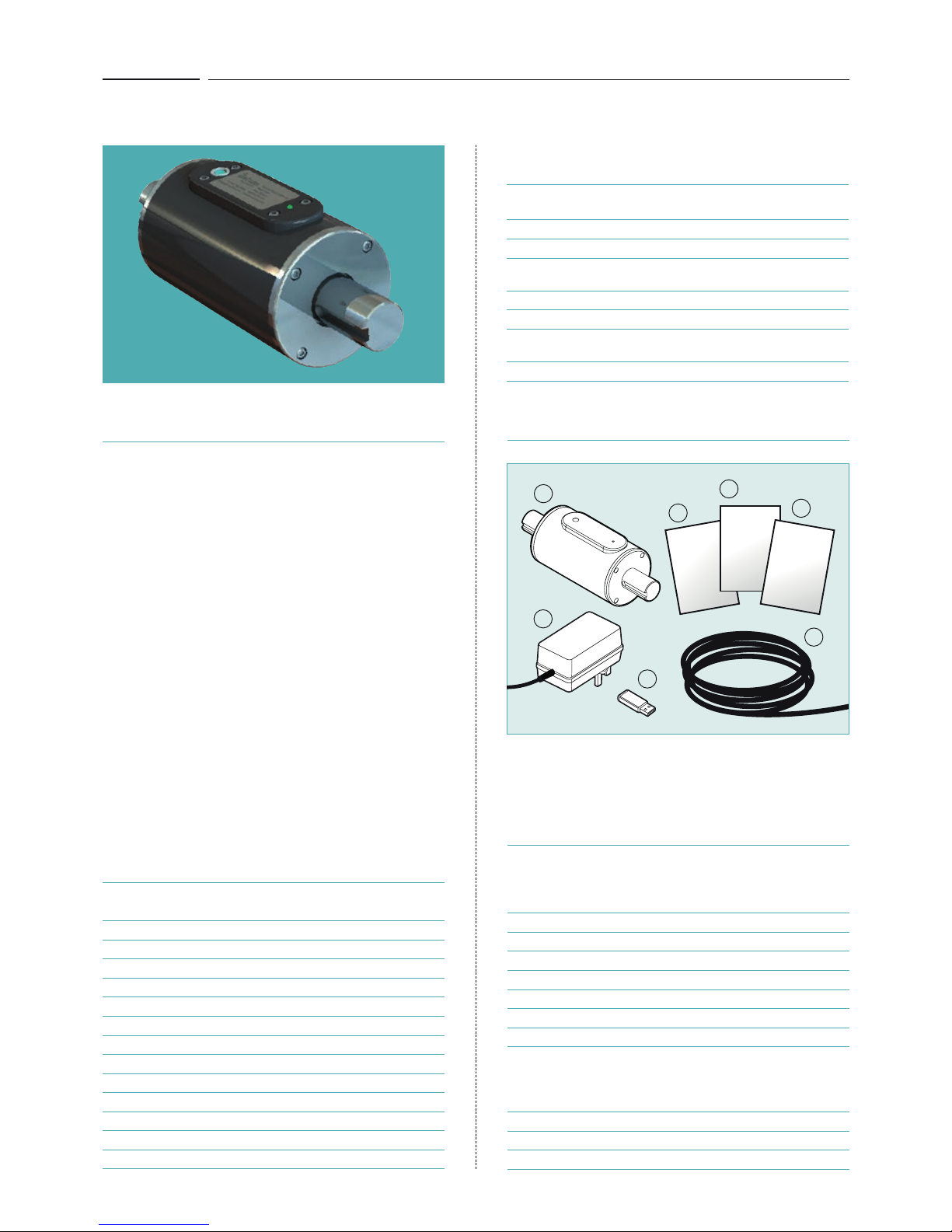
CHECK LIST
Included as standard with the M425 Torque
Transducer:
DESCRIPTION QUANTITY
1 - M425 Torque Transducer 1
2 - M425 handbook 1
3 - Quick-start guide 1
4 - Test certificate 1
5 - Datum software 1
6 - Transducer cable 1
7 - Power supply 1
Optional extras available from Datum Electronics:
DESCRIPTION
Universal Interface
Versatile bulkhead mounted indicator
M425 Transducer to universal interface data cable
SYSTEM ITEMS SUPPLIED
It is recommended that all hardware, consumables, tools and
software are checked and present before preparation and
installation commences.
5
1
2
4
3
M425
Handbook
Quick-Start
Guide
Test
Certificate
Accuracy and resolution options
High data rate
Static and rotary torque measurement
Operational stability
Non-contact data transmission
Magnetic speed sensor - not effected by dirt
Simple to integrate
Robust construction
Torque transducer sensor
Ranges 0-5Nm up to 0-60,000Nm
High resolution torque sampling
Sample rate selection 1-4000 samples per second
Low power consumption
Complete torque transducer
Designed to be mounted in line with the drivetrain
Torque transducer body supported on rotary shaft
with bearings
Ideal for test rig applications
Keyway shaft for easy fit and rig design
Torque measurement available up to 60,000Nm
in a range of model sizes
Analogue output options
7
6
DATUM ELECTRONICS M425 TORQUE TRANSDUCER HANDBOOK
4
FAMILIARISATION
SIMPLE DIAGNOSTICS, TESTING
AND CONNECTION
Before installing your M425 Transducer into the rig or
machine we would advise you to familiarise yourself with its
connections and operation by performing a bench test.
By connecting the Transducer directly to a Datum Universal
Interface (example A below), or to a PC via the Datum
Universal Interface (example B opposite), you will be able
to rotate the shaft to generate an output signal of RPM. By
applying a small torque by hand to the shaft you will also
be able see the change in the torque signal output on the
Universal Interface display or in the Datum Data Logging
PC software.
If you are connecting to a PC without a Datum Universal
Interface and using your own instrumentation (example C
opposite) you will be able to test your instrumentation in the
same way by simulating a signal to the interface or indicator
model you are using. The M425 supports a variety of
universal interface models.
Once you are familiar with the transducer and its outputs
continue to install as normal. If any questions arise at this
stage please call our product support team for advice.
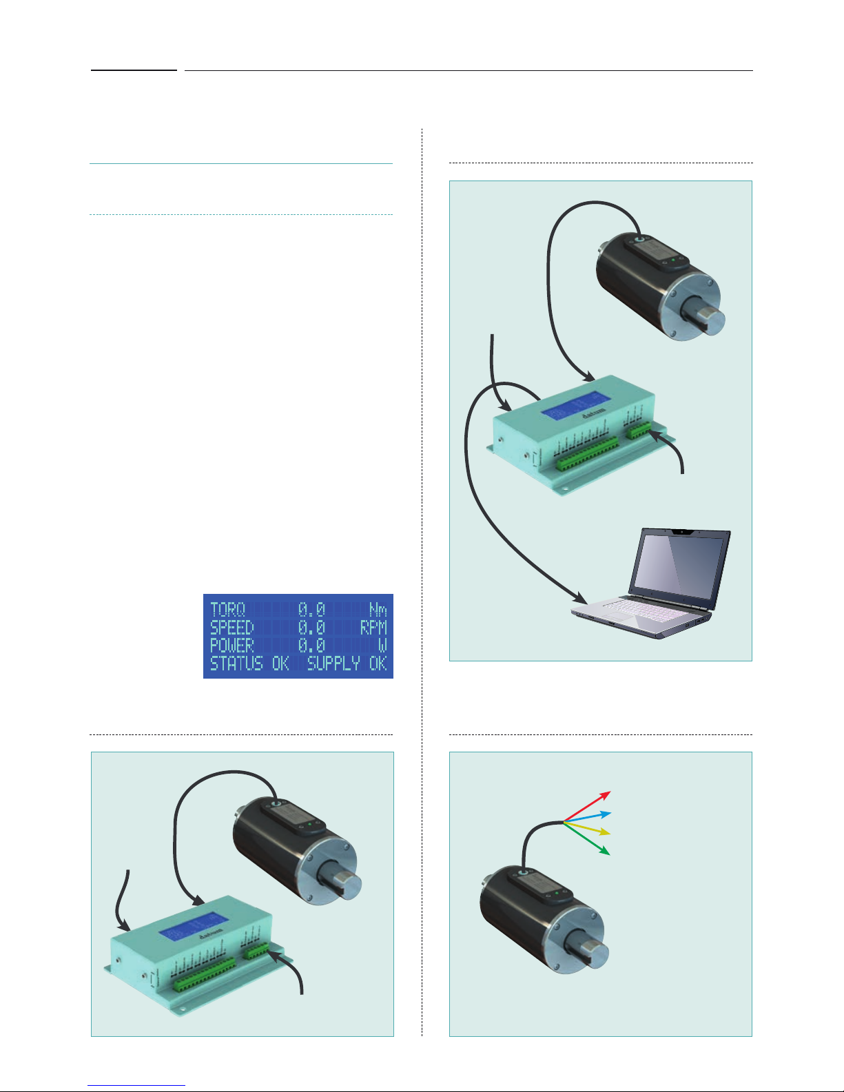
The Datum Universal Interface display
The Datum Universal Interface has a built-in display which
you can use for familiarisation with a direct connection to the
M425 Torque Transducer (diagram A below).
Connection example (A)
M425 to the Datum Universal Interface.
Connection example (B)
M425 to PC via the Datum Universal Interface.
Connection example (C)
Direct connection from M425 to an alternative
interface or indicator.
See electrical connection guide on page 7 for further
information on connecting your own instrumentation.
+12Vdc supply
Supply ground
RS485 A: -ve data
RS485 B: +ve data
RS232 TX/RX (option)
Diagram No. 3Diagram No. 1
Ethernet/USB
Diagram No. 2
M425
PC
M425
M425
Universal
Interface
Universal
Interface
Main power
input
Optional power supply:
15-24V dc 500mA
Main power
plug input
Optional power supply:
15-24V dc 500mA
The Universal
Interface display can
show the following
data from the M425
Torque Transducer:
DATUM ELECTRONICS M425 TORQUE TRANSDUCER HANDBOOK
5
MECHANICAL
INSTALLATION
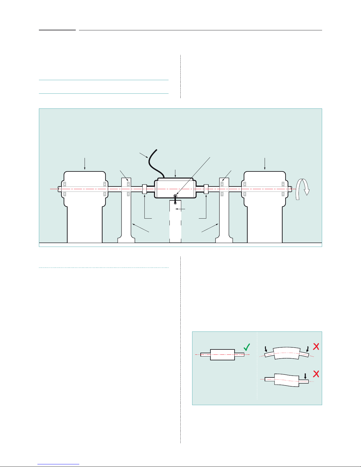
OBJECTIVE OF THE MOUNTING
The objective is to align the shaft of the M425
Torque Transducer (sensor) with the torque.
The torque should where possible be driven
through the centre line of the shaft.
Unlike Disk Transducers that require very fine alignment
tolerances when mounting, the M425’s longer shaft allows
a greater degree of flexibility in terms of alignment.
M425 Torque
Transducer
Anti-rotation
point
Securing
post
Load pumpEngine
Bearing Bearing
Keyway couplings
Plummer blocks
or suported bearings
Data output
cable
Typical installation with bearing block each side
THINGS TO AVOID
Overload = 150% the rating of the transducer. Loads at this
level should be avoided as they will decrease the fatigue life
of the Transducer. If you are likely to see large overloads at
the same time as wishing to see high resolution data for much
smaller torques please consult our sales team.
Ultimate Load = at the ultimate loads quoted for the
Transducer shaft (see table 8, page 16) the sensing element
will be damaged and large offsets will occur. At this level
the shaft will be well beyond its design limits and may
mechanically fail. If you have loaded a Transducer above
the Proof Load/Overload level it should be checked before
continued use.
Diagram No. 4
The series M425 Torque Transducers are designed
to withstand a level of overload.
The load levels quoted within tolerances (see table 8 on
page 16) should not have any effect on the calibration or
zero setting of the Transducers. Each Transducer has been
subjected to the proof load level within its testing cycle.
Loading the Transducer above the proof level will offset the
Transducer zero and will damage the Transducer. Regular
loading beyond the proof level will start to show progressive
zero movement and may effect both the gain and the
hysteresis of the Transducer. The shaft absolute load is the
maximum before the shaft will yield.
You should avoid any side loads or bending loads across
the shaft. As the M425 Transducer series have relatively
long shafts they are more tolerant to a small degree of
misalignment than short flange transducers (sensors), however
misalignment can change the loading on the internal bearings
of the device and should be avoided where possible.
Consider large dynamic or transient torques when
designing your test system.
When designing the test rig or test system that will use the
M425 Transducer you should consider the effect of any large
inertial / kinetic loads such as flywheels or brakes. If the
system is to drive to a high level of torque, and then a brake is
applied, the dynamic torque in the test rig can be much higher
than that of the output of the drive motor. The fast deceleration
torque may exceed the limits above causing damage.
Bent shaft
Offset shaft
Centre line shaft alignment
Diagram No. 5
Correct alignment indicated
above with the load running
through the centre of the shaft.
Avoid misalignment and side
loads or bending loads as
indicated on the right.
Where the installation will see a larger degree of misalignment
you should consider the use of flexible couplings in the
drive line. If misalignment is very likely consider the Datum
Electronics RS and FF ranges which are bearing-less
transducers (see page 18). Talk with our sales team who can
advise on this type of installation.
DATUM ELECTRONICS M425 TORQUE TRANSDUCER HANDBOOK
6
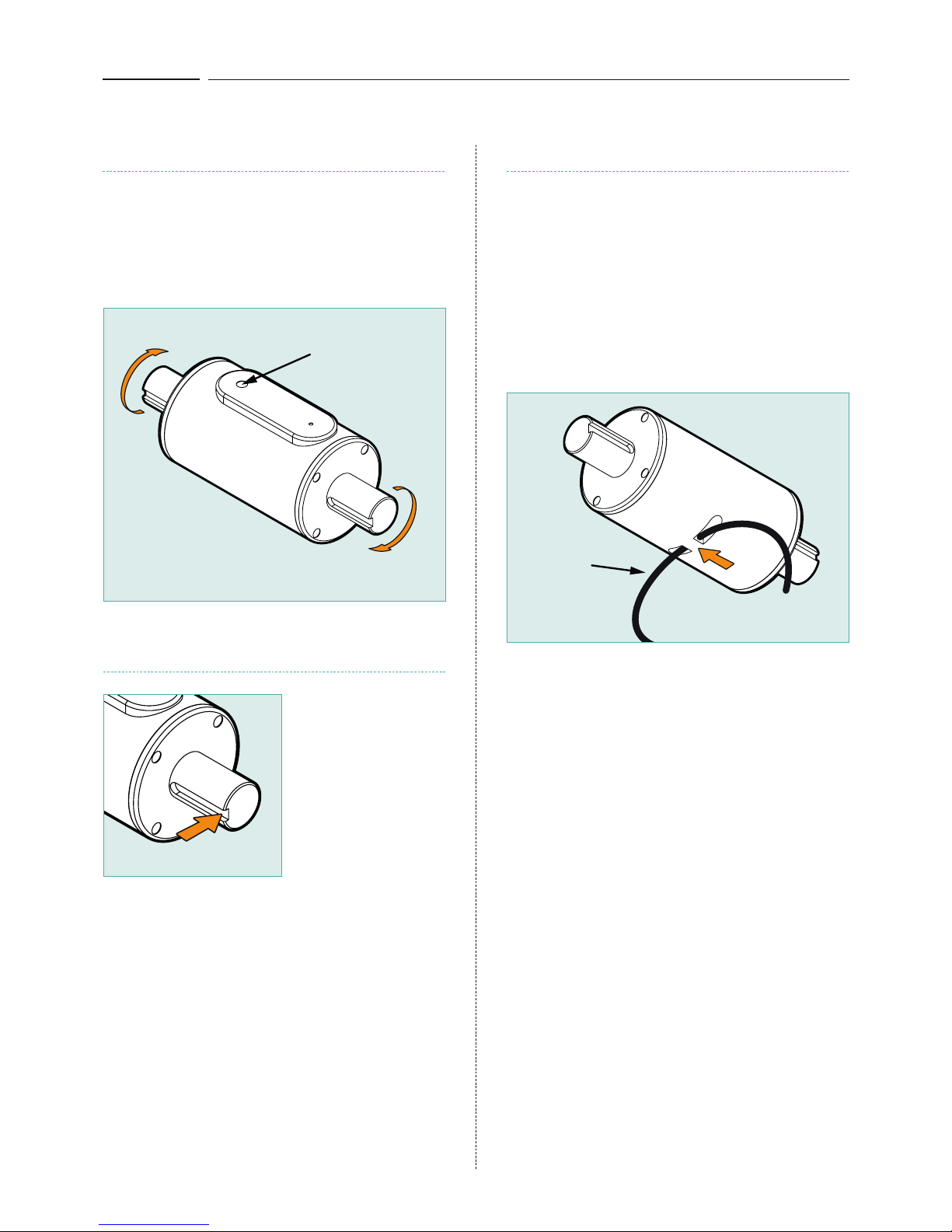
ANTI-ROTATION POINT
The M425 Transducers have an anti-rotation anchor
point on the underside of their casing. This is to be
used to secure the static body of the Transducer
and prevent rotation during operation.
Pass a strong cable or tie through the hole in the anti-rotation
anchor point and secure the tie to a solid structure on the test
rig, ensuring the tie has clearance from the rotating drive shaft
and moving parts to avoid snagging.
You should use the anti-rotation anchor point for this rather
than the data cable as using the data cable may damage the
connection. The data cable is not designed to take a load.
Cable tie
or lanyard
WHICH WAY ROUND TO MOUNT?
The M425 Transducer will operate in both a
clockwise or anti-clockwise direction.
The M425 Transducer is calibrated to give a positive output
for clockwise torque and a negative output for counter
clockwise torque. The M425 Transducer will also output
torque data while static.
KEYWAY FIT SIZE
Drive end
This indicates a clockwise
rotation producing a
positive output signal
Load end
Note alignment
position of output
socket is nearest
the drive end
Keyway sizes are
generally in accordance
with BS4235-2:1977.
See table No. 9 on page
17 for the keyway size
options available on the
M425 model range.
Diagram No. 8
Diagram No. 6
Diagram No. 7
DATUM ELECTRONICS M425 TORQUE TRANSDUCER HANDBOOK
7
ELECTRICAL
CONNECTION
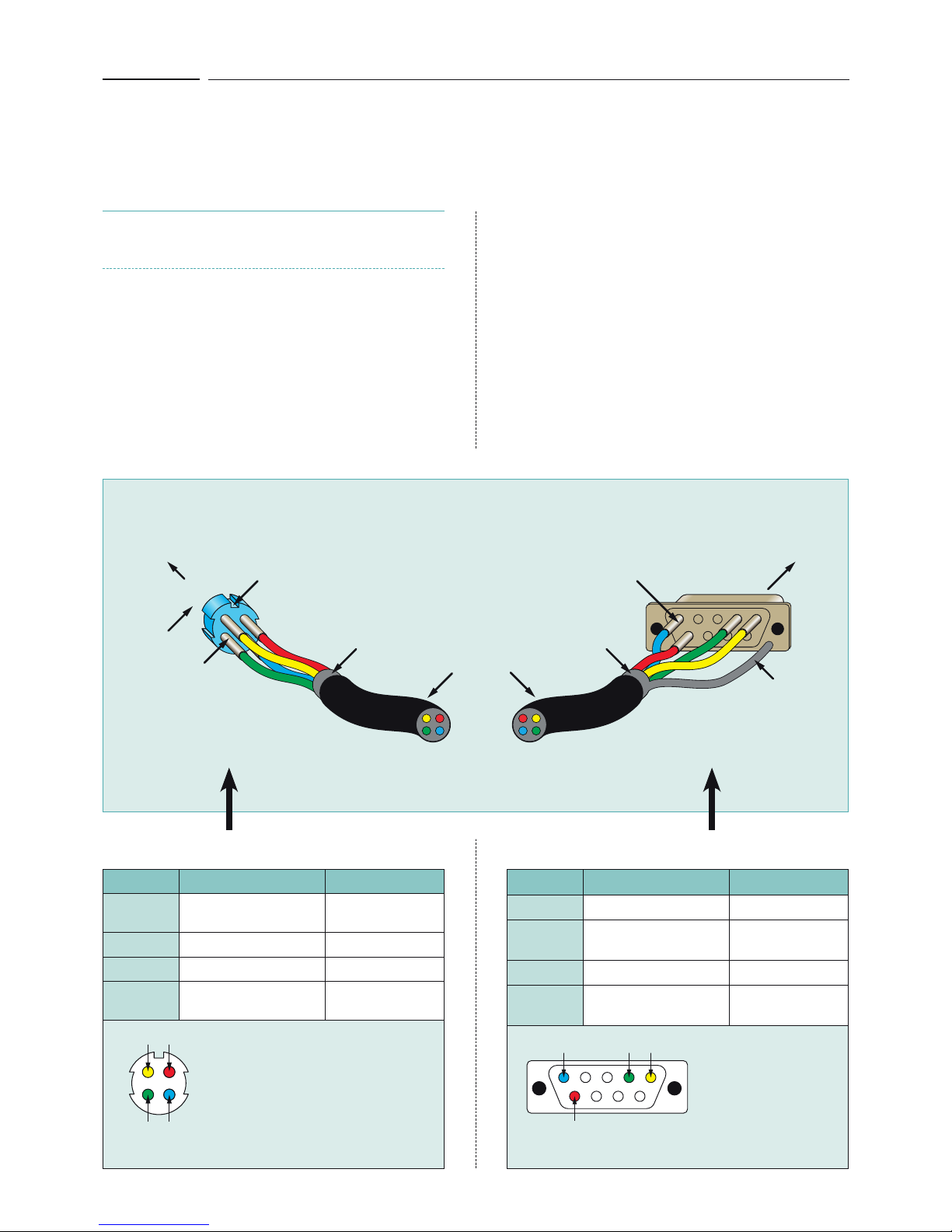
CABLE AND SOCKET
CONNECTORS WIRING GUIDE
The M425 Transducer is supplied with a standard 3 metre
signal cable. This cable is terminated with a standard
9-way D connector to interface to any of the Datum
Electronics Signal Interfaces or Indicators.
The connections within this cable are detailed below should
you wish to connect the M425 Transducer directly into your
own instrumentation and software.
The default signal output from the Transducer is RS485 Serial
Data (see protocol section for data output details on page 11).
We have also provided the Triad 4-way plug wiring
arrangement in diagram No. 10 below for the Transducer end
of the cable. On some occasions a cable may need to be
assembled after laying through tight bulkhead access which
may require the removal of the connectors.
The maximum cable length for the M425 Transducer is
normally 200 metres. For special applications with the right
cable conditions this can increase to 500 metres depending
on the sample rate and baud rate.
The data cable from the M425 Transducer to an interface
must meet the following specification: 4 core wire, braided,
screened, 7/02mm PVC Sheathed cable or equivalent.
The M425 Transducer current consumption is less than
250mA with a 12Vdc supply. The M425 Transducer complete
with its Universal Signal Interface will consume below 450mA.
Note: alignment
notch at top of
contact carrier
Max Cable length = 200m
Pins out
Pins solder side
Shielding
Multi-core
cable
To M425 Torque
Transducer
Pins solder side
Solder
shielding
to tab
Shielding
To Universal
Interface
Male plug connector
Triad T01-550-P04
Female 9 PIN
D Connector RS485
Triad 4-way Plug T01-550-P04 wiring guide 9-way D connector RS485 wiring guide
Diagram No. 9
Pin Out Function Cable Colour
Pin 1
+12Vdc supply
to Transducer
RED
Pin 2
Supply ground BLUE
Pin 3
RS485 A: -ve data YELLOW
Pin 4
RS485 B: +ve data
RS232 TX/RX (option)
GREEN
PIN numbering viewed
from solder/cable side
of the connector
Pin Out Function Cable Colour
Pin 1
RS485 A: -ve data YELLOW
Pin 2
RS485 B: +ve data
RS232 TX/RX (option)
GREEN
Pin 5
Supply ground BLUE
Pin 9
+12Vdc supply
to Transducer
RED
PIN numbering viewed
from solder/cable side
of the connector
Diagram No. 10 Diagram No. 11
5
291
5
31
42
291
Transducer signal cable wiring guide
 Loading...