

Datsun 411 Series, P411-U, PL411-U, P411-UT, PL411-UT Service Manual
...
SERVICE
MANUAL
hotor co*, ltd
TOKYO,JAPAN
P/N 99999- 20002
SERVICE
MANUAL
expert22 fl/ia http://rutracker.org
1
NISSAN
NISSAN HOTOft CO., LTD Hi • W0
TOKYO,JAPAN
P/N 99999-
20002
DATSUN
MODEL 411 SERIES
SERVICE
MANUAL
Hoeoe umx 3ah torrents.ru IMS'
NISSAN
NISSAN MOTOR CO., LTD.
OTEMACHI BLOG., OTEMACHI, CHIYODA-KU,
TOKYO,JAPAN
CABLE ADDRESS : "NISMO" TOKYO
PHONES : (216) 2311
expert22 http://rutracker.org
INT RODUC TION
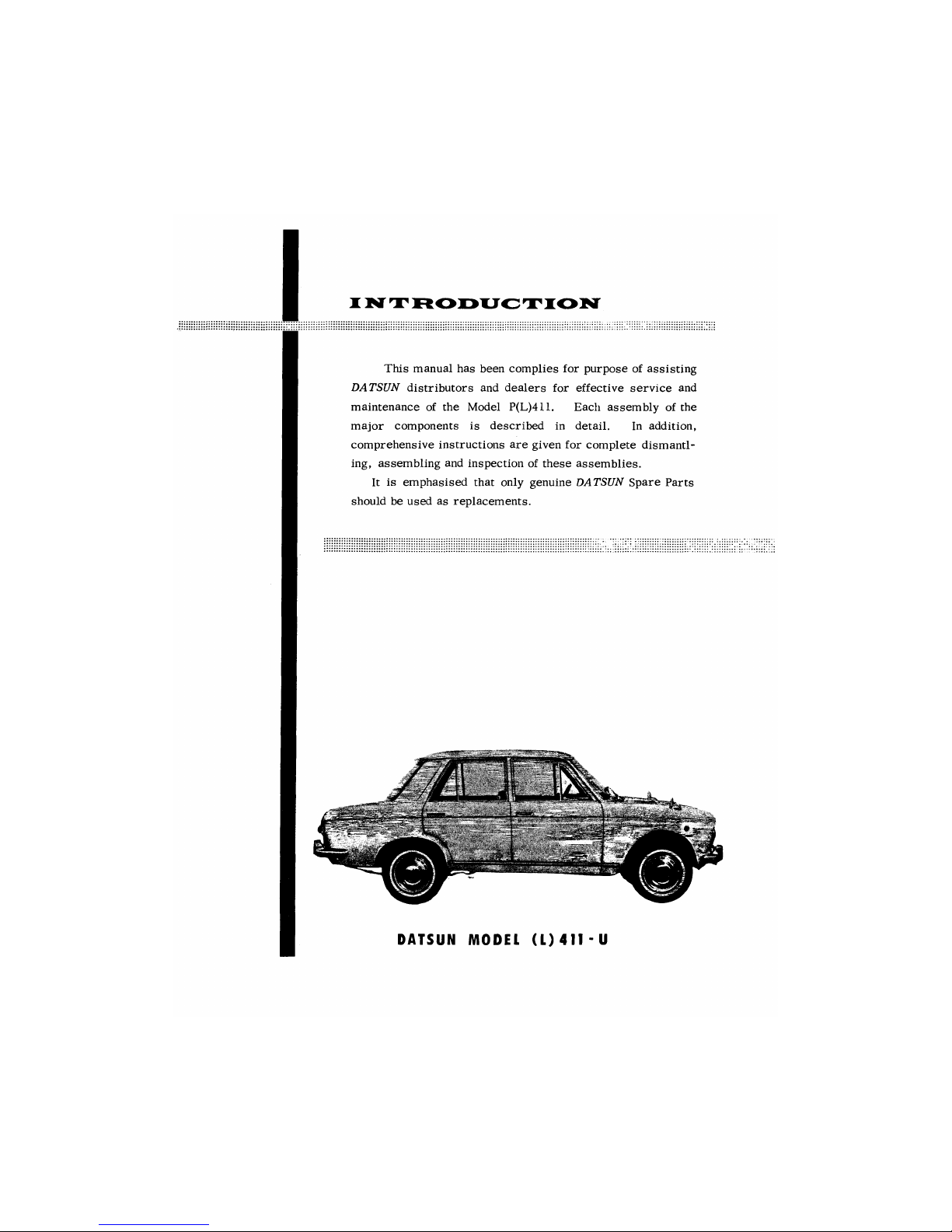
This manual has been complies for purpose of assisting
DATSUN distributors and dealers for effective service and
maintenance of the Model P(L)411. Each assembly of the
major components
is
described in detail. In addition,
comprehensive instructions are given for complete dismantl-
ing, assembling and inspection of these assemblies.
It is emphasised that only genuine DATSUN Spare Parts
should be used as replacements.
DATSUN MODEL (L) 411 - U
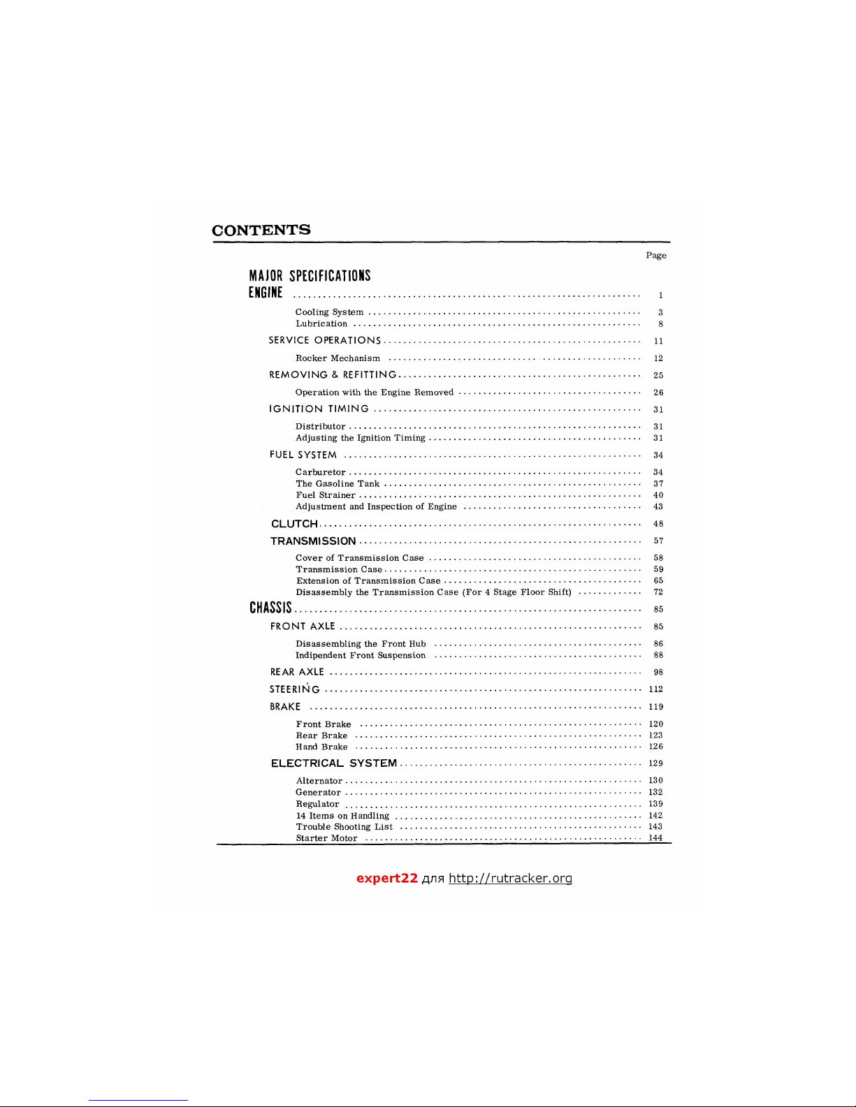
CONTENTS
Page
MAJOR SPECIFICATIONS
ENGINE
i
Cooling System 3
Lubrication 8
SERVICE OPERATIONS 11
Rocker Mechanism 12
REMOVING & REFITTING 25
Operation with the Engine Removed 26
IGNITION TIMING 31
Distributor 31
Adjusting the Ignition Timing 31
FUEL SYSTEM 34
Carburetor 34
The Gasoline Tank 37
Fuel Strainer 40
Adjustment and Inspection of Engine 43
CLUTCH 48
TRANSMISSION 57
Cover of Transmission Case 58
Transmission Case 59
Extension of Transmission Case 65
Disassembly the Transmission Case (For 4 Stage Floor Shift) 72
CHASSIS
ss
FRONT AXLE 85
Disassembling the Front Hub 86
Indipendent Front Suspension 88
REAR AXLE 98
STEERING 112
BRAKE 119
Front Brake 120
Rear Brake 123
Hand Brake 126
ELECTRICAL SYSTEM 129
Alternator 130
Generator 132
Regulator 139
14 Items on Handling 142
Trouble Shooting List 143
Starter Motor 144
expert22 ajia http://rutracker.orq
DISMOUNTING & ASSEMBLING
MAJOR SPECIFICATION
OF
MODEL
41 1
SERIES
"— ____^MODEL
ITEM
~~
P(
L) 41
1-U
P(
L) 4 1
1-UT
WP(
L) 41
1-U
WP(L)41
1-UT
DIMENSIONS
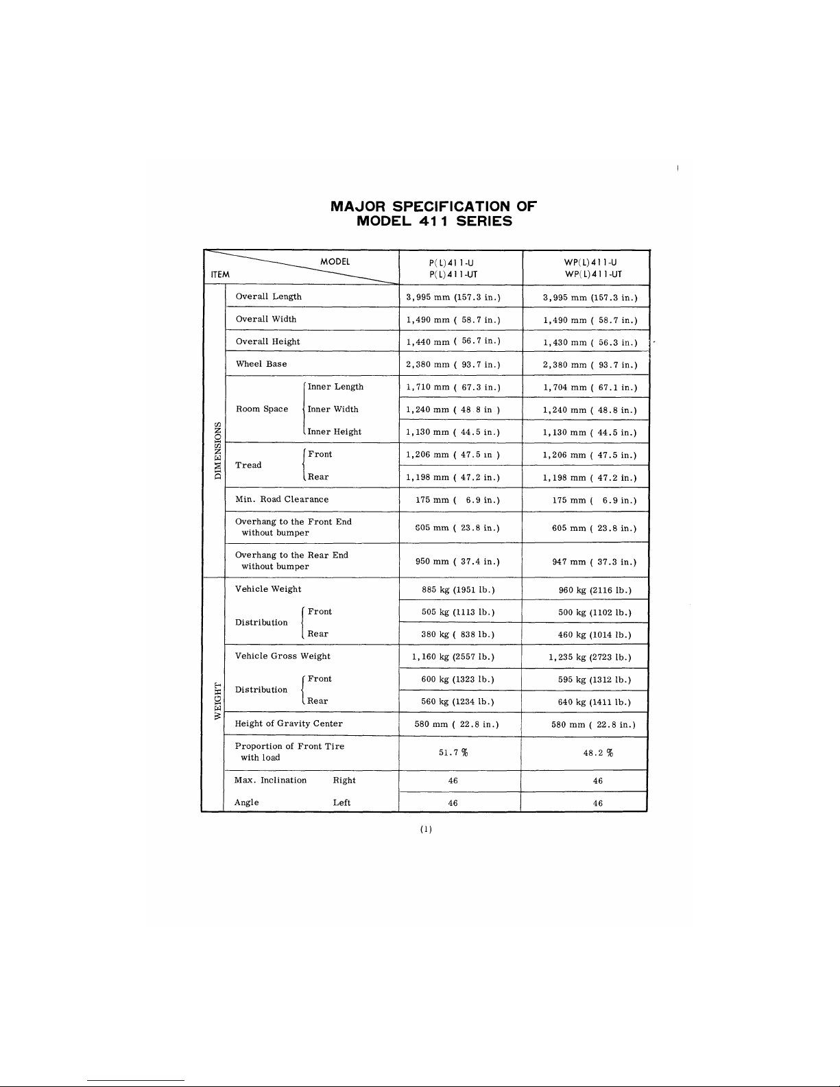
Overall Length
3,995
mm
(157.3
in.)
3,995
mm
(157.3
in.)
DIMENSIONS
Overall Width
1,490
mm ( 58.7 in.)
1,490
mm ( 58.7 in.)
DIMENSIONS
Overall Height
1,440
mm ( 56.7 in.)
1,430
mm ( 56.3 in.)
DIMENSIONS
Wheel Base
2,380
mm (93.7 in.)
2,380
mm ( 93.7 in.)
DIMENSIONS
Room Space
Inner Length
Inner Width
.
Inner Height
1,710
mm ( 67.3 in.)
1,704
mm ( 67.1 in.)
DIMENSIONS
Room Space
Inner Length
Inner Width
.
Inner Height
1,240
mm (
48
.8 in-)
1,240
mm ( 48.8 in.)
DIMENSIONS
Room Space
Inner Length
Inner Width
.
Inner Height 1,130
mm ( 44.5 in.)
1,130
mm ( 44.5 in.)
DIMENSIONS
Tread
Front
,Rear
1,206
mm ( 47.5 in )
1,206
mm ( 47.5 in.)
DIMENSIONS
Tread
Front
,Rear 1,198
mm ( 47.2 in.)
1,198
mm ( 47.2 in.)
DIMENSIONS
Min. Road Clearance
175
mm ( 6.9 in.)
175
mm ( 6.9 in.)
DIMENSIONS
Overhang
to the
Front
End
without bumper
S05
mm ( 23.8 in.)
605
mm ( 23.8 in.)
DIMENSIONS
Overhang
to the
Rear
End
without bumper
950
mm ( 37.4 in.)
947
mm ( 37.3 in.)
WEIGHT
Vehicle Weight
885
kg
(1951
lb.)
960
kg
(2116
lb.)
WEIGHT
Distribution
Front
Rear
505
kg
(1113
lb.)
500
kg
(1102
lb.)
WEIGHT
Distribution
Front
Rear
380
kg ( 838 lb.)
460
kg
(1014
lb.)
WEIGHT
Vehicle Gross Weight
f Front
Distribution
I
(.Rear
1,160
kg
(2557
lb.)
1,235
kg
(2723
lb.)
WEIGHT
Vehicle Gross Weight
f Front
Distribution
I
(.Rear
600
kg
(1323
lb.)
595
kg
(1312
lb.)
WEIGHT
Vehicle Gross Weight
f Front
Distribution
I
(.Rear
560
kg (1234 lb.)
640
kg
(1411
lb.)
WEIGHT
Height
of
Gravity Center
580
mm ( 22.8 in.)
580
mm ( 22.8 in.)
WEIGHT
Proportion
of
Front Tire
with load
51.7
%
48.2
%
WEIGHT
Max. Inclination Right
Angle Left
46
46
WEIGHT
Max. Inclination Right
Angle Left
46
46
(i)
DATSUN
^ MODEL
ITEM —
P(
L) 41
1-U
P(
L) 41
1-UT
WP(
L) 41
1-U
WP(L)41 1-UT
w
o
£
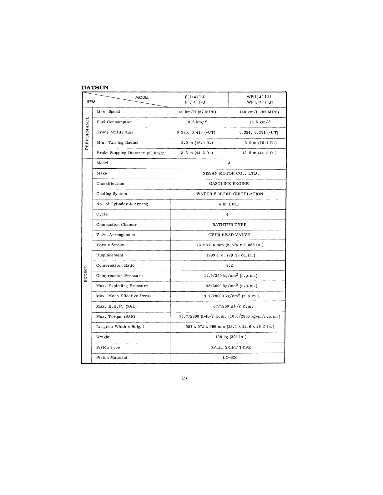
Max. Speed
140 km/H (87 MPH) 140 km/H (87 MPH)
w
o
£
Fuel Consumption
18.5 km/£
18.5 km/£
§
K
O
Grade Ability sinfl
0.375, 0.417 (-UT)
0.334, 0.391 (-UT)
fe
w
w
ft
Min. Turning Radius
5
.0 m (16.4 ft.) 5.0 m (16.4 ft.)
fe
w
w
ft
Brake Stopping Distance (50 km/h'
13
5 m (44.3 ft.) 13.5 m (44.3 ft.)
Model
J
Make
NISSAN MOTOR CO., LTD.
Classification
GASOLINE ENGINE
Cooling System
WATER FORCED CIRCULATION
No. of Cylinder & Arrang.
4 IN LINE
Cycle
4
Combustion Chamer
BATHTUB TYPE
Valve Arrangement
OVER HEAD VALVE
Bore x Stroke
73 x 77.6 mm (2 .874 x 3.055 in.)
Displacement
1299 c.c. (79.27 cu.in.)
w
y
Compression Ratio 8.2
a
o
fc
w
Compression Pressure 11.5/350 kg/cm2 (r.p.m.)
a
o
fc
w
Max. Exploding Pressure
48/3600 kg/cm2 (r.p.m.)
Max. Mean Effective Press
9.7/28000 kg/cm2 (r.p.m.)
Max. B.H.P. (SAE) 67/5200 HP/r.p.m.
Max. Torque (SAE)
76 .7/2800 ft-lb/r.p.m. (10.6/2800 kg-m/r.p.m.)
Length x Width x Height
597 x 575 x 690 mm (23.1 x 22.6 x 26.5 in.)
Weight
139 kg (306 lb.)
Piston Type SPLIT SKIRT TYPE
Piston Material LO
-EX
(2)
MAJOR SPECIFICATION
ITEM
MODEL
P (
L) 41
1-U
P(
L) 4 1 1
-UT
WP(
L) 4 1
1-U
WP(L)41 1-UT
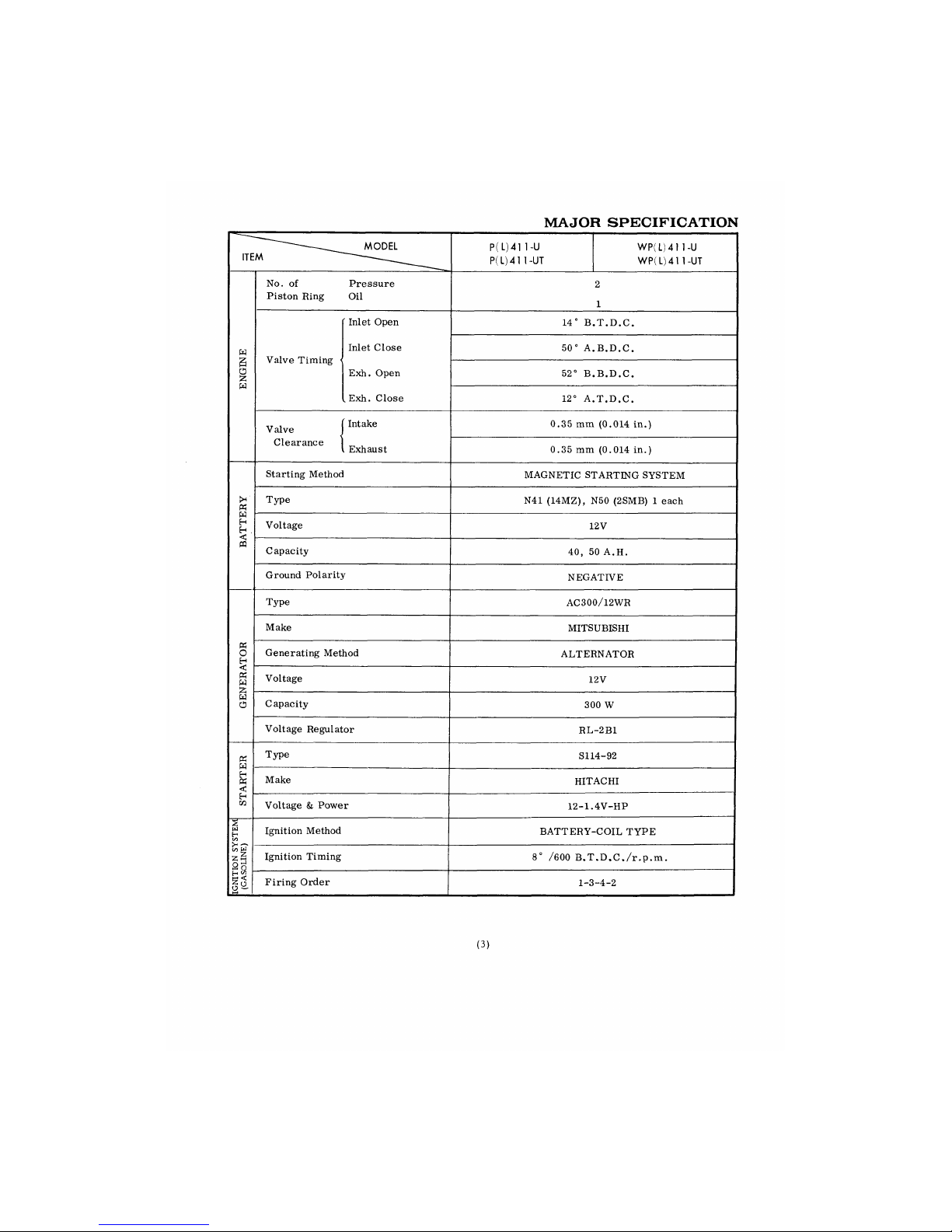
No. of
Piston Ring
Pressure
Oil
2
1
' Inlet Open
14° B
.T.D.C.
w
Valve Timing •
Inlet Close
50° A
B.D.C.
U
O
£
w
Valve Timing •
Exh. Open
52° B
.B.D.C.
U
O
£
w
. Exh. Close
12° A
T.D.C.
Valve
Intake
0.35 mm (0.014 in.)
Clearance
, Exhaust
0.35 mm (0.014 in.)
Starting Method
MAGNETIC STARTING SYSTEM
K
Type
N41 (14MZ), N50 (2SMB) 1 each
w
H
H ,
<
Voltage
12V
CQ
Capacity
40, 50 A.H.
Ground Polarity
NEGATIVE
Type
AC300/12WR
Make
MITSUBISHI
K
O H Generating Method
ALTERNATOR
<1
«
W
Voltage
12V
W
O
Capacity
300 W
Voltage Regulator
RL -2B1
K
W
H
«
<
Type
S114-92
K
W
H
«
<
Make
HITACHI
H
Voltage & Power
12-1.
4V-HP
S
w
H
Irt
—
K
W
Ignition Method
BATTERY-
-COIL TYPE
S
w
H
Irt
—
K
W
Ignition Timing
8° /600 B.T.D.C./r.p.m.
g <
Firing Order
1-3 -4-2
(3)
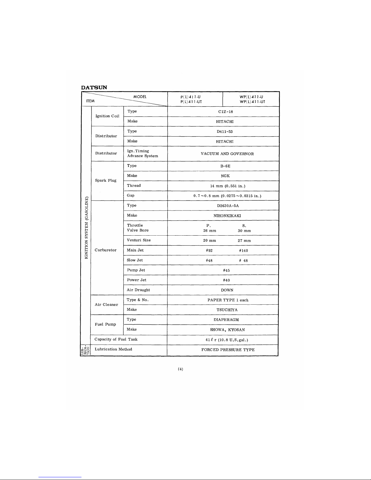
DATSUN
ITEM
MODEL
P(L)41 1-U
P(
L) 41
1-UT
WP(L)4 1 1-U
WP(L)41 1-UT
Ignition Coil
Type
C1Z-18
Ignition Coil
Make
HITACHI
Distributor
Type
D411-53
Distributor
Make
HITACHI
Distributor
Ign.Timing
Advance System
VACUUM AND GOVERNOR
Type
B
-6E
Spark Plug
Make
NGK
Spark Plug
Thread
14 mm (0.551 in.)
w
Gap
0. 7 ~0.8 mm (0.0275 ~0.0315 in.)
s
hJ
o
Type
D2630A-5A
CO
<
O
Make
NIHONKIKAKI
§
w
H
CO
>H
Throttle
Valve Bore
P.
26 mm
S.
30 mm
M
S3
o
Venturi Size
20 mm
27 mm
h-1
H
h—1
Z
Carburetor
Main Jet
#92 #140
O
t
Slow Jet
#48 # 48
Pump Jet
#45
Power Jet
#40
Air Draught
DOWN
Air Cleaner
Type & No.
PAPER TYPE 1 each
Air Cleaner
Make
TSUCHIYA
Fuel Pump
Type
DIAPHRAGM
Fuel Pump
Make
SHOWA, KYOSAN
Capacity of Fuel Tank
41^ r (10.8 U.S.gal.)
LUB-
RICA-
TION
Lubrication Method
FORCED PRESSURE TYPE
(4)
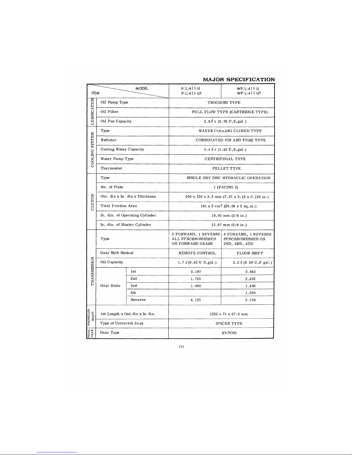
MAJOR SPECIFICATION
—MODEL
ITEM
P (
L) 41
1-U
P(
L) 41
1-UT
WP(
L) 41
1-U
WP(L)41
1-UT
LUBRICATION
Oil Pump Type
TROCHOID TYPE
LUBRICATION
Oil Filter
FULL FLOW TYPE (CARTRIDGE TYPE)
LUBRICATION
Oil
Pan
Capacity
2.9 £ r (0.76
U.S.gal.)
COOLING
SYSTEM
Type
WATER COOKING CLOSED TYPE
COOLING
SYSTEM
Radiator
CORRUGATED
FIN AND
TUBE TYPE
COOLING
SYSTEM
Cooling Water Capacity
5.4
£r
(1.43
U.S.gal.)
COOLING
SYSTEM
Water Pump Type
CENTRIFUGAL TYPE
COOLING
SYSTEM
Thermostat
PELLET TYPE
CLUTCH
Type
SINGLE
DRY
DISC HYDRAULIC OPERATION
CLUTCH
No.
of
Plate
1 (FACING
2)
CLUTCH
Out.
dia x In. dia x
Thickness
200 x 130
x 3.5 mm
(7.87 x 5.12 x 0.138
in.)
CLUTCH
Total Friction Area
181
x 2 cm2 (28.06
x 2
sq.in.)
CLUTCH
In.
dia. of
Operating Cylinder
19.05
mm
(3/4
in.)
CLUTCH
In.
dia. of
Master Cylinder
15.87
mm
(5/8
in.)
TRANSMISSION
Type
3 FORWARD, 1 REVERSE
ALL SYNCHROMESHED
ON FORWARD GEARS
4 FOREARD, 1 REVERSE
SYNCHROMESHED
ON
2ND,
3RD, 4TH
TRANSMISSION
Gear Shift Method
REMOTE CONTROL
FLOOR SHIFT
TRANSMISSION
Oil Capacity
1.7 £(0.45 US.gal.)
2.2 £ (0.58
U.S.
gal.)
TRANSMISSION
Gear Ratio
1st
3.197 3.945
TRANSMISSION
Gear Ratio
2nd
1.725 2.402
TRANSMISSION
Gear Ratio 3rd
1.000 1.490
TRANSMISSION
Gear Ratio
4th
1.000
TRANSMISSION
Gear Ratio
Reverse
4.125
5.159
PROPELLER
SHAFT
1st Length x Out.dia
x In dia.
1222 x 71 x 67.8
mm
PROPELLER
SHAFT
Type
of
Universal Joint
SPICER TYPE
FINAL
GEAR
Gear Type
HYPOID
(5)
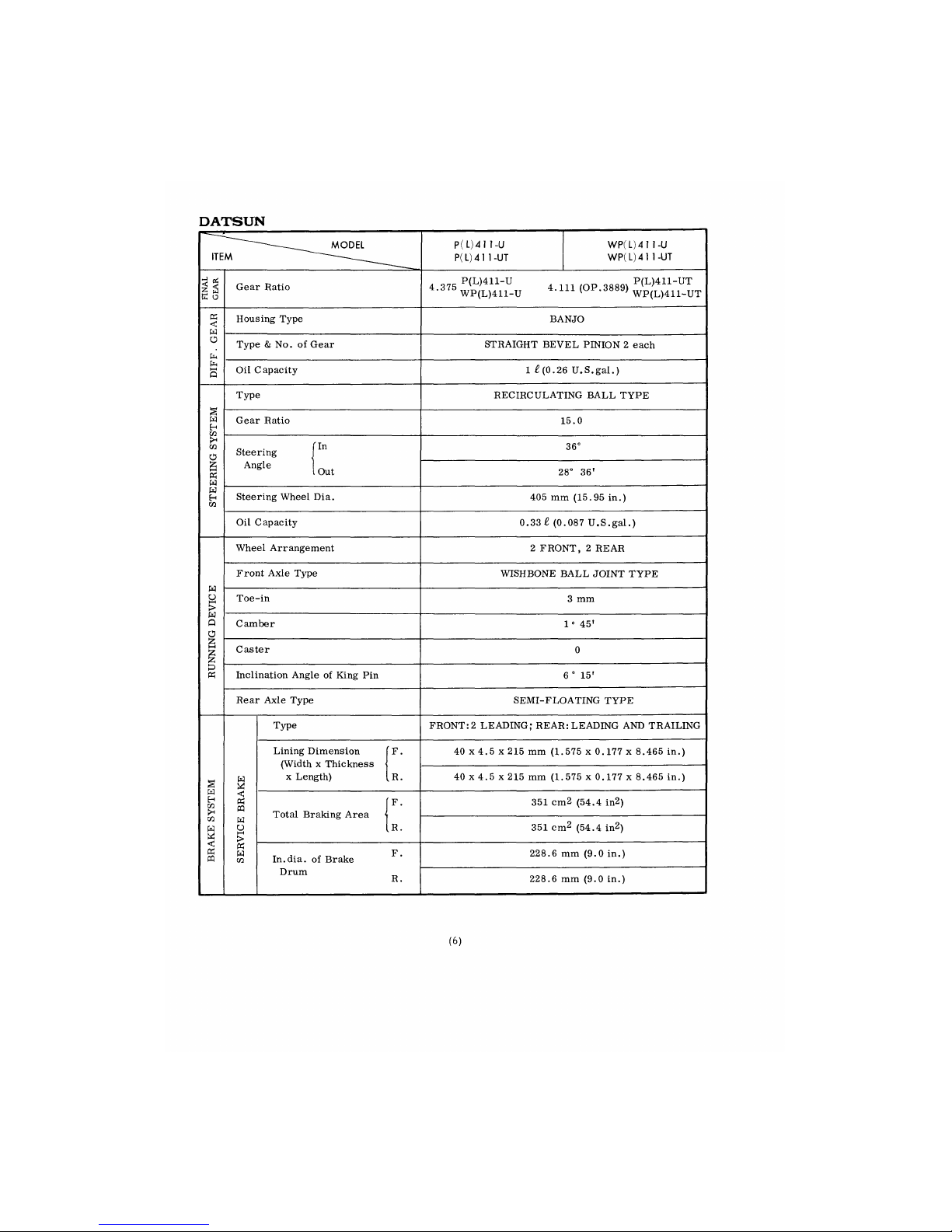
DATSUN
ITEM
——MODEL
P( L)4 1 1-U
P(
L) 4 1
1-UT
WP(L)41 1-U
WP(L)41 1-UT
£
ss
E o
Gear Ratio
4 375 P(L)
411"U
4 m
(op
3889
, P(L)411-UT
4'375
WP(L)411-U
4-111
(°P-
3889
> WP(L)411-UT
K
<
W
Housing Type
BANJO
O
Cn
Type & No. of Gear
STRAIGHT BEVEL PINION 2 each
Pn
HH
Q
Oil Capacity
1 £(0.26 U.S.gal.)
Type
RECIRCULATING BALL TYPE
2
W
H
in
Gear Ratio
15.0
CO
O
Steering J
n
36°
£
H-1
K
W
Angle
lout
28° 36'
W
H
C«
Steering Wheel Dia.
405 mm (15.95 in.)
Oil Capacity 0.33 £ (0.087 U.S.gal.)
Wheel Arrangement
2 FRONT, 2 REAR
W
o
H-1
>
W
Q
a
Front Axle Type
WISHBONE BALL JOINT TYPE
W
o
H-1
>
W
Q
a
Toe--in
3 mm
W
o
H-1
>
W
Q
a
Camber
1 0 45'
£
hH
Caster
0
«
Inclination Angle of King Pin
6 ° 15'
Rear Axle Type
SEMI-FLOATING TYPE
Type
FRONT: 2 LEADING; REAR: LEADING AND TRAILING
Lining Dimension
(Width x Thickness
x Length)
r
40 x 4.5 x 215 mm (1.575 x 0.177 x 8.465 in.)
§
w
Lining Dimension
(Width x Thickness
x Length)
u.
40 x 4.5 x 215 mm (1.
575 x 0.177 x 8.465 in.)
w
H
M
>H
<
«
PQ
Total Braking Area
r
351 cm2 (54.4 in2)
CQ
w
a
W
U
HH
>
Total Braking Area
u.
351 cm2 (54.4 in2)
<
Oh
m
K
W
M
In.dia. of Brake
F. 228.6 mm (9.0 in.)
Drum
R.
228.6 mm (9.0 in.)
(6)
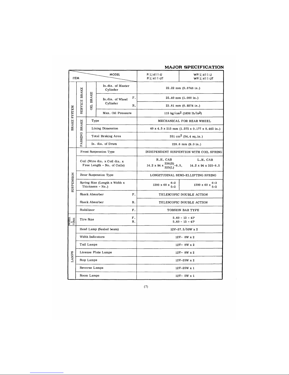
MAJOR SPECIFICATION
-——-—_MODEL
ITEM
P(
L) 4 1
1-U
P(L)41
1-UT
WP(
L) 4 1
1-U
WP(L)4 1 1-UT
BRAKE SYSTEM
SERVICE BRAKE
OIL BRAKE
In.dia.
of
Master
Cylinder
22.22
mm
(0.8748
in.)
BRAKE SYSTEM
SERVICE BRAKE
OIL BRAKE
In.dia.
of
Wheel F'
Cylinder
R.
25.40
mm
(1.000
in.)
BRAKE SYSTEM
SERVICE BRAKE
OIL BRAKE
In.dia.
of
Wheel F'
Cylinder
R.
23.81
mm
(0.9374
in.)
BRAKE SYSTEM
SERVICE BRAKE
OIL BRAKE
Max.
Oil
Pressure
115 kg/cm2 (1636
lb/in2)
BRAKE SYSTEM
PARKING
BRAKE
Type
MECHANICAL
FOR
REAR WHEEL
BRAKE SYSTEM
PARKING
BRAKE
Lining Dimension
40
x 4.5 x 215 mm
(1.575
x 0.177 x
8.465
in.)
BRAKE SYSTEM
PARKING
BRAKE
Total Braking Area
351
cm2 (54.4
sq.in.)
BRAKE SYSTEM
PARKING
BRAKE
In.
dia. of
Drum
228.6
mm (9.0 in.)
SUSPENSION
Front Suspension Type
INDEPENDENT SUSPENTION WITH COIL SPRING
SUSPENSION
Coil (Wire
dia. x
Coil
dia. x
Free Length
- No. of
Coils)
R.H.
CAR L.H. CAR
14.2
x 94 x
ffflfl-8.5,
14.2 x 94 x
325-8.5
o^5(L)
SUSPENSION
Rear Suspension Type
LONGITUDINAL SEMI-ELLIPTENG SPRING
SUSPENSION
Spring Size (Length x Width
x
Thickness
- No.)
6—2
1200
x 60 x c"
5-2
1200
x 60 x 6~l
5-Z
SUSPENSION
Shock Absorber
F.
Shoe k Abs orbe r
R.
TELESCOPIC DOUBLE ACTION
SUSPENSION
Shock Absorber
F.
Shoe k Abs orbe r
R.
TELESCOPIC DOUBLE ACTION
SUSPENSION
Stabilizer
F.
TORSION
BAR
TYPE
i
<«
a
w
5
H
Tire Size
F
'
R.
5.60
- 13 - 4P
5.60
- 13 - 4P
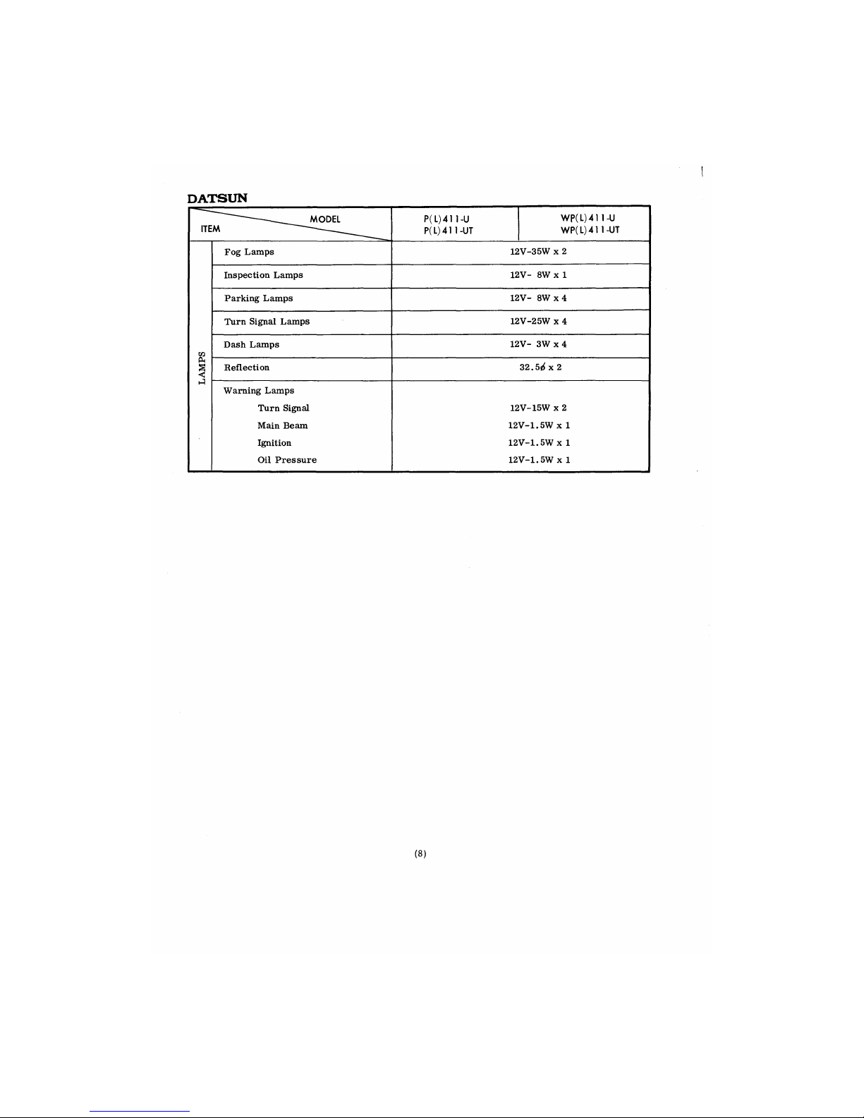
LAMPS
Head Lamp (Sealed beam)
12V-37.5/50W
x 2
LAMPS
Width Indicators
12V-
8W x 2
LAMPS
Tail Lamps
12V-
8W x 2
LAMPS
License Plate Lamps
12V-
8W x 2
LAMPS
Stop Lamps
12V-25W
x 2
LAMPS
Reverse Lamps
12V-25W
x 1
LAMPS
Room Lamps
12V-
5W x 1
(7)
DATSUN
(8)
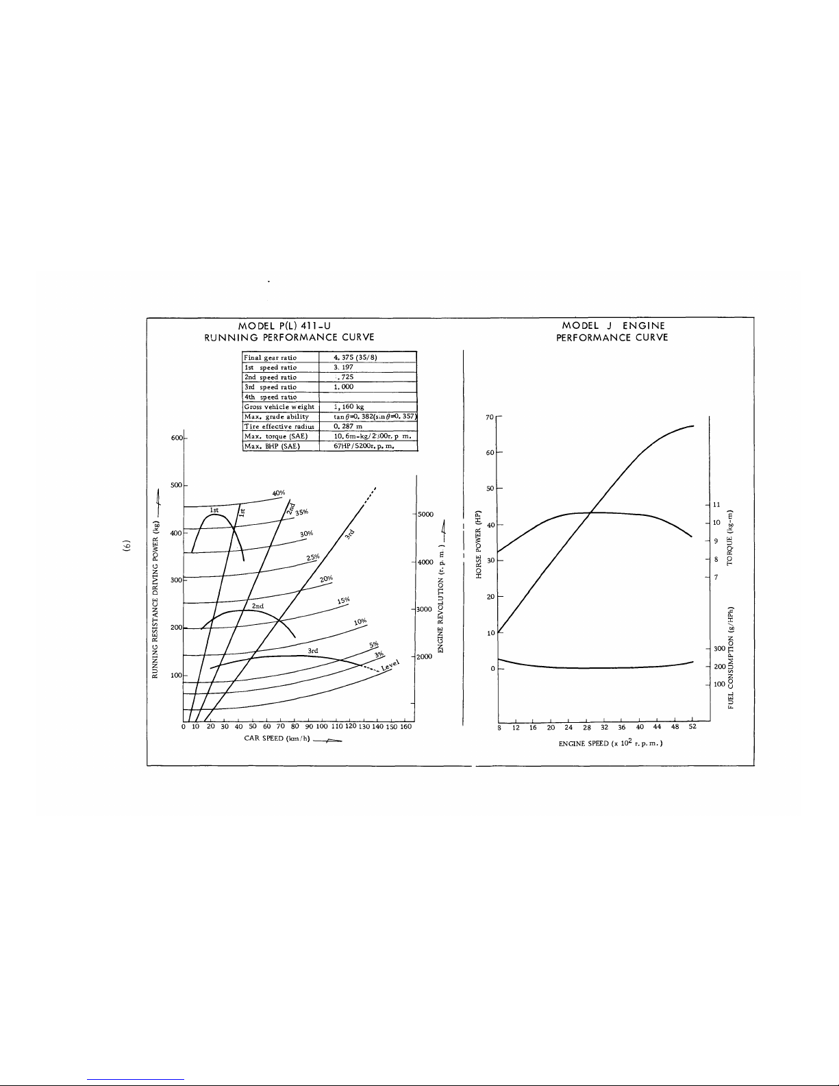
MODEL P(L) 411-U
RUNNING PERFORMANCE CURVE
Final gear ratio
4. 375 (35/8)
1st speed ratio 3. 197
2nd speed ratio
. 725
3rd speed ratio
1.000
4th speed ratio
Gross vehicle weight
1,160 kg
Max. grade ability tan 0=0. 382(sm0=O. 357)
Tire effective radius 0. 287 m
Max. torque (SAE)
10. 6m-kg/2i00r. p m.
Max. BHP (SAE)
67HP / 5200r. p. m.
0 10 20 30 40 50 60 70 80 90 100 110 120 130 140 150 160
CAR SPEED (km/h) —
MODEL J ENGINE
PERFORMANCE CURVE
ENGINE SPEED (x 102 r. p. m.)
I
CL,
M
s
'u
Q
a
a
PS
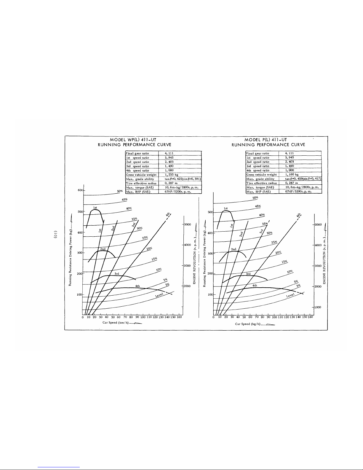
MODEL WP(L) 411-UT
RUNNING PERFORMANCE CURVE
MODEL P(L) 411-UT
RUNNING PERFORMANCE CURVE
600
500
400
300
50%
Final gear ratio
4. Ill
1st speed ratio 3.945
2nd speed ratio 2.403
3id speed ratio
1.490
4th speed ratio
1.000
Gross vehicle weight
1, 235 kg
Max. grade ability
tan 0=0. 425(sin0=O. 391)
Tire effective radius
0. 287 m
Max. torque (SAE)
10. 6m-kg/2800r. p. m.
Max. BHP (SAE)
67HP/5200r. p. m.
45^
200
100
5000
0 10 20 30 40 50 60 70 80 90 100 110 120 130 140 150 160
Car Speed (km/h) f—
3000
4000
2
O
P
D
O
>
w
pi
a
2
3
3
2000
500
i
%
o
CU
c
•c
Q
300
PS 200
3
Bfi
100
Final gear ratio
4.111 |
1st speed ratio
3.945
2nd speed ratio
2.403
3rd speed ratio
1. 490
4th speed ratio
1.000
Gross vehicle weight
1,160 kg
Max. grade ability
tan 0=0. 459(sin 0=0. 417)
Tire effective radius
0. 287 m
Max. torque (SAE)
10, 6m-kg/ 2800r. p. m.
Max. BHP (SAE)
67HP/ 5200r. p. m.
50%
45%
5000
I.
s
4000 d
2
O
P
D
O
gi
OS
w
Z
C3
2
w
3000
2000
1000
0 10 20 30 40 50 60 70 80 90 100 110 120 130 140 150 160
Car Speed (kg/h) /—._
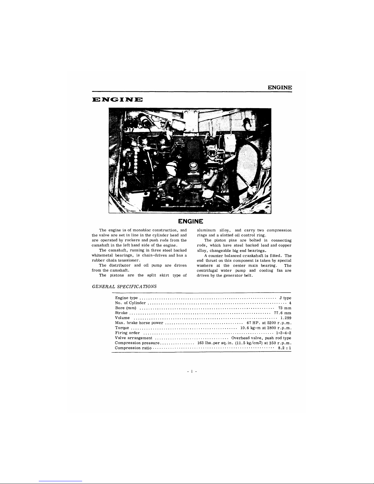
ENGINE
ENGINE
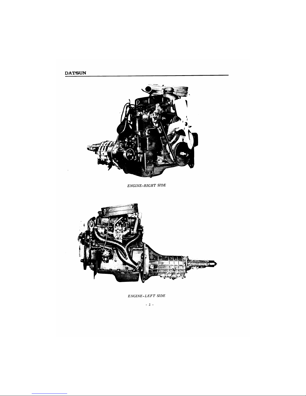
The engine is of monobloc construction, and
the valve are set in line in the cylinder head and
are operated by rockers and push rods from the
camshaft in the left hand side of the engine.
The camshaft, running in three steel backed
whitemetal bearings, is chain-driven and has a
rubber chain tenssioner.
The distributor and oil pump are driven
from the camshaft.
The pistons are the split skirt type of
aluminum alloy, and carry two compression
rings and a slotted oil control ring.
The piston pins are bolted in connecting
rods, which have steel backed lead and copper
alloy, changeable big end bearings.
A counter balanced crankshaft is fitted. The
end thrust on this component is taken by special
washers at the center main bearing. The
centrifugal water pump and cooling fan are
driven by the generator belt.
GENERAL SPECIFICATIONS
Engine type J type
No. of Cylinder 4
Bore (mm) 73 mm
Stroke 77.6 mm
Volume 1.299
Max. brake horse power 67 HP. at 5200 r.p.m.
Torque 10.6 kg-m at 2800 r.p.m.
Firing order 1-3-4-2
Valve arrangement Overhead valve, push rod type
Compression pressure 163 lbs.per sq.in. (11.5 kg/cm2) at 350 r.p.m.
Compression ratio 8.2 :1
- 1 -
DATSUN
ENGINE-RIGHT SIDE
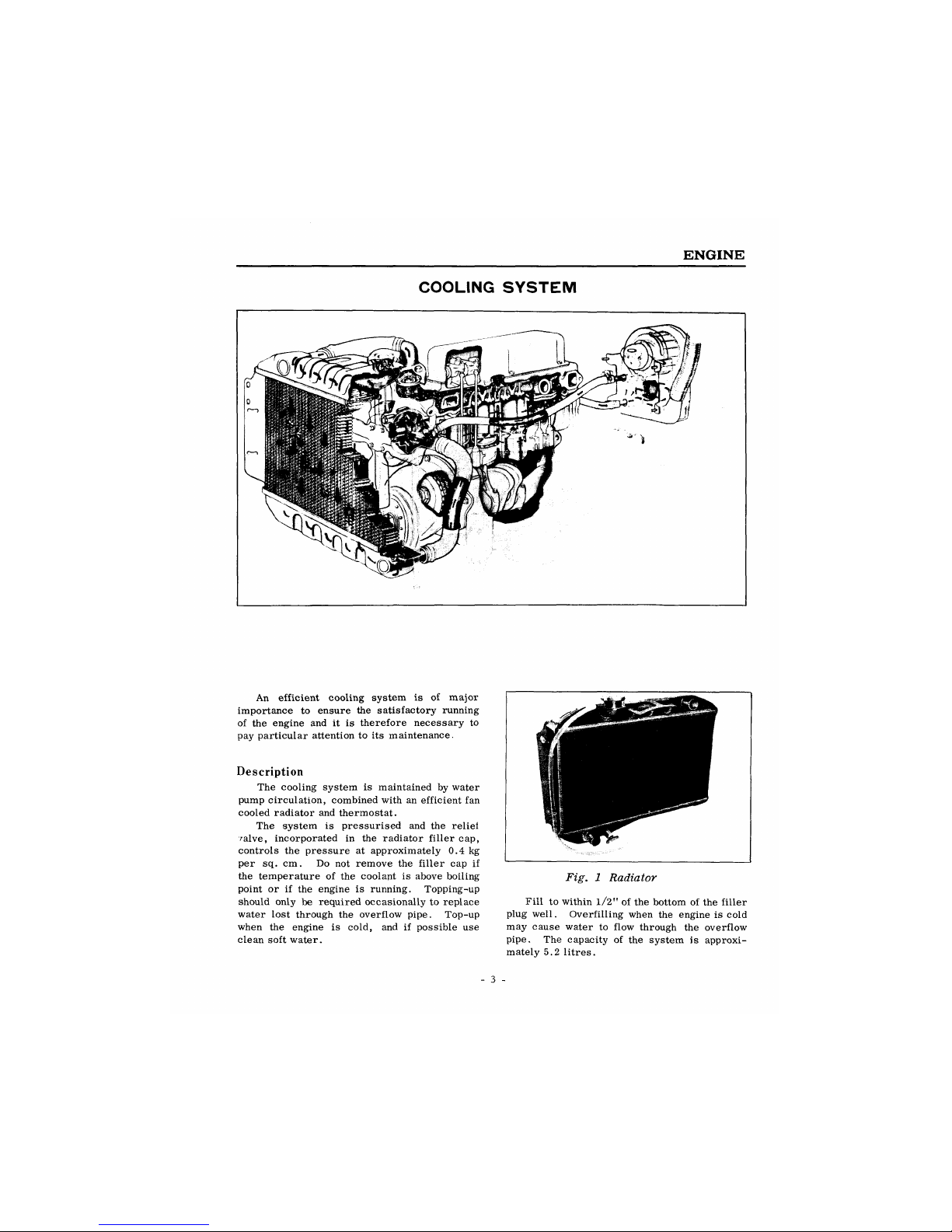
ENGINE-LEFT SIDE
- 2 -
ENGINE
COOLING SYSTEM
An efficient cooling system is of major
importance to ensure the satisfactory running
of the engine and it is therefore necessary to
pay particular attention to its maintenance.
Description
The cooling system is maintained by water
pump circulation, combined with an efficient fan
cooled radiator and thermostat.
The system is pressurised and the reliei
ralve, incorporated in the radiator filler cap,
controls the pressure at approximately 0.4 kg
per sq. cm. Do not remove the filler cap if
the temperature of the coolant is above boiling
point or if the engine is running. Topping-up
should only be required occasionally to replace
water lost through the overflow pipe. Top-up
when the engine is cold, and if possible use
clean soft water.
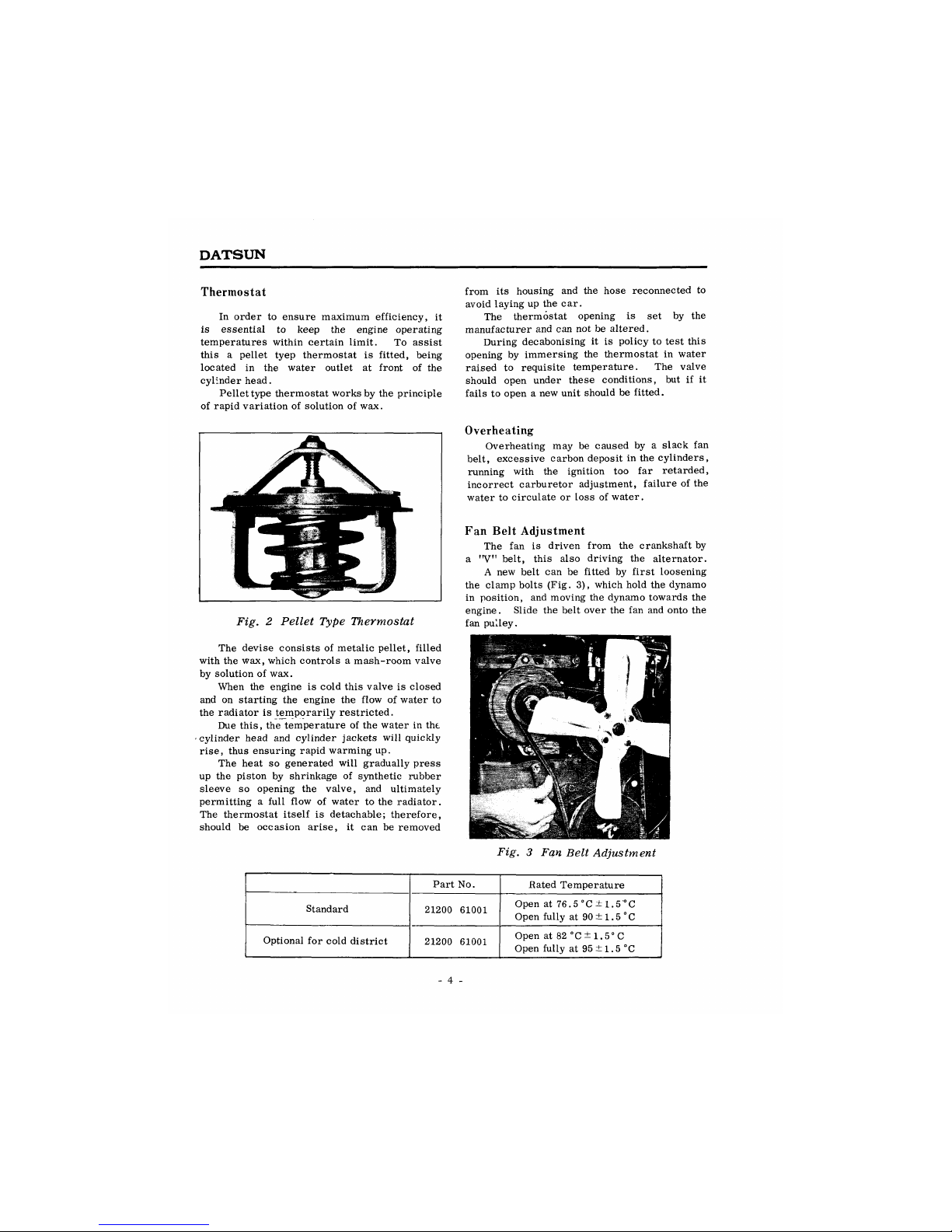
Fig. 1 Radiator
Fill to within l/2" of the bottom of the filler
plug well. Overfilling when the engine is cold
may cause water to flow through the overflow
pipe. The capacity of the system is approxi-
mately 5.2 litres.
- 3 -
DATSUN
Thermostat
In order to ensure maximum efficiency, it
is essential to keep the engine operating
temperatures within certain limit. To assist
this a pellet tyep thermostat is fitted, being
located in the water outlet at front of the
cylinder head.
Pellet type thermostat works by the principle
of rapid variation of solution of wax.
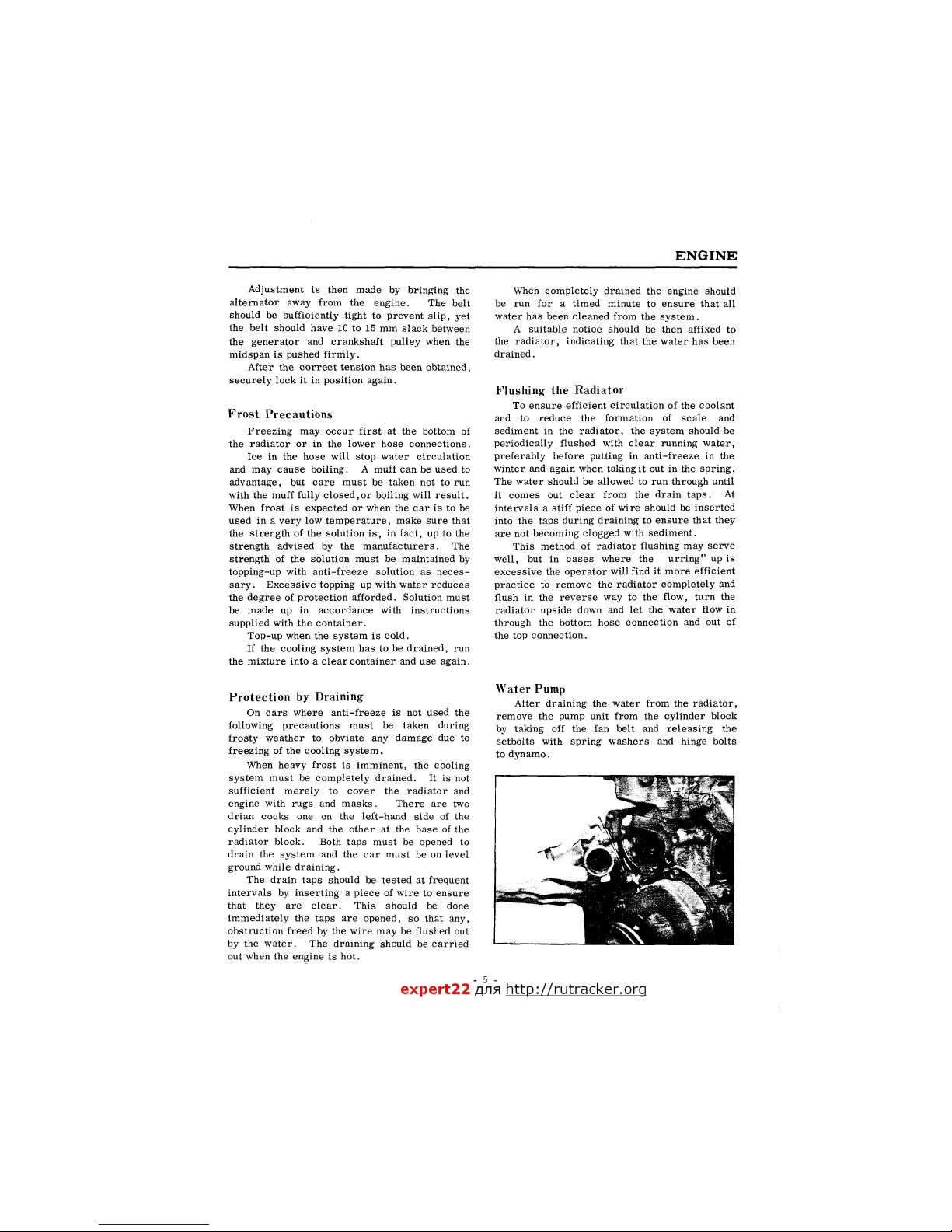
Fig. 2 Pellet Type Thermostat
The devise consists of metalic pellet, filled
with the wax, which controls a mash-room valve
by solution of wax.
When the engine is cold this valve is closed
and on starting the engine the flow of water to
the radiator is temporarily restricted.
Due this, the temperature of the water in the
cylinder head and cylinder jackets will quickly
rise, thus ensuring rapid warming up.
The heat so generated will gradually press
up the piston by shrinkage of synthetic rubber
sleeve so opening the valve, and ultimately
permitting a full flow of water to the radiator.
The thermostat itself is detachable; therefore,
should be occasion arise, it can be removed
from its housing and the hose reconnected to
avoid laying up the car.
The thermostat opening is set by the
manufacturer and can not be altered.
During decabonising it is policy to test this
opening by immersing the thermostat in water
raised to requisite temperature. The valve
should open under these conditions, but if it
fails to open a new unit should be fitted.
Overheating
Overheating may be caused by a slack fan
belt, excessive carbon deposit in the cylinders,
running with the ignition too far retarded,
incorrect carburetor adjustment, failure of the
water to circulate or loss of water.
Fan Belt Adjustment
The fan is driven from the crankshaft by
a
,r
V" belt, this also driving the alternator.
A new belt can be fitted by first loosening
the clamp bolts (Fig. 3), which hold the dynamo
in position, and moving the dynamo towards the
engine. Slide the belt over the fan and onto the
fan pulley.
Fig. 3 Fan Belt Adjustment
Part No.
Bated Temperature
Standard
21200 61001
Open at 76.5 °C ± 1.5'°C
Open fully at 90 ±1.5 °C
Optional for cold district
21200 61001
Open at 82 °C±1.5°C
Open fully at 95 ±1.5 °C
- 4 -
ENGINE
Adjustment is then made by bringing the
alternator away from the engine. The belt
should be sufficiently tight to prevent slip, yet
the belt should have 10 to 15 mm slack between
the generator and crankshaft pulley when the
midspan is pushed firmly.
After the correct tension has been obtained,
securely lock it in position again.
Frost Precautions
Freezing may occur first at the bottom of
the radiator or in the lower hose connections.
Ice in the hose will stop water circulation
and may cause boiling. A muff can be used to
advantage, but care must be taken not to run
with the muff fully closed,or boiling will result.
When frost is expected or when the car is to be
used in a very low temperature, make sure that
the strength of the solution is, in fact, up to the
strength advised by the manufacturers. The
strength of the solution must be maintained by
topping-up with anti-freeze solution as neces-
sary. Excessive topping-up with water reduces
the degree of protection afforded. Solution must
be made up in accordance with instructions
supplied with the container.
Top-up when the system is cold.
If the cooling system has to be drained, run
the mixture into a clear container and use again.
Protection by Draining
On cars where anti-freeze is not used the
following precautions must be taken during
frosty weather to obviate any damage due to
freezing of the cooling system.
When heavy frost is imminent, the cooling
system must be completely drained. It is not
sufficient merely to cover the radiator and
engine with rugs and masks. There are two
drian cocks one on the left-hand side of the
cylinder block and the other at the base of the
radiator block. Both taps must be opened to
drain the system and the car must be on level
ground while draining.
The drain taps should be tested at frequent
intervals by inserting a piece of wire to ensure
that they are clear. This should be done
immediately the taps are opened, so that any,
obstruction freed by the wire may be flushed out
by the water. The draining should be carried
out when the engine is hot.
When completely drained the engine should
be run for a timed minute to ensure that all
water has been cleaned from the system.
A suitable notice should be then affixed to
the radiator, indicating that the water has been
drained.
Flushing the Radiator
To ensure efficient circulation of the coolant
and to reduce the formation of scale and
sediment in the radiator, the system should be
periodically flushed with clear running water,
preferably before putting in anti-freeze in the
winter and again when taking it out in the spring.
The water should be allowed to run through until
it comes out clear from the drain taps. At
intervals a stiff piece of wire should be inserted
into the taps during draining to ensure that they
are not becoming clogged with sediment.
This method of radiator flushing may serve
well, but in cases where the urring" up is
excessive the operator will find it more efficient
practice to remove the radiator completely and
flush in the reverse way to the flow, turn the
radiator upside down and let the water flow in
through the bottom hose connection and out of
the top connection.
Water Pump
After draining the water from the radiator,
remove the pump unit from the cylinder block
by taking off the fan belt and releasing the
setbolts with spring washers and hinge bolts
to dynamo.
- 5 -
expert22 fl/ia http://rutracker.orq
DATSUN
Seat (set)
Washer
Pulley 21051-10600 (131 m/m dia. )
21051-10800 (143 m/m dia. )
Bearing
Fan
|
Wire lock
Hub for fan & pump pullev
Fan belt
(21067-10600)
21067-10800
(Used for 2MB type battery)
Gasket
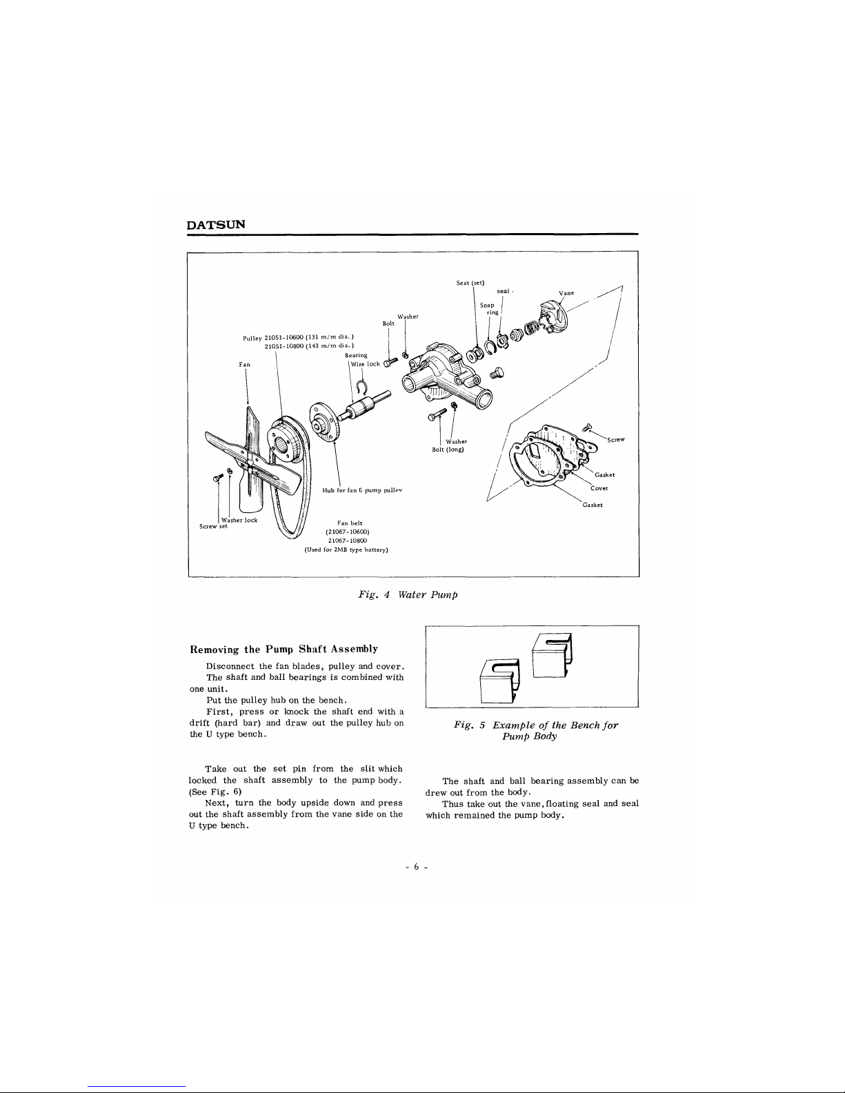
Fig. 4 Water Pump
Fig. 5 Example of the Bench for
Pump Body
Removing the Pump Shaft Assembly
Disconnect the fan blades, pulley and cover.
The shaft and ball bearings is combined with
one unit.
Put the pulley hub on the bench.
First, press or knock the shaft end with a
drift (hard bar) and draw out the pulley hub on
the U type bench.
Take out the set pin from the slit which
locked the shaft assembly to the pump body.
(See Fig. 6)
Next, turn the body upside down and press
out the shaft assembly from the vane side on the
U type bench.
The shaft and ball bearing assembly can be
drew out from the body.
Thus take out the vane,floating seal and seal
which remained the pump body.
- 6 -
ENGINE
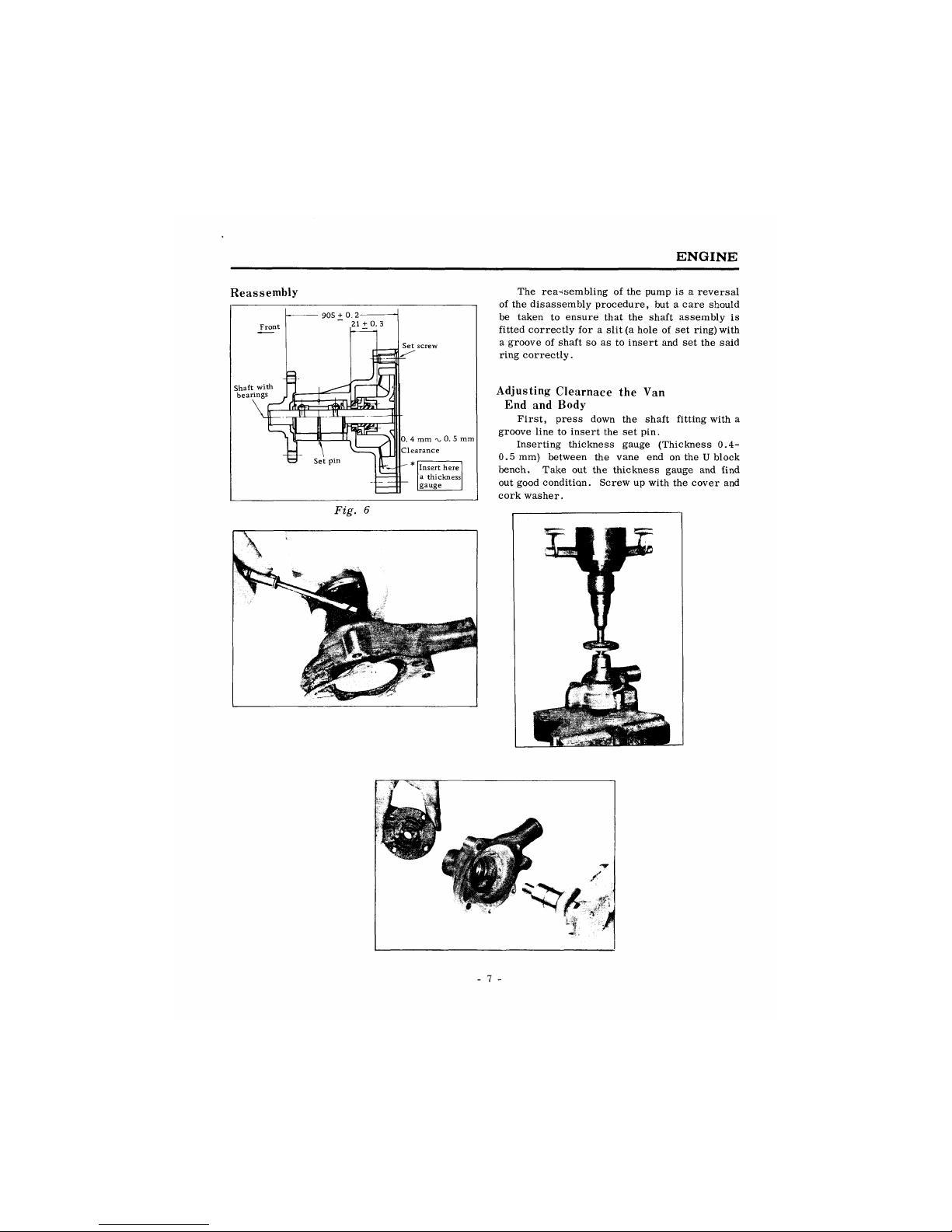
Reassembly
The reassembling of the pump is a reversal
of the disassembly procedure, but a care should
be taken to ensure that the shaft assembly is
fitted correctly for a slit (a hole of set ring) with
a groove of shaft so as to insert and set the said
ring correctly.
Adjusting Clearnace the Van
End and Body
First, press down the shaft fitting with a
groove line to insert the set pin.
Inserting thickness gauge (Thickness 0.4-
0.5 mm) between the vane end on the U block
bench. Take out the thickness gauge and find
out good condition. Screw up with the cover and
cork washer.
DATSUN
LUBRICATION
Circulation
Pressure lubrication is used throughout the
unit and is provided by an ecentric non-draining
oil pump. The oil pump is bolted into the left-
hand side of the crankcase, and is driven from
the camshaft gear by a short vertical shaft.
The oil is drawn into the pump via the filter
and is delivered through internal oilways to the
relief valve which is situated at the cover of
oil pump.
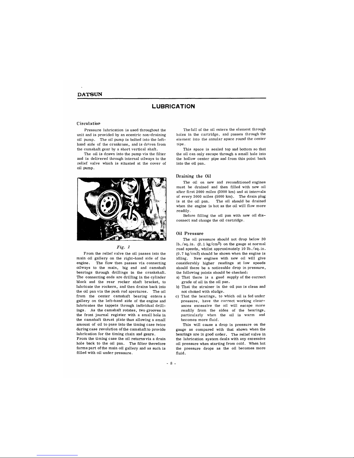
Fig. 1
From the relief valve the oil passes into the
main oil gallery on the right-hand side of the
engine. The flow then passes via connecting
oilways to the main, big end and camshaft
bearings through drillings in the crankshaft.
The connecting ends are drilling in the cylinder
block and the rear rocker shaft bracket, to
lubricate the rockers, and then drains back into
the oil pan via the push rod apertures. The oil
from the center camshaft bearing enters a
gallery on the left-hand side of the engine and
lubricates the tappets through individual drill-
ings. As the camshaft rotates, two grooves in
the front journal register with a small hole in
the camshaft thrust plate thus allowing a small
amount of oil to pass into the timing case twice
duringcase revolution ofthe camshaft to provide
lubrication for the timing chain and gears.
From the timing case the oil returns via a drain
hole back to the oil pan. The filter therefore
forms part ofthe main oil gallery and as such is
filled with oil under pressure.
The full of the oil enters the element through
holes in the cartridge, and passes through the
element into the annular space round the center
oipe.
This space is sealed top and bottom so that
the oil can only escape through a small hole into
the hollow center pipe and from this point back
into the oil pan.
Draining the Oil
The oil on new and reconditioned engines
must be drained and then filled with new oil
after first 2000 miles (3000 km) and at intervals
of every 3000 miles (5000 km). The drain plug
is at the oil pan. The oil should be drained
when the engine is hot as the oil will flow more
readily.
Before filling the oil pan with new oil dis-
connect and change the oil cartridge.
Oil Pressure
The oil pressure should not drop below 30
Ib./sq.in. (2.1 kg/cm2) on the gauge at normal
road speeds, whilst approximately 10 Ib./sq.in.
(0.7 kg/cm2) should be shown when the engine is
idling. New engines with new oil will give
considerably higher readings at low speeds
should there be a noticeable drop in pressure,
the following points should be checked:
a) That there is a good supply of the correct
grade of oil in the oil pan.
b) That the strainer in the oil pan is clean and
not choked with sludge.
c) That the bearings, to which oil is fed under
pressure, have the correct working clear-
ances excessive the oil will escape more
readily from the sides of the bearings,
particularly when the oil is warm and
becomes more fluid.
This will cause a drop in pressure on the
gauge as compared with that shown when the
bearings are in good order. The relief valve in
the lubrication system deals with any excessive
oil pressure when starting from cold. When hot
the pressure drops as the oil becomes more
fluid.
- 8 -
ENGINE
Check for Low Oil Pressure
Check the level of oil in the engine sump by
means of the dip-stick and top up if necessary.
If the warning light is still on after refilling the
sump, switch off and ascertain that the gauge
strainer in the sump is clean and not chocked
with sludge, sale that no air leakage exists at
the strainer union on the suction side of the oil
pump being defective, remove the unit and
rectify the fault.
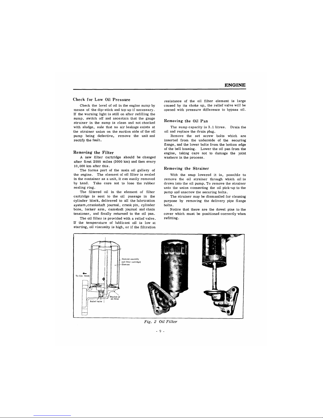
Removing the Filter
A new filter cartridge should be changed
after first 2000 miles (3000 km) and then every
10,000 km after this.
The forms part of the main oil gallery of
the engine. The element of oil filter is sealed
in the container as a unit, it can easily removed
by hand. Take care not to lose the rubber
sealing ring.
The filtered oil in the element of filter
cartridge is sent to the oil passage in the
cylinder block, delivered to all the lubrication
system,crankshaft journal, crank pin, cylinder
bore, locker arm, camshaft journal and chain
tensioner, and finally returned to the oil pan.
The oil filter is provided with a relief valve.
If the temperature of lublicant oil is low at
starting, oil viscosity is high, or if the filtration
resistance of the oil filter element is large
caused by its choke up, the relief valve will be
opened with pressure difference to bypass oil.
Removing the Oil Pan
The sump capacity is 3.1 litres. Drain the
oil and replace the drain plug.
Remove the set screw bolts which are
inserted from the underside of the securing
flange, and the lower bolts from the bottom edge
of the bell housing. Lower the oil pan from the
engine, taking care not to damage the joint
washers in the process.
Removing the Strainer
With the snup lowered it is, possible to
remove the oil strainer through which oil is
drawn into the oil pump. To remove the strainer
unto the union connecting the oil pick-up to the
pump and unscrew the securing bolts.
The strainer may be dismantled for cleaning
purpose by removing the delivery pipe flange
bolts.
Notice that there are the dowel pins to the
cover which must be positioned correctly when
refitting.
Fig. 2 Oil Filter
- 9 -
DATSUN
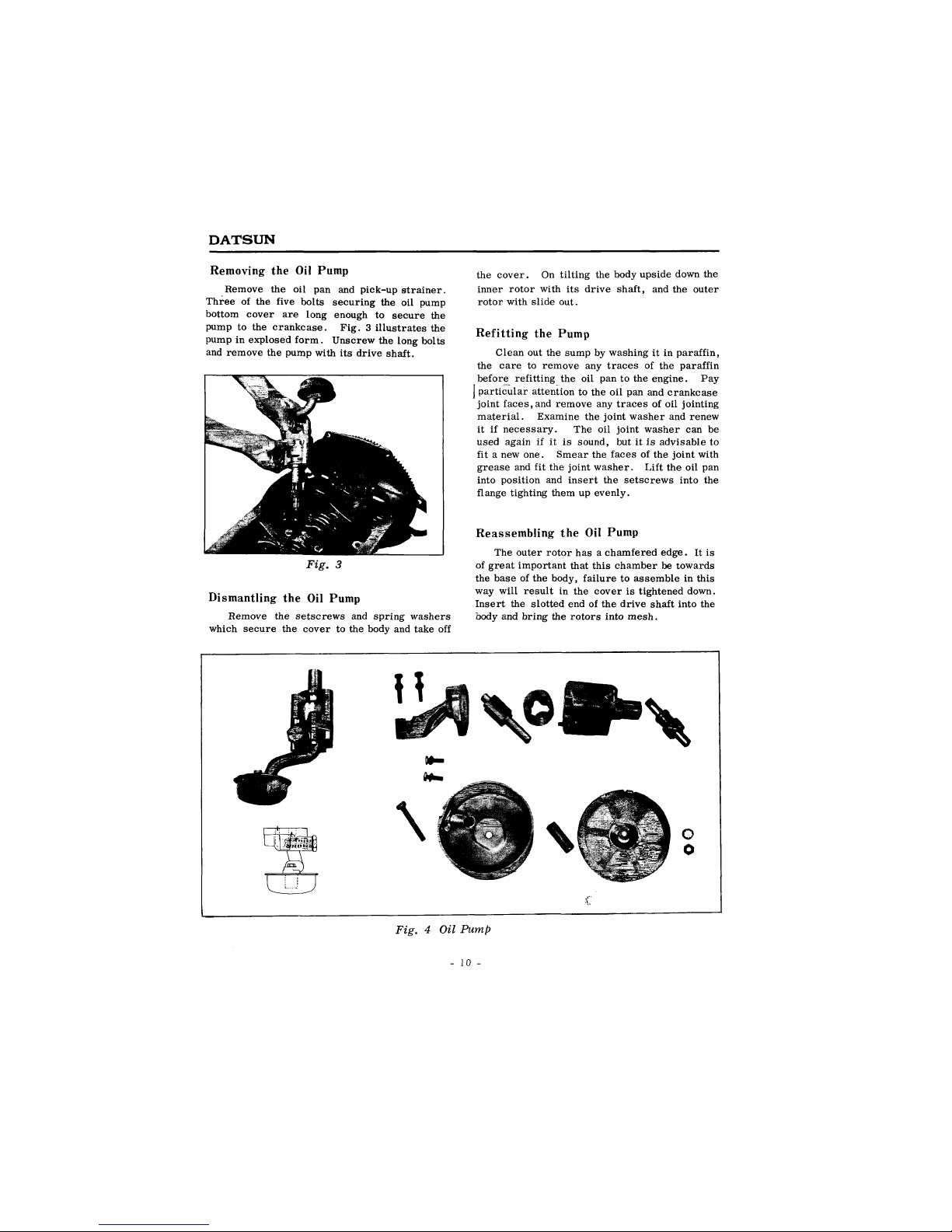
Removing the Oil Pump
Remove the oil pan and pick-up strainer.
Three of the five bolts securing the oil pump
bottom cover are long enough to secure the
pump to the crankcase. Fig. 3 illustrates the
pump in explosed form. Unscrew the long bolts
and remove the pump with its drive shaft.
Fig. 3
Dismantling the Oil Pump
Remove the setscrews and spring washers
which secure the cover to the body and take off
the cover. On tilting the body upside down the
inner rotor with its drive shaft, and the outer
rotor with slide out.
Refitting the Pump
Clean out the sump by washing it in paraffin,
the care to remove any traces of the paraffin
before refitting the oil pan to the engine. Pay
] particular attention to the oil pan and crankcase
joint faces,and remove any traces of oil jointing
material. Examine the joint washer and renew
it if necessary. The oil joint washer can be
used again if it is sound, but it is advisable to
fit a new one. Smear the faces of the joint with
grease and fit the joint washer. Lift the oil pan
into position and insert the setscrews into the
flange tighting them up evenly.
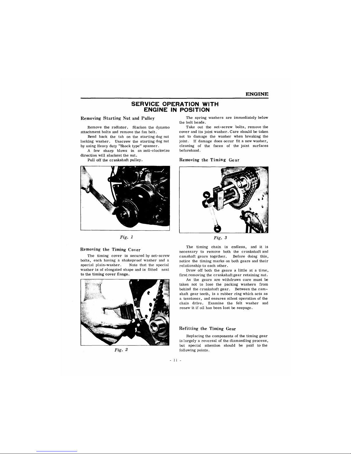
Reassembling the Oil Pump
The outer rotor has a chamfered edge. It is
of great important that this chamber be towards
the base of the body, failure to assemble in this
way will result in the cover is tightened down.
Insert the slotted end of the drive shaft into the
body and bring the rotors into mesh.
Fig. 4 Oil Pump
- 10 -
ENGINE
SERVICE OPERATION WITH
ENGINE IN POSITION
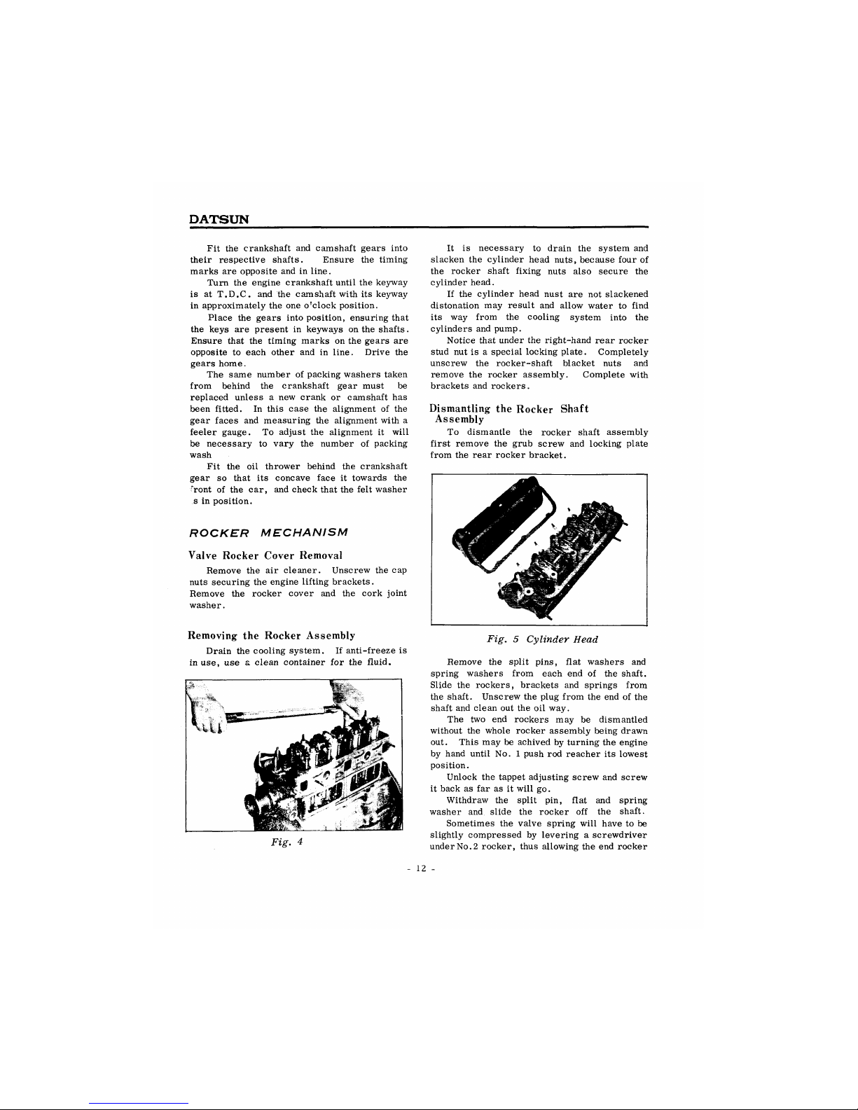
Removing Starting Nut and Pulley
Remove the radiator. Slacken the dynamo
attachment bolts and remove the fan belt.
Bend back the tab on the starting dog nut
locking washer. Unscrew the starting dog nut
by using Heavy duty "Shock type" spanner.
A few sharp blows in an anti-clockwise
direction will slackent the nut.
Pull off the crankshaft pulley.
Fig. 1
Removing the Timing Cover
The timing cover is secured by set-screw
bolts, each having a shakeproof washer and a
special plain-washer. Note that the special
washer is of elongated shape and is fitted next
to the timing cover flange.
The spring washers are immediately below
the bolt heads.
Take out the set-screw bolts, remove the
cover and its joint washer. Care should be taken
not to damage the washer when breaking the
joint. If damage does occur fit a new washer,
cleaning of the faces of the joint surfaces
beforehand.
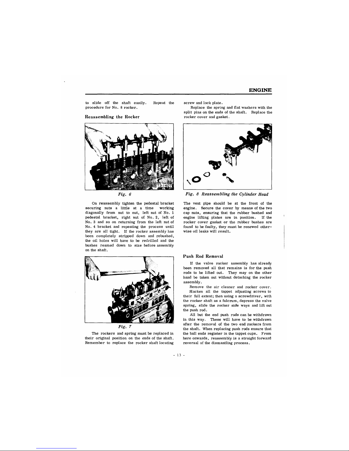
Removing the Timing Gear
Fig. 2
Fig. 3
The timing chain is endless, and it is
necessary to remove both the crankshaft and
camshaft gears together. Before doing this,
notice the timing marks on both gears and their
relationship to each other.
Draw off both the gears a little at a time,
first removing the crankshaft gear retaining nut.
As the gears are withdrawn care must be
taken not to lose the packing washers from
behind the crankshaft gear. Between the cam-
shaft gear teeth, is a rubber ring which acts as
a tensioner, and ensures silent operation of the
chain drive. Examine the felt washer and
renew it if oil has been lost be seepage.
Refitting the Timing Gear
Replacing the components of the timing gear
is largely a reversal of the dismantling process,
but special attention should be paid to the
following points.
- 11 -
DATSUN
Fit
the
crankshaft
and
camshaft gears into
their respective shafts. Ensure
the
timing
marks
are
opposite and
in
line.
Turn
the
engine crankshaft until the keyway
is
at
T.D.C.
and the
camshaft with
its
keyway
in approximately the one o'clock position.
Place
the
gears into position, ensuring that
the keys
are
present
in
keyways on the shafts.
Ensure that
the
timing marks on the gears
are
opposite
to
each other
and in
line. Drive
the
gears home.
The same number
of
packing washers taken
from behind
the
crankshaft gear must
be
replaced unless
a new
crank
or
camshaft
has
been fitted.
In
this case
the
alignment
of the
gear faces
and
measuring
the
alignment with
a
feeler gauge.
To
adjust
the
alignment
it
will
be necessary
to
vary
the
number
of
packing
wash
Fit
the oil
thrower behind
the
crankshaft
gear
so
that
its
concave face
it
towards
the
r
ront
of the car,
and check that the felt washer
s
in
position.
ROCKER MECHANISM
Valve Rocker Cover Removal
Remove
the air
cleaner. Unscrew the
cap
nuts securing the engine lifting brackets.
Remove
the
rocker cover
and the
cork joint
washer.
It
is
necessary
to
drain
the
system
and
slacken
the
cylinder head nuts, because four
of
the rocker shaft fixing nuts also secure
the
cylinder head.
If
the
cylinder head nust
are not
slackened
distonation
may
result
and
allow water
to
find
its
way
from
the
cooling system into
the
cylinders and pump.
Notice that under the right-hand rear rocker
stud nut
is a
special locking plate. Completely
unscrew
the
rocker-shaft blacket nuts
and
remove
the
rocker assembly. Complete with
brackets and rockers.
Dismantling
the
Rocker Shaft
Assembly
To dismantle
the
rocker shaft assembly
first remove
the
grub screw
and
locking plate
from the rear rocker bracket.
Removing
the
Rocker Assembly
Drain the cooling system.
If
anti-freeze
is
in use,
use a
clean container
for the
fluid.
Fig.
4
Fig. 5 Cylinder Head
Remove
the
split pins, flat washers
and
spring washers from each
end of the
shaft.
Slide
the
rockers, brackets
and
springs from
the shaft. Unscrew the plug from
the
end
of
the
shaft and clean out the
oil
way.
The
two end
rockers
may be
dismantled
without
the
whole rocker assembly being drawn
out. This may
be
achived
by
turning the engine
by hand until
No. 1
push
rod
reacher
its
lowest
position.
Unlock
the
tappet adjusting screw and screw
it back
as far as it
will
go.
Withdraw
the
split
pin,
flat
and
spring
washer
and
slide
the
rocker
off the
shaft.
Sometimes
the
valve spring will have
to be
slightly compressed
by
levering a screwdriver
under No. 2 rocker, thus allowing the end rocker
12
-
ENGINE
to slide off the shaft easily,
procedure for No. 8 rocker.
Reassembling the Rocker
Repeat the
Fig. 6
On reassembly tighten the pedestal bracket
securing nuts a little at a time working
diagonally from nut to nut, left nut of No. 1
pedestal bracket, right nut of No. 2, left of
No. 3 and so on returning from the left nut of
No. 4 bracket and repeating the process until
they are all tight. If the rocker assembly has
been completely stripped down and rebushed,
the oil holes will have to be redrilled and the
bushes reamed down to size before assembly
on the shaft.
Fig. 7
The rockers and spring must be replaced in
their original position on the ends of the shaft.
Remember to replace the rocker shaft locating
screw and lock plate.
Replace the spring and flat washers with the
split pins on the ends of the shaft. Replace the
rocker cover and gasket.
Fig. 8 Reassembling the Cylinder Head
The vent pipe should be at the front of the
engine. Secure the cover by means of the two
cap nuts, ensuring that the rubber bushed and
engine lifting plates are in position. If the
rocker cover gasket or the rubber bushes are
found to be faulty, they must be renewed other-
wise oil leaks will result.
Push Rod Removal
If the valve rocker assembly has already
been removed all that remains is for the push
rods to be lifted out. They may on the other
hand be taken out without detaching the rocker
assembly.
Remove the air cleaner and rocker cover.
Slacken all the tappet adjusting screws to
their full extent; then using a screwdriver, with
the rocker shaft as a fulcrum, depress the valve
spring, slide the rocker side ways and lift out
the push rod.
All but the end push rods can be withdrawn
in this way. These will have to be withdrawn
after the removal of the two end rockers from
the shaft. When replacing push rods ensure that
the ball ends register in the tappet cups. From
here onwards, reassembly is a straight forward
reversal of the dismantling process.
13 -
DATSUN
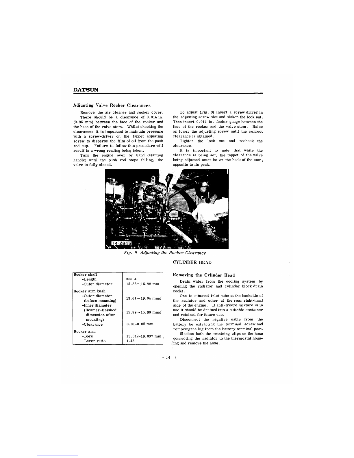
Adjusting Valve Rocker Clearances
Remove the air cleaner and rocker cover.
There should be a clearance of 0.014 in.
(0.35 mm) between the face of the rocker and
the base of the valve stem. Whilst checking the
clearances it is important to maintain pressure
with a screw-driver on the tappet adjusting
screw to disperse the film of oil from the push
rod cup. Failure to follow this procedure will
result in a wrong reading being taken.
Turn the engine over by hand (starting
handle) until the push rod stops falling, the
valve is fully closed.
To adjust (Fig. 9) insert a screw driver in
the adjusting screw slot and slaken the lock nut.
Then insert 0.014 in. feeler gauge between the
face of the rocker and the valve stem. Raise
or lower the adjusting screw until the correct
clearance is obtained.
Tighten the lock nut and recheck the
clearance.
It is important to note that while the
clearance is being set, the tappet of the valve
being adjusted must be on the back of the cam,
opposite to its peak.
Fig. 9 Adjusting the Rocker Clearance
CYLINDER HEAD
Rocker shaft
-Length
356.4
-Outer diameter 15.85~15.88 mm
Rocker arm bush
-Outer diameter
(before mounting)
19.01 —19.04 mm«i
-Inner diameter
(Reamer-finished
dimension after
15.89~15.90 muijf
mounting)
-Clearance
0.01-0.05 mm
Rocker arm
-Bore 19.012-19.037 mm
-Lever ratio 1.43
Removing the Cylinder Head
Drain water from the cooling system by
opening the radiator and cylinder block drain
cocks.
One is situated inlet tube at the backside of
the radiator and other at the rear right-hand
side of the engine. If anti-freeze mixture is in
use it should be drained into a suitable container
and retained for future use.
Disconnect the negative cable from the
battery be extracting the terminal screw and
removing the lug from the battery terminal post.
Slacken both the retaining clips on the hose
connecting the radiator to the thermostat hous-
ing and remove the hose.
- 14 -
 Loading...