

Datsun Saloon I300, up to I970, Saloon I600, Estate I300, Estate I600 Workshop Manual
@
u
ill
t
0f
1D
@
@CQ@
if
l
@
1cr
1
t
9
f
Jor
1
Man
la
lOP
@
j
h
O
f
I
r
r
f
d
1
I
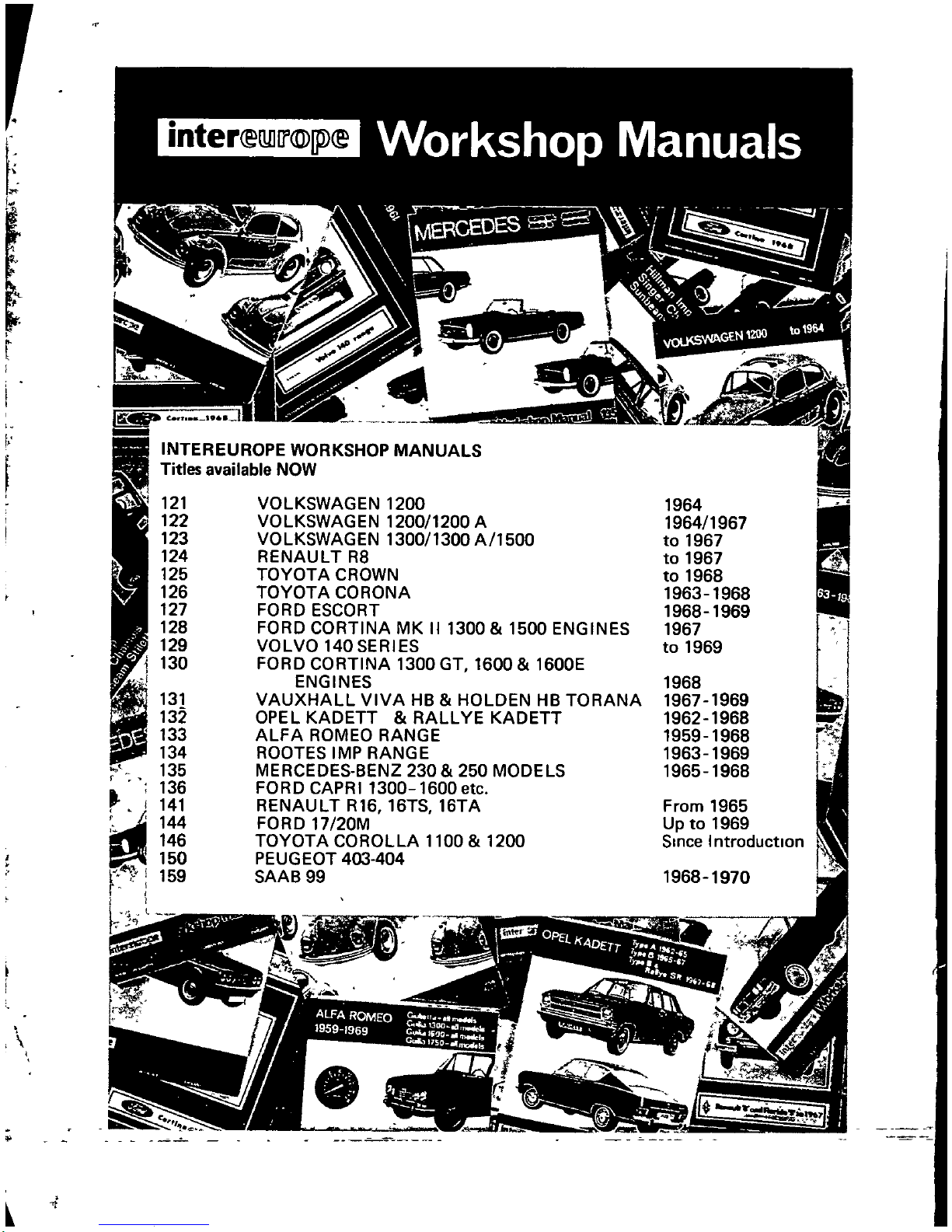
INTER
Titles
121
122
123
124
125
126
127
128
129
130
131
132
133
134
135
136
141
144
146
150
159
EUROPE
available
WORKSHOP
NOW
VOLKSWAGEN
VOLKSWAGEN
VOLKSWAGEN
RENAULT
TOYOTA
TOYOTA
FORD
FORD
VOLVO
FORD
ENGINES
VAUXHALL
OPEL
ALFA
ROOTES
MERCEDES BENZ
FORD
RENAULT
FORD
TOYOTA
PEUGEOT
SAAB
CROWN
CORONA
ESCORT
CORTINA
140
CORTINA
KADETT
ROMEO
IMP
CAPRI
17
20M
COROLLA
403
99
R8
SERIES
VIVA
RANGE
1300
R16
MANUALS
1200
1200
1300
MK
1300
RANGE
16TS
404
1200
1300
II
GT
HB
RALL
230
1600
16TA
1100
A
A
1500
1300 1500
1600
HOLDEN
YE
KADETT
250
MODELS
etc
1200
ENGINES
1600E
HB
TORANA
1964
1964 1967
to
1967
to
1967
to
1968
1963 1968
1968 1969
1967
to
1969
1968
1969
1967
1962 1968
1959 1968
1963 1969
1965 1968
From
Up
Since
1968
1965
to
1969
Introduction
1970
r
I
1
f7
I
C
i
E
L
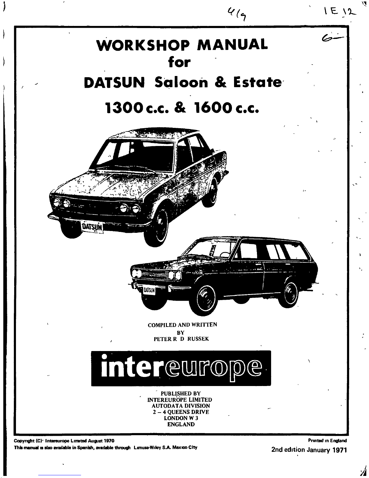
WORKSHOP
MANUAL
for
DATSUN
Saloon
Estate
b
1300
c c
1600 c
c
COMPILED
AND
WRITIEN
BY
PETER
R D
RUSSEK
PUBLISHED
BY
INTEREUROPE
LIMITED
AUTODATA
DIVISION
2
4
QUEENS
DRIVE
LONDON
W
3
ENGLAND
Copyright
IC
IntIInlUrope
LIlDtIld
AulJllt
1970
lb
11
110
IYIIIIbIeinSpanish
av
1Ib1e
thRlUllh
Lan
W
ey
SA
MexICO
City
Pnntlld
n
England
2nd
edition
January
1971
A
r
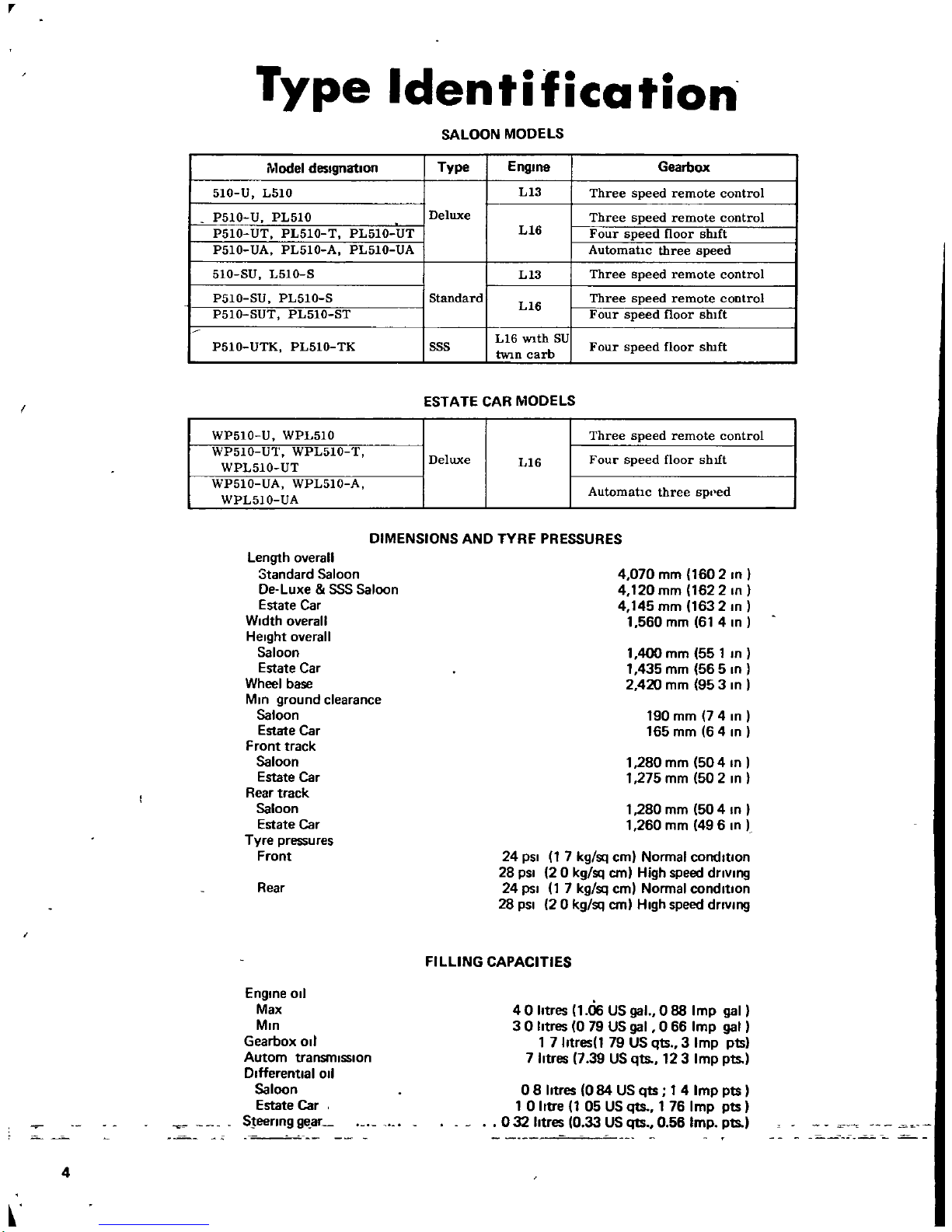
Type
Identification
SALOON MODELS
Model
designation
Type
E
n9108
Gearbox
510
U
L510
L13
Three
speed
remote
control
P510
U
PL510
Deluxe
Three
speed
remote
control
P510
UT
PL510
T
PL510
UT
L16
Four
speed
floor
shIft
P510
UA
PL510
A
PL510
UA
AutomatIc
three
speed
510 SU
L510
S
L13
Three
speed
remote
control
P510
SU
PL510
S
Standard
L16
Three
speed
remote
control
P510
SUT
PL510
ST
Four
speed
floor
shIft
L16
WIth
SU
P510
UTK PL510
TK
SSS
tWIn
carb
Four
speed
floor
sluft
I
ESTATE
CAR
MODELS
WP510
U
WPL510
Three
speed
remote
control
WP510
UT
WPL510
T
Deluxe
Four
speed
floor
shIft
WPL510
UT
L16
WP510
UA
WPL510
A
AutomatIc
three
spl
ed
WPL510
UA
DIMENSIONS
AND
TYRf
PRESSURES
Length
overall
Standard
Saloon
De
Luxe
SSS
Saloon
Estate
Car
Width
overall
Height
overall
Saloon
Estate
Car
Wheel
base
MIO
ground
clearance
Saloon
Estate
Car
Front
track
Saloon
Estate
Car
Rear
track
Saloon
Estate
Car
Tyre
pressures
Front
4
070
mm
1602
10
I
4
120mm 162210
4
145
mm
163210
1
560
mm
61
410
1400mm
551
In
1
435
mm
56
5
In
2
420
mm
953
In
190
mm
74
In
165
mm
64
In
1
280
mm
504
In
1
275
mm
50
2
In
1
280
mm
50
4
In
I
1
260
mm
496
In
Rear
24
pSI
1
7
kg
sq
em
Normal
cornltlon
28
pSI
20
kg
sq
em
High
speed
driVing
24
psi
1
7
kg
sq
em
Normal
condition
28
pSI
20
kg
sq
em
High
speed
driVing
FILLING
CAPACITIES
Engine
011
Max
MIn
Gearbox
011
Autom
transmission
Differential
011
Saloon
Estate
Car
SJeerlng
9e
aL
40htres
uiG
US
gal
0
88
Imp
gal
30htres079
US
gal
0
66
Imp
gal
17htresl79
US
qts
3
Imp
pts
7
htres739
US
qts
123
Imp
pts
08
htres
084
US
qts
1
4
Imp
pts
10htre105
US
qts
1
76
Imp
pts
032
htres1033
US
qts
0
56
Imp
Pts
4
l
INDEX
lYPE
IDENTIFICATION
ENGINE
LUBRICATION
SYSTEM
COOLING
SYSTEM
IGNITION
SYSTEM
FUEL
SYSTEM
CLUTCH
GEARBOX
REAR
AXLE
REAR
SUSPENSION
FRONT
SUSPENSION
STEERING
BRAKES
ELECTRICAL
EQUIPMENT
WIRING
DIAGRAMS
ENGINE
1
JNING DATA
TIGHTENING
TORQUES
CONVERSION
TABLE
4
6
18
20
22
26
36
44
S3
62
68
74
78
86
98
100
101
102
Introduction
This
Workshop
Manual
was
WrItten
wIth
the
IntentIon
of
providIng
the
owner
ofaDatsun
1300
or
1600
and
the
non
franchised
garage
with
detdlls
of
dllthe
maIntenance
and
repalf
operatIOns
that
they
are
hkely
to
encounter
Much
InformatIOn
from
the
manufacturer
s
ongInal
selVlce
and
repalf
Instructions
have
been
condensed
and
Incorporated
m
the
manual
In
a
form
which
will
enable
the
reader
to
qUickly
become
fanfihar
with
the
IdlOsynchrasles
and
techmcahtles
pecuhar
to
the
Datsun
range
of
cars
The
manual
descnbes
the
1300
and
1600
c c
engmes
fitted
to
the Standard
De
Luxe
and
SSS
Saloon
models
and
the
range
of
Estate
Cars
A
complete
hst
of
engme
tumng
data
for
all
models
with
smgle
or
tWIn
carburettors
IS
Included
m
the
manual
There
are
also
separate
secltons
covenng
the
different
types
of
rear
axles
and
rear
suspenSIOns
used
for
the
Sdloon
and
Estate
Car
Models
In
certaIn
cases
It
Will
be
necessary
for
the
reparrer
to
make
use
of
speCial
tools
and
the
appropnate
tool
numbers
and
thelf
methods
of
use
are
either
descnbed
In
the
text
or
can
be
taken
from
Illustraltons
refered
to
m
the
chapter
SpeCial
menlton
should
be
made
of
the
fact
thatafault
findmg
sechon
IS
annexed
to
most
of
the
major
sechons
thus
slmphfymg
the
some
tunes difficult
task
of
diagnOSIS
The
measurement
conversIOns
gIVen
m
mches
have
been
converted
as
closely
as
pOSSIble
from
the
ongInal
mtlhmetre
SIZes
but
It
IS
preferable
to
adhere
to
the
metnc
dunenslons
whenever
pOSSible
A
conversion
tableISmcluded
In
the
manual
and
we
adVise
the
reader
to
cross
reference
With
the
table
when
deahng
With
cnhcal
dlffienslons
We
have
tned
to
make
thiS
manual
as
bnef
as
pOSSible
tllustratmg
rather
than
detailing
the
operahons
Tills
WIll
save
valuable
tnne
and
WIll
also
show
the
reader
Iffimedlately
whether
he
Will
be
able
to
carry
out
the
work
or
not
Expenence
m
prodUCIng
hundreds
of
techmcal
pubhcatIons
for
the
motor
car
manufacturers
and
the
expenence
gamed
by
the
author
who
hunself
was
a skilled
motor
mechamc
for
15
years
has
proven
that
tillsISthe
best
way
for
a
pubhcatlOn
of
thiS
nature
Happy
motonng
and
the
fewer
tnnes
you
have
to
refertotills
book
the
better
for
you
I
The
author
wouldliketothank
for
the
help
and
3SSIStance
gtven
to
bunbyMr
John
Haley
5

inter
llil
@
p
Fog
A2The
removal
of
the
engll
Fog
A
1
Removal
Of
the
cluu
n
slave
cyhllller
or
L
161
engIne
flUBd
10
1
Jb
trel
t
i
n
fd
r
f7
r
if1
0
FIlI
A5Removal
of
the
manifold
assembly
fgA6
eket
FIIA7
Removalofthe
cyhnder
h8I
F
g
A
8
Removalofthe
oil
straaner
6
Engine
INTRODUCTION
The
1300
c c
and
1600
c c
engines
are
4
cylinder
in
line
engines
with
a
single
overhead
camshaft
andafive
beanng
crankshaft
The
1300
and
1600
c
c
engines
differ
only
In
size
The
1600
c c
engine
IS
available
In two
versions
one
of
which
IS
eqUIpped
with
twin
S U
carburettors
with
different
cylinder
head
manifolds
pistons
and
compression
ratio
whereas
the
other
has
a
single
twin
choke
carburettor
ENGINE
Removal
Drain
the
coolant
engine
and
gearbox
011
and
remove
or
disconnect
the
follOWing
parts
Battery
bonnet
air
cleaner
and
rocker
box
breather
hose
radiator
gnll
upper
and
lower
radiator
hoses
radiator
torque
converter
cooling
hoses
from
radiator
automatic
models
only
COIling
fan
and
pulley
fuel
pipe
heater
hoses
If
fitted
accelerator
linkage
choke
cable
wiring
from
starter
motor
alternator
COil
011
pressure
sender
Unit
and
temperature
sender
Unit
Remove
the
clutch
slave
cylinder
Fig
A1and
ItS
return
spnng
Remove
or
disconnect
Speedometer
cable
flat
connector
from
reversing
light
SWitch
gearchange
linkage
front
exhaust
pipe
from manifold
then
the
front
pipe
first
Silencer
and
centre
pipe
assembly
the
propeller
shaftatthe
front
Jack
up
the
gearbox
slightly
and
remove
the
rear
engine
mounting
bracket
the
mounting
crossmember
and
the
handbrake
cable
clamps
Remove
the bolts
secunng
the
front
engine
mounting
brackets
to
the
crossmember
Fit
a
lifting
hooktothe
engine
hangers
and
carefully
11ft
the
engine
and
gearbox
In
a
tilted
poSition
e
g
forwards
and
upwards
uSing
a
SUitable
crane
or
hOIst
FIgA
2
ENGINE
Dismantling
Remove
the
gearbox
and
the
starter
motor
Mark
the
clutch
cover
and
the
flywheel
SUitably
With
a
centre
punch
and
remove
the
clutch
cover
together
With
the
clutch
dnven
plate
Remove
the
follOWing
parts
Alternator
and
bracket
engine
mountings
011
filter
water
drain
plug
011
pressure
SWitch
Mount
the
engine
In
a
SUitable
stand
If
available
Special
Tool
ST37200510
attachment
and
Stand
ST37100000
See
Flg
A3
Remove
thedIStnbutor
cap
together
With
the
spark
plug
leads
unscrew
the
spark plugs
and
remove
the
dlstnbutor
Remove
the thermostat
hOUSIng
FIgA
4
Remove
the
inlet
and
exhaust
manifolds
Flg
A
5
Remove
the
crankshaft
pulley
Remove
the fan
pulley
and
the
water
pump
fuel
pump
and
rocker
cover
Remove
the
fuel
pump
drive
cam
and
the
crankshaft
sprocket
FlgA
6
Remove
the
cylinder
head
assembly Fig
A
7
USing
special
wrench
ST49010000
for
removing
the
cylinder
h
llJd
bolts
Turn
the
engine
over
and
remove
the
sump
and
the
Internal
011
strainer
Fig
A
8
timing
chain
cover
chain
tensloner
and
timing
chain
Remove
the
011
thrower the
crankshaft
wonn
gear
and
the
chain
dnve
sprocket
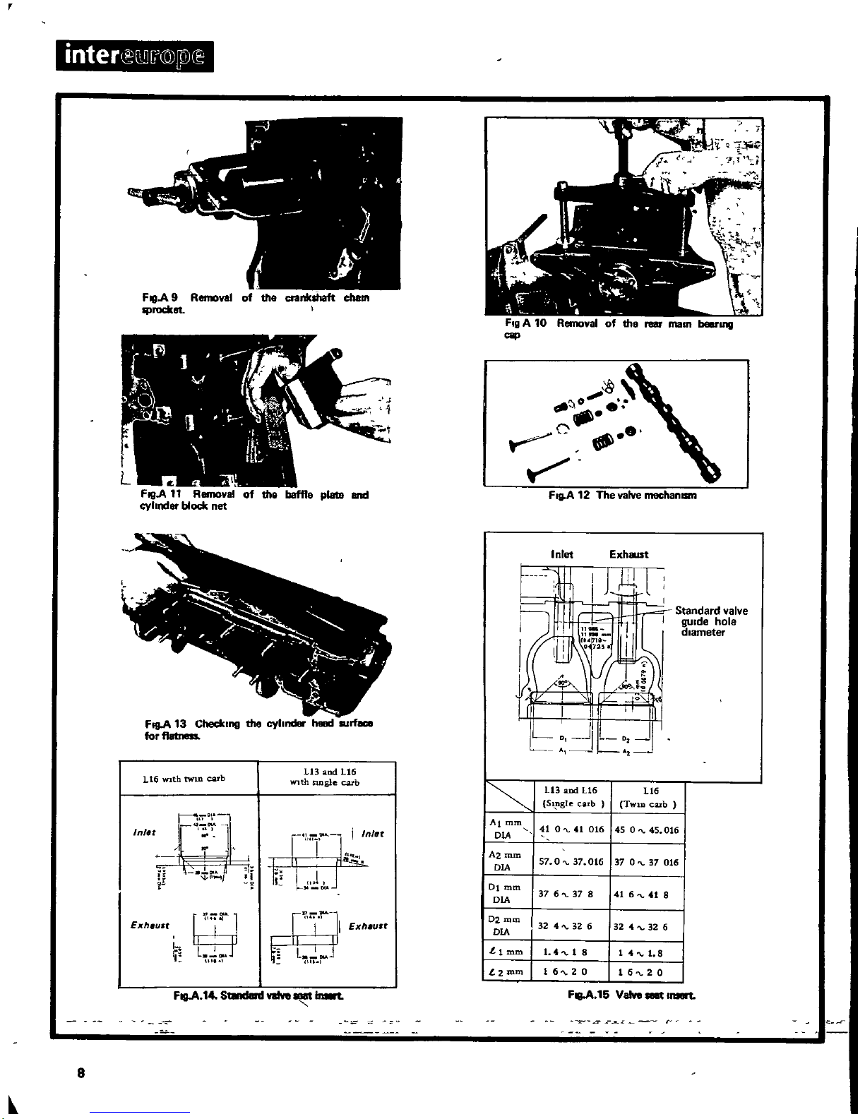
FIgA
9
Remove
the
big
end
beanng
caps
pistons
and
connecting
rod
assemblies
keeping
them
In
sets
In
the
correct
assembly
order
Remove
the
flywheel
and
the
main
beanng
caps
uSing
a
special
tool
ST44630000
for
the
rear
main
beanng
cap
Fig
A
11
Remove
the
rear
011
seal
and
11ft
out
the
crankshaft
Remove
tne
baffle
plate
and
the
cylinder
block
net
FIgA
11
Remove
the
piston
nngs
WithaSUitable
piston
nng
expander
and
the
gudgeon
pin
WithaSUitable
mandrel
the
outer
diameter
of
which
should
not
exceed
the
diameter
of
the
piston
pin
and
a
handpress
ThereISalso
special
tool
ST4484000D
Remove
the
valve
rocker
springs
loosen
the rocker
piVOt
lock
nuts
and
remove
the
rocker
anns
by
presSing
down
the
valve
spnngs
Remove
the
camshaft
taking
care
not to
score
the
camshaft
bushes
Remove
the
valves
Withaconventional
valve
lifter
Fig
A
12
ENGINE
Inspection
and
Overhaul
Thoroughly
clean
all
parts
of
dirt
011
and
water
scale
before
inspection
and
before
attempting
to
carry
out
overhaul
operations
Blowout
all
passages
With
compressed
air
Remove
carbon
depOSits
from
the
top
of
the
pistons
combustion
chambers
cylinder
head and
valves
but do
not
remove
metal
from
any
of
the
parts
I
nspect
and
overhaul
the
parts
as
follows
Cylinder
head
Check
cylinder
head
for
cracks
and
the
mating
faces
for
burrs
or
uneveness
and
replace
If
necessary
note
that
different
cylinder
heads
are
used
for
the
Single
and
twin
carburettor
verSions
of
the
1600
c
c
engine
Check
the
mating
surface
for
flatness
by
means
of
a
straight
edge placed
across
the
head and
checking
the
clearance
Withafeeler
gauge
FgA 13
If
the
clearance
exceeds10
mm
0
0039
In
regrind
the
cylinder
headtoblock
face
Check
the
valve
seats
for
damage
or
wear
and
If
necessary
reface
In
accordance
With
the
dimenSions
given
In
Fig
A14andA15
If
necessary
replace
valve
Inserts
To
replace
the
Inserts
bore
out the
old
Insert
and
select
the
correct
Insert
Fig
A
16
and
fit
by
heating
the
cylinder
headto150
200oC
300
3900F
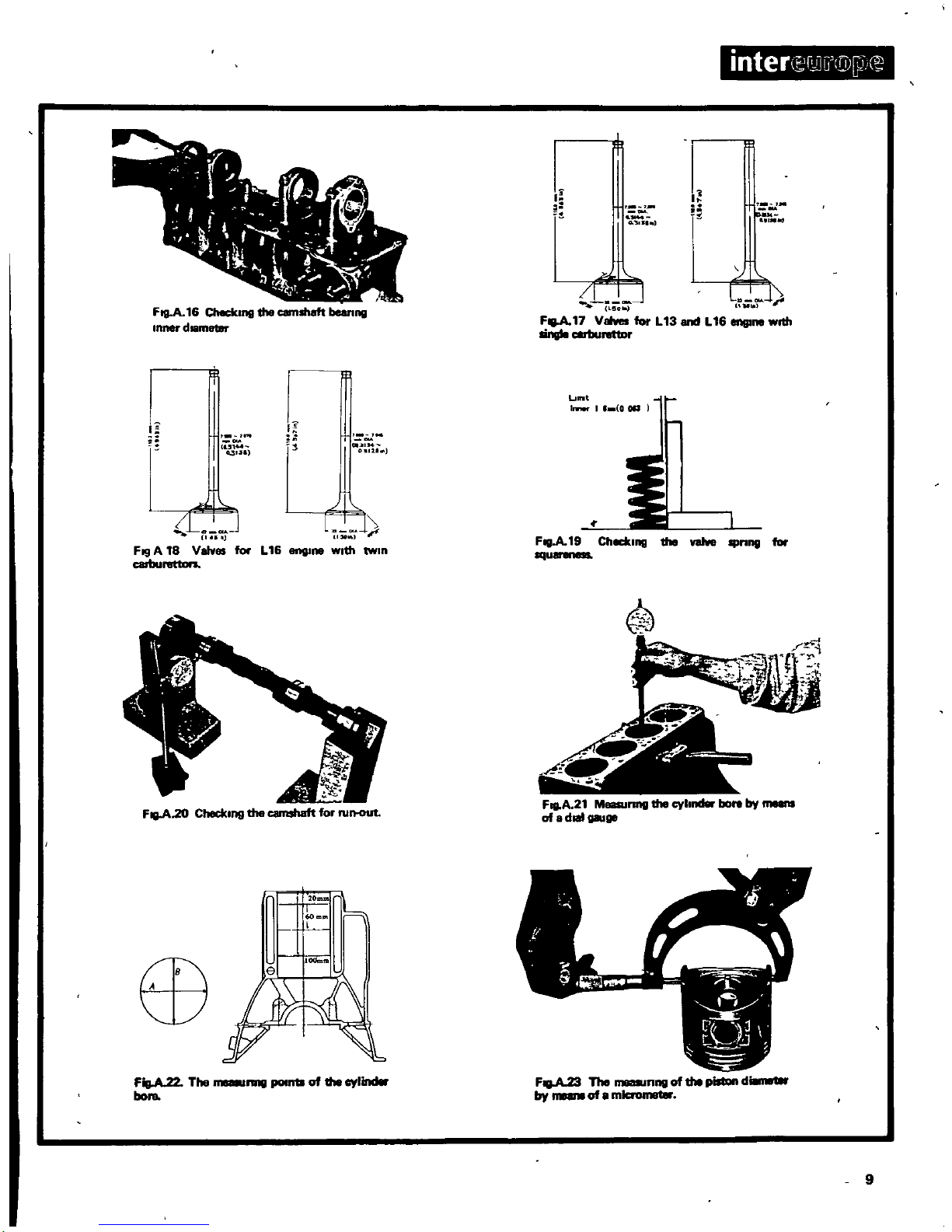
Valve
guides
USing
micrometers
Internal
and
external
che
the
tolerance
between
the
valve
stems
and
the
valve
gUides
ThiS
clearance
must
not
exceed
0048
mm
00019
In
for
Inlet
valves
and
0
073
mm
00029
In
for
exhaust
valves
An
easy
way
of
checking
the
clearance
IS
to
Insert
the
valve
stem
Into
the
gu d
7
r
inter
E2C0
@
0
F
FillA
9
Removal
of
the
crankshaft
challl
rocket
1
1
FillA
11
Removal
of
the
baffle
plata
and
cyhrder
block
net
o
S
0
cf
FI
A
12
Inlet
Exhal51
FIllA
13
Checlul19
the
cyhnder
heud
rt
forfl
Standard
valve
gUIde
hole
diameter
L16
WIth
twin
carb
Ll3
and
Ll6
With
SIngle
cub
U3
and
L16
Ll6
S
gle
cub
TWlD
cub
Almm
410
41016
450
45 016
DIA
Azmm
57
0
37
016
37
O
37 016
DIA
Dlmm
37
6
37 8 41 6
41 8
DIA
D2mm
324
326
DIA
324
326
Llmm
141
8
1 1
8
t
2mm
1620
16
20
FIllA
15
VeIve
to
Inl
t
F
Q
OtA
J
I
Inl
r
i
1
DIA
r
Ex
heult
r
r
1
I
I
IlIt
1
I
ExheuU
La
IlIA
HU
1
FIlIA
14
St8nd8nI
valve
Il8
inwt
8
i
nte
ferbiGD
W
J
r
rrt
l
I
8
r
I
I
r
J
D
I
r
T
010
0
51
01
FI9
A16Ch
c1ung
the
camshaft
beanng
Inner
d
r
F
17
V
far
L
13
andL16
wrth
IingIo
rettD
lm
I
11
0011
II
0
11
5144
031
51
j
l
CII
IM
l11
J
Fig
A
18
Valves
farL16
Ill
wIth
twIn
C81bunmon
FIlIA19
CheckIng
the
valve
IIInng
for
squ
F
A
21
MlI8SUnng
the
cyl
bore
by
of
8
doallllU98
FigA22
The
nne
JIlIIII18
of
the
cyllncllr
bora
F
The
nng
of
the
pilllln
d
by
of8mlcrom8lar
9
ImII
B
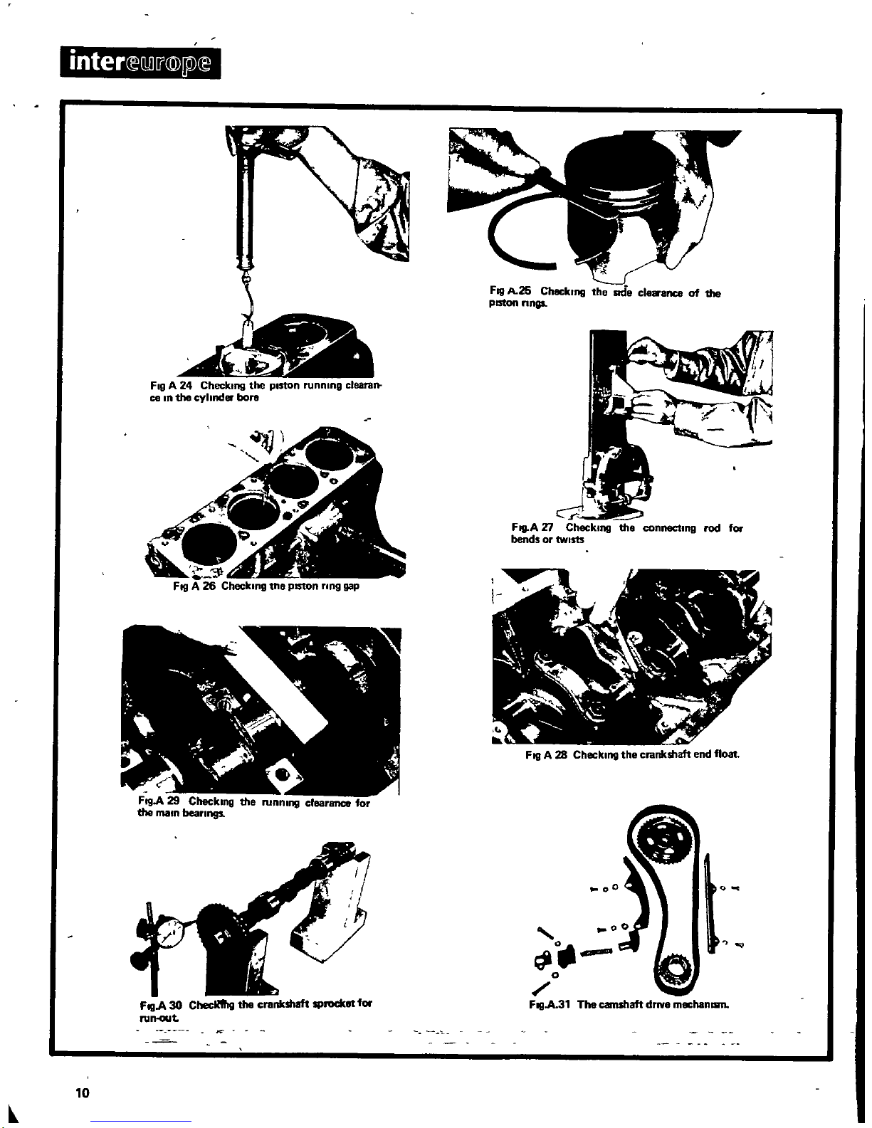
FIgA24
CheckIng
the
pIston
runnIng
clearan
ce In
the
cyhnd
bore
FI9A
29
CheckIng
the
running
clearance
for
the
maIn
beaFlngs
FogA
30
Checlllllg
the
crenkshaft
sprocklJt
for
FUIHlllt
10
Fog
A
26
CheckIng
the
ade
cl
ence of
the
pISton
Flngs
Ftg
A
Xl
CheckIng
the
connectIng
rod
for
bends
or
twIsts
FillA28
CheckIng
the
crankshaft
end
float
0
o
FogA31
The
camshaft
drIVe
mechanam
I
and
move
It
from left
to
nght
If
thiS
movement
exceeds
0 2
10m
0
0079
10
1
the
guide
needs
replacmg
When
replacmg
valve
gUides
press
out
the
old
gUide
and
press
10
the
new
gUide
after
the
cylinder
head
has
been
heated
to
150
2000C
300
3
JOOF
Valve
gUides
are
available
10
oversize
of
02
10m
00079
10
1
Fmally
ream
the
valve
gUide
to
the
dimenSion
of
the
valve
stem
observmg
the
specified
running
clearance
between
gUide
and
stem
Valves
Check
the
valve
face
for
pitS
grooves
scores
and
other
damage
Check
the
stem
for
distortion
and
wear
When
mspectmg
the
valve
heads
check
10
particular
for
burrs
cracks
and
corrosion
If
the
valve
head
edge
IS
worn
down
to
0
20 10
0 5
10m
replace
the
valve
If
necessary
gnnd
the
valve
on
a
valve
gnndlng
machine
taking
off
only
enough
matenal
to
remove
pitS
and
grooves
The
valve
dimenSions
are
shown
In
Fig
A17andA18
Valve
sprmgs
Measure
the
free
length
of
the
valve
springs
and
replace
If
less
than
speCified
Also
test
the
valve
sprong
pressure
Check
the
valve
sprongs
for
distortion
by
plaCing
a
steel
square
on
to
a
surface
plate
PosItion
the
spnng
against
the
square
edge
and
slowly
rotate
the
spring
The
clearance
between
the
top
of
the
sprmg
and
the
edge
should
not
exceed16
10m
0063
10
Fig
A
191
The
valve
spnng
specifications
are
given
In
section
TECHNICAL DATA
Camshaft
Measurethe
InSide
diameter
of
the camshaft
bearings
and
the
outside
diameter
of
the
camshaft
Journals
and
If
wear
IS
found
inSide
the
blackets
replace
the
cylinder
head
assembly
The
wear
limitISC
1
10m
00039
In
1
Check
the
camshaft
for
wear
and
damage
andIfthese
exceed
the
limits
given
In
sectIOn
TECHNICAL DATA
replace
the
camshaft
The
camshaft
runout
can
be
checked
as
shown
In
Fig
A 20
The
Indication
on
the
dial
gauge
should
not
exceed
005
10m
0002010
Cylmder
block
Visually
check
the
block
for
flaws
and
cracks
Check
the
mating
surface
the
same
way
as
the
cylinder
head
and
If
the
deViation
exceeds01
mm
0
0039
In
regnnd
the
block
Cylinder
bore
Check
the
cylinder
bores
for
excessive
wear
ovallty
and
taper
FlgA
211The
measunng
pOInts
for
the
cylinder
bores
are
shown
10
Fig
A 22
If
the
bores
are
Within
the
limits
remove
the
carbon
depOSit
ridge
at
the
top
of
the
cylinder
bore
USing
a
SUitable
tool
The
specifications
are
given
10
section
TECHNICAL DATA
Rebormg
cyhnders
When
rebonng
all bores
must
be
done
at
the
same
time
As
a
speclahsed
workshopISdealing
With
operations
of
thiS
nature
It
IS
necessary
to
mfonn
the
workshop
of
thiS
procedure
Five
oversize
piston
sets
are
available
and
are
hsted
10
section
TECHNICAL DATA
To
obtain the
fmlshed
bore
Size
measure
the
piston
across
Its
skirt
as
shown
10
FlgA
23
and
add
the
average
valueofthe
piston
to
cylinder
clearance
When
the
cyhnder
bores
have
been
finish
honed
check
the
piston
cyhnder
clearance
as
shown
In
Fig
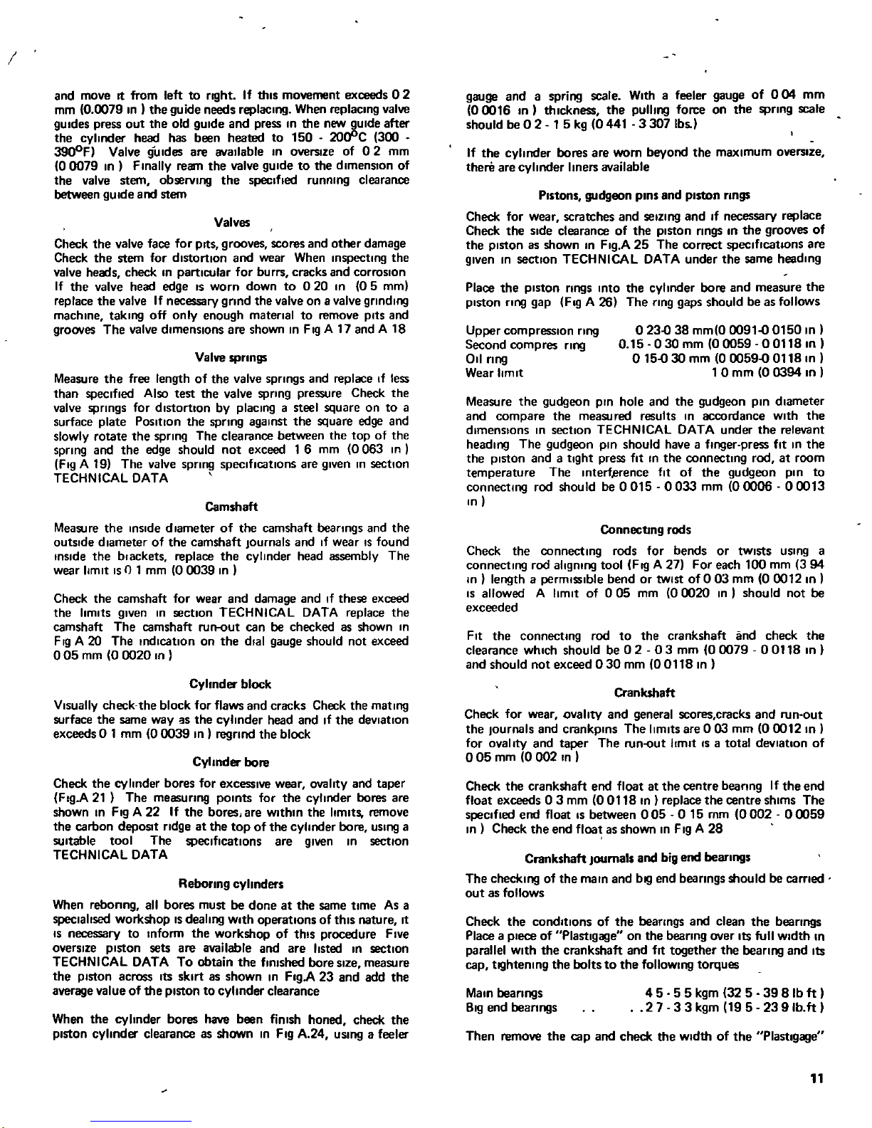
A
24
usmg
a
feeler
gauge
and
a
spring
scale
Withafeeler
gauge
of 004
10m
00016
10
1
thickness
the
pullmg
force
on
the
spnng
scale
should
be
0215
kg
0441
3307
Ibs
1
If
the
cyhnder
bores
are
worn
beyond
the
maximum
oversize
there
are
cyhnder
hners
available
Pistons
gudgeon
pins
and
piston
rmgs
Check
for
wear
scratches
and
seiZing
and
If
necessary
replace
Check
the
Side
clearance
of
the
piston
nngs
10 the
grooves
of
the
piston
as
shown
10
FIgA 25
The
correct
specificatIOns
are
given
In
section
TECHNICAL DATA
under
the
same
head
109
Place
the
piston
nngs
mto
the
cyhnder
bore
and
measure
the
piston
nng
gap
Fig
A
261
The
nng
gaps
should
beasfollows
Upper
compression
nng
Second
compres
ring
011
nng
Wear
limit
023
0381010
0009100150
In
1
0 15
030mm
00059
00118101
o15030
mm
00059
0011810
1
0
mm
0
0394
In
Measure
the
gudgeon
prn
hole
and
the
gudgeon
pm
diameter
and
compare
the
measured
results
10
accordance
With
the
dimenSions
In
section
TECHNICAL
DATA
under
the
relevant
heading
The
gudgeon
pin
should
have
a
finger
press
fit In
the
the
piston
and
a
tight
press
fit In
the
connecting
rod
at
room
temperature
The
Interf
erence
fit
of
the
gudgeon
pin
to
connecting
rod
should
be
0015 0033
10m
00006
00013
In
Connecting
rods
Check
the
connecting
rods
for
bends
or
twistS
uSing
a
connecting
rod
aligning
tool
FI
I
A 27
For
each
100
10m
394
In
length
a
permiSSible
bend
or
twist
of003
mm
0
0012
In
IS
allowed
A
limit
of
005
10m
00020
In
should
not
be
exceeded
Fit
the
connecting
rod
to
the
crankshaft
and
check
the
clearance
which
should
be
02
03
mm
00079
00118
In
1
and
should
not
exceed030
10m
0011810
1
Crankshaft
Check
for
wear
ovahty
and
general
scores
cracks
and
run
out
the
Journals
and
crankplns
The
limitS
are
0
03
10m
00012
In
for
ovallty
and
taper
The
runout
hmlt
IS
a
total
deViation
of
o
05
10m
0
002
In
Check
the
crankshaft
end
floatatthe
centre
beanng
If
the
end
float
exceeds
03
10m
00118
In
replace
the
centre
shims The
speCified
end
float
IS
between
005
0 15
mm
0002
00059
In
1
Check
the
end
floatasshown
10
Fig
A
28
Crankshaft
Journals
and
big
end
bearings
The
checking
of
the
maIO
and
bl
l
end
beanngs
should
be
carned
out
as
follows
Check
the
conditions
of
the
bearings
and
clean
the
bearings
Place
a
piece
of
Plastlgage
on
the
beanng
over
Its
full
Width
In
parallel
With
the
crankshaft
and
fit
together
the
bearing
and
Its
cap
tl
lhtemng
the
bolts
to
the
follOWing
torques
Main
beanngs
81g
end
bean
ngs
4 5 5 5
kgm
32
5
39
8Ibft
27
33
kgm
195
23
9lb
ft
1
Then
remove
the
cap
and
check
the
Width
of
the
Plastlgage
11
inter
erlLJ
@
Pl
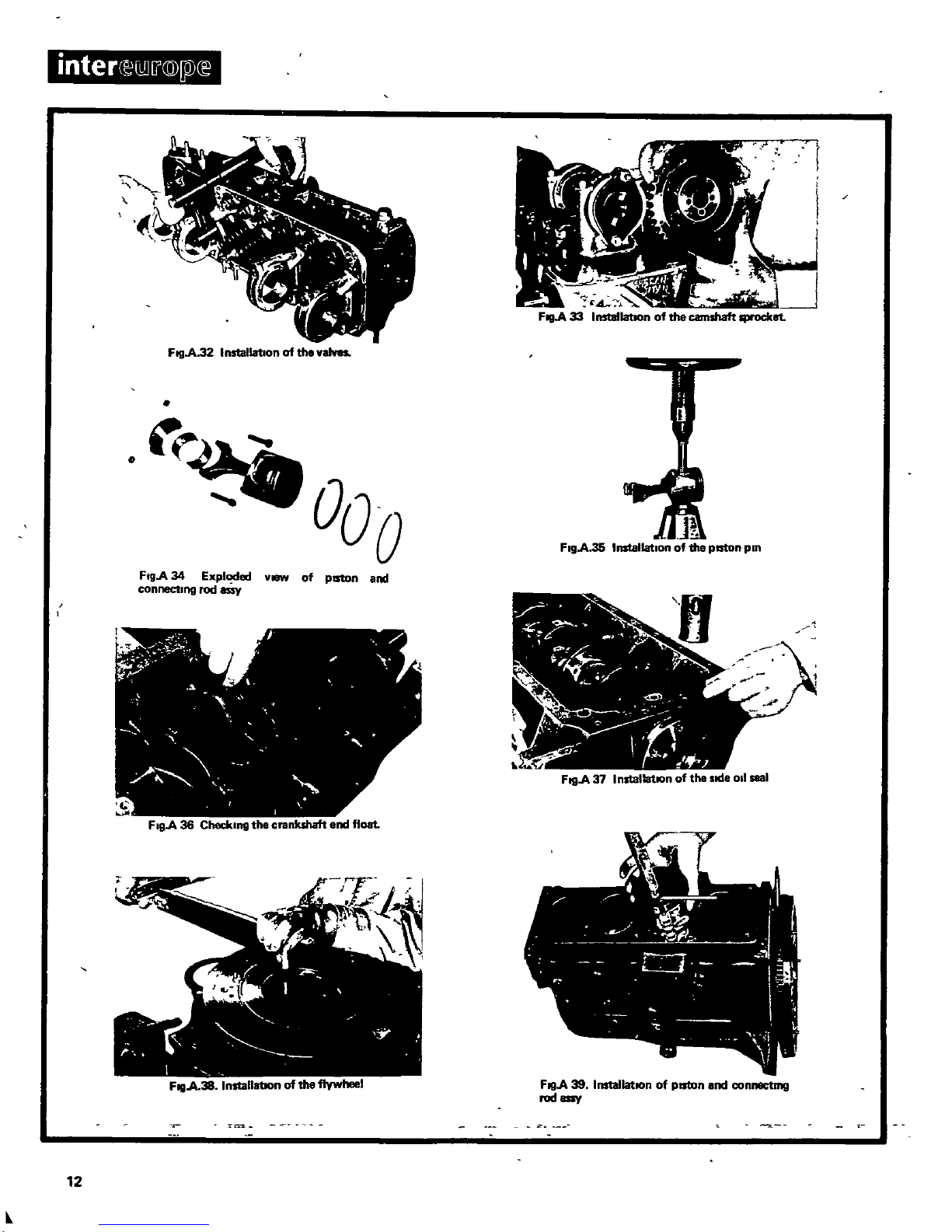
FIlIA
32
InstallatIonofthe
vaJves
ooo
FI9A
34
Expl
ded
VI8W
of
pISton
and
connectIng
rod
FillA
37
InstallatIOn
of
the
sKle
oil
seal
F
19
A
36
Chedung
the
crankshaft
end
float
FIlI
A
38
InstallatIOn
of
the
flywheel
FillA
39
InstallatIOn
of
pISton
end
conllllCtmg
rodaay
12
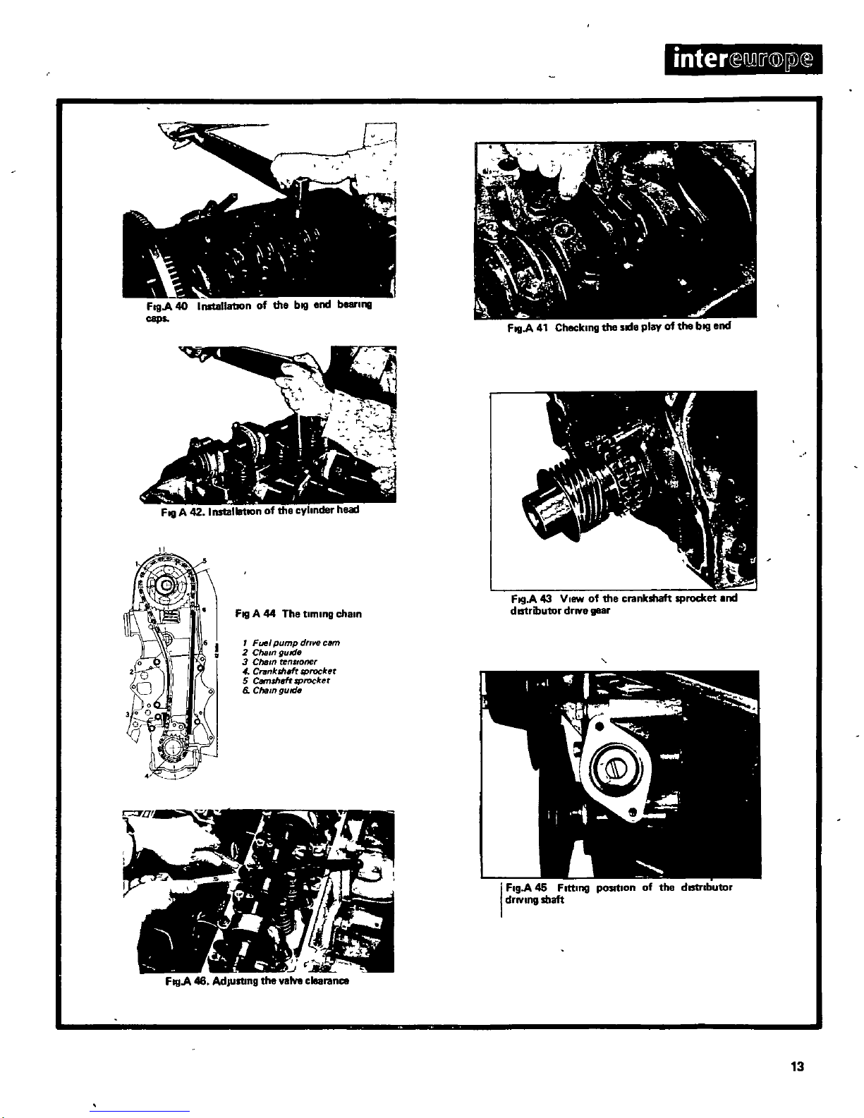
FogA
40
InstallatIOn
of
the
bill
end
beerll18
caps
mter
l
i
@
jlJ
E
t
I
l
ih
s
c
Fill
A
42
InstallatIOn
of
the
cylinder
head
Fill
A44The
tIming
chain
1
Fuel
pump
dflve
earn
2
Cham
guide
3
Cham
nSlone
4
Cntnkshm
sprocket
5
Camshaft
IProcbt
6
Cham
guttie
FillA
41
Checking
the
side
play
of
the
bill
end
FogA
43
V
1fW
of
the
crankshaft
sprocket
end
dIStributor
drive
geer
FillA46AdjUsting
the
valve
clearance
I
FlgA
45
FIttIng
pOSItIon
of
the
dIStrIbutor
drIVing
slIaft
13
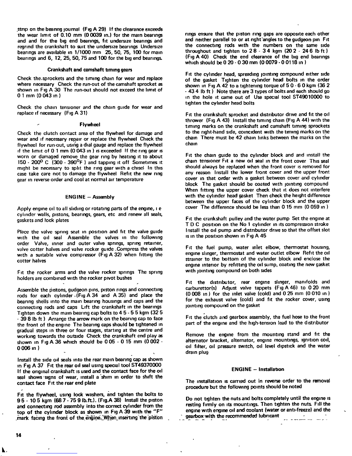
stnp
on
the
beanng
Journal
FIQ
A 29
If
the
clearance
exceeds
the
wear
limit
of010
mm
00039
In
for
the
main
beanngs
and and
for
the
big
end
beanngs
fit
undersize
bearings
and
regrind
the
crankshaft
to
SUit
the
undersize
bearings
Undersize
bearings
are
available
In
1
1000
mm
25 50 75
100
for
main
bearings
and
6 12
25
5075and 100
for
the
big
end
bearings
Crankshaft
and
camshaft
timing
gears
Check
the
sprockets
and
the
tlmll19
chain for
wear
and
replace
where
necessary
Check
the
run
out
of
the
camshaft
sprocket
as
shown
In
Fig
A
30 The
run
out
should
not
exceed
the
limit
of
o
1
mm
0
043
In
Check
the
chain
tenslOner
and
the
chain
gu
Ide
for
wear
and
replace
If
necessary
Fig
A
31
Flywheel
Check
the
clutch
contact
area
of
the
flywheel
for
damage
and
wear
and
If
necessary
re
alr
or
replace
the
flywheel
Check
the
flywheel
for
run
out
uSing
a
dial
gauge
and
replace
the
flywheel
If
the
limit
of01
mm
0043
In
IS
exceeded
If
the
ring
gear
IS
worn
or
damaged
remove
the
gear
ring
by
heating
It
to
about
150
2000
C
300
3900F
and
tapping
It
off
Sometimes
It
might
be
necessary
to
split
the
ring
gear
Withachisel
In
thiS
case
take
care
notto
damage
the
flywheel
Refit the
new
ring
gear
In reverse
order
and
coolatnormal
air
temperature
ENGINE
Assembly
Apply
engine
011toall
sliding
or
rotating
parts
of
the
engine
I
e
cylinder
walls
pistons
bearings
gears
etc
and
renew
all
seals
gaskets
and
lock
plates
Place
the
valve
spring
seat
In
poSition
and
fit
the
valve
gUide
With
the
011
seal
Assemble
the
valves
In
the
follOWing
order
Valve
Inner
and
outer
valve
springs
spring
retainer
valve
cotter
halves
and
valve
rocker
gUide
Compress
the
valves
With
a
suitable
valve
compressor
Fig
A 32
when
fitting
the
cotter
ha
lves
Fit
the rocker
arms
and
the
valve
rocker
springs
The
Spring
holders
are
combined
With
the rocker
pivot
bushes
Assemble
the
pistons
gudgeon
pinS
piston
rings
and
connecting
rods
for
each
cylinder
Fig
A 34
and
A 35
and
place
the
bearing
shells
Into
the
main
bearing
hOUSings
and
caps
and
the
connecting
rods
and
caps
Lift
the
crankshaft
In
the
bearings
Tighten
down the
main
bearing
cap
bolts
to
4 5
55
kgm
325
39
8
lb
ft
Arrange
the
arrow
mark
on
the
bearing
cap
to
face
the
front
of
the
engine
The
bearing
caps
shouldbe
tightened
In
gradual
steps
In
three
or
four
stages
starting
at
the
centre
and
working
towards
the
outside
Check
the
crankshaft
end
playas
shown
In
Fig
A 36
which
should
be
005 015
mm
0002
00061n
Install
the
Side
011
seals
Into
the
rear
main
bearing
cap
as
shown
In
Fig
A 37
Fit
the
rear
011
seal
uSing
special
tool
ST49370000
If
the
Original
crankshaft
IS
used
and
the
contact
face
for
the
011
seal
shows
slgns
of
wear
Installashim
In
order
to
shift
the
contact
face
FItthe
rear
end
plate
Fit
the
flywheel
USing
lock
washers
and
tighten
the
bolts
to
95
105
kgm
68
7
75
9Ib
ft
I
Flg
A
38
Install
the
piston
and
connecting
rod
assembly
into
the
correct
cylinder
from the
top
of
the
cylinder
block
as
shown
In
Fig
A39with
the
F
mark
faCing
the
front
of
the
e
gi
le
W
h
en
lnsertlng
the
piston
14
rings
ensure
that the
piston
ring
gaps
are
opposite
each
other
and
neither
parallel
toorat
nght
angles
to
the
gudgeon
pin
Fit
the
connecting
rods
With
the
numbers
on
the
same
Side
throughout
and
tighten
to
2 8 3 4
kgm
20
2
246lb
ft
Fig
A
40
Check
the
end
clearance
of
the
big
end
bearings
which
should
be 0
20
030
mm
00079
00118
In
I
Fit
the
cylinder
head
spreading
JOinting
compound
either
Side
of
the
gasket
Tighten
the
cylinder
head
borts
In
the
order
shown
In
Fig
A 42
to
a
tightening
torque
of
5 0
60
kgm
36
2
434Ib
ft
Note
there
are
3
types
of
bolts
and
each
should
go
In
the
hole
It
came
out
of
Use
special
tool
ST49010000
to
tlQhten
the
cylinder
head
bolts
Fit
the
crankshaft
sprocket
and
distributor
drive
and
fit
the
011
thrower
Fig
A 43
Install
the
timing
chain
Fig
A 44
With
the
timing
marks
on
the
crankshaft
and
camshaft
timing
sprockets
to
the
right
hand
Side
COinCident
With
the
timing
marks
on
the
chain
There
must
be42chain
links
between
the
marks
on
the
chain
Fit
the
chain
gUide
to
the
cylinder
block
and and
Install
the
chain
tensloner
FIt
a
new
011
sealInthe
front
cover
ThiS
seal
should
alwaysbereplaced
when
the
front
cover
IS
removed
for
any
reason
I
nstall
the
lower
front
cover
and
the
upper
front
cover
In
that
order
With
a
gasket
between
cover
and
cylinder
block
The
gasket
should
be
coated
With
JOinting
compound
When
fitting
the
upper
cover
check
that
It
does
not
Interfere
With
the
cylinder
head
gasket
Then
check
the
height
difference
between
the
upper
faces
of
the
cylinder
block
and
the
upper
cover
The
difference
should
be
less
than
0 15
mm
0059
In
Fit
the
crankshaft
pulley
and
the
water
pump
Set
the
engine
at
TDC
position
on
the
No
1
cylinder
In
Its
compressIOn
stroke
Install
the
011
pump
and
dlstnbutor
drivesothat the offset
slot
IS
In
the
position
shown
In
Fig
A 45
Fit
the
fuel
pump
water
Inlet
elbow thennostat
hOUSing
engine
slinger
thennostat
and
water
outlet
elbow
Refit the
011
strainer
to
the
bottom
of
the
cylinder
block
and
enclose
the
engine
interior
by
refIning
the
011
sump
coating
the
new
gasket
With
JOinting
compound
on
both
Sides
Fit
the
distributor
rear
engine
slinger
manifolds
and
carburettor
s
AdjUst
valve
tappets
Fig
A 46
to
020
mm
0008
In
for
the
Inlet
valve
cold
and
025
mm
0010
In
for
the
exhaust
valve
cold
and
fit
the rocker
cover
uSing
JOinting
compound
on
the
gasket
Fit
the
clutch
and
gearbox
assembly
the
fuel
hosetothe front
part
of
the
engine
and
the
high
tenSion
leadtothe
distributor
Remove
the
engine
from the
mounting
stand
and
fit
the
alternator
bracket
alternator
engine
mountings
Ignition
COil
011
filter
011
pressure
SWitch
011
level
dipstick
and
the
water
drain
plug
ENGINE
Installation
The
installation
IS
carned
out
in
reverse
order
to
the
removal
procedure
but
the
follOWing
points
should
be
noted
Do
not
tlQhten
the
nuts
and
bolts
completely
until
the
engine
IS
resting
flnnly
on
Its
mountings
Then
tlQhten
the
nuts
Fill
the
engine
With
engine
011
and
coolant
water
or
anti
freeze
and
the
g
o
with
th
recommended
lubricant
Valve
clearance
hot
Inlet
Exhaust
Valve
clearance
cold
Inlet
Exhaust
Valve
head
diameter
L13and
L16wSC
Inlet
Exhaust
L16wrrC
Inlet
Exhaust
Valve
stem
dla
Inl
Exh
Valve
length
Inlet
Exhaust
Valve
11ft
L13
and
L16wSC
L16
wrrc
Valve
spnng
free
length
113
L16
outer
L16
Inner
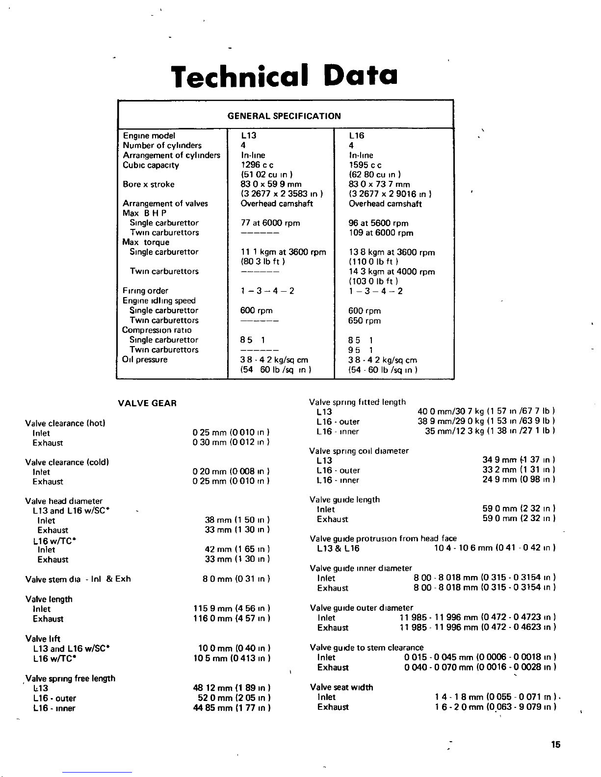
Technical
Data
GENERAL
SPECIFICATION
Engine
model
L13
L16
Number
of
cylinders
4
4
Arrangement
of
cylinders
In
line
In
line
Cubic
capacity
1296
c c
1595
c c
51
02
cu In
62 80
cu In
Borexstroke
830x59
9
mm
830
x 737mm
3
2677x2
3583
In
32677
x
2
9016
In
Arrangement
of
valves
Overhead
camshaft
Overhead
camshaft
MaxBH
P
Single
carburettor
77at6000
rpm
96at5600
rpm
TWin
carbu
rettors
109
at
6000
rpm
Max
torque
Single
carburettor
11
1
kgm
at
3600
rpm
13 8
kgm
at
3600
rpm
803Ib
ft
1100Ib
ft
TWin
carburettors
143
kgm
at
4000
rpm
1030Ibft
Flnng
order
1
3
4 2
1
3 4 2
Engine
Idling
speed
Single
carburettor
600
rpm
600
rpm
TWin
carburettors
650
rpm
Compression
ratio
Single
carburettor
85
1
85
1
TWin
carburettors
95
1
011
pressure
3842
kg
sq
cm
38
4 2
kglsq
cm
54 60
Ib
Isq
In
54 60
Ib
Isq
In
VALVE
GEAR
Valve
spnng
fitted
length
L13
L
16
outer
L16
Inner
400
mm
30
7
kg
1
57
In
167
7
Ib
389
mm
29
0
kg
1
53
In
163
9
Ib
35
mm
12 3
kg
1
38
In
271
Ib
025
mm
0010
In
030
mm
0012
In
020
mm
0008
In
025mm
0010
In
Valve
spnng
COIl
diameter
L13
L16
outer
L16
Inner
34
9
mm
1
37
In
332mm
1
31
In
24
9
mm
0
98
In
38mm
150
In
33
mm
1
30
In
ValveguIde
length
Inlet
Exhaust
59
0
mm
2
32
In
59
0
mm
2
32
In
42
mm
1
65
In
33mm
130
In
80mm
031
In
ValveguIde
protrusIOn
from
head
face
L13 L16
104
106mm
041
0421n
Valve
gUide
Inner
diameter
Inlet
800
8018
mm
0315
03154
In
Exhaust
800
8018
mm
0315
03154
In
1159mm
456In
1160mm
4571n
Valve
gUide
outer
diameter
Inlet
11
985
11
996
mm
0472
04723
In
Exhaust
11
985
11
996
mm
0472
04623
In
100mm
040
In
105mm
0413
In
Valve
guide
to
stem
clearance
Inlet
0015
Exhaust
0040
0045
mm
00006
00018
In
0070
mm
00016
00028
In
4812mm
189In
52
0
mm
2
05
In
44
85
mm
1
77
In
Valve
seat
Width
Inlet
Exhaust
1418
mm
0055
0071
In
1
6 2 0
mm
0
0639079
In
15
r
Valve
seat
angle
Inl
Exh
4J
Valve
seat
Insert
Interference
fit
Inlet
008
0
11
mm
00031
00043
In
Exhaust
006
0 10
mm
00024
00039
In
Valve
gUide
Interference
fit
Inlet
0027
0049
mm
00011
00019
mm
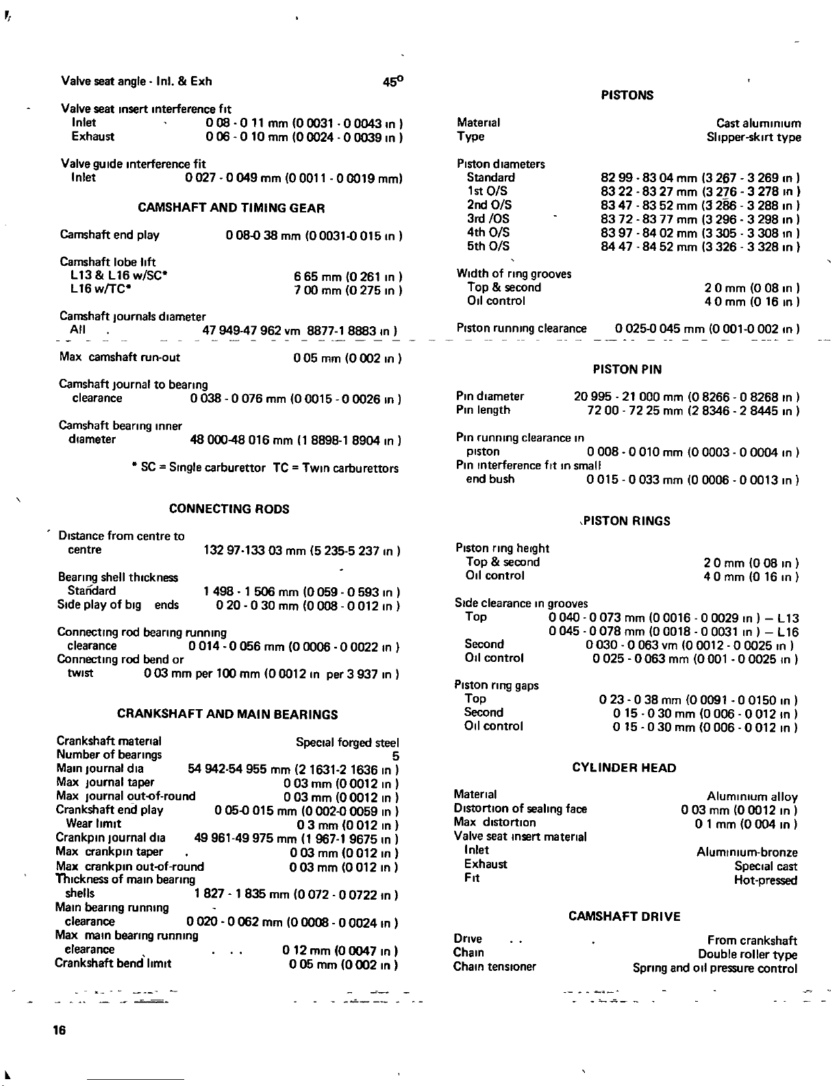
CAMSHAFT
AND
TIMING
GEAR
Camshaft
end
play
o
0838
mm
00031
0
0151n
Camshaft
lobe
lift
L13
L16wSC
L16
w
TC
665
mm
0
261
In
7
00
mm
0
275
In
Camshaft
Journals
diameter
All
47949
47962
vm
887718883
In
Max
camshaft
run
out
005
mm
0002
In
Camshaft
Journal
to
beanng
clearance
0038 0076
mm
00015
00026
In
Camshaft
bearing
Inner
diameter
48
00048016
mm
1
8898
1
8904
In
SC
Single
carburettor
TC
TWin
carburettors
CONNECTING
RODS
Distance
from
centre
to
centre
13297133
03
mm
5235 5237
In
8eanng
shell
thickness
Standard
Side
playofbig
ends
1
498
1
506
mm
0059
0593
In
020 030
mm
0008 0012
In
Connecting
rod
bearing
running
clearance
0014
0056
mm
00006 00022
In
Connecting
rod
bend
or
twist
003
mm
per
100
mm
00012
In
per
3
937
In
CRANKSHAFT
AND
MAIN
BEARINGS
Crankshaft
matenal
Number
of
beanngs
Main
Journal
dla
Max
Journal
taper
Max
Journal
out
of
round
Crankshaft
end
play
Wear
limit
Crankpln
Journal
dla
Max
crankpln
taper
Max
crankpln
out
of
round
Thickness
of
main
beanng
shells
1
827
Main
beanng
running
clearance
0
020
Max
main
bearing
running
clearance
Crankshaft
bend
limlt
Special
forged
steel
5
54
942
54
955
mm
2
1631
2
1636
In
003
mm
00012
In
003
mm
00012
In
o
05015
mm
0
002
0059
In
03
mm
0012
In
49
96149975
mm
1
967
1
9675
In
003mm
00121n
o
03
mm
0
012
In
1
835
mm
0072
00722
In
o
062
mm
0
0008
0
0024
In
o
12mm
00047
In
005
mm
0002
In
16
Matenal
Type
Piston
diameters
Standard
1
st
O
S
2ndOS
3rt
OS
4th O
S
5th O
S
Width
of
nng
grooves
Top
second
011
control
Piston
running
clearance
Pin
diameter
Pin
length
PISTONS
Cast
aluminium
Slipper
sklrt
type
8299
8304
mm
3267
3
269
In
83 22
83
27
mm
3
276
3
278
In
8347
8352
mm
3286
3
288
In
83
72
83
77
mm
3
296
3
298
In
83 97 84
02
mm
3
305
3
308
In
8447
8452
mm
3326
3328
In
2 0
mm
0
08
In
40
mm
0 16
In
o
025045
mm
0001
0002
In
PISTON
PIN
20995
21
000
mm
08266
0
8268
In
72 00 72 25
mm
2
8346
2
8445
In
Pin
running
clearance
In
piston
0008
0010
mm
00003
00004
In
Pin
Interference
fIt
In
small
end bush
0015
0033
mm
00006
00013
In
Piston
nng
heIght
Top
second
011
control
PISTON
RINGS
20
mm
008
In
40
mm
0 16
In
Side
clearance
In
grooves
Top
0040
0073
mm
00016 00029
In
L13
0045
0078mm
00018
000311n
L16
Second
0030
0
063
vm
00012
0
0025
In
011
control
0025
0063
mm
0001
00025
In
Piston
ring
gaps
Top
Second
011
control
Matenal
Distortion
of
sealing
face
Max
distortion
Valve
seat
Insert
matenal
Inlet
Exhaust
Fit
Dnve
Chain
Chain
tensloner
023
038mm
00091 001501n
015
030
mm
0006 0012
In
015
030mm
0006
00121n
CYLINDER
HEAD
Aluminium
alloy
003
mm
00012
In
o
1
mm
0004
In
Aluminium
bronze
Special
cast
Hot
pressed
CAMSHAFT
DRIVE
From
crankshaft
Double
roller
type
Spnng
and
011
pressure
control
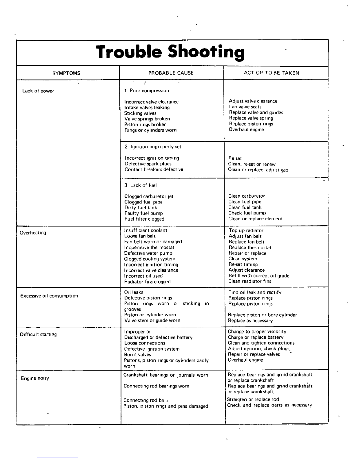
Trouble
Shooting
SYMPTOMS
PROBABLE
CAUSE
ACTIOtJ
TO
BE
TAKEN
I
Lack
of
power
1
Poor
compresSion
Incorrect
valve
clearance Adjust
valve
clearance
Intake
valves
leaking
Lap
valve
seats
Sticking
valves
Replace
valve
andguIdes
Valve
springs
broken
Replace
valve
spring
Piston
rings
broken
Replace
piston
rings
Ringsorcylinders
worn
Overhaul
engine
2
Ignition
Improperly
set
Incorrect
Ignition
limIng
Re
set
DefectIve
spark
plugs
Clean
re
set
or
renew
Contact
breakers
defective
Clean
or
replace
adjust
gap
3
Lackoffuel
Clogged
carburetor
Jet
Clean
carburetor
Clogged
fuel
pipe
Clean
fuel
pipe
Dirty
fuel
tank
Clean
fuel
tank
Faulty
fuel
pump
Check
fuel
pump
Fuel
filter
clogged
Clean
or
replace
element
Overheating
Insufficient
coolant
Top
up
radiator
Looefan
belt
Adjust
fan
belt
Fan
belt
worn
or
damaged
Replace
fan
belt
Inoperative
thermostat
Replace
thermostat
Defective
water pump
Repairorreplace
Clogged
cooling
system
Clean
system
Incorrect
Ignition
liming
Re
set
timing
Incorrect
valve
clearance Adjust
clearance
Incorrect
011
used
Refill
With
correct
oil
grade
Radiator
finS
clogged
Clean
readlator
finS
ExceSSive
oil
consumptIon
Oil
leaks
Fnd011
leak
and
rectify
DefectIve
piston
rings
Replace
piston
rings
Piston
rings
worn
or
sticking
In
Replace
Piston
rll1gs
grooves
Piston
or
cylinder
worn
Replace
piston
or
bore
cylinder
Valve
stem
or
gUide
worn
Replace
as
necessary
D
fficult
starting
Improper
0
1
Change
to
proper
VISCOSity
Discharged
or
defective
battery
Chargeorreplace
battery
Loose
connections
Clean
and
tighten
connections
Defective
Ignition
system Adjust
Ignition
check
plugs
Burnt
valves
RepairOrreplace
valves
PIstons
piston
nngs
or
cylinders
badly
Overhaul
enqlne
worn
Engine
nOIsy
Crankshaft
beanngs
or
Journals
worn
Replace
bearings
and
grind
crankshaft
or
replace
crankshaft
Connecting
rod
bearings
worn
I
Replace
bearings
and
gnnd
crankshaft
or
replace
crankshaft
ConnectIng
rod
be
l
Stralgten
or
replace
rod
Piston
piston
nngs
and
pinS
damaged
Check
and
replace
parts
as
necessary
mterCE
lliJ
@
Plcel
FIg
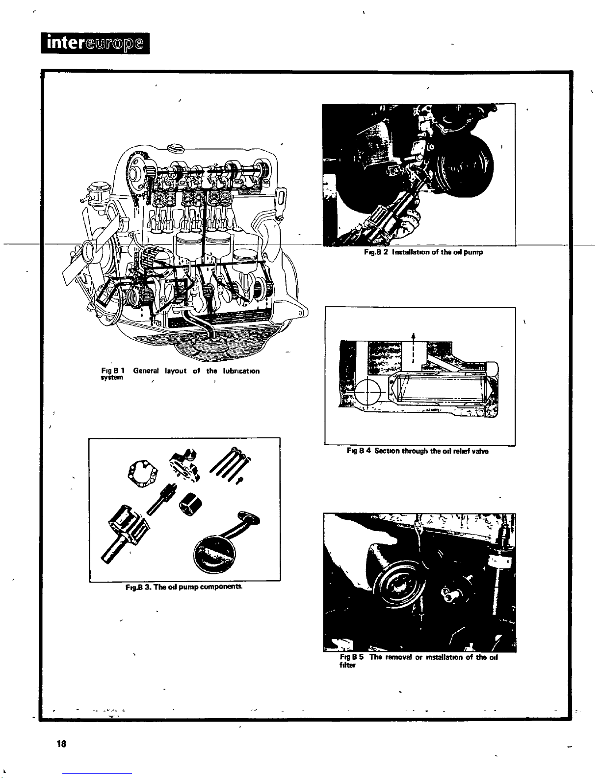
B1General
layout
of
tho
lubricatIOn
system
o
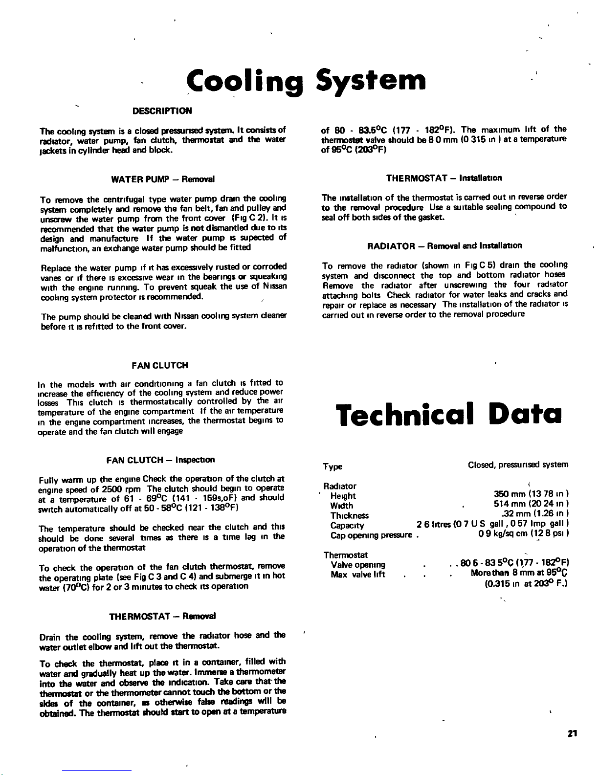
Fig
B
4
SectIOn
through
the0rehefvalvo
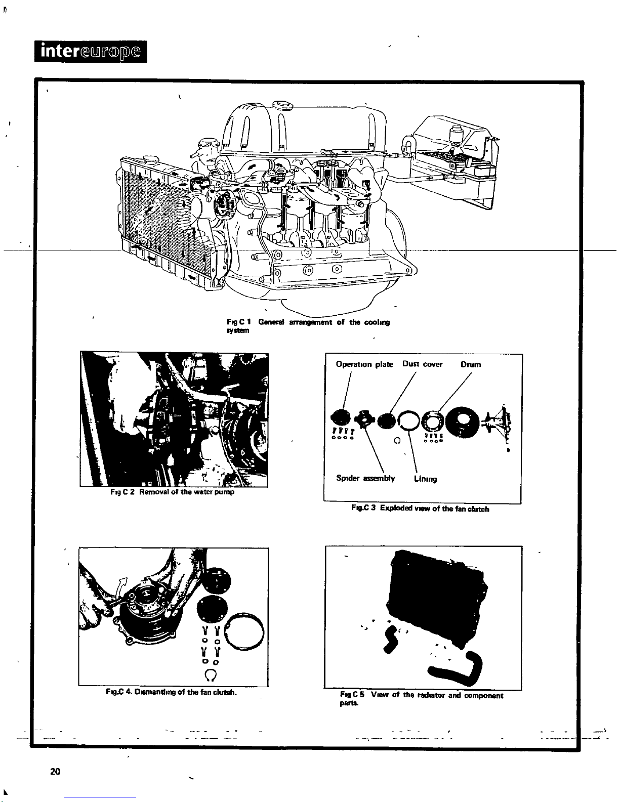
Frg
B3Tho
oil
pump
components
18
Lubrication
System
DESCRIPTION
The
lubricating
system
IS
a
pressure
feed
system
ronslstlng
of
a
rotor
type
011
pump
Inoorpotating
a
regulator
valve
and
driven
by
the
distributor
drive shaft
andafull
flow
011
filter
A
strainer
IS
fined
to
the
bonom
of
the
front
cover
and
serves
the
purpose
to
filter
the
011
before
It
can
reach
the
beanng
locations
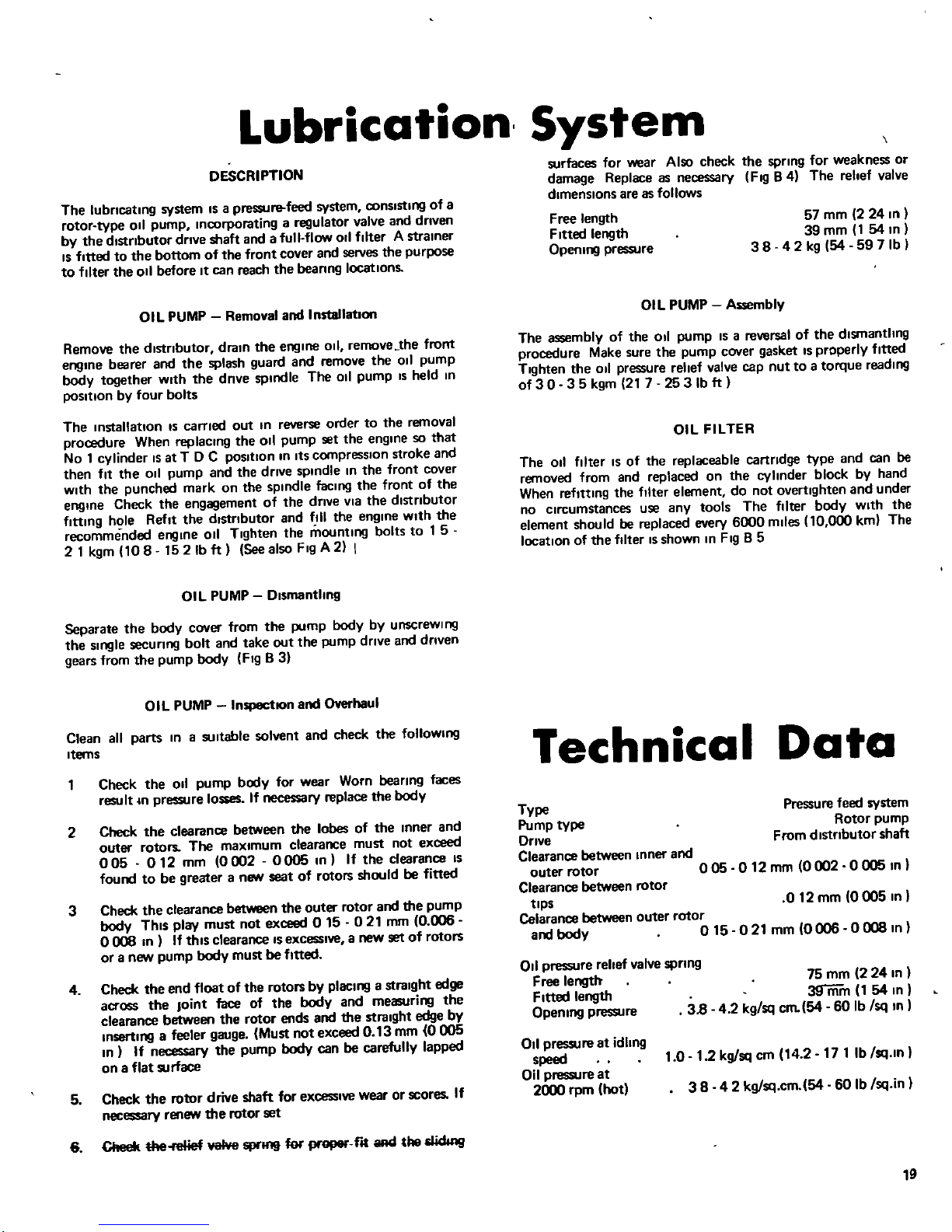
OIL
PUMP
Removal
and
InstallatIOn
Remove
the
distributor
drain
the
engll1e
Oil
remove
the
front
engine
bearer
and
the
splash
guard
and
remove
the
011
pump
body
together
With
the
dnve
spindle
The
011
pump
IS
held
111
poSition
by
four
bolts
The
II1stallatlon
IS
carned
out In
reverse
order
to
the
removal
procedure
When
replaCing
the
011
pump
set
the
engine
so
that
No
1
cylinder
IS
at
T 0
C
position
In
ItS
compression
stroke
and
then
fIt
the
011
pump
and
the
drive
spindle
In
the
front
cover
With
the
punched
mark
on
the
spindle
facing
the
front
of
the
engine
Check
the
engagement
of
the
drive
vIa
the
distributor
fining
hole
Refit the
distributor
and
fill
the
engine
with
the
recommended
engine
011
Tighten
the
mounting
bolts
to
1
5
21kgm
108
1521bft
SeealsoFlgA2
I
OIL
PUMP
Dismantling
Separate
the
body
cover
from the
pump
body
by
unscrewing
the
Single
securrng
bolt
and
take
out
the
pump
drrve
and
driven
gears
from the
pump
body
Fig
B
3
OIL
PUMP
InspectIOn
and
Overhaul
Clean
all
parts
In
a
SUitable
solvent
and
check
the
follOWing
Items
2
Check
the
0
pump
body
for
wear
Worn
bearrng
faces
result
In
pressure
losses
If
necessary
replace
the
body
Check
the
clearance
between
the
lobes
of
the
Inner
and
outer
rotors
The
maximum
clearance
must
not
exceed
005
0
12
mm
0002 0005
In
If
the
clearance
IS
found
to
be
greater
a
new
seat
of
rotors
should
be
fined
3
Check
the
clearance
betWeen
the
outer
rotor
and
the
pump
body
ThiS
play
must
not
exceed
0
15
021
mm
10
006
0008
111
If
thiS
clearance
IS
excessive
a
new
setofrotors
oranew
pump
body
must
be
fined
4
Check
the
end
float
of
the
rotors
by
placingastraight
edge
across
the
Joint
face
of
the
body
and
measuring
the
clearance
between
the
rotor
ends and
the
straight
edge
by
inserting
a
feeler
gauge
IMust
not
exceed
0
13
mm
0005
In If
necessary
the
pump
body
can
be
carefully
lapped
on
a
flat
surface
5
Check
the
rotor
drive
shaft
for
excessive
wear
or
scores
If
necessary
renew
the
rotor
set
6
Cheek
the
fllJief
IiIWe
sprlll
t
for
proper
f
1I
aACI
tile
IidIng
surfaces
for
wear
Also
check
the
spring
for
weakness
or
damage
Replace
as
necessary
FIgB
4
The
rehef
valve
dImenSIons
are
as
follows
Free
length
Fitted
length
Opening
pressure
38
57
mm
2
24
In
39
mm
1
54
In
42
kg
54
597
Ib
OIL
PUMP
Assembly
The
assembly
of
the
0
pump
IS
a
reversal
of
the
dlsmanthng
procedure
Make
sure
the
pump
cover
gasket
IS
properly
fitted
Tighten
the
011
pressure
rehef
valve
cap
nut
to
a
torque
reading
of
3 0 3 5
kgm
21 7
253Ib
ft
OIL
FILTER
The
011
filter
IS
of
the
replaceable
cartridge
type
and
can
be
removed
from
and
replaced
on
the
cylinder
block
by
hand
When
refitting
the
filter
element
do
not
overtighten
and
under
no
circumstances
use
any
tools
The
filter
body
With
the
element
should
be
replaced
every
6000 miles
10
000
km
The
location
of
the
filterISshown
In
Fig
B
5
Technical
Data
Type
Pump
type
Drive
Clearance
between
Inner
and
outer
rotor
0
05
Clearance
between
rotor
tipS
Celarance
between
outer
rotor
and
body
015
Pressurefeed
system
Rotor
pump
From
distributor
shaft
012mmI0
020005111
0
12mm
0005
In
I
021
mm
0006 0008
In
I
011
pressure
rehef
valve
spring
Free
length
Fitted
length
Opening
pressure
38
75
mm
224
In
3fiii
m
1
54
In
4 2
kg
sq
cm
54
60
Ib
sq
In
011
pressure
at
idhng
speed
101
2
kg
sq
cm
14
2 171Ib
sq
ln
Oil
pressure
at
2000
rpm
lhot
38 42
kg
sq
cm
54
60
Ibsqin
19
mter
M
j
@
Pl
Fill
C
1
General
arrangement
of
the
cooling
OY
OperatIon
plate
Dust
cover
Drum
SpIder
assembly
linnl9
FIlI
C
3
Exploded
v
of
the
fan
c1u1l
h
o
V V
00
o
J
FIlI
c4DlSIllantllng
of
thefan
clu1dl
Fill
C 5
V
fIW
of
the
radiator
and
component
parts
20
It
Cooling
System
DESCRIPTION
The
cooling
system
is
a
closed
pressunsed
system
It
consists
of
radiator
water
pump
fan
clutch
thermostat
and
the
water
Jacketsincylinder
head
and
block
WATER
PUMP
Removal
To
remove
the
centrifugal
type
water
pump
drain
the
cooling
system
completely
and
remow
the fan
belt
fan
and
pulley
and
unsaew
the
water
pump
from
the
front
cover
Fig
C2It IS
recommended
that the
water
pump
is
not
dismantled
due
to
Its
design
and
manufacture
If
the
water
pump
IS
supected
of
malfunction
an
exchange
water
pump
should
be
fitted
Replace
the
water
pump
If
It
has
eXce5Slvely
rusted
or
corroded
vanes
or
If
there
IS
excessIVe
wear
In
the
beanngs
or
squeaking
With
the
engine
running
To
prevent
squeak
the
use
of
NIS
8n
cooling
system
protector
IS
recommended
The
pump
should
be cleaned WIth
Nlssan
COOling
system
cleaner
before
It
IS
refitted
to
the
front
cover
FAN
CLUTCH
In
the
models
With
air
conditIOning
a
fan
clutch
IS
fitted
to
IIlCrease
the
effiCiency
of
the
coohng
system
and
reduce
power
losses
ThiS
clutch
IS
thermostatically
controlled
by
the
air
temperature
of
the
engine
compartment
If
the
air
temperature
In
the
engine
compartment
Increases
the
thermostat
beginS
to
operate
and
the
fan
clutch
Will
engage
FAN
CLUTCH
Inspection
Fully
warm
up
the
engine
Check
the
operation
of
the
clutch
at
engine
speed
of
2500
rpm
The
clutch
should
begin
to
operate
at
a
temperatu
re
of
61
690C
141
159soF
and shoo
Id
SWItch
automatically
offat50
580C
121
1380F
The
temperature
should
be
checked
near
the
clutch
and
thIS
should
be
done
several
times
as
there
IS
a
time
lag
In
the
operation
of
the
thermostat
To
check
the
operation
of
the fan
clutch thermostat
remove
the
operating
plate
see
Fig
C3andC4
and
submerge
It
In hot
water
700C
for
2or3
minutes
to
check
Its
operation
THERMOSTAT
R8IllOVlII
Drain
the
cooling
system
remove
the radiator
hose
and
the
water
outlet
elbow
and
11ft
out the
thermostat
To
check
the thermostat
place
It
in a
container
filled
with
water
and
gradually
heat
up
tha
water
Immerseathermometer
into
the
water
and
observe
the
Indication
Taka
C8I
8
that
the
thermostllt
or
the
thermometer
cannot
touch
the
bottom
or
the
sides
of
the
contalller
oth
ise
false
nIlIdinga
will
be
obtained
The
thermostat
should
start
to
open
at
a
temperature
of
80
83
50C
177
182oF
The
maximum
hft
of
the
thermosm
valve
should
be
80
mm
0315
In
at
a
temperature
of
950C
1203oF
THERMOSTAT
Instellatlon
The
installation
of
the thermostat
is
carned
out
In
reverse
order
to
the
removal
procedure
UseaSUitable
sealing
compound
to
seal
off
both
Sides
of
the
gasket
RADIATOR
Removal
and
Installation
To
remove
the
radiator
shown
In
Fig
C
S
drain
the
cooling
system
and
disconnect
the
top
and
bottom
radiator
hoses
Remove
the radiator
after
unscrewing
the
four
radiator
attaching
bolts
Check
radiator
for
water
leaks
and
cracks
and
repair
or
replace
as
necessary
The
installation
of
the
radiator
s
earned
out
In
reverse
ordertothe
removal
procedure
Technical
Data
Type
Closed
pressunsed
system
Radiator
Herght
Width
Thickness
Capacity
Cap
opeOlng
pressure
350
mm
13
78
In
I
514
mm
20
24
In
32
mm
1
26
In
26
IItres
0
7
U
S
gall
057
Imp
gall
I
09
kg
sq
cm
128
pSI
Thermostat
Valve
opening
Max
valve
11ft
80583
SOC
11
7
18
1lF
Morethen
8
mm
at
950C
0
315
In
at
2
30
F
21
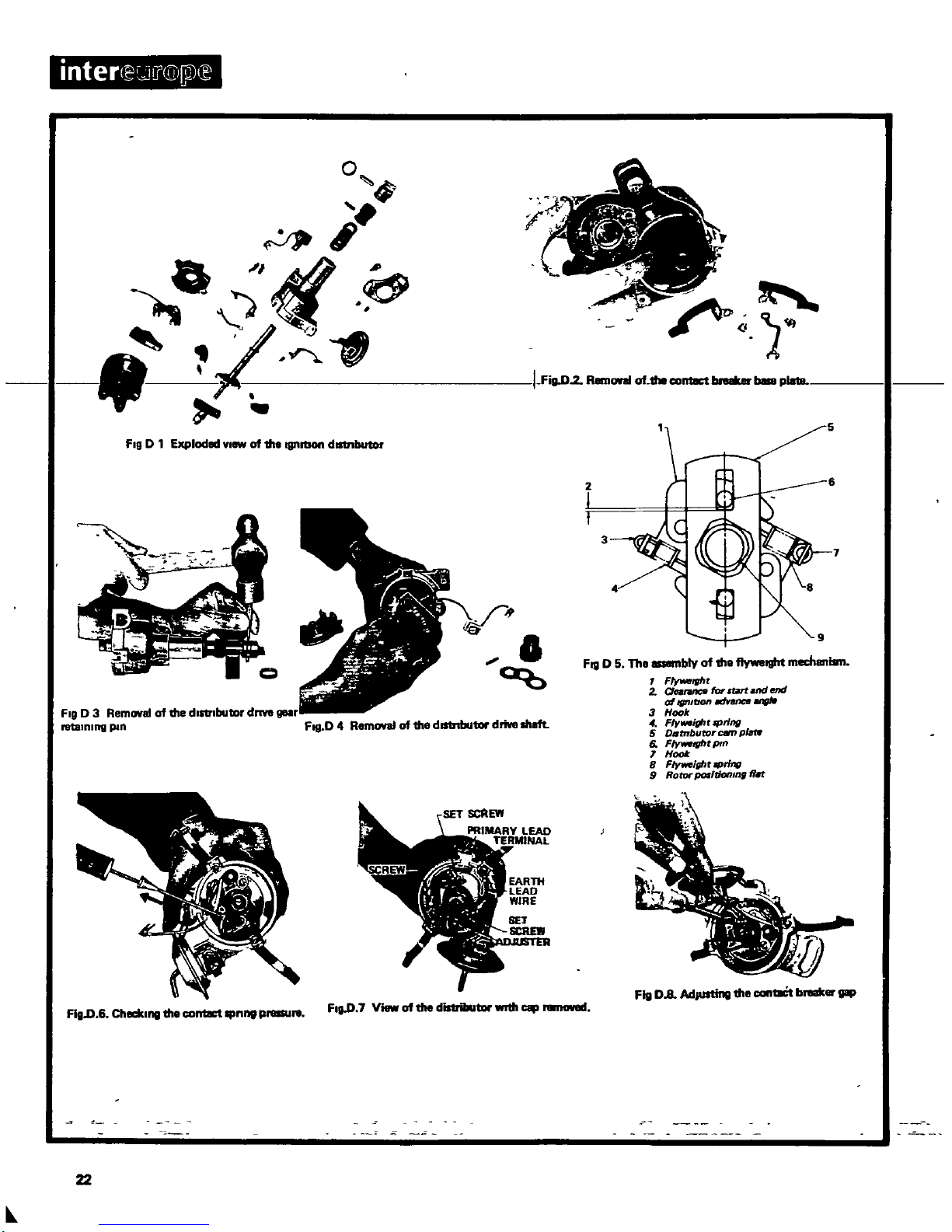
inter
e
l
@Ql
0
0
A
r
FI9
D
1
Explod
YI
of
1118
ognrtlOn
dlltnbutor
v
FI9
D
3
Removal
of
1IIe
dIstrIbutor
drMlllllllr
1111I1Inln9
pin
FItI
D
4
Removal
of
1IIe
dlllnbutar
drive
Iheft
FI9
D
6
Checlull9
1IIe
contact
IlfP
RI
FIg
D
7
Viewof1118
distrillutar
wIth
22
I
FiaD2
Rem
of
the
contact
beI8
plaia
7
FIQ
D
5
The
blyof1118
flyweight
mecherlillll
F
tg
It
2
Oftronco
for
nd
ond
at
IfInltlOll
lranctl
MIIIe
3
Hook
4
Flywo
ght
rprll1l
5
Dtltrrburor
cam
pkrte
6
F
ywetg
lt
pm
1
H
8
Flyweight
rprlnt
9
Rotor
poI
donm
fin
Fig
D
8
AdJUlling
1118
cantBCt
b er
gap
Ignition
System
DESCRIPTION
The
1300
c
c
and
the
1600
c c
engines
With
Single
carburettors
are
fitted
With
the
Ignition
distributor
model
D410
58
whilst
the
1600
c c
engine
With
twin
carburettors
has
model
D400
54
The
outside
appearance
of
both
distributor
models
IS
alike
IGNITION
DISTRIBUTOR
Removal
Disconnect
the
high
tension
cables
from
the
spark
plugs
and
the
Ignition
coli
and
detach
the
primary
wire
from the
distributor
Remove
the
vacuum
pipe
from the
distributor
connection
slacken
the
distributor
clamp
bolt
and
withdraw
the
distributor
IGNITION
DISTRIBUTOR
Dlsmanthng
Remove
the
distributor
cap
and
pull
off
the
rotor
Loosen
the
two
vacuum
Unit
securing
screws
and
11ft
off
the
Unit
Unscrew
the
fixed
contact
POint
set
screw
and
11ft
off
the
pOint
Take
off
the
spring
clip
from the
piVOt
post
of
the
moveable
contact
breaker
pOint
and
remove
the
contact
arm
From
the
Sideofthe
distributor
body
remove
the
two
spring
clips
and
remove
the
contact
breaker
base
plate
see
Fig
D2Take
care
not
to
loose
the
steel
balls
between
the
breaker
spring
and
the
breaker
plate
and
those
between
the
breaker
plates
SUitably
support
the
distributor
shaft
from
underneath
and
drive
out
the
drive
gear
retaining
pin
uSing
a
SUitable
punch
Fig
D
3
Remove
the
gear
and
the
sI1Ims
after
marking
the
relation
of
the
shaft
and
the
gear
and
Withdraw
the
distributor
shaft
from the
other
Side
Fig
D4From
the
InSideofthe
distributor
cam
remove
the
set
screw
and
pull
off
the
cam
Carefully
unhook
the
flyweight
springs
Without
stretching
or
deforming
them
IGNITION
DISTRIBUTOR
Assembly
Thoroughly
clean
all
parts
and
examine
the
distributor
cap
for
cracks
carbon
tracking
and
burnt
or
corroded
terminals
Check
the
carbon
brush
for
excessive
wear
and
If
necessary
remove
defective
parts
Check
the
contact
breaker
gaps
for
pitting
replaCing
them
If
badly
marked
Light
damage
can
be
smoothed
Withan011
stone
Check
the
shaft
for
wear
and
proper
f
It
In
the
body
Check
the
condensor
for
short
or
open
circuits
and
replace
If
necessary
Check
the
vacuum
Unit
for
operation
and
the
flyweight
mechamsm
for
freedom of
movement
The
assembly
isareversal
of
the
removal
procedure
Refer
to
Fig
D5when
assembling
thJ
flyweight
mechamsm
When
the
distributor
isassembled
connect
a
spring
scaleonthe
endofthe
contact
arm
and
slowly
pull
the
spring
scale
lIWay
from the
fixed
contact
POint
Read
off
the
indication
at
the
moment
when
the
arm
is
lust
lifting
from the
fixed
POint
See
FIgD
61
The
correct
valueIS0
50065
kg
1
10143
Ib
Adjust
the
con1llct
breaker
gap
as
described
below
CONTACT
BREAKER
GAP
Adjultment
With
the
distributor fitted
in
reverse
order
to
the
removal
procedure
turn
over
the
engine
until
the
fibre
pad
of
the
contact
breaker
ann
IS
at
the
highest
POint
of
the
distributor
earn
Slacken
the
clamping
screw
at
the
fixed
contact
pOint
and
turn
the
adjuster
screw
Withascrewdriver
untilacontact
gap
of
045 055
mm
0012
0022
In
IS
obtained
Retighten
the
clamping
screw
and
uSing
a
feeler
gauge
rlH
heck
the
contact
breaker
gap
to
ensure
that the
fixed
contact
breaker
plate
has
not
moved
while
the
clamping
screw
was
tightened
The
contact
breaker
POints
can
be
cleaned
by
uSing
a
contact
file
or
an
011
stone
The
raised
areas
on
the
contact
should
be
filed
off
but do
not
attempt
to
remove
the
crater
In
the
other
contact
After
cleaning
the
contacts
they
should
be
placed
opposite
each
other
meeting
over
a
Wide
area
If
the
contacts
only
meet
partially
It
IS
pOSSible
that
overheating
burning
and
sparking
could
develop
A
View
of
the
contact
breaker
assembly
IS
shown
In
Fig
D7The
adjustment
of
the
pOints
IS
shown
In
Fig
D8
IGNITION
TIMING
Adjultment
Remove
the
distributor
vacuum
line
and
start
the
engine
With
the
engine
running
at
Idle
speed
proceed
as
follows
USing
a
stroboscopIC
tlml
ng
light
connected
In
accordance
With
the
instructIOns
of
the
manufacturer
check
that the
timing
case
pOinter
IS
In
line With
the
timing
mark
on
the
crankshaft
which
Will
be made
statIOnary
by
the effect
of
the
timing
IIgt
Each
of
the marks
on
the
crankshaft
pulley
represents
50
of
the
crank
angle
The
tlml
ng
setting
IS
as
follows
1300
c c
engine
1600
c c
w
SC
1600
c c
w
TC
1008
T
DC
1600
rpm
100
8TD C
1600
rpm
1408TDC
650rpm
wlSC
Single
carburettor
w
TC
TWin
carburettor
CHECKING
THE
CENTRIFUGAL
ADVANCE
Disconnect
the
vaaJum
pipe
from the
distributor
hOUSing
paint
a white
line
on
the
crankshaft
pulley
and
start
the
engine
Direct
the
flash
of
the
stroboscopiC
timing
light
on
the
crankshaft
pulley
and
observe
the
movement
of
the white
line
whilst
the
engine
speed
IS
slowly
Increased
The distance
between
the
IgnitIOn
timing
pOinter
on
the
timing
gear
cover
and
the
white
line
should
Increase
noticeably
Incheatlng
a
satisfactory
operation
of
the
centrifugal
advance
mechanism
If
the
paint
marks
appears
to
move
back
and
forth
In
an
Irregular
manner
It
may
be
that the
flyweights
are
sticking
If
necessary
lubricate the
distributor
to
free
off
the
weights
CHECKING
THE
VACUUM
ADVANCE
MECHANISM
Increase
the
engine
speed
to
about
1200 1500
rpm
until
the
throttle
disc
valve
uncovers
the
vacuum
drllhng
With the
8Q8IIIll
running
dISCOnnect
the
vacuum
pipe
from the
distributor
housing
and
re
connect
in
turn
Observe
the white
paint
hne
on
23
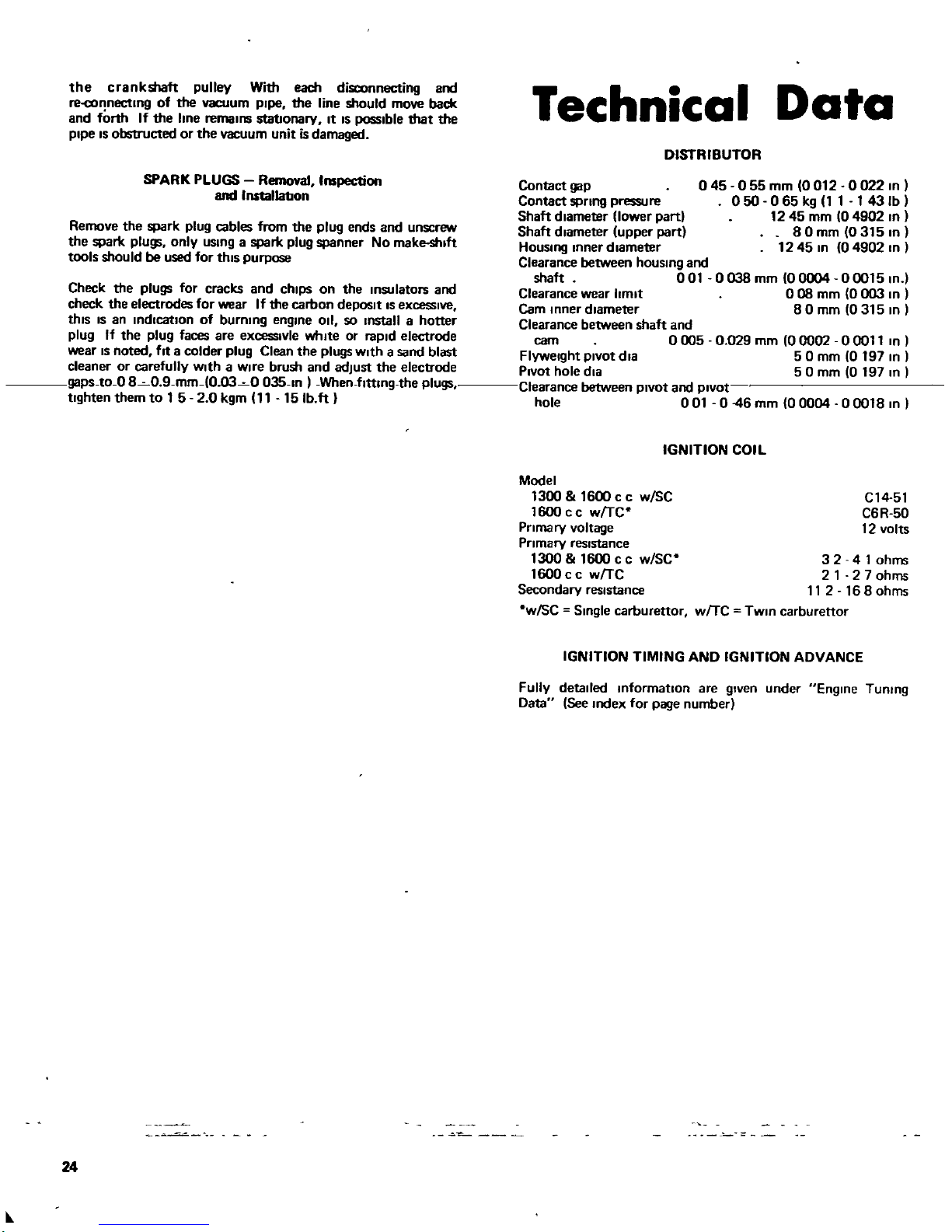
the
crank
pulley
With
each
disconnecting
and
re
connectlOg
of
the
vacuum
pIpe
the
line
should
move
back
and
forth
If
the
line
remalOs
stationary
It
IS
possible
that the
pipe
IS
obstructed
or
the
vacuum
unit
is
damaged
SPARK
PLUGS
Removal
Inspection
and
Installation
Remove
the
spark
plug
cables
from the
plug
ends and
unscrew
the
spark
plugs
only
uSlOg
a
spark
plug
spanner
No
make
sluft
tools
should
be
used
for
thIS
purpose
Check
the
plugs
for
cracks
and
chips
on
the
IOsulators
and
check
the
electrodes
for
wear
If
the
carbon
depOSIt
IS
excessive
thIS
IS
an
Indication
of
bummg
englOe
Oil
so
Installahotter
plug
If
the
plug
faces
are
excesslvle
whIte
or
rapid
electrode
wear
IS
noted
fitacolder
plug
Clean
the
plugs
Withasand
blast
cleaner
or
carefully
WIth
a
Wire
brush
and
adjust
the
electrode
gapS
to
O80
9
mm
0
030035
ln
When
flttmg
the
plugs
tighten
them
to
1
5 2
0
kgm
11
15Ibft
24
II
Technical
Data
DISTRIBUTOR
045
055
mm
0012
002210
050 065
kg
1 1 143Ib
1245
mm
0490210
80mm
03151O
1245
In
0490210
Contact
gap
Contact
spring
pressu
re
Shaft
diameter
lowerpart
Shaft
diameter
upper
part
HouslOg
lOner
diameter
Clearance
between
housmg
and
shaft
001
0038
mm
00004
0001510
Clearance
wear
limit
0
08
mm
0
003
10
Cam
lOner
diameter
80
mm
0315
10
Clearance
between
shaft
and
cam
0
005
Flyweight
piVOt
dla
PIVot
hole
dla
Clearance
between
pIVOt
and
piVOt
hole
001
046
mm
00004 00018
10
0
029
mm
00002
00011
In
50
mm
0197
In
50
mm
0
197
10
IGNITION
COIL
Model
1300 1600
c
c
wlSC
1600
c c
wrrc
Primary
voltage
Primary
resistance
1300 1600
c c
w
SC
1600
c c
wrrc
Secondary
resistance
wlSC
SlOgle
carburettor
C14
51
C6R
50
12
volts
3 2 41ohms
212 7
ohms
112168
ohms
wrrc
TwlO
carburettor
IGNITION
TIMING
AND
IGNITION
ADVANCE
Fully
detailed
IOformatlon
are
gIven
under
EnglOe
TUOlng
Data
See
Index
for
page
number
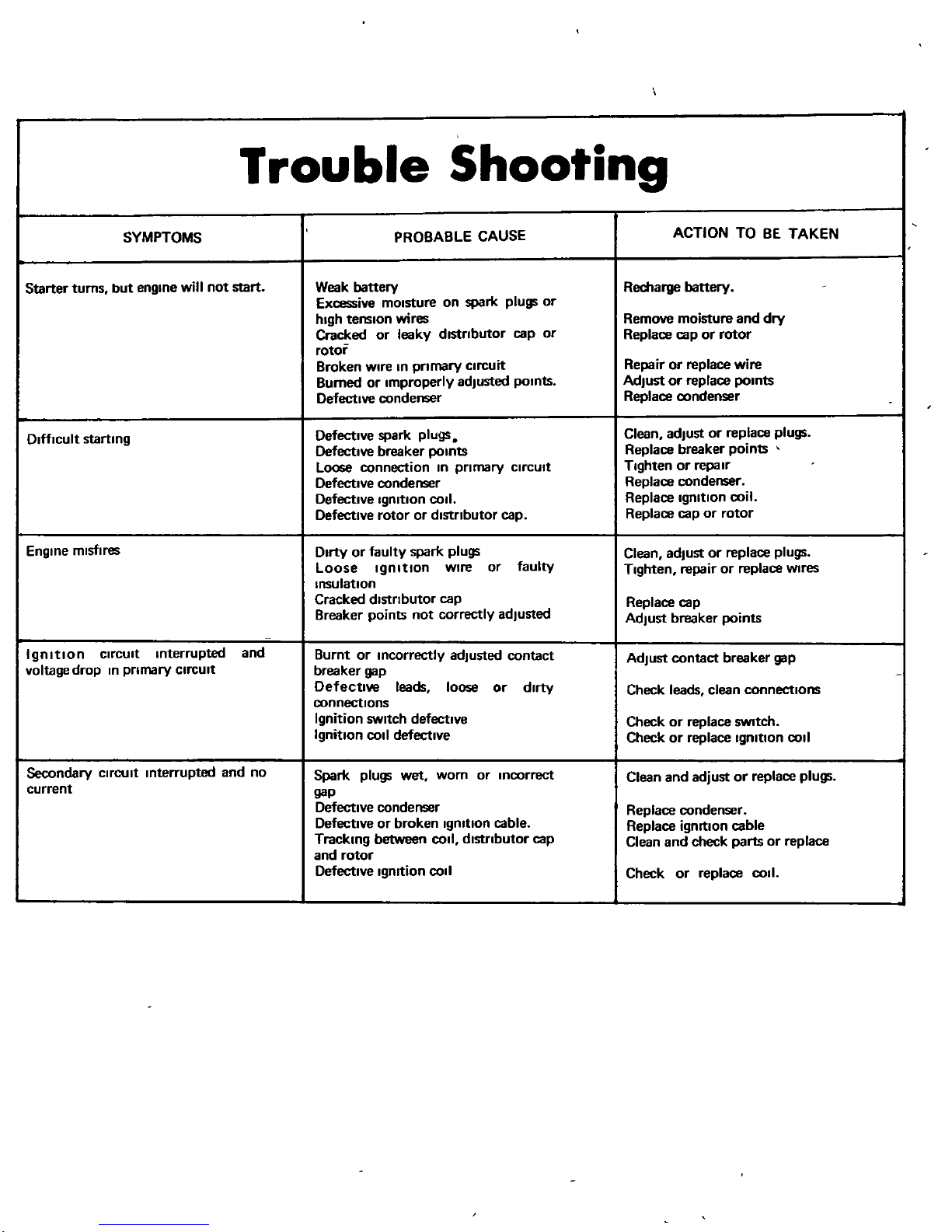
Trouble
Shooting
SYMPTOMS
PROBABLE
CAUSE
ACTION
TO
BE
TAKEN
Starter
turns
but
engine
will
not
start
Weak
battery
Recharge
battery
Excessive
mOisture
on
spark plugs
or
high
tension
wires
Remove
moisture
and
dry
Cracked
or
leaky
dlStnbutor
cap
or
Replace
cap
or
rotor
rotor
Broken
wire
In
pnmary
CircUit
Repairorreplace
wire
Burned
or
Improperly
adjusted
points
Adjustorreplace
points
Defective
condenser
Replace
condenser
Difficult
starting
Defective
spark
plugs
Clean
adjUstorreplace
plugs
Defective
breaker
points
Replace
breaker
points
Loose
connection
In
pnmary
CircUit
Tighten
or
repair
Defective
condenser
Replace
condenser
Defective
Ignition
COil
Replace
Ignition
coil
Defective
rotor
or
dlstnbutor
cap
Replace
cap
or
rotor
Engine
misfires
Dirty
or
faulty
spark
plugs
Clean
adjUst
or
replace
plugs
Loose
Ignition
wire
or
faulty
Tighten
repair
or
replace
Wires
Insulation
Cracked
dlstnbutor
cap
Replace
cap
Breaker
points
not
correctly
adjusted
AdjUst
breaker
points
Ignition
CirCUit
Interrupted
and
Burnt
or
Incorrectly
adjusted
contact
AdjUst
contact
breaker
gap
voltage
drop
In
pnmary
CircUit
breaker
gap
Defective
leads
loose
or
dirty
Check leads clean
connections
connections
Ignition
SWitch
defective
Check
or
replace
SWItch
Ignition
COil
defective
Check
or
replace
IgnitIOn
COil
Secondary
circuit
Interrupted
and
no
Spark
plugs
wet
worn
or
inCOrrect
Clean and
adjustorreplace
plugs
current
gap
Defective
condenser
Replace
condenser
Defective
or
broken
Ignition
cable
Replace
ignition
cable
Tracking
between
COil
distributor
cap
Clean and
check
parts
or
replace
and
rotor
Defective
Ignition
COil
Check
or
replace
COIl
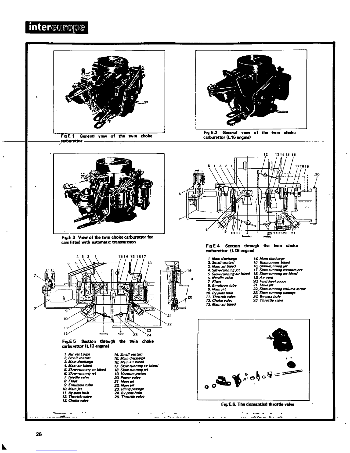
interceM
j
@
p
ce
L
ill
il
0
7
i
l
f
I
IJ
f
A
a
r
o
Fill
E1General
of
the
twin
choke
Cllburettor
FJg
E3V
of
the
tWin
choke
cartJurettor
for
cars
fitted
With
ilJtomatlC
transnllSSlOft
6
7
FIlI
E5SectIOll
through
the
c
arburetlllr
L
13
1
1
A
rWllltptplt
2
Small
venturI
1MlJmd
MmlTbJeed
5
Slow
tunnlllf
a
bleed
6 SIow
runnm6
f1t
7
8
F
9
Emulston
rubll
14
M
m
jet
8y
ho
12
Throm
13
ChoIc
SmsJIWNlbm
5
MatndlS
C
6
Mam
air
bleed
7
SlorH1lnnmg
II
bleed
IS
SIow
runnlnfl
fIl
19
Vacuum
prsfon
20
Power
aIw
21
Ifam
et
22
Maml
23
ldl
l
24
8
hole
25
Throttle
W
26
J
T
t
1
4
f
c
Fog
E2General
of
the
twm
choke
cartJuret1D
L
16
englnel
12
1314
IS
16
FIg
E4SectIon
through
the
twin
choke
carburetlllr
L
16
englnel
MIl
dach
2
Small
venturi
3
MamllJrble
J
4
Slof
IHUnmng
Jet
5
Slow
runnmg
lII
bleed
G
N
tI
aM
7
FI
8
Emublon
tubtJ
9
M
lnJflf
10
s
110
77
Throttle
aIwl
12
C
rok
aw
13
MII
bltJed
t
c
Mamd
SiChatfpl
15
Econor
zer
bleed
16
SIow
runmng
Jet
17 SJoVN
unnmg
econonuzs
18
Slow
running
BIf
bIet1d
19
AN
vent
2Q
Fue
let1el
g
JiUgt
21
Mam
Jet
22
SJow
runnmg
KJlumtllCl
flW
2
SIoMNllnmng
24
8
11010
25
Throttle
aWe
obo
00
FIQEThe
dlStll8nt1ed
throttle
vaJve
Fuel
System
DESCRIPTION
The
fuel
system
consists
basically
of
fuel
tank
fuel
pump
fuel
strainer
air
cleaner
and
carburettor
The
Datsun
1300ISfitted
with
a
two
barrel
carbu
rettor
whereas
the
Datsun1600
has
either
a
two
barrel
downdraught
carburettor
or
twin
SU
type
carburettors
CARBURETTOR
Single
tWin
choke
Removal
The
single
carburettor
versions
are
fitted
to
the
Datsun
1300
Type
designation
DCK306
and
the
Datsun
1600
Type
deSignation
OAF
328
See
Fig
E
2
E
3
To
remove
the
carburettor
take
off
the
air
cleaner disconnect
the
fuel
pipe
and
the
vacuum
pipe
from the
carburettor
end and
detach
the
choke
cable
Remove
the
throttle
linkage
and
undo
the
four
nuts
and
washers
securing
the
carburettor
to
the manifold
Lift
off
the
carburettor
CARBURETTOR
Dismantling
The
main
Jets
slow
runnlhg
Jets
and
the
needle
valves
for
the
pnmary
and
secondary
stage
are
accessible
from the
outside
of
the
carburettor
body
Remove
the
Jets
and
needles
Fig
E
4
E
5
The
upper
body
can
be
removed
by
removing
the choke
connecting
rod
pp
connecting
rod
return
spring
stop
pin
and
the
four
secunng
screws
Figs
E6E 7
andE8
Mam
body
Remove
the
pnmary
and
secondary
emulSion
tubes
by
removing
the
main air
bleeds
Fig
E
10
Remove
the
cylinder
cover
and
take
out
the
accelerator
pump
F
Ig
E
11
Separate
the
float
chamber
from the
throttle
butterfly
block
by
removing
the
rod
linking
the
diaphragm
to
the
secondary
throttle
valve
and
the
four
securing
screws
Fig
E
12
Remove
the
float
chamber
cover
and
the
float
Fig
E
13
Dismantle
the
diaphragm
by
removing
three
screws
holding
the
diaphragm
chamber
and
then
removing
three
screws
holding
the
diaphragm
chamber
cover
Fig
E
14
The
fuel
return
system
shown
In
Fig
E
15
should
not
be
dismantled
If
not
abolutely
necessary
When
dismantling
take
care
not
to
damage
the
bimetal
spring
Dash
pot
damper
This
mechanISm
IS
fltteto
thecarburettor
Fig
E
16onvehicles
With
automatic
transmission
and
IS
linked
to
the
pnmary
throttle
vale
linkage
CARBURETTOR
Inspection
Thoroughly
clean
all
parts
Inasu
Itable solvent
and
blowout
all
Jets
and
passages
With
compressed
air
Check
all
parts
for
wear
and
damage
With
special
attention
to
the
follOWing
parts
Check
the
float
needle
and
the
seat
for
wear
If
worn
replace
the
assembly
Check
the
throttle
and
choke
valve
shafts
and
bores
for
eccentriCity
Check
the
slow
running
Jet
needles
for
burrs
and
ndges
Replace
parts
as
necessary
Check
choke
tube
clusters
for
wear
or
slackness
and
If
necesssary
replace
the
cluster
Check
all
linkages
for
excessive
wear
and
the
filter
screen
for
blockage
and
distortion
Check
the
operation
of
the
accelerator
pump
and
the
diaphragm
chamber
for
damage
to
the
diaphragm
and
air
leaks
Repair
or
replace
any
defective
components
CARBURETTOR
Assembly
The
assembly
IS
carned
outIn
reverse
order
to
the
dismantling
procedure
Special
care
should
be
taken that
no
defective
brittle
or
hard
gaskets
are
used
Where
these
are
found
they
should
be
replaced
When
connecting
the
linkages
be
careful
not
to
bendordeform
any
of
the
components
CARBURETTOR
Adjustments
Float
level
If
the
fuel
level
IS
at the
gauge
line
the
float
IS
correctly
set If
thiS
IS
not
the
case
hold
the
float
level
In
ItS
chamber
and
check
that the
gap
between
the
float
seat
and
the
stem
of
the
float
needle
valveISabout10
mm
0039
In
for
the
L13
and15
mm
059
In
for
the
L16
engine
Fig
E
17
Bend
the
float
seat
as
shown
In
Fig
E
18
Interlock
startJng
system
With
the
choke
valve
fu
lIy
closed
there
should
be
a
clearance
of
1
3
mm
00512
In
between
the
pnmary
throttle
valve
and
the
carburettor
body
In
the
ase
of
the
OAF
328
carburettor
and
a
clearance
of 072
mm
0028
In In
the
case
of
the
DCK
306
carburettor
Fig
E19and
Fig
E
20
Interlock
opemng
of
prunary
and
secondary
throttle
valves
When
the
pnmary
throttle
valve
IS
opened
to
the
speCified
degree
590
for
OAF
328
or
560
for
DCK
306
there
should
be
a
clearance
of
9 10
mm
03583
In In
case
of
the
OAF
328
carburettor
or
6
40
mm
0
252
In
between
the
throttle
valve
and
the
Inner
wall
of
the
throttle
chamber
See
also
Figs
E
22
and
Fig
E
23
To
adjUst
the
clearance
bend
the
pOint
marked
A
on
the
adjustment
plate
Slow
roORing
adjustment
The
slow
running
adjustment
IS
obtained
by
adjusting
the
throttle
valve
stop
screw
and
the
slow
running
volume
control
screw
Screw
In
the
slow
runnlng
volume
control
screw
and
back
off
by approximately
three
turns
Then
screw
In
the
throttle
stop
screw
and
start
the
engine
Unscrew
the
throttle
stop
screw
until
the
engine
beginS
to
rotate
unevenly
when
the
englfle
speed
Will
gradually
drop
Now
screw
In
the
slow
running
volume
control
screw
until
the
engine
runs
smoothly
at
the
D
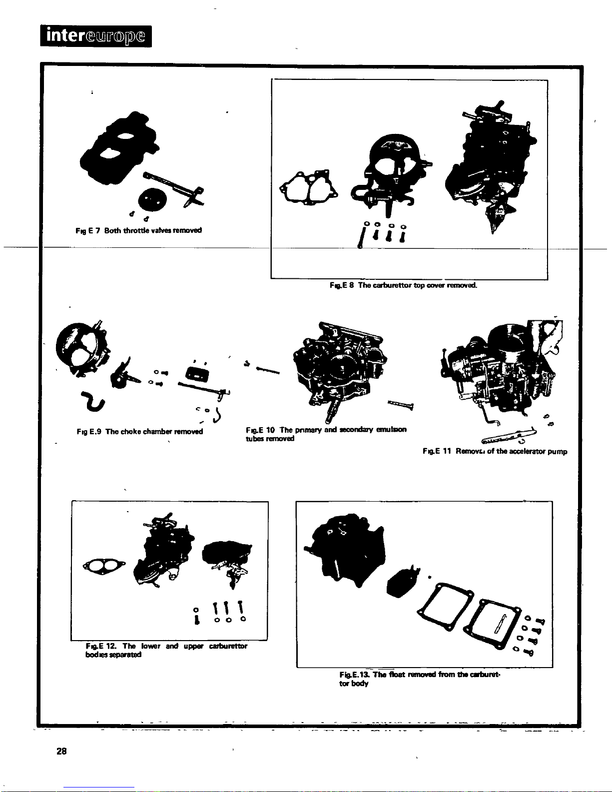
inter
D
i
@
j1
4
4
alh
throttle
valves
relllDved
FIlIE
7
B
removed
carburettor
top
caver
FIlI
E B
The
O
l
1
Jo
u
0
ll
li
il
4
I
f
It
F
I
0
D
j
hamber
relllDvecI
9
The
choke
c
Fill
E
ndary
emu
end
lOCO
10
The
pnmary
FIlI
E
ell
tubes
remov
q
o
i
0 0 0
carburetlDr
The
lower
and
upper
FIlI
E
12
bod
separa18d
ret
from
the
reIIICJII8II
FIg
E
13
The
float
tor
body
28
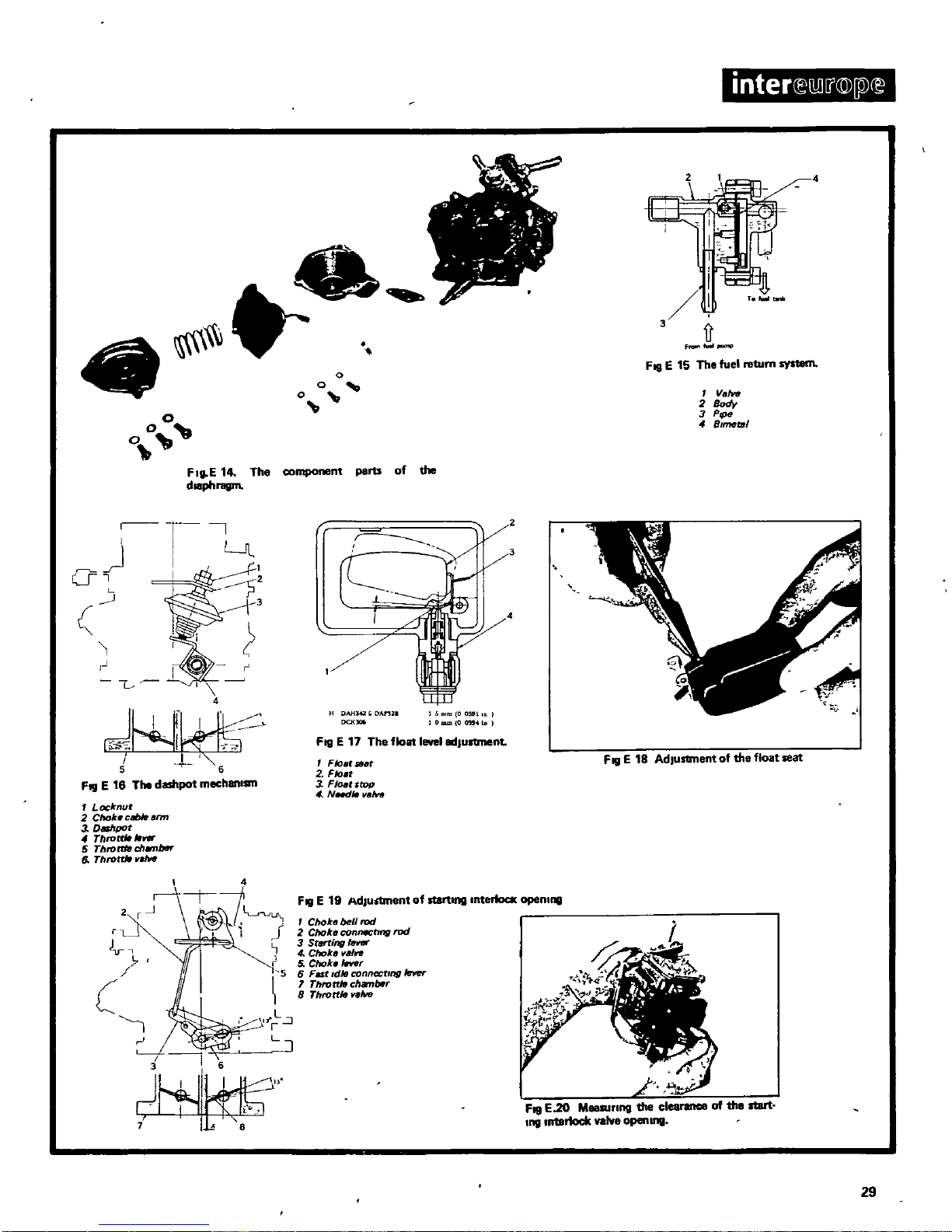
4
o
o
0
ImmIIII
3
1J
F
fuoIlpul
flp
FIQ
E
15
The fuel
return
sys1em
Valve
2
Body
3
PIPe
if
SImtlttJl
FgE
14
The
component
parts
of
the
dl8phragm
r
r
a
i
L
J
I
Ll1
1
f
i
r
L
4
5 6
FI
I
E
16
The
dashpot
mechBlllsm
7
Locknut
2
Chok
cl
Jblearm
3
OGhpot
ThlO
0
5
Throttle ch
btK
6
Throm
l
aIw
2
r
rL
i
r
L
fr
J
L
J
JhaJi
DAH42AnZl
OCK
00
1
I
OmmDau
I
Fill
E17The
flollllevel
adJullment
Float
SlHt
2
FIo
t
3
FINt
ltop
4 NeJIII
van
FIQE18
Adlusanent
of
the
float
18111
FI
I
E
19
AdJuotment
of
slllI
tlng
Interloca
opemng
Choke
bell
rod
2
Choke
connctlllfl
rod
3
S11Irtlng
Ie
4
Choke
vain
5
Choke
ItNer
6
Fat
dIB
connectIng
IeYer
1
Throttle
chamber
8
Throttle
valw
FIQE20
MeaRltlng
the
clearance
of
the
start
ng
Interlock
valve
Opel1l11l1
29
highest
speed
Re
adjust
the
throttle
stop
screw
to
reduce
the
engine speed
Repeat
thiS
adjustment
until
an
engine
speed
of
550
rpm
has
been
obtained
Care
should
be
taken
not
to
screw
In
the
slow
running
volume
control
screw
to
tightly
as
otherwise
the
tip
of
the
screw
mightbedamaged
Dashpot
adjustment
ThiS
adjustmentISonly
necessary
on
the
Datsum
1600
fitted
With
automatic
transmission
With the
engine
at
operating
temperature
check
that
the
throttle
lever
Will
touch the
dashpot
stem
when
the
engineISrunning
With
1800
2000
rpm
There
should
be
no
load
on
the
engine
Fig
E
161
If
thiS
IS
not
the
case
slacken
the
dash
pot
locknuts
and
turn
the
dash
pot
to
the
nght
or
left
until
the
throttle
lever touches
the
dash
pot
stem
at
the
specified
engine
speed
In
thiS
condition the
clearance
between
the
throttle
valve
and
the
throttle
chamber
wall
should
be
08
mm
0071
In
I
corresponding
to
a
throttle
valve
angle
of
lO
SU
TYPE TWIN
CARBURETTORS
Dismantling
Unscrew
the
plug
and
Withdraw
the
piston
damper
Take
out
the
two
suction
chamber
secunng
screws
11ft
off
the
suction
chamber
and
Withdraw
the
piston
and
Jet
needle
Disconnect
the
rod from the
bottom
of
the
Jet
and
the
nylon
feed
tube
from the
base
of
the
float
chamber
Unscrew
the
Jet
adjusting
nut
and
the
spnng
Unscrew
the
Jet
beanng
locking
nut
Remove
the
float
chamber
cover
secunng
bolts
and
Withdraw
the
float
Screw
out
the
needle
valve
assembly
The
dismantling
stages
are
shown
In
Figs
E24E25andE26
CARBURETTOR
InspectIon
Note the condition
of
the
needle
valve
and
the
seating
Fit
a
new
needle
valve
and
seating
If
necessary
If
the
Jet
needle
IS
bent
or
otherwise
damaged
Withdraw
the
locking
screw
In
the
piston
and
fit
a
new
needle
Push
the
needle
In
until
the
shoulder
IS
flush
With
the
lower
face
of
the
piston
Fig
A
271
Clean
and
dry
the
piston
assembly
Lubncate the
piston
rod
WIth
thin
011
CARBURETTOR
Assembly
Reverse
the
dlamantllng
procedure
and
centre
the
Jet
Centnng
the
Jet
Screw
the
Jet
adjusting
nut
up
as
far
as
poSSible
11ft
the
piston
With
the
lifting
pin
and
allow
It
to
drop
It
should
drop
freely
onto
the
bndge
With
a
soft
metallic
click
Repeat
wltn
the
adjusting
nut
screwed
fully
down
If
the
piston
does
not
fall
freely
In
either
of
the
tests
proceed
as
follows
Disconnect
the rod from the
bottom
of
the
Jet
and
the
feed
tube
from the
base
of
the
float
chamber
Pull
out
the
Jet
and
the
tube
Unscrew
and
remove
the
Jet
adjusting
nut
and
the
spnng
Refit the
adjusting
nut
Without the
spnng
and
screw
It
up
as
far
as
pOSSible
Slacken
the
Jet
bearing
lock
nut
until
the
beanng
can
be
turned
With
the
fingers
Remove
the
piston
damper
and
press
the
piston
down
onto
the
bndge
Tighten
the
lock
nut
tift
lhe
pjS
on
and
nQ
1l
whetlliij
IS
falls
freely
fully
19w
ir
the
30
adjusting
nut
and
check
again
If
the
second
check
produces
a
sharper
click than
the
first
repeat
the
centnng
Refit the
parts
that
have
been
removed
pour
thin
011
Into
the
hollow
rod
of
the
piston
damper
to
Within05
In
12
7
mml
of
the
top
of
the
rod
CARBURETTOR
Adjustments
The
proper
adjustment
of
the
two
carburettors
IS
extremely
Important
In
obtaining
peak
vehicle
performance
and
redUCing
fuel
consumption
Carburettor
synchromzsnon
and
idhng
adjustment
Remove
the
air
cleaner when
the
engine
has reached ItS
operating temperature
and
slacken
the
throttle
adjusting
screws
The
headsofthe
adjusting
screws
must
not
contact
the
throttle
lever
Also
make
sure
that
the
front
and
rear
throttle
shafts
are
not
connected
Tighten
the
Idling
adjusting
nuts
of
the
front
and
rear
carburettor
by
one
turn
towards
the
top
of
the
carburettors
and
gradually
back
them
off
After
the
nuts
have
been
turned
approximately
half
a
turn
the
nuts
Will
contact
the
needle
heads
Back
off
the
nuts
from
thiS
pOSition
by
approx
one
andahalf
turn
Make
sure
that the
Idling
adjusting
nuts
of
both
carburettors
are
In
the
same
pOSition
The
dimenSion
A
adjustment
descnbed
later
between
the
Jet
bndge
and
the
needle
head
should
then
be
approx
1
5
mm
0591
In
I
Screw
In
the
throttle
adjustment
screws
of
the
front
and
rear
carburettors
and
start
the
engine
The
engine
should
retain
Its
operation
temperature
before
carrying
out
the
next
step
Now
turn
the
throttle
adjusting
screw
of
both
carburettors
to
reduce
the
engine
speed
to
approx
600 700
rpm
The
engine
should
turn
over
smoothly
and
consistent
Ifaflow
meter
IS
available
apply
the
Instrument
to
the
front
carburettor
flange
and
turn
the
adjustment
screw
on
the
flow
meter so
that the
upper
end
of
the
float
In
the
glass
tube
IS
In
line
With
the
scale
Llft
off
the
flow
meter
and
re
apply
It
to
the
rear
carburettor
Without
altering
the
setting
of
the
flow
meter
adjusting
screw
If
the
pOSItion
of
the
float
IS
not In
line
With
the
scale
adjUst
the
rear
carburettor
throttle
adjusting
screw
to
align
the
float
With
the
mark
on
the
scale
With
the
carburettor
flow
correctly
adjusted
tighten
the
Idling
adjusting
nuts
of
both
carburettors
by
approx
18of
a
turn
and
stop
the
adjusting
of
the
nuts
at a
pOint
where
the
engine
speed
IS
fastest
and
smoothest
Without
missing
or
hunting
If
thiS
point
cannot
be
detenmned
bnng
the
nuts
back
to
their
onglnal
positions
and
unscrew
them
from
thiS
pOSition
until
the
engine
runs
fastest
und
smoothest
Then
slacken
the
throttle
adjusting
screws of
the
front
and
rear
carburettors
and
adjUst
the
engine
speed
to
the
specified
value
of
650
rpm
for
standard
engines
or
700
rpm
for
models
With
011
cooler
Make
sure
that the
air
flow
of
both
the
carburettors
remains
unchanged
Screw
In
the
throttle
adjusting
screws
until
their
heads
contact
the
throttle
connecting
lever
Connect
up
the
front
and
rear
throttle
shaft
Without
changing
the
Idling
speed
setting
Move
the
throttle
interconnecting
shaft
and
accelerate
the
engine
a
few
times
When
the
engine
IS
settled
once
more
In
Its
Idling
speed
check
that the
speedISunchanged
Re
check
also
the
connection
of
the
interconnecting
shaft
Then
turn
tha
Interconnecting
shaft
adjusting
screw
to
Increase
the
engine
speed
to
800
1000
rpm
Check
y
means
of
the
flow
meter
Jf
the
Idling
air
flOW
IS
the
same
tor
both
carburettors
If
necessary
 Loading...