

Datsun 510 series, 610 series, 1300, 1400, Bluebird 160 B Workshop Manual
...
i
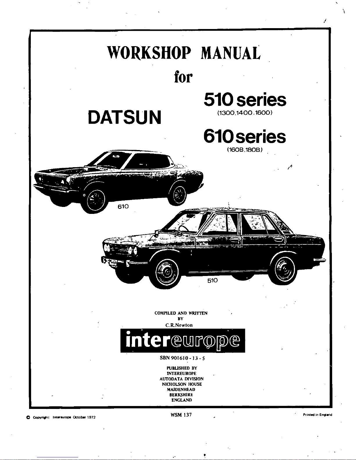
WORKSHOP
MANUAL
for
510
series
DATSUN
130014001600
610
series
I
l
A
160B
180B
COMPILED
AND
WRlTTEN
av
CRNewton
SBN
901610
13
5
PUBUSHED
BY
OOEREUROPE
AUTODA
TA
DIVISION
NICHOLSON
HOUSE
MAIDENHEAD
BERKSHIRE
ENGLAND
C
Copyrirt
lnt
eurupe
Cktoblr
1972
WSM
137
Printed
Engl
w
i
I
inter
llil
j
@
W
E
Hu
tol
and
Type
Identl
ficatlOn
YOUR
MANUFACTURER
The
Nissan
Motor
Company
was
founded
in
1933
under
the
name
of
Jidosha
Seizo
Co
Ltd
In
1934
the present
title
was
adopted
and
during
1966
the
company
merged
with
Prin
c
Motors builders
of
the
Skyline
and
Gloria
ars
With
the
head
office
and
six
main
factories
near
Tokyo
Japan
other
sister
plants
ace
also
in
production
in
various
countries
throughout
the
world
YOUR
VEHICLE
In
the
early
days
of
the
company
s
history
vehicles
constructed
were
given
the
trade
name
DA
TSDN
which
means
SONofDAT
the
initials
of
three
of
the
financial
backers
forming
the
syllable
DATTo
avoid
confusion
with a
similar
Japanese
word
the
name
was
eventually
changed
to
DATSUN
The
various
models
coveredinthis
Manual
together
with
alternative
namt
s
used
for
the
world
markets
are
listed
below
MODELS
COVERED
MODEL
ALTERNATIVE
IDENT
510
SERIES
Datsun
1300
510
SERIES
Datsun
1400
510
SERIES
Datsun
1600
610
SERIES
Bluebird
160
B
610
SERIES
Bluebird
180
B
00
SERIES
DATSUN
ISoo
ENGINE
FITTED
1300
c c
L
l3
1400
c
LI4
1600
c
c
LI6
1600
c
LI6
1800
c c
L
18
181S
GIS
WUUUU
I
fl
I
lfI
r
7
I
i
I
1
11
lii
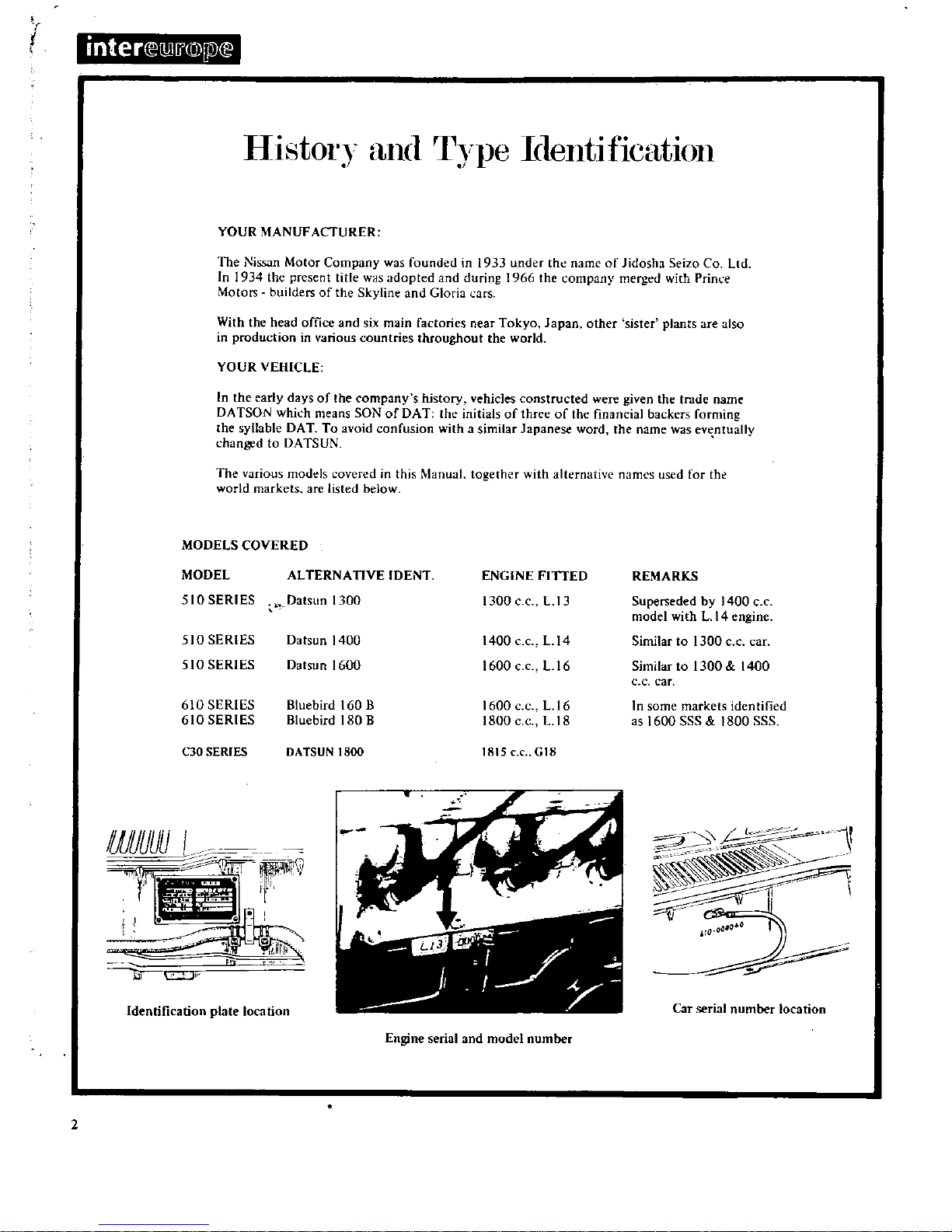
Identification
plate
location
Engine
serial
and
model
number
2
REMARKS
Superseded
by
1400
c
c
model
withL14
engine
Similar
to
1300
c c
car
Similar
to
1300 1400
e c
car
In
some
markets
identified
as
1600
SSS
1800
SSS
J
S
1
HI
I
Car
serial
number
location
inteN
j
@IP
B
Index
ENGINE
COOLING
SYSTE
l
IGNITION
SYSTE
I
FUEL
SYSTBl
CLUTCH
GEARUOX
PROPELLER
SHAFT
Id
DIFFERENTIAL
REAR
AXLE
nd
REAR
SUSPENSION
FRONT
SUSPENSION
STEERING
BRAKING
SYSTEM
ELECTRICAL
EQUIP
JENT
WIRING
JAGRA
IS
TROUBLE
SHOOTING
TIGHTENING
TORQUES
SERIES C30MODEL
SUPPLEMENT
AUTOSERVlCE
DATA
CHART
PART
NA
ESndALTERNATIVES
CONVERSION
TABLES
S
15
2S
33
43
51
62
7S
83
91
9S
lOB
liB
I2S
129
51
End
of
manuir
IntroductIon
OUf
intention
in
writing
this
Manual
is
to
provide
the
reader
with
all
the
data
and
in
formation
required
to
maintain
and
repair
the
vehicle
However
it
must
be
realised
that
special
equipment
and
skills
arc
required
in
some
caseS
to
carry
out
the
work
detailed
in
the
text
andwedo
not
recommend
that
such
work
be
attempted
unless
the
reader
possesses
the
necessary
skill
and
equipment
It
would
be
bettertohave
an
AUTHQRISED
DEALER
to
carry
out
the
work
using
the
special
tools
and
equipment
available
to
his
trained
staff
He
will
alsobein
possession
of
the
genuine
spare
parts
which
may
be
needed
for
replacement
The
information
in
the
Manual
has
been
checked
against
that
provided
by
the
vehicle
manufacturer
and
any
peculiarities
have
been
mentioned
if
they
depart
rom
usual
work
shop
practice
A
fault
finding
and
trouble
shooting
chart
has
been
insertedatthe
endofthe
Manual
to
enable
the
reader
to
pin
point
faults
and
so save
time
As
it
is
impossible
to
include
every
malfunction
only
the
more
usual
ones
have
been
included
A
composite
conversion
table
has
also
been
included
at
the
end
of
the
manual
and
we
would
recommend
that
wherever
possible
for
greater
accuracy
the
metric
system
units
are
used
Brevity
and
simplicity
have
been
our
aim
in
compiling
this
Manual
relying
on
the
number
ous
illustrations
and clear
text
to inform
and
instruct
the
reader
At
the
request
of
the
many
users
of
our
Manuals
we
have
slanted
the
book
towards
repair
and
overhaul
rather
than
maintenance
Although
every
care
has
been
taken
to
ensure
that
the
information
and
data
are
correct
WE
CANNOT
ACCEPT
ANY
LIABILITY
FOR
INACCURACIES
OR
OMISSIONS
OR
FOR
DAMAGE
OR
MALFUNCTIONS
ARISING
FROM
THE USE
OF
THIS
BOOK
NO
MATTER
HOW
CAUSED
I
3
t
r
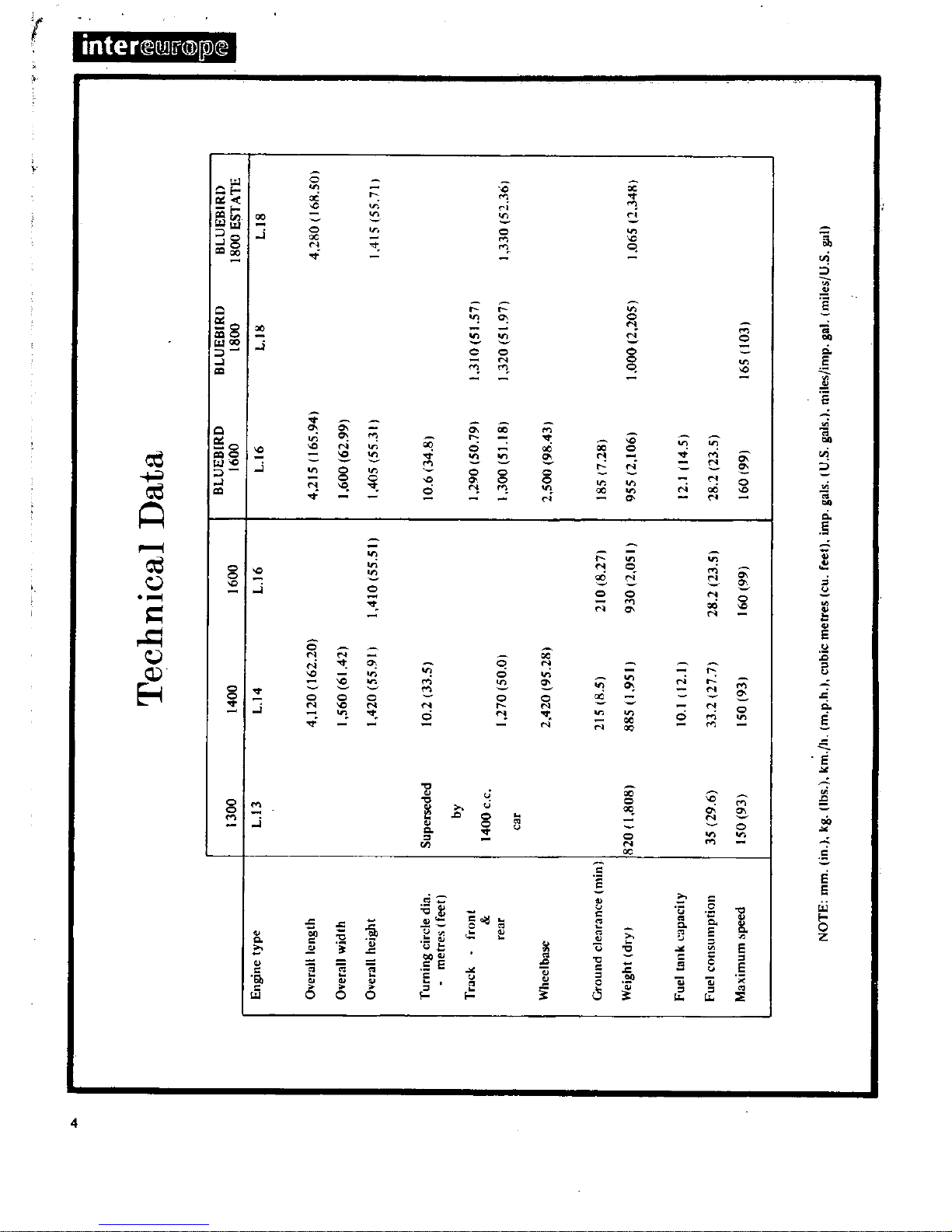
Engine
type
Ovendi
cngth
1300
L
13
Overall
width
Oyerall
height
Turning
circle
din
metres
tfeet
Supen
eded
by
Track
font
rear
1400
c
c
car
Ground
dearance
Olin
Weight
dry
I
820
808
I
Fuel
tClflk
capacity
35
29
6
150
93
Fuel
consumption
aximum
peed
Technical
Data
BLUEBIRD
400
1600
1600
U4
U6
0
4
120
162
20
1
560
6142
410
55
51
420
55
91
10
2
33
5
270
50
0
2
420
95
281
215
8
5
885
1
950
210
8
27
930
2
050
10
1
12
33
2
27
7
50
931
28
2123
5
60
99
L
16
4
215
165
941
1
600
62
99
405
55
3
Ii
0
6
34
8
290
5079
1
300
51
18
2
500
9843
185
7
281
955
2
1061
12
14
5
28
2
23
5
60
991
BLUEBIRD
1800
L
18
3
0
5
57
320
5
971
000
2
2051
165103
BLUEBIRD
1800
ESTATE
U8
4
280
168
501
4
5
557
330
52
361
1
065
2
348
EngIne
INTRODUCTION
ENGINE
Removal
ENGINE
DismantUng
ENGINE
Inspection
and
Overhaul
VALVES
VALVE
GUIDES
VALVE
SEAT
INSERTS
CAMSHAFT
AND
CAMSHAFT
BEARINGS
Checking
CYliNDER
BLOCK
PtSTONS
AND
CONNECTING
RODS
INTRODUCTION
The 1400
1600
cc
and
1800
cc
engines
are
four
cylinder
in
line
units
with
a
single
overhead
camshaft
and
fully
balanced
five
bearing
crankshaft
The
valves
are
operated
through
rockers
which
are
directly
activated
by
the
earn
mechanism
The
crankshaft
is
a
special
steel
forging
with
the
centre
main
bearing
equipped
with
thrust
washerstotake
up
the
end
thrust
of
the
crankshaft The
special
aluminium
pistons
are
of
the
strut
construction
to
control
thermal
expansion
and
have
two
compression
rings
and
one
combined
oil
ring
The
gudgeon
pins
have
special
hollow
steel
shafts
and
are
a
fully
floating
fitin
the
pistons
and
a
press
fit
in
the
connecting
rods
The
aluminium
alloy
cylinder
head
contains
wedge
type
combustion
chambers
andisfitted
with
aluminium
bronze
valve
seats
for
the intake
valves
and
heat resistant
steel
valve
seats
for
the
exhaust
valves
The
cast
iron
camshaftisdriven
by
a
double
row
roller
chain
from
the
crankshaft
pulley
The
engine
is
pressure
lubricated
by
a
rotor
type
oil
pump
which
draws
oil
through
an
oil
strainer
into
the
pump
housing
and
then
forces
it
through
a
full
flow
oil
filter
into
the
main
oil
gallery
ENGINE Removal
Place
alignment
marksonthe
bonnet
and
hinges
remove
the
bonnet
from
the
vehicle
2
Drain
the
cooling
system
and
engine
and
transmission
lubricant
Remove
the
radiator
grille
3
Discon
ect
the
battery
cables
and
lift
out
the
battery
4
Detach
the
upper
and
lower
radiator
hoses
remove
the
radiator
mounting
bolts
and
lift
the
radiator
away
from
the
vehicle
The
torque
converter
c
jng
pipes
must
be
disconnected
from
the
radiator
on
vehicles
fitted
with
automatic
transmission
S
Remove
the
COOling
fan
and
pulley
disconnect
the
fuel
pipe
from
the
fuel
pump
and
the
heater
hoses
from
the
engine
attachments
6
Disconnect
the accelerator
control
linkage
and
the
choke
CRANKSHAFT
AND
MAIN
BEARINGS
CAMSHAFT
AND
SPROCKET
FLYWHEEL
ENGINE
Assembling
VALVE
CLEARANCES
Adjusting
ENGINE
LUBRICATION
SYSTEM
OIL
PUMP
OIL
FILTER
CHANGING
THE
ENGINE
OIL
cable
from
the
carburettor
7
Disconnect
the
wirings
from
the
starter
alternator
ignition
coil oil
pressure
switch
and
temperature
sender
unit
8
Remove
the
clutch
slave
cylinder
Fig
A
2
and
its
return
spring
9
Disconnect
the
speedometer
cable
and
withdraw
the
plug
connector
from
the
reversing
light
switch
10
Disconnect
the
shift rods
and
seJector
rods
and
remove
the
cross
shaft
assembly
as
described
in
the
section
Gear
box
II
Disconnect
the
front
exhaust
pipe
from
the
exhaust
manifold
disconnect
the
centre
pipe
from
the
rear
pipe
and
remove
the
front
pipe
pre
muffler
and
centre
pipe
assembly
12
Disconnect
the
propeUer
shaft
flange
from
the
companion
flange
from
the
gear
carrier
13
Jackupthe
gearbox
slightly
and
remove
the
rear
engine
mounting
bracket
bolts
remove
the
mounting
cross
member
and
handbrake
cable
c1amp
14
Remove
the
bolts
securing
the
front
engine
mounting
brackets
to
the
crossmember
15
Attach
lifting
cable
or
chainstothe
hooks
installed
at
the
front
and
rear
of
the
cylinder
head
Lower
the
jack
under
the
gearbox
and
carefully
lift
and
tilt
the
engine
and
gearbox
unit
Withdraw
the
engine
and
gearbox
from
the
compartment
making
sure
thatitis
guided
past
the
accessories
installed
on
the
body
ENGINE
Dismantling
Remove
the
engine
as
previously
described
and
carefully
clean
the
exterior
surfaces
Cbeck
for
signs
of
fuel
oil
or
water
leaks
past
the
cylinder
head
and
block
Remove
the
air
cleaner
alternator
distributor
and
starter
motor
Plug
the
carburettor
air
horn
and
distributor
hole
to
prevent
the
ingress
of
foreign
matter
Remove
the
gearbox
from
the
engine
drain
the
engine
oil
and
coolant
Mount
the
engine
in a
suitable
stand
the
special
engine
attachment
ST05260001
and
engine
ST0501SOO0
should
be
usedifavailable
Fig
A
3
5
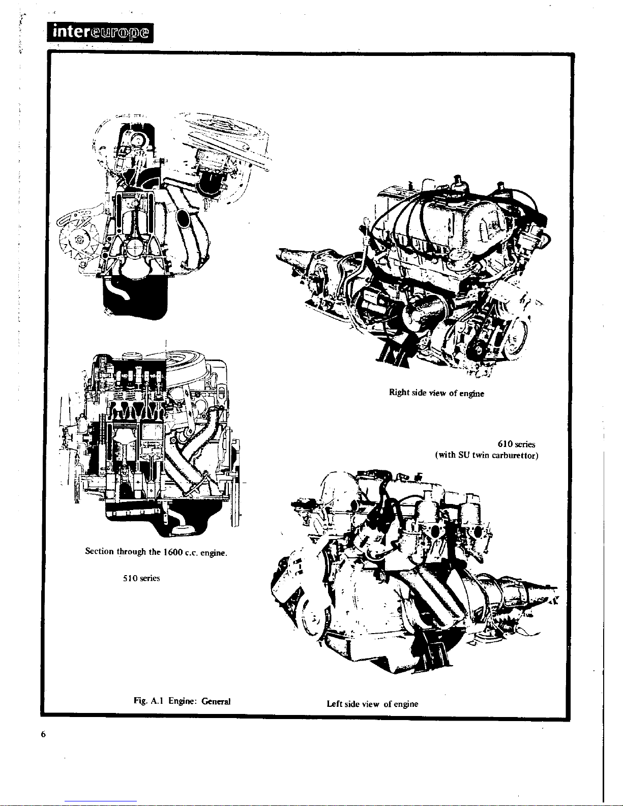
engine
600
tb
tllroogh
Section
S
O
sef1
es
ofenll
A
o
ne
l
Right
S
0
61
ttor
bure
n
car
l
tWI
thS
hi
4
t
V
ne
of
engJ
vie
lJ
lt
side
Gene
ol
Engine
FIS
to
fl
J
J
f
1
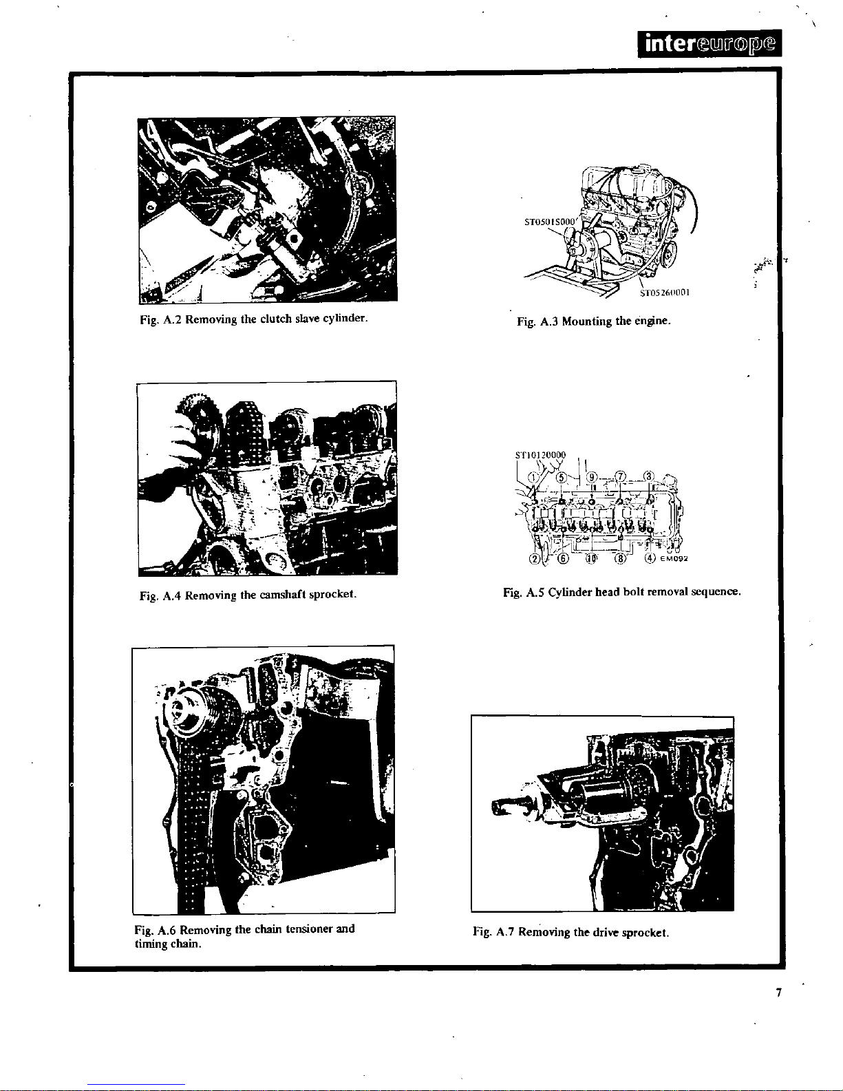
ST052fiOOOl
Fig
A
2
Removing
the
clutch
slave
cylinder
Fig
A
3
Mounting
the
engine
STI
0
120000
CI
@
j
91
7
m
I3L
I
T
IC
t
J
i1
C
J
6
i
11
j
1
j
4
I
U
O
J
I
Ll
LJJ
1r9i
V
@
1
EM092
Fig
AA
Removing
the
camshaft
sprocket
Fig
A
5
Cylinder
head
bolt
removal
sequence
t
J1
I
J
1
1
i
I
G
qt
7
r
J
O
I
IS
Fig
A
6
Removing
the
chain
tensioner
and
timing
chain
Fig
A
7
Removing
the
drive
sprocket
7
inter
lliJ
j
@I
IJ
I
7
4
i
ll
W
f
l
rr
er
j
il
Fig
A
9
Removing
the
flywheel
Fig
A
S
Removing
the
pistons
and
connecting
rods
Fig
A
II
Removing
the
baffle
plate
and
net
c
1
1i
t1
I
c2
r
Id
f
tij
Fig
A
IO
Removing
the
Tear
main
bearing
cap
Fig
A
12
Removing
the
piston
pin
Fig
A
13
Removing
the
valves
Fig
Al4
OIecking
the
cylinder
head
joinlface
Fig
AI5
Reaming
the
valve
guide
8
Remove
the
fan
and
pulley
the
right
hand
engine
mounting
and
oil
filter
Remove
the
oil
pressure
switch
Remove
the
following
items
oil level
gauge
spark
plugs
thermostat
housing
rocker
cover
carburettor
and
inlet
and
exhaust
manifolds
Remove
the
clutch
assembly
as
described
in
the
section
CLUTCH
Remove
the
left
hand
engine
mounting
crankshaft
pulley
water
pump
fuel
pump
fuel
pump
drive
earn
and
cam
shaft
sprocket
See
Fig
A
4
Remove
the
cylinder
head
bolts
in
the
sequence
shown
in
Fig
A
5
and
lift
off
the
cylinder
head
Invert
the
engine
and
remove
the
oil
sump
and
oil
strainer
oil
pump
and drive
spindle
assembly
front
cover
and
chain
tensioner
Remove
the
timing
chain
oil
thrower
crank
shaft
worm
gear
and
chain
drive
sprocket
See
Fig
A6andA
7
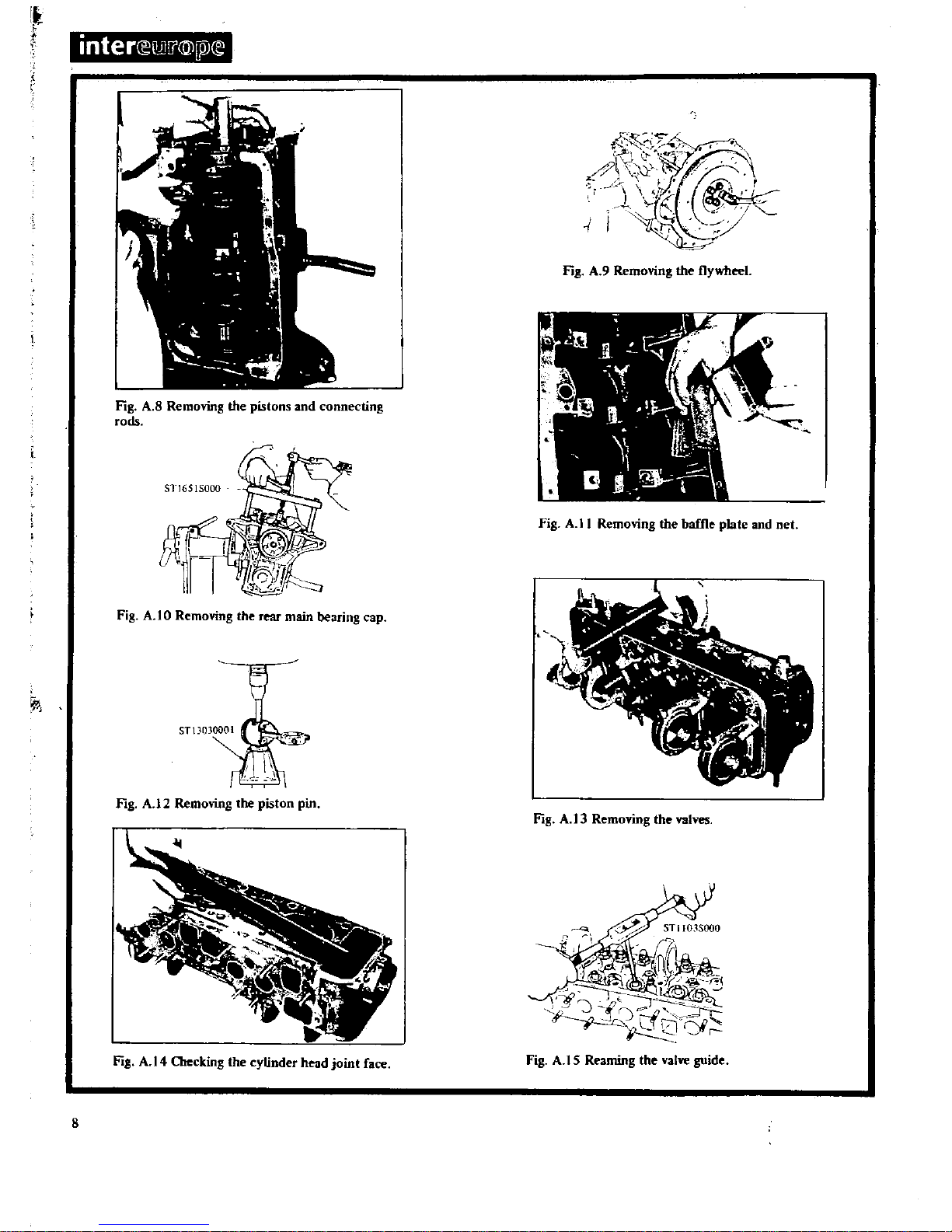
Remove
the
connecting
rod
caps
and
push
the
pistons
and
connecting
rods
through
the
top
of
the
boresasshown
in
Fig
A
B
Keep
the
connecting
rod
caps
with
their
respective
rods
to
ensure
that
they
are
assembled
in
their
original positions
Remove
the
flywheel
retaining
bolts
and
withdraw
the
fly
wheel
Fig
A
9
Remove
the
main
bearing
caps
using
the
special
puller
ST
1651
SOOO
to
withdraw
the
centre
and
rear
main
bearing
caps
as
shown
in
Fig
A
lORemove
the
rear
oil
seal
and
lift
out
the
crankshaft
remove
the
baffie
plate
and
cylinder
block
net
Fig
A
II
Remove
the
piston
rings
withasuitable
expander
and
press
out
the
gudgeon
pins
under
an
arbor
press
using
the
special
stand
STl300001
as
shown
in
Fig
A
12
Keep
the
dismantled
parts
in
ordersothat
they
can
be
reassembled
in
their
original
positions
Slacken
the
valve
rocker
pivot
lock
nut
and
remove
the
rocker
arms
by
pressing
down
the
valve
springs
Remove
the
camshaft
taking
carenot
to
damage
the
bearings
and
earn
lobes
Withdraw
the
valves
using
the
valve
lifter
STl2070000
as
shown
in
Fig
A
13
ENGINE
Inspection
and
Overhaul
Cylinder
Head
and
Valves
Clean
all
parts
thoroughly
and
remove
carbon
deposits
with
a
blunt
scraper
Remove
any
rust
which
has
accumulated
in
the
water
passages
and
blow
through
the
oil
holes
with
compres
sed
airtomake
sure
that
they
are
clear
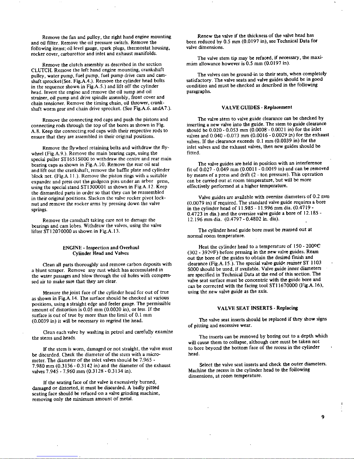
Measure
the
joint
faceofthe
cylinder
head
for
outoftrue
as
shown
in
Fig
A
14
The
surface
should
be
checked
at
various
positions
using
a
straight
edge
and
feeler
gauge
The
permissible
amount
of
distortion
is
0 05
mm
0
0020
in
or
lessIfthe
surface
is
outoftrue
by
more
than
the
limit
of01
mm
0
0039
in
it
will
be
necessary
to
regrind
the
head
Clean
each
valve
by
washing
in
petrol
and
carefully
examine
the
stems
and
heads
If
the
stem
is
worn
damaged
or
not
straight
the
valve
must
be
discarded
Check
the
diameter
of
the
stem with
a micro
meter
The
diameter
of
the
inlet
valves
should
be7965
7
980
mm
0
313603142
in
and
the
diameter
of
the
exhaust
valves7945
7
960
mm
0
312803134
in
If
the
seating
faceofthe
valve
is
excessively
burned
damaged
or
distorted
it
must
be
discarded
A
badly
pitted
seating
face
should
be
refaced
on
a
valve
grinding
machine
removing
only
the
minimum
amount
of
metal
Renew
the
valve
if
the
thickness
of
the
valve
head
has
been
reduced
by
0
5
mm
0
0197
in
see
Technical
Data
for
valve
dimensions
The
valve
stem
tip
may
be
refaced
if
necessary
the
maxi
mum
allowance
however
is
0
5
mm
0
0197
in
The
valves
can
be
ground
in
to
their
seats
when
completely
satisfactory
The
valve
seats
and
valve
guides
should
be
in
good
condition
and
must
be
checked
as
described
in
the
following
paragraphs
VALVE
GUIDES
Replacement
The
valve
stem
to
valve
guide
clearance
can
be
checked
by
inserting
a
new
valve
into
the
guide
The
stem
to
guide
clearance
shouldbe0
0200053
mm
0
0008
0
0021
in
for
the
inlet
valves
and00400073
mm
0
001600029
in
for
the
exhaust
valvesIfthe
clearance
exceeds01
mm
0
0039
in
for
the
inlet
valves
and
the
exhaust
valves
then
new
guides
should
be
fitted
The
valve
guides
are
held
in
position
with
an
interference
fit
of00270049
mm
0
0011
0
0019
in
and
can
be
removed
by
means
of
a
press
and
drift
2
ton
pressure
This
operation
can
be
carried
out
at
room
temperature
but
will
be
more
effectively performed
at
a
higher
temperature
Valve
guides
are
available
with
oversize
diameters
of02
mm
0
0079
in
if
required
The
standard
valve
guide
requires
a
bore
in
the
cylinder
headof11
985
11
996
mm
dia04719
0
4723
in
dia
and
the
oversize
valve
guide
a
boreof12
185
12
196
mm
dia
0
479704802
in
dial
The
cylinder
head
guide
bore
must
be
reamed
out
at
normal
room
temperature
Heat
the
cylinder
head
to a
temperature
of
150
2000e
302
3920F
before
pressing
in
the
new
valve
guides
Ream
out
the
boreofthe
guides
to
obtain
the
desired
fInish
and
clearance
Fig
A
IS The
special
valve
guid
reamer
ST
1103
SOOO
should
be
used
if
available
Valve
guide
inner
diameters
are
specified
in
Technical
Dataatthe
endofthis
section
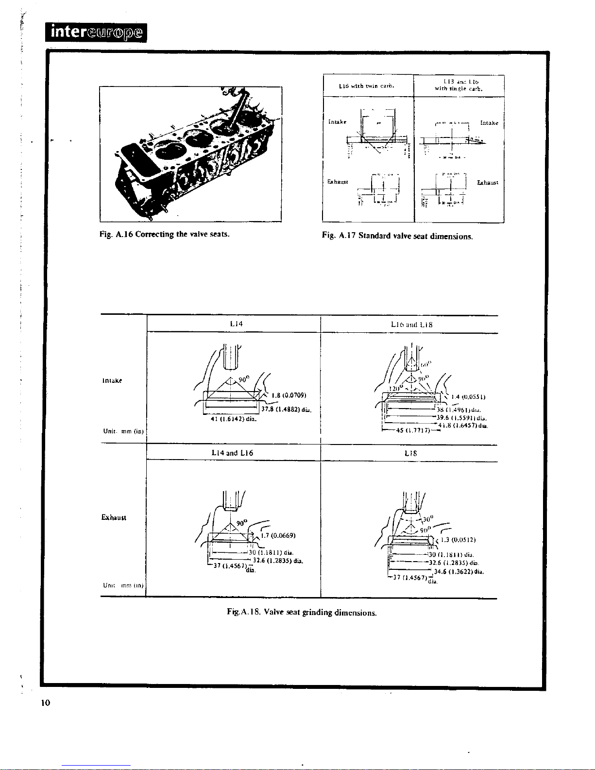
The
valve
seat
surface
must
be
concentric
with
the
guide
bore
and
can
be
corrected
with
the
facing
tool
STll670000
Fig
A
16
using
the
new
valve
guide
as
the
axis
VALVE
SEAT
INSERTS
Replacing
The
valve
seat
inserts should
be
replacedifthey
show
signs
of
pitting
and
excessive
wear
The
inserts
can
be
removed
by
boring
out
to a
depth
which
will
cause
them
to
collapse
although
care
must
be
taken
not
to
bore
beyond
the
bottom
faceofthe
recess
in
the
cylinder
head
Select
the
valve
seat
inserts
and
check
the
outer
diameters
Machine
the
recess
in
the
cylinder
headtothe following
dimensions
at
room
temperature
9
it
r
inter
iJ
i
@
Pl
Fig
A
16
Correcting
the
valve seats
Li4
lnlakt
t1
c
r
I
I
37
8
1
4882
di
410
6142
dia
Unit
rnrn
in
L14
and
L16
Exhaust
Ct
rill
I
II
ill
300
1Bll
du
l
32
6
1
2835
dia
3714561
dia
Unll
In
Llb
thtwin
1
13
Ut
WiTh
Ie
ro
rLl
Incak
h
C
1
q
J
j
Exhaust
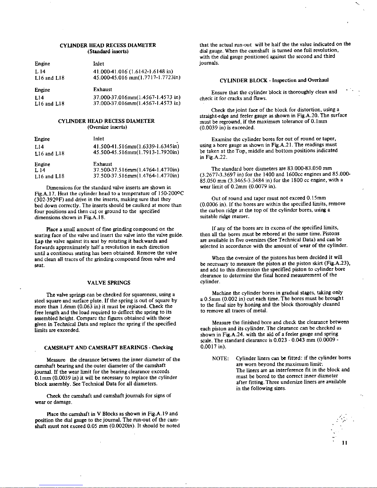
Fig
AIStandard
valve
seat
dimensions
Uland
liS
11tJ
1l
ioo
l
j
14
u
055i1
r
m
JA
9bIJUI4
l
9
611
559lldi
a
4L80
6457
dlll
45J1717
liS
311
fJ
90o
LJ
1300512
r
1
II
I
i
30nIl
i1
I
tlla
32
60
2835
di
L
3461
3622
dla
37
1
4561lia
Fig
A
IS
Valve
at
grinding
dimensions
10
CYUNDER
HEAD
RECESS
DIAMETER
Standard
inoerts
Engine
L14
Ll6
and
Ll8
Inlet
41
000410161614216148
in
45
00045016
mm
1
77l7
1
77231n
Engine
Ll4
Ll6
and
Ll8
Exhaust
37
00037016mm1456714573
in
37
000
37
016mm
l
456714573
in
CYLINDER
HEAD
RECESS
DIAMETER
Oversize
inserts
Engine
Ll4
Ll6andLl8
Inlet
41
500
41
516mm
l
633916345in
45
S0045516mmI791317920in
Engine
L14
Ll6andLl8
Exhaust
37
50037516mm
1
4764
14770in
37
500
37
516mm
1
4764
l4770in
Dimensions
for
the
standard
valve
inserts
are
shown
in
Fig
A
17
Heat
the
cylinder
head
to
a
temperature
of
ISO 20DOC
302
3920F
and
driveinthe
inserts
making
sure
that
they
bed
down
correctly
The
inserts
should
be
caulked
at
more
than
four
positions
and
then
cuf
or
ground
to
the
specified
dimensions
shown
in
Fig
A
IS
Placeasmall
amount
of
fine
grinding
compound
on
the
seating
face
of
the
valve
and
insert
the
valve
into
the
valve
guide
Lap
the
valve
against
its
seat
by
rotating
it
backwards
and
forwards
approximately
halfarevolution
in
each
direction
untilacontinous
seating
has
been
obtained
Remove
the
valve
and
clean
all
traces
of
the
grinding
compound
from
valve
and
seat
VALVE
SPRINGS
The
valve
springs
can
be
checked
for
squareness
using
a
steel
square
and
surface
plate
If
the
spring
is
out
of
square
by
more
than16mm0063init
must
be
replaced
Check
the
free
length
and
the
load
required
to
deflect
the
spring
to
its
assembled
height
Compare
the
figures
obtained
with
those
given
in
Technical
Data
and
replace
the
spring
if
the
specified
limits
are
exceeded
CAMSHAFT
AND
CAMSHAFT
BEARINGS
Checking
Measure
the
clearance
between
the
inner
diameter
of
the
camshaft
bearing
and
the
outer
diameter
of
the
camshaft
journal
If
the
wear
limit
for
the
bearing
clearance
exceeds
O
lmm00039init
will
be
necessary
to
replace
the
cylinder
block
assembly
See
Technical
Data
for
all
diameters
Check
the
camshaft
and
camshaft
journals
for
signs
of
wear
or
damage
ace
the
camshaft
in V
Blocksasshown
in
Fig
A19and
position
the
dial
gauge
to
the
journal
The
runout
of
the
cam
shaft
must
not
exceed
0 05
mm
0
0020in
It
should
be
noted
that
the
actual
run
out
will
be
half
the the
value
indicated
on
the
dial
gauge
When
the
camshaft
is
turned
one
full
revolution
with
the
dial
gauge
positioned
against
the
second
and
third
journals
CYLINDER
BLOCK
Inspection
and
Overhaul
Ensure
that
the
cylinder
block
is
thoroughly
clean
and
checkitfor
cracks
and
flaws
Check
the
joint
faceofthe
block
for
distortion
using
a
straight
edge
and
feeler
gauge
as
shown
in
Fig
A20The
surface
must
be
reground
if
the
maximum
tolerance
ofOlmm
0
0039
inisexceeded
Examine
the
cylinder
bores
for
out
of round
or
taper
using
a
bore
gauge
as
shown
in
Fig
A21The
readings
must
be
takenatthe
Top
middle
and
bottom
positions
indicated
in
Fig
A
22
The
standard
bore
diameters
are
83
000
83
050
rom
3
267733697
in
for
the
1400
and
1600cc
engines
and85000
85
050
mm
3
346533484
in
for
the
1800
cc
engine
with
a
wear
limit
of02mm00079
in
Outofround
and
taper
must
not
exceed015mm
0
0006
inIfthe
bores
are
within
the
specified
limits
remove
the
carbon
ridge
at
the
top
of
the
cylinder
bores
wring
a
suitable
ridge
reamer
If
any
of
the
bores
are
in
excess
of
the
specified
limits
then
all
the
bores
must
be
rebored
at
the
same
time
Pistons
are
available
in
five
oversizes
See
Technical
Data
and
can
be
selectedinaccordance
with
the
amount
of
wear
of
the
cylinder
When
the
oversizeofthe
pistons
has
been
decideditwill
be
necessary
to
measure
the
piston
at
the
piston
skirt
Fig
A
23
and addtothis
dimension
the
specified
pistontocylinder
bore
clearance
to
determine
the
final
honed
measurement
of
the
cylinder
Machine
the
cylinder
bores
in
gradual
stages
taking
only
a
0
5mm
0
002
in
cut
each
time
The
bores
must
be
brought
to
the
final
size
by
honing
and
the
block
thoroughly
cleaned
to
remove
all
traces
of
metal
Measure
the
finished
bore
and
check
the
clearance
between
each
piston
and
its
cylinder
The
clearance
can
be
checked
as
shown
in
Fig
A24with
the
aid
ofafeeler
gauge
and
spring
scale
The
standard
clearanceis0
0230043
mm
0
0009
0
0017
in
NOTE
Cylinder
liners
can
be
fitted
if
the
cylinder
bores
are
worn
beyond
the
maximum
limit
The
liners
are
an
interference
fitinthe
block
and
must
be boredtothe
correct
inner
diameter
after
fitting
Three
undersize
liners
are
available
in
the
following
sizes
11
y
t
interCE
MI
D
liPl
E
r
i
J
r
i
1
4
1
r
l
I
I
I
I
QJJ
I
kigthe
camshaft
for
run
out
Fig
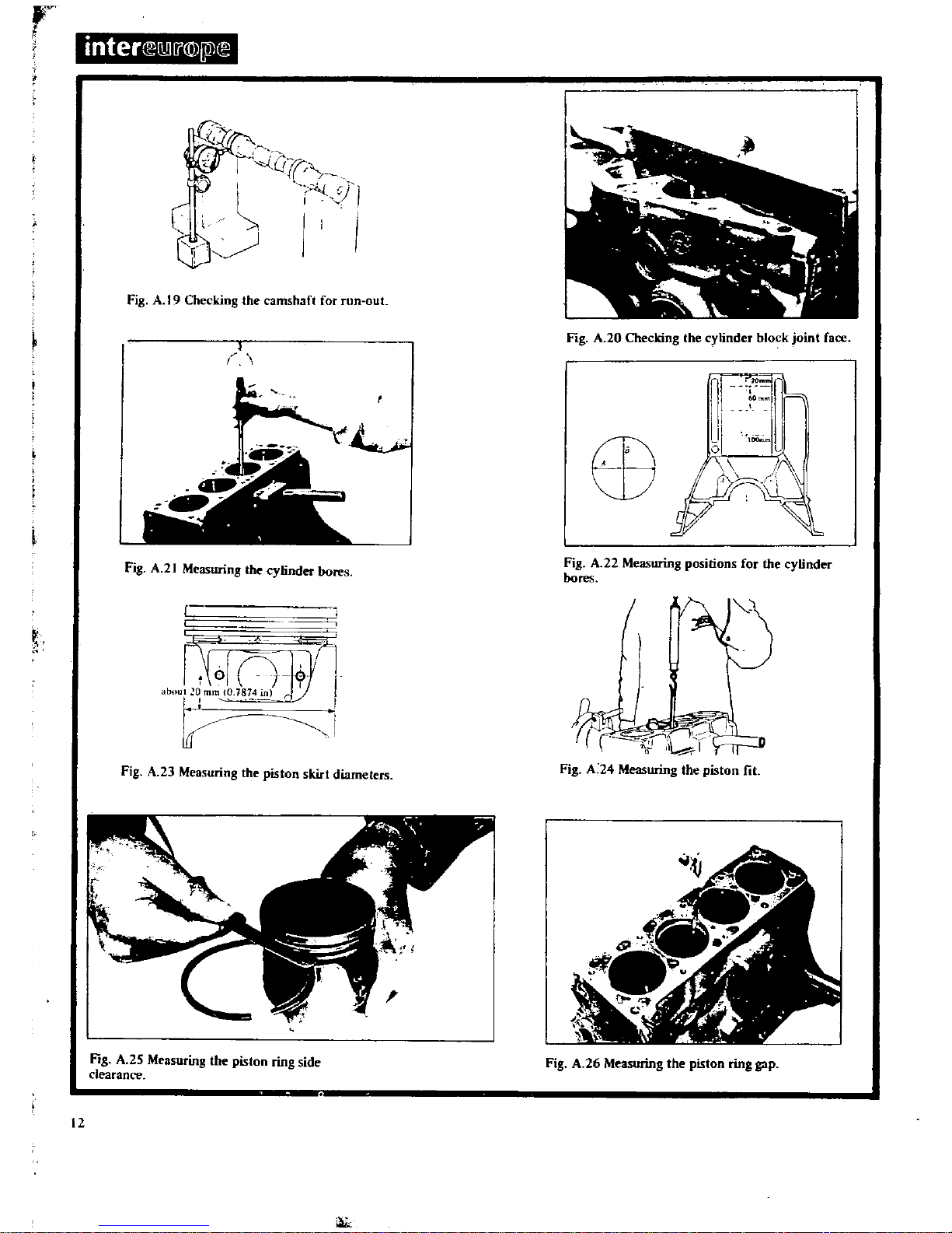
A19Chec
n
I
I
I
y
Ii
der
bores
Fig
A
2
Measuring
lbe
cy
n
1
I
1l
or
r
i
r
mO
1874
r
I
abllUI
O
I
I
Q
ktdiameters
h
pistons
tr
F
A
23
Measunng
t
e
g
the
piston
ring
side
fi
A
25
Measurmg
g
clearance
12
k
oint
face
I
der
bloc
J
ki
gthecym
A20Chec
n
FIg
1
7
rb
I
tinder
ositions
for
the
cy
A
22
Measunng
p
F
g
bores
the
piston
ring
gap
A
26
Measunng
F
g
OUTER
DIAMETER
4
0mm01575
in
Undersize
4
5mm01772inUndersize
5
Omm
0
1969inUndersize
87
0008705mm3425234272
in
8750
87
55mm3444934468
in
880088
05mm
3
4646
3
4665
in
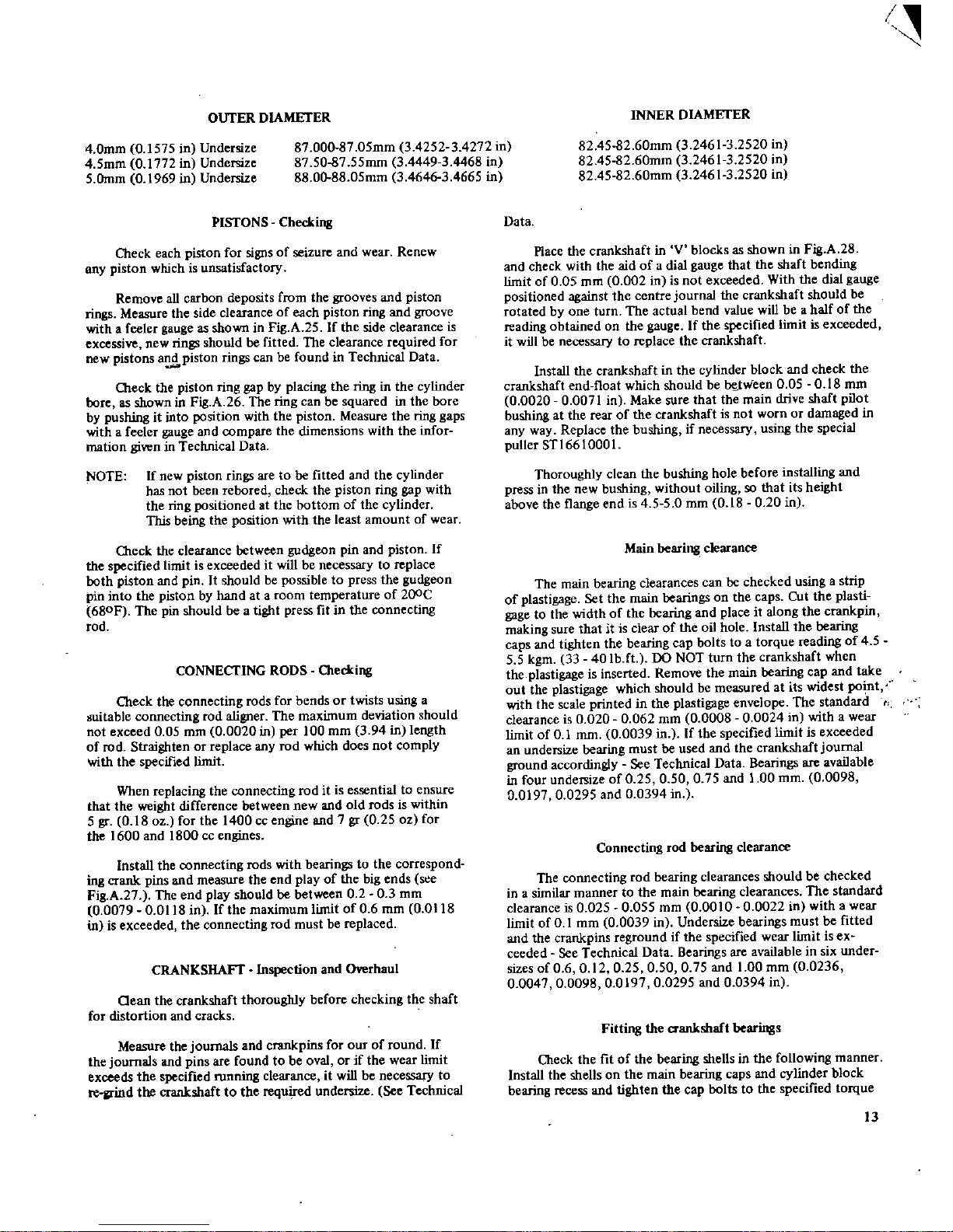
PISTONS
Checking
Check
each
piston
for
signs
of
seizure
and
wear
Renew
BIlY
piston
which
is
unsatisfactory
Remove
all
carbon
deposits
from
the
grooves
and
piston
rings
Measure
the
side
clearance
of
each
piston
ring
and
groove
withafeeler
gauge
as
shown
in
Fig
A
25Ifthe
side
clearance
is
excessive
new
rings
should
be
fitted
The clearance
required
for
new
pistons
a
piston
rings
can
be
foundinTechnical
Data
Check
the
piston
ring
gap
by
placing
the
ring
in
the
cylinder
boreasshown
in
Fig
A26The
ring
can
be
squared
in
the
bore
by
pushing
it
into
position
with
the
piston
Measure
the
ring
gaps
with a
feeler
gauge
and
compare
the
dimensions
with
the
infor
mation
given
in
Technical
Data
NOTE
Ifnew
piston
rings
are
to
be
fitted
and
the
cylinder
has
not
been
rebafed
check
the
piston
ring
gap
with
the
ring
positioned
at
the
bottom
of
the
cylinder
This
being
the
position
with
the
least
amount
of
wear
O1eck
the
clearance
between
gudgeon
pin
and
piston
If
the
specified
limitisexceededitwill
be
necessary
to
replace
both
piston
and
pin
It
should
be
possible
to
press
the
gudgeon
pin
into
the
piston
by
hand
at a
room
temperature
of
200C
680F
The
pin
should
be
a
tight
press
fitinthe
connecting
rod
CONNECTING
RODS
O1ecking
Cleck
the
connecting
rods
for
bendsortwists
using
a
guitable
connecting
rod
aligner
The
maximum
deviation
should
not
exceed005
mm
0
0020
in
per
100
mm
394in
length
of
rod
Straightenorreplace
any
rod
which
does
not
comply
with
the
specified
limit
When
replacing
the
connecting
roditis
essential
to
ensure
that
the
weight
difference
between
new
and
old
rodsiswithin
5
gr
0 18
oz
for
the
1400
cc
engine
and
7gr0 25
oz
for
the
1600
and
1800
cc
engines
Install
the
connecting
rods
with
bearings
to
the
correspond
ing
crank
pins
and
measure
the
end
play
of
the
big
ends
s
e
Fig
A
27
The
end
play
should
be
between0203
mm
0
0079
0
0118
in
fthe
maximum
limitof0
6
mm
0
Ql18
inisexceeded
the
connecting
rod
must
be
replaced
CRANKSHAFT
Inspection
and
Overhaul
aean
the
crankshaft
thoroughly
before
checking
the
shaft
for
distortion
and
cracks
Measure
the
journals
and
crankpins
for
our
of round
If
the
journals
and
pins
are
foundtobe
oval
or
if
the
wear
limit
exceeds
the
specified
fUnning
clearance
it
will
be
necessary
to
re
llrind
the
crankshaft
to
the
required
undersize
See
Technical
I
INNER
DIAMETER
82
45 82
60mm
3
24613
2520
in
824S82
60mm
3
24613
2520
in
824S82
60mm
3
24613
2520
in
Data
Place
the
crankshaft
inVblocksasshown
in
Fig
A
28
and
check
with
the aid
ofadial
gauge
that
the
shaft
bending
limitof0 05
mm
0
002inis
not
exceeded
With
the
dial
gauge
positioned
against
the
centre
journal
the
crankshaft
should
be
rotated
by
one
turn
The
actual
bend
value
will
beahalfofthe
reading
obtained
on
the
gauge
If
the
specified
limit
is
exceeded
it
will
be
necessary
to
replace
the
crankshaft
Install
the
crankshaft
in
the
cylinder
block
and
check
the
crankshaft
end
float
which
should
bebeJ
Yieen
0 05 0
18
mm
0
0020
0
0071
in
Make
sure
that
the
main drive
shaft
pilot
bushing
at
the
rear
of
the
crankshaft
is
not
worn
or
damaged
in
any
way
Replace
the
bushing
if
necessary
using
the
special
puller
STl 66
1000
I
Thoroughly
clean
the
bushing
hole
before
installing
and
press
in
the
new
bushing
without
oiling
so
that
its
height
above
the
flange
endis4
5 5
0
mm
018020in
Main
bearing
clearance
The main
bearing
clearances
can
be
checked
usingastrip
of
plastigage
Set
the
main
bearings
on
the
caps
Cut
the
plasti
gage
to
the
width
of
the
bearing
and
place
it
along
the
crankpin
making
sure
thatitis
clearofthe
oil
hole
Install
the
bearing
caps
and
tighten
the
bearing
cap
bolts
to
a
torque
reading
of
4
5
5 5
kgm
33
40Ibft
DO
NOT
turn
the
crankshaft
when
the
plastigage
is
inserted
Remove
the
main
bearing
cap
and
take
out
the
plastigage
which
should
be
measured
at
its
widest
po
t
with
the
scale
printed
in
the
plastigage
envelope
The
standard
clearanceis0
0200062
mm
0
0008
0
0024
in
with
a
wear
limit
of01
mm
0
0039
in
If
the
specified
limit
is
exceeded
an
undersize
bearing
must
be
used
and
the
crankshaft
journal
ground
accordingly
See
Technical
Data
Bearings
are
available
in
four
undersize
of
0 25 0
50 0 75
and100
mm
0
0098
0
019700295
and00394
in
Connecting
rod
bearing
clearance
The
connecting
rod
bearing
clearances
should
be
checked
in a
similar
manner
to
the
main
bearing
clearances
The
standard
clearanceis0
0250055
mm
0
001000022
in
with
a
wear
limit
of01
mm
0
0039
in
Undersize
bearings
must
be
fitted
and
the
crankpins
reground
if
the
specified
wear
limit
is
ex
ceeded
See
Technical
Data
Bearings
are
available
in
six
under
sizes
of06012
0 25 0 50 0 75
and
1
00
mm
0
0236
0
004700098
0
019700295
and00394
in
Fitting
the
crankshaft
bearings
Cb
eck
the
fitofthe
bearing
shellsinthe
following
manner
Install
the
shellsonthe
main
bearing
caps
and
cylinder
block
bearing
recess
and
tighten
the
cap
boltstothe
specified
torque
13
inter
Q1I
f
Q
I
ll
oJ
Fig
A
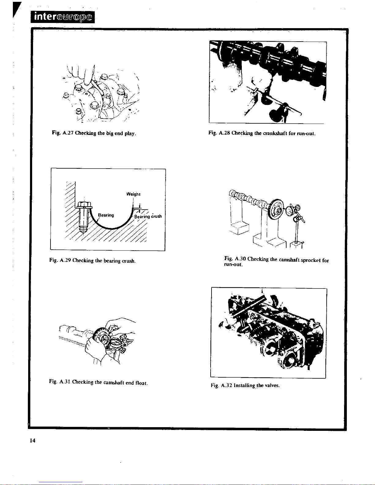
27
Olecking
the
big
end
play
Fig
A
28
Checking
the
crankshaft
for
runout
Weight
Fig
A
29
Checking
the
bearing
crush
Fig
A
30
Checking
the
camshaft
sprocket
for
runout
Fig
A
31
OIecking
the
camshaft
end
float
Fig
A
32
Installing
he
valves
14
reading
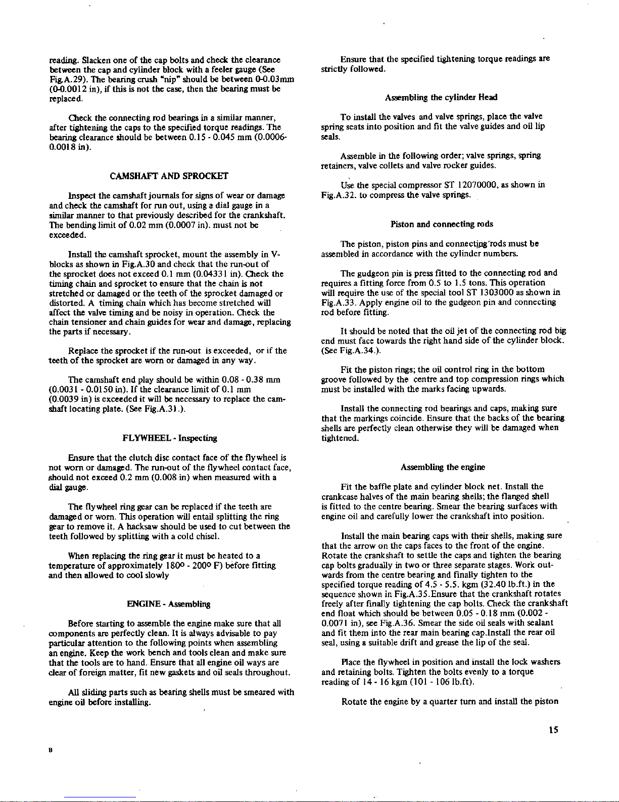
Slacken
one
of
the
cap
bolts
and
check
the
clearance
between
the
cap
and
cylinder
block
with a
feeler
gauge
See
Fig
A
29
The
bearing
crush
nip
should
be
between
00
03mm
00
0012
inifthis
is
not
the
case
then
the
bearing
must
be
replaced
beck
the
connecting
rod
bearings
in a
similar
manner
after
tightening
the
caps
to
the
specified
torque
readings
The
bearing
clearance
shouldbebetween0150045
mm
0
0006
0
0018
in
CAMSIIAFf
AND
SPROCKET
Inspect
the
camshaftjoumals
for
signs
of
wear
or
damage
and
check
the
camshaft
for
run
out
using
a
dial
gauge
in a
similar
manner
to
that
previously
described
for
the
crankshaft
The
bending
limitof0 02
mm
0
0007
in
must
not
be
exceeded
Install
the camshaft
sprocket
mount
the
assembly
in
V
blocksasshown
in
Fig
A
30
and
check
that
the
runout
of
the
sprocket
does
not
exceed01
mOl
0
04331
in
O1eck
the
timing
chain
and
sprocket
to
ensure
that
the
chain
is
not
stretched
or
damaged
or
the
teethofthe
sprocket
damaged
or
distorted
A
timing
chain
which
has
become
stretched
will
affect
the
valve
timing
and
be
noisyinoperation
Check
the
chain
tensioner
and
chain
guides
for
wear
and
damage
replacing
the
parts
if
necessary
Replace
the
sprocket
if
the
runout
is
exceeded
or
if
the
teethofthe
sprocket
are
worn
or
damaged
in
any
way
The
camshaft
end
play
should
be
within
0 08038
mm
0
0031OoI50
inIfthe
clearance
limitof0
1
mm
0
0039
inisexceededitwill
be
necessary
to
replace
the
cam
shaft
locating
plate
See
Fig
A
3l
FLYWHEEL
Inspecting
Ensure
that
the
clutch
disc
contact
face
of
the
flywheel
is
not
worn
or
damaged
The
runout
of
the
flywheel
contact
face
should
not
exceed02
mOl
0
008inwhen
measured
with
a
dial
gauge
The
flywheel
ring
gear
can
be
replaced
if
the
teeth
are
damaged
or
worn
This
operation
will
entail
splitting
the
ring
gear
to
remove
itAhacksaw
should
be
used
to
cut
between
the
teeth
followed
by
splitting
withacold
chisel
When
replacing
the
ring
gear
it
must
be
heated
to
a
temperature
of
approximately
1800 2000Fbefore
fitting
and
then
allowed
to
cool
slowly
ENGINE
Assembling
Before
starting
to
assemble
the
engine
make
sure
that
all
components
are
perfectly
cleanItis
always
advisable
to
pay
particular
attention
to
the
following
points
when
assembling
an
engine
Keep
the
work
bench
and
tools
clean
and
make
sure
that
the
tools
are
to
hand
Ensure
that
all
engine
oil
ways
are
clear
of
foreign
matter
fit
new
gaskets
and
oil
seals
throughout
All
sliding
parts
such
as
bearing
shells
must
be
smeared
with
engine
oil
before
installing
B
Ensure
that
the
specified
tightening
torque
readings
are
strictly
followed
A
mbling
the
cylinder
Head
To
install
the
valves
and
valve
springs
place
the
valve
spring
seats
into
position
and
fit
the
valve
guides
and
oil
lip
seals
Assemble
in
the following
order
valve
springs
spring
retainers
valve
collets
and
valve
rocker
guides
Use
the
special
compressor
ST
12070000
as
shown
in
Fig
A
32
to
compress
the
valve
springs
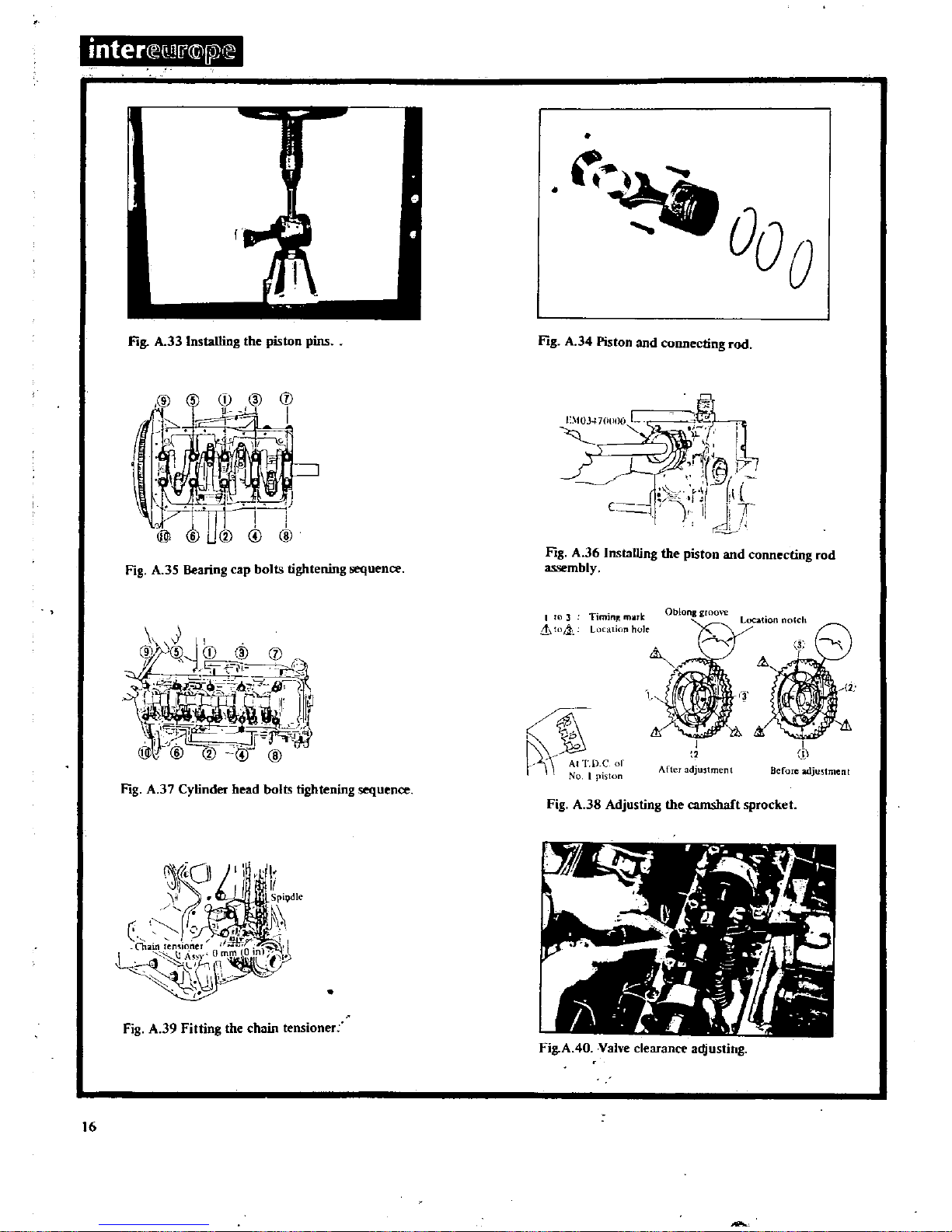
Piston
and
connecting
rods
The
piston piston
pins
and
connectiJ1
rods
must
be
assembled
in
accordance
with
the
cylinder
numbers
The
gudgeon
pin
is
press
fitted
to
the
connecting
rod
and
requiresafitting
force
from
05to1
5
tons
This
operation
will
require
the
use
of
the
special
tool
ST
1303000
as
shown
in
Fig
A
33
Apply
engine
oil to
the
gudgeon
pin
and
connecting
rod
before
fitting
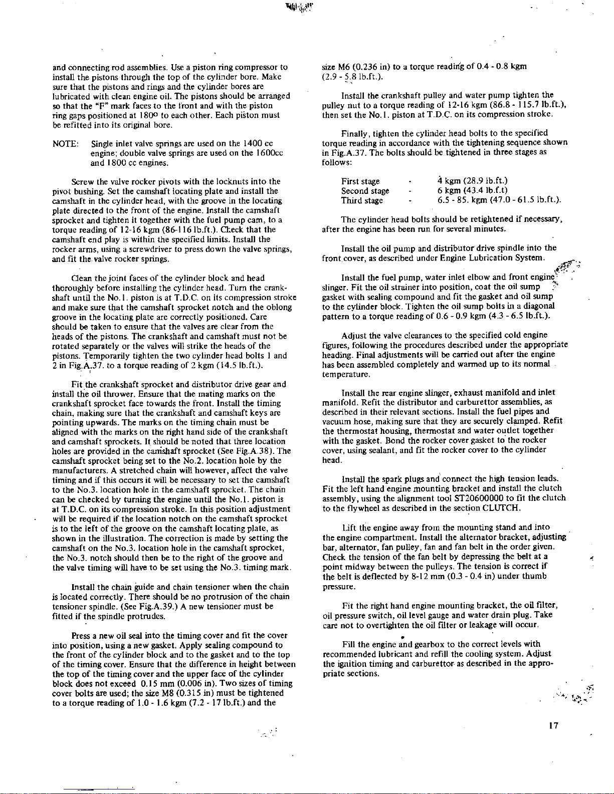
It
should
be noted
that
the
oil
jet
of
the
connecting
rod
big
end
must
face
towards
the
right
hand
sideofthe
cylinder
block
See
Fig
A
34
Fit
the
piston
rings
the
oil
control
ring
in
the
bottom
groove
followed
by
the centre
and
top
compression
rings
which
must
be
installed
with
the
marks
facing
upwards
Install
the
connecting
rod
bearings
and
caps
making
sure
that
the
markings
coincide
Ensure
that
the
backsofthe
bearing
shells
are
perfectly
clean
otherwise
they
will
be
damaged
when
tightened
Assembling
the
engine
Fit
the
baffle
plate
and
cylinder
block
net
Install
the
crankcase halvesofthe
main
bearing
shells
the
flanged
shell
is
fitted
to
the
centre
bearing
Smear
the
bearing
surfaces
with
engine
oil
and
carefully
lower
the
crankshaft
into
position
Install
the
main
bearing
caps
with
their
shells
making
sure
that
the
arrow
on
the
caps
facestothe
front
of
the
engine
Rotate
the
crankshaft
to
settle
the
caps
and
tighten
the
bearing
cap
bolts
gradually
in
two
or
three
separate
stages
Work
out
wards
from
the
centre
bearing
and
finally
tighten
to
the
specified
torque
reading
of45 5 5
kgm
3240
Ib
ft
in
the
sequence
shown
in
Fig
A35Ensure
that
the
crankshaft
rotates
freely
after
finally
tightening
the
cap
bolts
Check
the
crankshaft
end
float
which
should
be
between
0 05 0
18
mm
0
002
0
0071
in
see
Fig
A
36
Smear
the
side
oil
seals
with
sealant
and
fit
them
into
the
rear
main
bearing
cap
Install
the
rear
oil
seal
using
a
suitable
drift
and
grease
the
lip
of
the
seal
Place
the
flywheel
in
position
and
install
the
lock
washers
and
retaining
baits
Tighten
the
bolts
evenly
to a
torque
reading
of
14 16
kgm
101
106Ib
ft
Rotate
the
engine
by
a
quarter
turn
and
install
the
piston
15
inter
Q1
jX
E
Fig
A
33
Installing
the
piston
pins
Fig
A
34
Piston
and
connecting
rod
cD
I
E
103470t
O
L
I
1
I
riC
J
lt
I
t
1
1
C
j
I
If
I
r
Fig
A
35
Bearing
cap
bolts
tightening
sequence
Fig
A
36
Installing
the
piston
and
connecting
rod
assembly
J
0
k2
CD
1 1
r
1
P
l
b
S
LM
J
Jr
T9T
J
I
J
@@@C@@
I
3
TimJn
mark
Lt
j
Location
hole
Oblonl
groon
I
I
Afteradju5tment
1
i
Before
adjustment
At
TDCor
No
I
piston
Fig
A
37
Cylinder
head
bolts
tightening
sequence
Fig
A
38
Adjusting
the camshaft
sprocket
Fig
A
39
Fitting
the
chain
tensioner
Fig
A40Valve
clearance
adjusting
16
h
W
and
connecting
rod
assemblies
Use
a
piston
ring
compressor
to
install
the
pistons
through
the
top
of
the
cylbder
bore
Make
sure
that
the
pistons
and
rings
and
the
cylinder
bores
are
lubricated
with
clean
engine
oil
The
pistons
should
be
arranged
so
that
the
F
mark
faces
to
the
front
and
with
the
piston
ring
gaps
positioned
at
1800toeach
other
Each
piston
must
be
refitted
into
its
original
bore
NOTE
Single
inlet
valve
springs
are
usedonthe
1400
cc
engine
double
valve
springs
are
usedonthe
1600cc
and 1800
cc
engines
Screw
the
valve
rocker
pivots
with
the
locknuts
into
the
pivot
bushing
Set
the
camshaft
locating
plate
and
install
the
camshaft
in
the
cylinder
head
with
the
groove
in
the
locating
plate
directed
to
the
frontofthe
engine
Install
the
camshaft
sprocket
and
tightenittogether
with
the
fuel
pump
earn
to
a
torque
reading
of
12 16
kgm
86
116
IbJt
a
eck
that
the
camshaft
end
play is
within
the
specified
limits
Install
the
rocker
arms
using
a
screwdriver
to
press
down
the
valve
springs
and
fit
the
valve
rocker
springs
Gean
the
joint
facesofthe
cylinder
block
and
head
thoroughly
before
installing
the
cylinder
head
Turn
the
crank
shaft
until
the
No
1
piston
is
at
T
D Conits
compression
stroke
and
make
sure
that
the
camshaft
sprocket
notch
and
the
oblong
groove
in
the
locating
plate
are
correctly
positioned
Care
should
be
taken
to
ensure
that
the
valves
are
clear
from
the
headsofthe
pistons
The
crankshaft
and
camshaft
must
not
be
rotated
separately
or
the
valves
will
strike
the
headsofthe
pistons
Temporarily
tighten
the
two
cylinder
head
bolts1and
2
in
Fig
A
37
to
a
torque
reading
of
2
kgm145
lb
ft
Fit
the
crankshaft
sprocket
and
distributor
drive
gear
and
install
the
oil
thrower
Ensure
that
the
mating
marksonthe
crankshaft
sprocket
face
towards
the
front
Install
the
timing
chain
making
sure
that
the
crankshaft
and
camshaft
keys
are
XJinting
upwards
The
marks
on
the
timing
chain
must
be
aligned
with
the
marksonthe
right
hand
sideofthe
crankshaft
and
camshaft
sprockets
It
should
be
noted that
three
location
holes
are
provided
in
the
camshaft
sprocket
See
Fig
A38The
camshaft
sprocket
being
set
to
theNo2
location
holebythe
manufacturers
A
stretched
chain
will
however
affect
the
valve
timing
andifthis
occurs
it
will
be
necessary
to
set
the
camshaft
to
theNo3
location
holeinthe
camshaft
sprocket
The
chain
can
be
checked
by
turning
the
engine
until
the
No
1
piston
is
at
TDConits
compression
stroke
In
this
position
adjustment
will
be
required
if
the
location
notch
on
the
camshaft
sprocket
istothe
leftofthe
groove
on
the
camshaft
locating
plate
as
showninthe
illustration
The
correction
is
made
by
setting
the
camshaft
on
the
No3location
holeinthe
camshaft
sprocket
theNo3
notch
should
then
betothe
right
of
the
groove
and
the
valve
timing
will
havetobe
set
using
theNo3
timing
mark
Install
the
chain
guide
and
chain
tensioner
when
the
chain
is
located
correctly
There
should
be
no
protrusion
of
the
chain
tensioner
spindle
See
Fig
A39A
new
tensioner
must
be
fittedifthe
spindle
protrudes
Press
a
new
oil
seal
into
the
timing
cover
and
fit
the
cover
into
position
using
a
new
gasket
Apply
sealing
compound
to
the
front
of
the
cylinder
block
andtothe
gasket
andtothe
top
of
the
timing
cover
Ensure
that
the
difference
in
height
between
the
top
of
the
timing
cover
and
the
upper
faceofthe
cylinder
block
does
not
exceed
0
15
mm
0
006
in
Two
sizes
of
timing
cover
bolts
are
used
the
size
M80315
in
must
be
tightened
to
a
torque
reading
of1016
kgm
7
217Ibftand
the
size
M60236
in to
a
torque
reading
of
0 4 0
8
kgm
2 9
81b
ft
Install
the
crankshaft
pulley
and
water
pump
tighten
the
pulley
nut
to
a
torque
reading
of
12 16
kgm
868115
7Ib
ft
then
set
the
No
1
piston
at
TDConits
compression
stroke
Finally
tighten
the
cylinder
head
bolts
to
the
specified
torque
reading
in
accordance
with
the
tightening
sequence
shown
in
Fig
A3The
bolts
should
be
tightened
in
three
stages
as
follows
First
stage
Second
stage
Third
stage
4
kgm
28
9
lbJt
6
kgm
434IbJ
t
6 5
85
kgm
47 0615lb
ft
The
cylinder
head
bolts
should
be
retightened
if
necessary
after
the
engine
has
been
run
for
several
minutes
Install
the
oil
pump
and
distributor
drive
spindle
into
the
front
cover
as
described
under
Engine
Lubrication
System
r
rf
i
Install
the
fuel
pump
water
inlet
elbow
and
front
engine
slinger
Fit
the
oil
strainer
into
position
coat
the
oil
sump
gasket
with
sealing
compound
and
fit
the
gasket
and
oil
sump
to
the
cylinder
block
Tighten
the
oil
sump
bolts
in a
diagonal
pattern
to
a
torque
reading
of06
0 9
kgm
43 65
IbJt
Adjust
the
valve
clearances
to
the
specified
cold
engine
ftgures
following
the
procedures
described
under
the
appropriate
heading
Final
adjustments
willbecarried
out
after
the
engine
has
been
assembled
completely
and
warmed
up
to
its
nonnal
temperature
Install
the
rear
engine
slinger
exhaust
manifold
and
inlet
manifold
Refit
the
distributor
and
carburettor
assemblies
as
described
in
their
relevant
sections
Install
the
fuel
pipes
and
vacuum
hose
making
sure
that
they
are
securely
cl
ped
Refit
the
thermostat
housing
thermostat
and
water
outlet
together
with
the
gasket
Bond
the
rocker
cover
gasket
to
the
rocker
cover
using
sealant
and
fit
the
rocker
cover
to
the
cylinder
head
Install
the
spark
plugs
and
connect
the
high
tension
leads
Fit
the
left
hand
engine
mounting
bracket
and
install
the
clutch
assembly
using
the
alignment
tool
ST20600000
to fit
the
clutch
to
the
flywheel
as
described
in
the
section
ClUfCR
Lift
the
engine
away
from
the
mounting
stand
and
into
the
engine
compartment
Install
the
alternator
bracket
adjusting
bar
alternator
fan
pulley
fan
and
fan
beltinthe
order
given
Check
the
tension
of
the fan
belt
by
depressing
the
belt
at a
point
midwybetween
the
pulleys
The
tension
is
correct
if
the
belt
is
deflected
by
8
12
mm
03
0 4inunder
thumb
pressure
Fit
the
right
hand
engine
mounting
bracket
the
oil
filter
oil
pressure
switch
oil level
gauge
and
water
drain
plug
Take
care
not
to
overtighten
the
oil
nIter
or
leakage
will
occur
Fill
the
engine
and
gearbox
to
the
correct
levels
with
recommended
lubricant
and
refill
the
cooling
system
Adjust
the
ignition timing
and
carburettor
as
described
in
the
appro
priate
sections
17
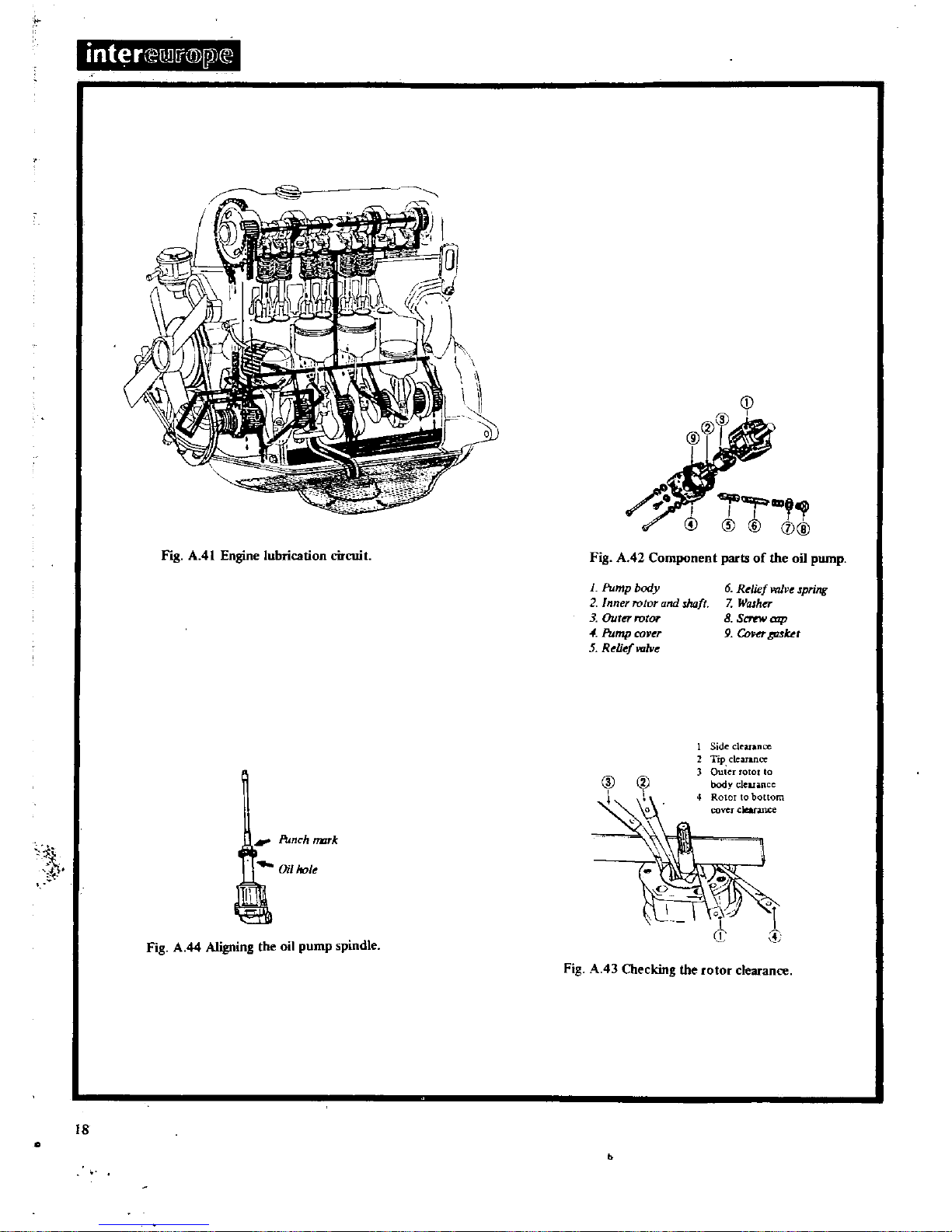
inter
lmi
@
jl
Fig
A
41
Engine
lubrication
circuit
i
Punch
rmrk
Oil
hole
L
Fig
A
44
Aligning
the
oil
pump
spindle
18
II
l
o
CD
I
Fig
A
42
Component
parts
of
the
oil
pump
L
Pump
body
2
Inner
rotor
and
wft
3
OutO
rotor
4
Pump
coper
5
Reliefvalve
6
Relief
valve
Jpring
7
Washer
8
S
alp
9
ConT
613ut
I
Sideclruance
2
TIp
clearance
3
Guier
10
00
body
clearance
t
4
Rotor
to
bottom
cover
cleatance
Fig
A
43
Checking
the
rotor
clearance
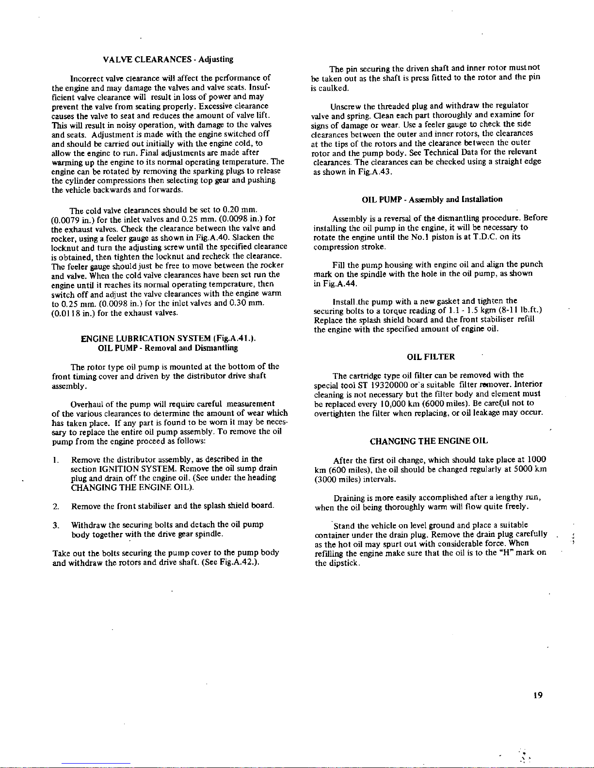
VALVE
CLEARANCES
Adjusting
Incorrect
valve
clearance
will
affect
the
performance
of
the
engine
and
may
damage
the
valves
and
valve
seats
Insuf
ficient
valve
clearance
will
resultinloss
of
power
and
may
prevent
the
valve
from
seating
properly
Excessive
clearance
causes
the
valve
to
seat
and
reduces
the
amount
of
valve
lift
This
will
result
in
noisy
operation
with
damage
to
the
valves
and
seats
Adjustment
is
made
with
the
engine
switched
off
and
should
be
carried
out
initially
with
the
engine
cold
to
allow
the
engine
to
run
Final
adjustments
are
made
after
wanning
up
the
engine
to
its
Donnal
operating
temperature
The
engine
can
be
rotated
by
removing
the
sparking
plugs
to
release
the
cylinder
compressions
then
selecting
top
gear
and
pushing
the
vehicle
backwards
and
forwards
The
cold
valve
clearances
should
be
set
to
0
20
mm
0
0079
in
for
the
inlet
valves
and
0 25
mm
0
0098
in
for
the
exhaust
valves
Check
the
clearance
between
the
valve
and
rocker
using
a
feeler
gauge
as
shown
in
Fig
A40Slacken
the
locknut
and
turn
the
adjusting
screw
until
the
specified
clearance
is
obtained
then
tighten
the
locknut
and
recheck
the
clearance
The
feeler
gauge
should
just
be
free
to
move
between
the
rocker
and
valve
When
the
cold
valve
clearances
have
been
set
run
the
engine
untilitreaches
its
normal
operating
temperature
then
switch
off
and
adjust
the
valve
clearances
with
the
engine
warm
to
0 25
mm
0
0098
in
for
the
inlet
valves
and030
mm
0
0118
in
for
the
exhaust
valves
ENGINE
LUBRICATION
SYSTEM
Fig
A
41
OIL
PUMP
Removal
and
Dismantling
The
rotor
type
oil
pump
is
mounted
at
the
bottom
of
the
front
timing
cover
and
driven
by
the
distributor
drive
shaft
assembly
Overhaul
of
the
pump
will
require
careful
measurement
of
the
various
clearances
to
determine
the
amount
of
wear
which
has
taken
place
If
any
part
is
found
to
be
worn
it
may
be
neces
sary
to
replace
the
entire oil
pump
assembly
To
remove
the
oil
pump
from
the
engine
proceed
as
follows
1
Remove
the
distributor
assembly
as
described
in
the
section
IGNITION
SYSTEM
Remove
the
oil
sump
drain
plug
and
drain
off
the
engine
oil
See
under
the
heading
CHANGING
THE
ENGINE
OIL
2
Remove
the
front
stabiliser
and
the
splash
shield
board
3
Withdraw
the
securing
bolts
and
detach
the
oil
pump
body together
with
the
drive
gear
spindle
Take
out
the
bolts
securing
the
pump
cover
to
the
pump
body
and
withdraw
the
rotors
and drive shaft
See
Fig
A
42
The
pin
securing
the driven
shaft
and
inner
rotor
must
not
00
taken
out
as
the
shaft
is
press
fitted
to
the
rotor
and
the
pin
is
caulked
Unscrew
the
threaded
plug
and
withdraw
the
regulator
valve
and
spring
Oean
each
part
thoroughly
and
examine
for
signsofdamage
or
wear
Useafeeler
gauge
to
check
the
side
clearances
between
the
outer
and
inner
rotors
the
clearances
at
the
tips
of
the
rotors
and
the
clearance
between
the
outer
rotor
and
the
pump
body
See
Technical
Data
for
the
relevant
clearances
The
clearances
can
be
checked
usingastraight
edge
as
shown
in
Fig
A
43
OIL
PUMP
Assembly
and
Installation
Assembly
is
a
reversalofthe
dismantling
procedure
Before
installing
the
oil
pump
in
the
engine
it
will
be
necessary
to
rotate
the
engine
until
the
No
1
piston
isatT
D Conits
compression
stroke
Fill
the
pump
housing
with
engine
oil
and
align
the
punch
markonthe
spindle
with
the
hole
in
the
oil
pump
as
shown
in
Fig
A
44
Install
the
pump
with a
new
gasket
and
tighten
the
securing
bolts
to
a
torque
reading
of
11 15
kgm
81Ilb
ft
Replace
the
splash
shield board
and
the
front
stabiliser
refill
the
engine
with
the
specified
amount
of
engine
oil
OIL
FILTER
The
cartridge
type
oil
filter
can
be
removed
with
the
special
tool
ST
19320000
or
a
suitable
filter
remover
Interior
cleaning
is
not
necessary
but
the
ftIter
body
and
element
must
be
repiaced
every
10
000
km
6000 miles
Be
care
ul
not
to
overtighten
the
filter
when
replacing
or
oil
leakage
may
occur
CHANGING
THE
ENGINE
OIL
After
the
fIrst
oil
change
which
should
take
place
at
1000
km
600
miles
the
oil
should
be
changed
regularly
at
5000
km
3000
miles
intervals
Draining
is
more
easily
accomplished
after
a
lengthy
run
when
the
oil
being
thoroughly
warm
will
flow
quite
freely
Stand
the
vehicle
on
level
ground
and
place
a
suitable
container
under
the
drain
plug
Remove
the
drain
plug
carefully
as
the
hot
oil
may
spurt
out
with
considerable
force
When
refIlling
the
engine
make
sure
that
the
oil
istothe
H
mark
on
the
dipstick
19
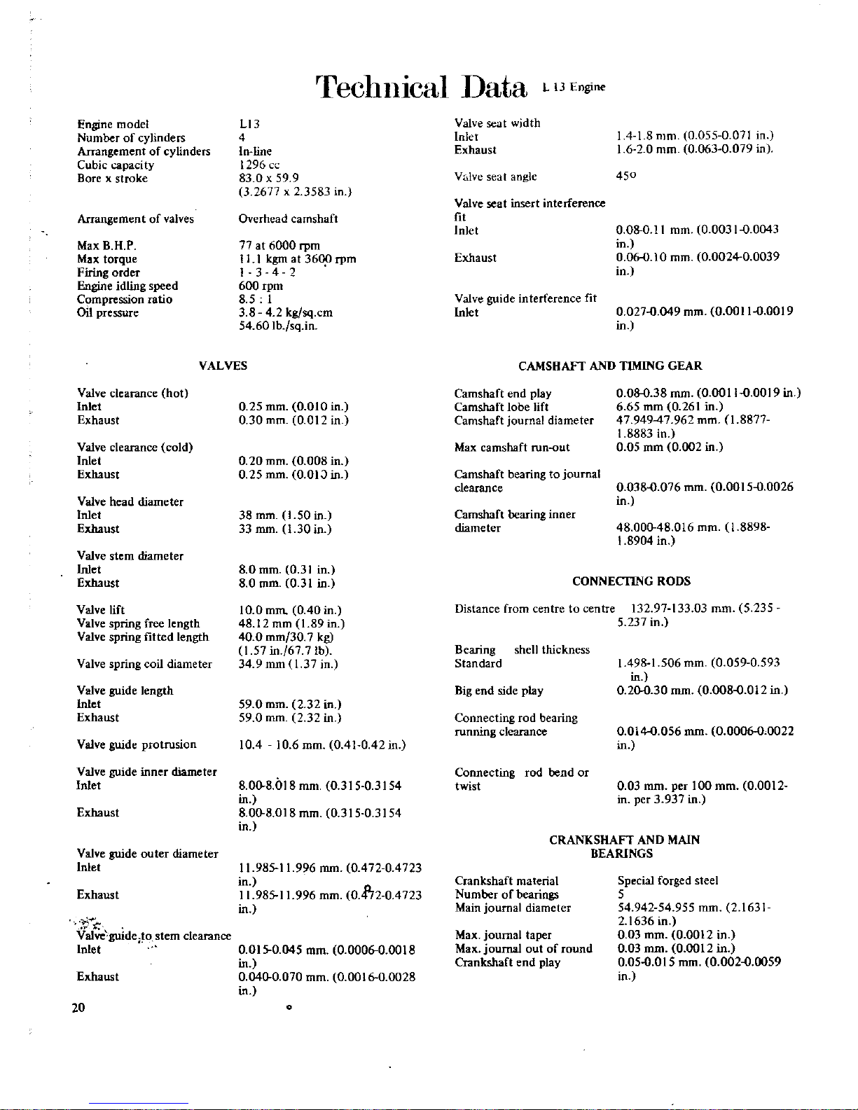
Engine
model
Number
of
cylinders
Arrangement
of
cylinders
Cubic
capaci
ty
Borexstroke
Arrangemen
t
of
valves
MaxBH
P
Max
torque
Firing
order
eidlingspeed
Compression
ratio
Oil
pressure
Valve clearance
hot
Inlet
Exhaust
Valve
clearance
cold
Inlet
Exhaust
Valve
head
diameter
Inlet
Exhaust
Valve
stem
diameter
Inlet
Exhaust
Valve
lift
Valve
spring
free
length
Valve
spring
fitted
length
Valve
spring
coil
diameter
Valve
guide
length
Inlet
Exhaust
Valve
guide
protrusion
rreclll11cal
ata
L
lJEngine
LI3
4
In
line
1296
83 0x59
9
3
2677
x
3583
in
Overhead
camshaft
77at6000
rpm
II
1
kgm
at
3600
rpm
I
342
600
rpm
8 5
1
3 842
kg
sq
em
54
60Ib
sq
in
VALVES
0 25
mm
0
010
in
0 30
mm
0
01
in
0
20
mm
0
008
in
0 25
mm
O
OIJ
in
38
mm
150in
33
mm
1
30
in
8
0
mm
0
31
in
8
0
mm
031in
10 0
mm
040in
48
12
mm
1
89
in
40
0
mm
30
7
kg
1
57
in
67
7
lb
34
9
mm
1
37 in
59 0
mm
2
32
in
59 0
mm
232in
10410 6
mm
041042in
Valve
guide
inner
diameter
Inlet
8008l8
mm
0
31503154
in
Exhaust
8008
018
mm
0
31503154
in
Valve
guide
outer
diameter
Inlet
Exhaust
Valve
guide
to
stem
clearance
Inlet
Exhaust
20
1198511996
mm
0
47204723
in
11
98511996
mm
0
4172
0
4723
in
0
0150045
mm
0
000600018
in
0
0400070
mm
0
001600028
in
Valve
seat
width
Inlet
Exhaust
V
lve
seat
angle
Valve
seat
insert
interference
fit
Inlet
Exhaust
Valve
guide
interference
fit
Inlet
141
8
mm
0
0550071
in
162
0
mm
0
0630079
in
450
0080
11
mm
0
003100043
in
0060
10
mm
0
002400039
in
0
0270049
mm
0
001100019
in
CAMSHAFT
AND
TIMING
GEAR
Camshaft
end
play
Camshaft lobe
lift
Camshaft
journal
diameter
Max
camshaft
runout
Camshaft
bearingtojournal
clearance
Camshaft
bearing
inner
diameter
0080
38
mm
0
0011
0
0019
in
6 65
mm
0
261
in
47
94947962
mm
fI
8877
1
8883
in
0 05
mm
0
002
in
0
0380076
mm
0
001500026
in
48 000
48
016
mm
1
8898
1
8904
in
CONNECTING
RODS
Distance
from
centre
to
centre
13297133
03
mm
5
235
5
237
in
Bearing
shell
thickness
Standard
Big
end
side
play
Connecting
rod
bearing
running
clearance
Connecting
rod
rend
or
twist
1
4981506
mm
0
0590593
in
0200
30
mm
0
0080012
in
0
0140056
mm
0
000600022
in
0 03
mm
per
100
mm
0
0012
in
per
3
937
in
CRANKSHAFT
AND
MAIN
BEARINGS
Crankshaft
material
Number
of
bearings
Main
journal
diameter
Max
journal
taper
Max
journal
out
of round
Crankshaft
end
play
Special
forged
steel
5
54
94254955
mm
2
1631
2
1636
in
0 03
mm
0
0012
in
0 03
mm
0
0012
in
0
050015
mm
0
00200059
in
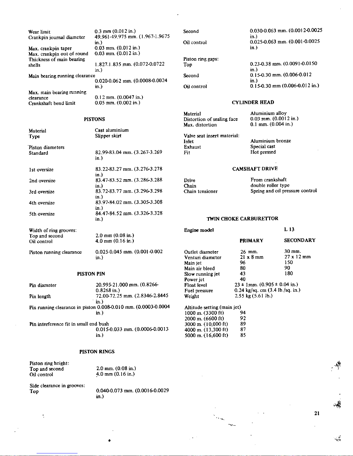
Wear
limit
Crank
pin
journal
diameter
Max
crankpin
taper
Max
crankpin
out
of round
Thickness
of
main
bearing
shells
0
3
mm
0
012
in
49
96149975
mm
1
967
1
9675
in
0 03
mm
0
012
in
0 03
mm
0
012
in
1
8271835
mm
0
07200722
in
Main
bearing
running
clearance
0
0200062
mm
0
0008
0
0024
in
Max
main
bearing
running
clearance
Crankshaft
bend
limit
Material
Type
Piston
diameters
Standard
Istoversize
2nd
oversize
3rd
oversize
4th
oversize
5th
oversize
Width of
ring
grooves
Top
and
second
Oil
control
Piston
running
clearance
0
12
mm
0
0047
in
0 05
mm
0
002
in
PISTONS
Cast
aluminium
Slipper
skirt
82 99 83
04
mm
3
2673269
in
83 228327
mm
3
276
3
278
in
8347
83 52
mm
3
286
3
288
in
83 72 83 77
mm
3
296
3
298
in
83 97 84 02
mm
3
3053308
in
84 47 84 52
mm
3
3263328
in
2
0
mm
0 08
in
4 0
mm
0 16
in
0
0250045
mm
0
0010002
in
PISTON
PIN
Pin
diameter
20
99521000
mm
0
8266
0
8268
in
Pin
length
720072 25
mm
2
8346
2
8445
in
Pin
running
clearance
in
piston
0
0080010
mm
0
000300004
in
Pin
interference
fit
in
small
end
bush
0
0150033
mm
0
000600013
in
Piston
ring
height
Top
and
second
Oil
control
Side
clearance
in
grooves
Top
PISTON RINGS
2
0
mm
0
08 in
4 0
mm
0 16
in
0
0400073
mm
0
001600029
in
Second
Oil
control
Piston
ring
gaps
Top
Second
Oil
control
Material
Distortion
of
sealing
face
Max
distortion
Valve
seat
insert
material
Inlet
Exhaust
Fit
Drive
Chain
Chain
tensioner
0
0300063
mm
0
001200025
in
0
0250063
mm
0
00100025
in
0 23 0 38
mm
0
0091
0
0150
in
0150 30
mm
0
0060012
in
0150
30
mm
0
0060012
in
CYLINDER HEAD
Aluminium
alloy
0
03
mm
0
0012
in
0
1
mm
0
004
in
Aluminium
bronze
Special
cast
Hot
pressed
CAMSHAFT
DRIVE
From
crankshaft
double
roller
type
Spring
and
oil
pressure
control
Engine
model
lWIN
CHOKE
CARBURE
ITOR
Outlet
diameter
Venturi
diameter
Main
jet
Main
air
bleed
Slow
running
jet
Power
jet
Float
level
Fuel
pressure
Weight
Altitude
setting
main
jet
1000
m
3300
ft
94
2000
m
6600
ft
92
3000
m
10
000
ft
89
4000
m
13
300
ft
87
5000
m
16
600
ft
85
PRIMARY
L13
SECONDARY
30mm
27x
12mm
150
90
180
26
mm
21
x8mm
96
80
43
40
23
I
mm
0
905
0 04
in
0 24
kg
sq
em
3
41b
sq
in
2
55kg561lb
1
21
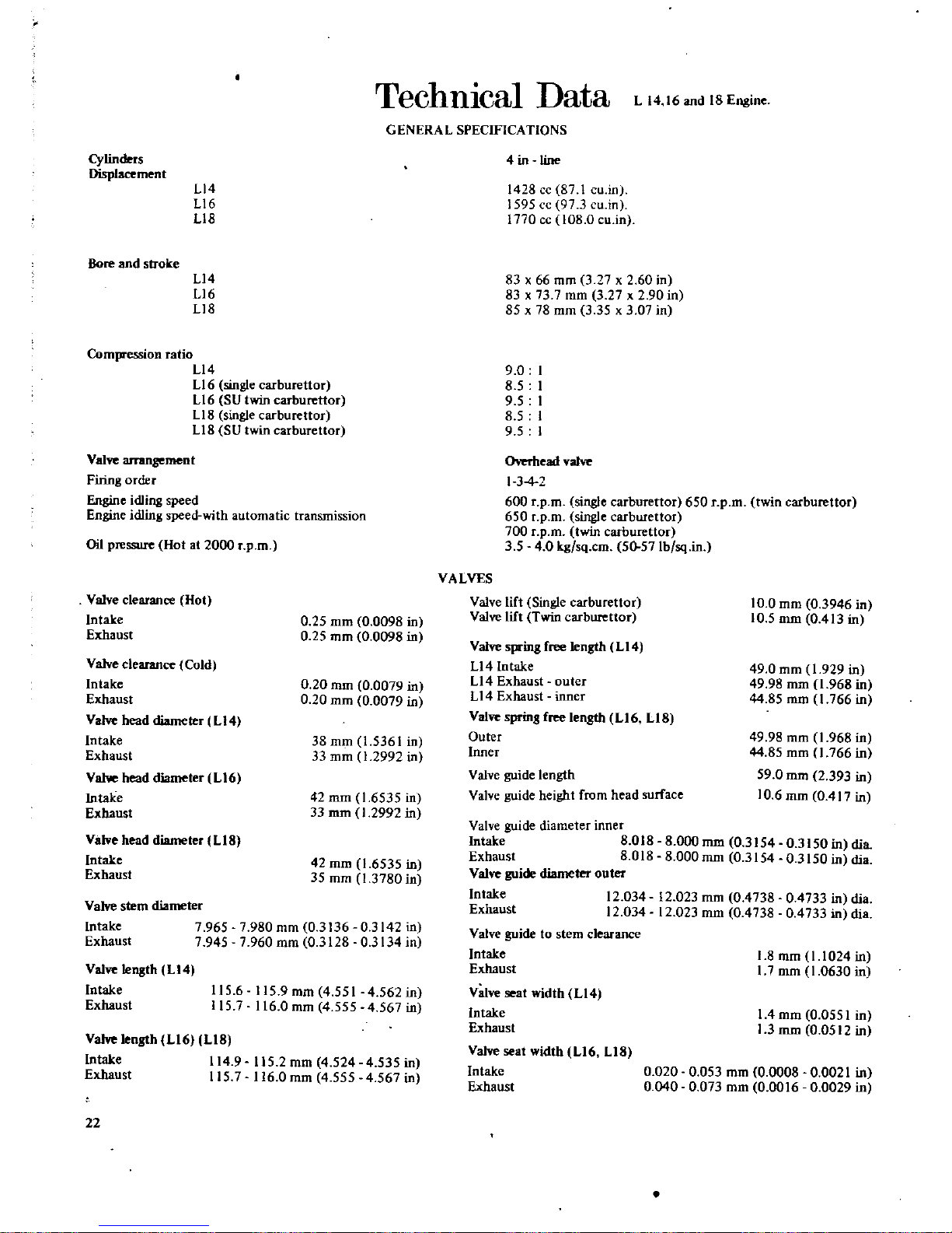
TechnIcal
Data
L
14 16
and
18
Engine
GENERAL
SPECIFICATIONS
Cylinders
Displacement
L14
L16
L18
Bore
and
stroke
L14
L16
Ll8
Compression
ratio
L14
L16
single
carburettor
L16
SU
twin
carburettor
L18
single
carburettor
Ll8
SU
twin
carburettor
Valve
arrangement
Firing
order
e
idling
speed
Engine
idling
speed
with
automatic
transmission
Oil
pressure
Hotat2000
rpm
Valve
clearance
Hot
Intake
Exhaust
0 25
mm
0
0098
in
0 25
mm
0
0098
in
Valve
clearance
Cold
Intake
Exhaust
Va
head
diameter
L14
Intake
Exhaust
Vahoe
head
diameter
L16
Intake
Exhaust
0 20
mm
0
0079
in
0 20
mm
0
0079
in
38
mm
1
5361
in
33
mm
1
2992
in
42
mm
1
6535
in
33
rom
1
2992
in
Valve
head
diameter
L18
Intake
Exhaust
42
mm
1
6535
in
35
mm
1
3780
in
Valve
stem
diameter
Intake
7
9657980
mm
0
3136
0
3142
in
Exhaust
7
9457960
mm
0
312803134
in
Valve
length
L14
Intake
Exhaust
115
6
115
9mm
4
551
4
562in
1157116
0
mm
4
5554567
in
Valve
length
L16
LIB
Intake
114
9
115
2
mm
4
5244535
in
Exhaust
1157116
0
mm
4
5554567
in
22
4inline
1428
cc
87
1cuin
1595
cc
973cu
in
1770
cc
108
0cuin
83x66
mm
3
27x260in
83
x
73
7
mm
3
27x290in
85x7B
mm
3
35x307in
9 0
8 5
9
5
8 5
9 5
Overhead
valve
I
34
600
rpm
single
carburettor
650
rpm
twin
carburettor
650
rpm
single
carburettor
700
rpm
twin
carburettor
354 0
kg
sq
cm
50
57Ib
sq
in
VALVES
Valve
lift
Single
carburettor
Valve
lift
Twin
carburettor
10
0
mm
0
3946
in
10
5
mm
0
413
in
Valve
spring
free
length
LI4
Ll4
Intake
Ll4
Exhaust
outer
L14
Exhaust
inner
Valve
sprin8
free
length
L16
LIB
Outer
Inner
49 0
mm
1
929
in
49 98
mm
1
968
in
44 85
mm
1
766
in
49 98
mm
1
968
in
44 85
mm
1
766
in
59 0
mm
2
393
in
10
6
mm
0
417
in
Valve
guide
length
Valve
guide
height
from
head
surface
Valve
guide
diameter
inner
Intake
8
018
Exhaust
8
018
Valve
guide
diameter
outer
Intake
12
034
Exhaust
12
034
Valve
guide
to
stem
clearance
Intake
Exhaust
Valve
seat
width
L14
Intake
Exhaust
Valve
seat
width
L16
LIB
Intake
Exhaust
8
000
mm
0
3154
0
3150
in
clia
8
000
mm
0
3154
0
3150
in
clia
12
023
mm
0
4738
0
4733
in
clia
12
023
mm
0
473804733
in
clia
1
8
mm
1
1024
in
I 7
mm
1
0630
in
I
4
mm
0
0551
in
1
3
mm
0
0512
in
0
0200053
mm
0
000800021
in
0
0400073
mm
0
001600029
in
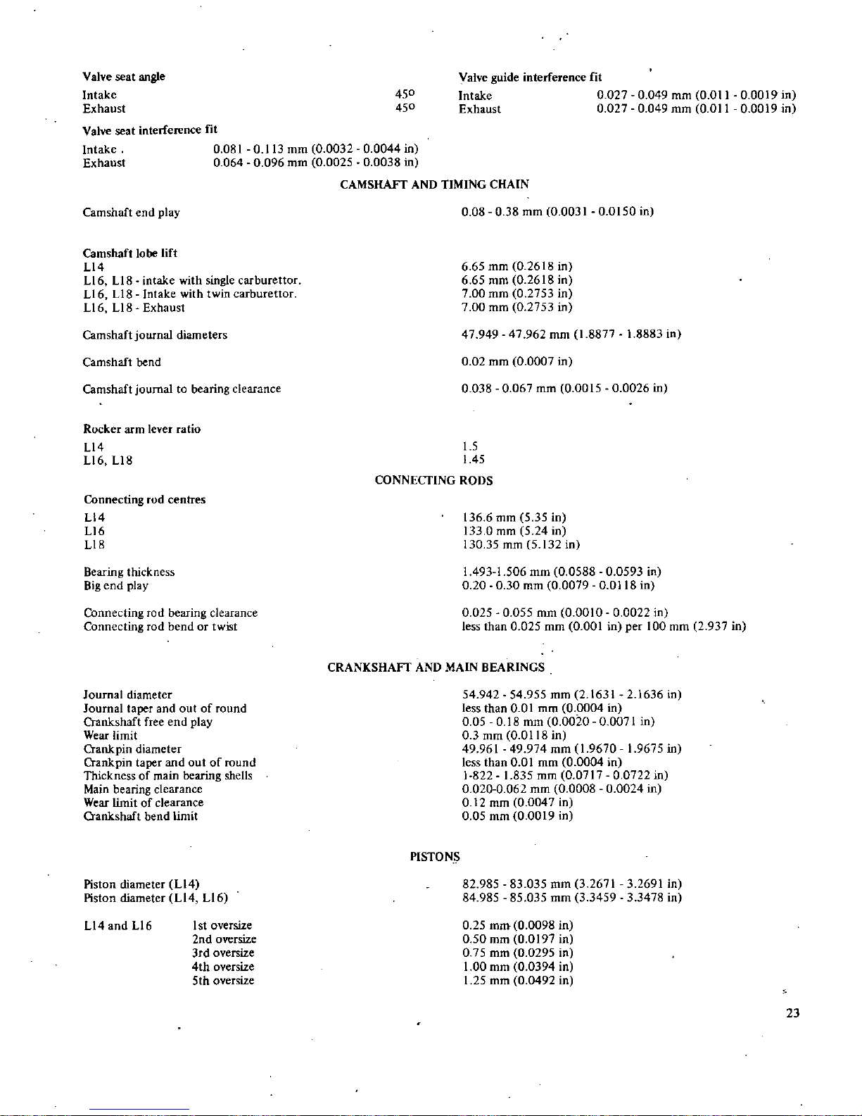
Valve
seat
angle
Intake
Exhaust
Valve
seat
interference
fit
450
450
Valve
guide
interference
fit
Intake
0
0270049
mm
0
01100019
in
Exhaust
0
0270049
mm
0
01100019
in
Intake
Exhaust
0
0810113
mm
0
003200044
in
0
0640096
mm
0
002500038
in
CAMSHAFT
AND
TIMING
CHAIN
Camshaft
end
play
0 08038
mm
0
0031
0
0150
in
Camshaft
lobe
lift
L14
Ll6
LIB
intake
with
single
carburettor
Ll6
LIB
Intake
with
twin
carburettor
L16
L18
Exhaust
6
65
mm
0
2618
in
6
65
mm
0
2618
in
7
00
mm
0
2753
in
7
00
mm
0
2753
in
47
949
47
962
mm
1
8877
1
8883
in
0 02
mm
0
0007
in
0
0380067
mm
0
0015
0
0026
in
Camshaft
journal
diameters
Camshaft
bend
Camshaft
journaltobearing
clearance
Rocker
arm
lever
ratio
L14
L16
L18
15
1
45
CONNECTING
RODS
Connecting
rod
centres
L14
L16
L18
136
6
mm
535In
133
0
mm
5
24
in
130
35
mm
5
132
in
I
4931506
mm
0
0588
0
0593
in
0 20030
mm
0
0079
0
0118
in
0
0250055
mm
0
0010
0
0022
in
less
than0025
mm
0
001
in
per
100
mm
2
937
in
Bearing
thickness
Big
end
play
Connecting
ro
d
bearing
clearance
Connecting
rod
bendortwist
CRANKSHAFI
AND
MAIN
BEARINGS
Journal
diameter
Journal
taper
and
out
of
round
Crankshaft
free end
play
Wear
limit
Crank
pin
diameter
Crankpin
taper
and
out
of
round
Thickness
of
main
bearing
shells
Main
bearing
clearance
Wear
limitofclearance
Crankshaft
bend
limit
54
942
54
955
mm
2
163121636
in
less
than
0 0
I
mm
0
0004
in
0 05018
mm
0
0020
0
0071
in
0
3
mm
0
0118
in
49
961
49
974
mm
1
967019675
in
less
than001
mm
0
0004
in
1
8221835
mm
0
0717
0
0722
in
0
0200062
mm
0
0008
0
0024
in
0
12
mm
0
0047
in
0 05
mm
0
0019
in
PISTONS
Piston
diameter
L14
Piston
diameter
L14 L16
82
985
83
035
mm
3
2671
32691 in
84
985
85
035
mm
3
345933478
in
LI4andLl6
1stoversize
2nd
oversize
3rd
oversize
4th
oversize
5th
oversize
0
25
mm
0
0098
in
0 50
mm
0
0197
in
0
75
mm
0
0295
in
1
00
mm
0
0394
in
1
25
mm
0
0492
in
23
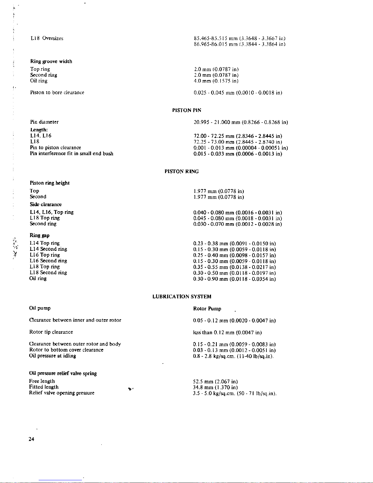
liB
Oversizes
Ring
groove
width
Top
ring
Second
ring
Oil
ring
Pistontobore
clearanl
e
Pin
diameter
I
ength
Ll4
Ll6
Ll8
Pin
to
piston
clearance
Pin
interference
fitinsmall
end
bush
Piston
ring
height
Top
Second
Side
clearance
Ll4 Ll6
Top
ring
LI8
Top
ring
Second
ring
Ring
gap
U4
Top
ring
U4
Second
ring
Ll6
Top
ring
L16Second
ring
U8
Top
ring
U8
Second
ring
Oil
ring
Oil
pump
Oearance
between
inner
and
outer
rotor
Rotor
tip
clearance
Oearance
between
outer
rotor
and
body
Rotor
to
bottom
cover
clearance
Oil
pressure
at
idling
Oil
pressure
relief
valve
spring
Free
length
Fitted
length
Relief
valve
opening
pressure
24
85465485
515
mm
3
648 667
ill
86
06586015
mm
13
3844
33864 in
0
mm
CO
0787
in
0
mm
0
0787
in
4
0
mm
01qc
in
0
0250045
mm
0
0010
0
0018
in
PISTON
PIN
20
995
1
000
mm
0
8266
0
8168
in
72
00
72 25
0
001
0
Dl5
72 25
mm
2
834628445
in
73 00
mm
2
844528740
in
0
013
mm
0
00004
0
00051
in
0
033
mm
0
000600013
in
PISTON
RING
1
977
mm
0
0778
in
1
977
mm
0
0778
in
0
0400080
mm
0
001600031
in
0
0450080
mm
0
001800031
in
0
0300070
mm
0
0012
0
0028
in
0
23
0 38
mm
0
009100150
in
0
15030
mm
0
005900118
in
0
25040
mm
0
009800157
in
0
15
0 30
mm
0
005900118
in
0
35 0
55
mm
0
013800217
in
0
30 0
50mm
0
011800197
in
0
30 0
90
mm
0
011800354
in
LUBRICATION
SYSTEM
Rotor
Pump
0 05 0
12
mm
0
0020
0
0047
in
less
than012
mm
0
0047
in
0150
21
mm
0
005900083
in
0
03 0
13
mm
0
001200051
in
0 8 2 8
kg
sq
cm
1140
Ib
sq
ln
52
5
mm
2
067
in
34
8
mm
1
370
in
3 5 5
0
kg
sq
cm
50
71
Ib
sq
ln
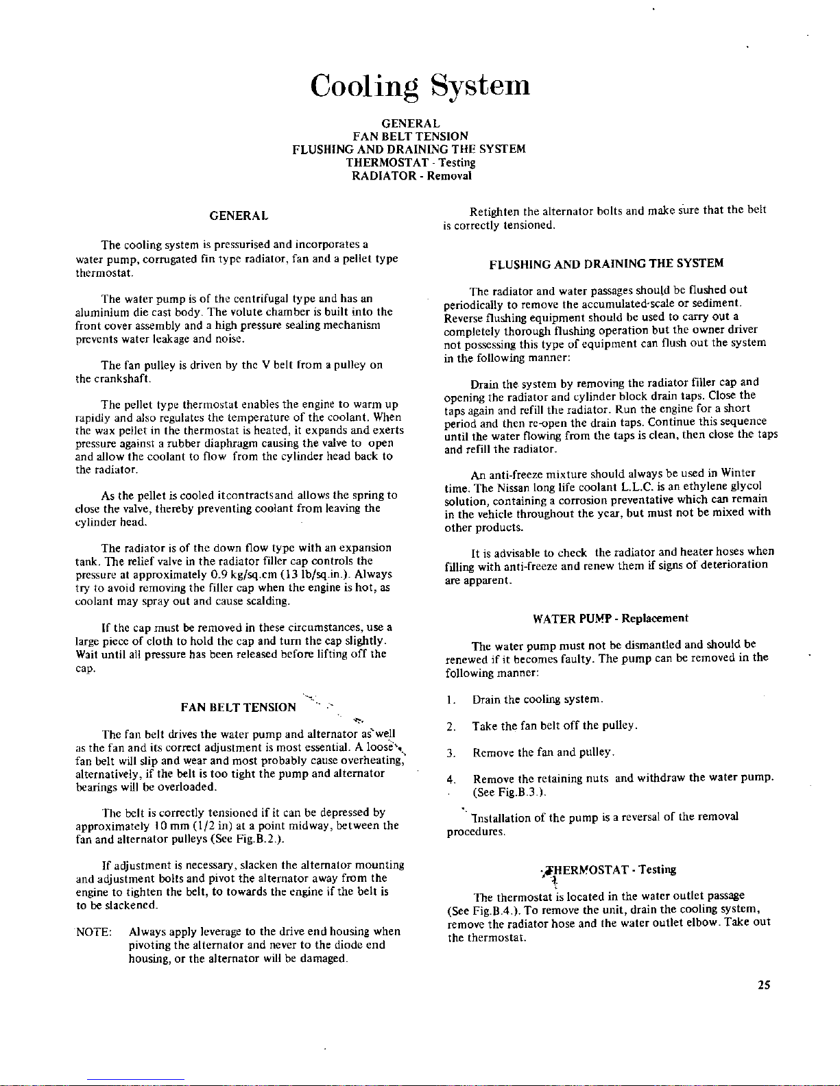
CoolIng
System
GENERAL
FAN
BELT
TENSION
FLUSHING
AND
DRAINING
THE
SYSTEM
THERMOSTAT
Testing
RADlA
TOR
Removal
GENERAL
The
cooling
system
is
pressurised
and
incorporates
a
water
pump
corrugated
fin
type
radiator
fan
and
a
pellet
type
thermostat
The
water
pump
isofthe
centrifugal
type
and
has
an
aluminium
die
cast
body
The
volute
chamberisbuilt
into
the
front
cover
assembly
and
a
high
pressure
sealing
mechanism
prevents
water
leakage
and
noise
The
fan
pulley
is
driven
by
the
V
belt
from
a
pulley
on
the
crankshaft
he
pellct
type
thermostat
enables
the
engine
to
warm
up
rapidlY
and
also
regulates
the
temperature
of
the
coolant
When
the
wax
pellet
in
the
thermostat
is
heated
it
expands
and
exerts
pressure
against
a
rubber
diaphragm
causing
the
valve
to
open
and
allow
the
coolant
to
flow
from
the
cylinder
head
back
to
the
radiator
As
the
pellet
is
cooled
itcontractsand
allows
the
spring
to
close
the
valve
thereby
preventing
coolant
from
leaving
the
cylinder
head
The
rad
ator
is
of
the
down
flow
type
with
an
expansion
tank
The
relIef
valveinthe
radiator
filler
cap
controls
the
pressure
at
approximately
0
9
kg
sq
cm
l3Ib
sqinAlways
try
to
avoid
removing
the
filler
cap
when
the
engine
is
hot as
coolant
may
spray
out
and
cause
scalding
If
the
cap
must
be
removed
in
these
circumstances
use
a
lar
e
pic
c
of
cloth to
hold
the
cap
and
turn
the cap
sli
htlY
Walt
until
all
pressure
has
been
released
before
lifting
off
the
cap
FANBELT
TENSION
The
fan
belt
drives
the
water
pump
and
alternator
as
well
as
the
fan
and
its
correct
adjustment
is
most
essential
A
loose
fan
belt
will
sl
ip
and
Y
e
r
and
most
probably
cause
overheating
alternatively
If
the
belt
IS
too
tight
the
pump
and
alternator
bearings
willbeoverloaded
The
belt
is
correctly
tensioned
if
it
can
be
depressed
by
approximately
10
mm
1
2
in at a
point
midway
between
the
fan
and
alternator
pulleys
See
Fig
R2
If
adjustment
is
neces
ary
slacken
the
alternator
mounting
and
adjustment
bolts
and
pivot
the
alternator
away
from
the
enginetotighten
the
belt
to
towards
the
engine
if
the
belt
is
to
be
slackened
NOTE
Always apply
leverage
to
the
drive end
housing
when
pivoting
the
alternator
and
never
to
the
diode
end
housing
or
the
alternator
will
be
damaged
Retighten
the
alternator
bolts
and
make
SUfe
that
the
belt
is
correctly
tensioned
FLUSHING
AND
DRAINING
THE
SYSTEM
The
radiator
and
water
passages
should
be
flushed
out
periodically
to
remove
the
accumulated
scaleorsediment
Reverse
flushing
equipment
should
be
used
to
carry
out
a
completely
thorough
flushing operation
but
the
owner
drivef
not
possessing
this
type
of
equipment
can
flush
out
the
system
in
the
following
manner
Drain
the
system
by
removing
the
radiator
filler
cap
and
opening
the
radiator
and
cylinder
block
drain
taps
Close
the
taps
again
and
refill
the
radiator
Run
the
engine
foraShOft
period
and
then
rc
open
the
drain
taps
Continue
this
sequence
until
the
water
flowing
from
the
taps
is
clean
then
close
the
taps
and
refill
the
radiator
An
anti
freeze
mixture
should
always
be
used
in
Winter
time
The
Niss3n
long
life
coolant
LL
c
is
an
ethylene
glycol
solution
containing
a
corrosion
preventative
which
can
remain
in
the
vehicle
throughout
the
year
but
must
not
be
mixed
with
other
products
Itisadvisable
to
check
the
radiator
and
heater
hoses
when
filling
with
anti
freeze
and
renew
them
if
signs
of
deterioration
are
apparent
WATER
PUMP
Replacement
The
water pump
must
not
be
dismantled
and
should
be
renewed
ifitbecomes
faulty
The
pump
can
be
removed
in
the
following
manner
Drain
the
cooling
system
2
Take
the fan
belt
off
the
pulley
3
Remove
the
fan
and
pulley
4
Remove
the
retaining
nuts
and
withdraw
the
water
pump
See
Fig
B 3
lnstallation
of
the
pump
isareversalofthe
removal
procedures
rERMOST
ATTesting
The
thermostat
is
located
in
the
water
outlet
passage
See
Fig
B
4
To
remove
the
unit
drain
the
cooling
system
remove
the
radiator
hose
and
the
water
outlet
elbow
Take
out
the
thermostat
25
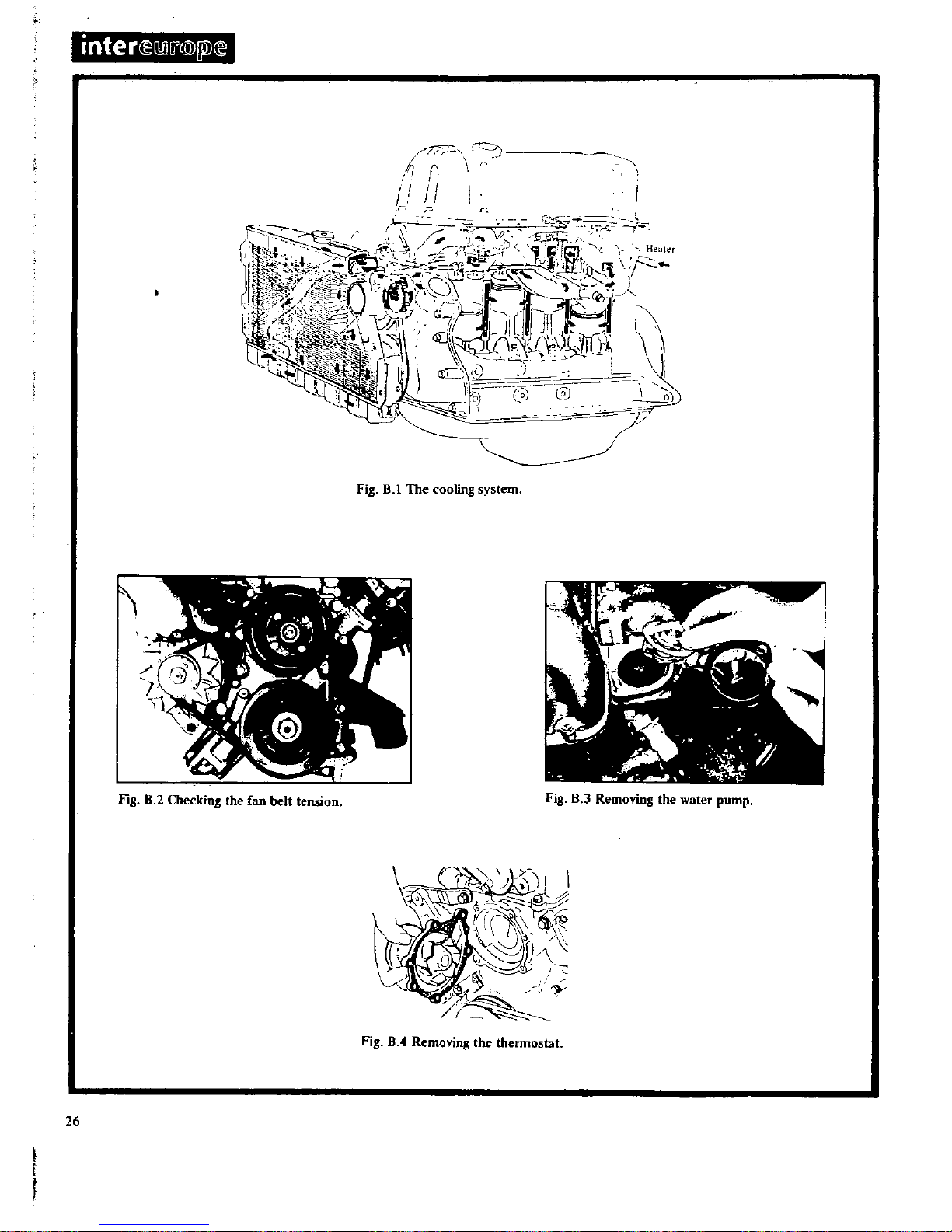
inter
illIl
@
Pl
i
i
n
i
II
L
Vi
It
q
n
lli
J
j
tr
rl
t
lli
3
t
11
1
i
l
Wt
r
till
I
cj
L
f0
co
7
Fig
B
l
The
cooling
system
Fig
8
2
Olecking
the
fan
belt
tension
Fig
B
3
Removing
the
water
pump
Fig
B
4
Removing
the
thermostat
26
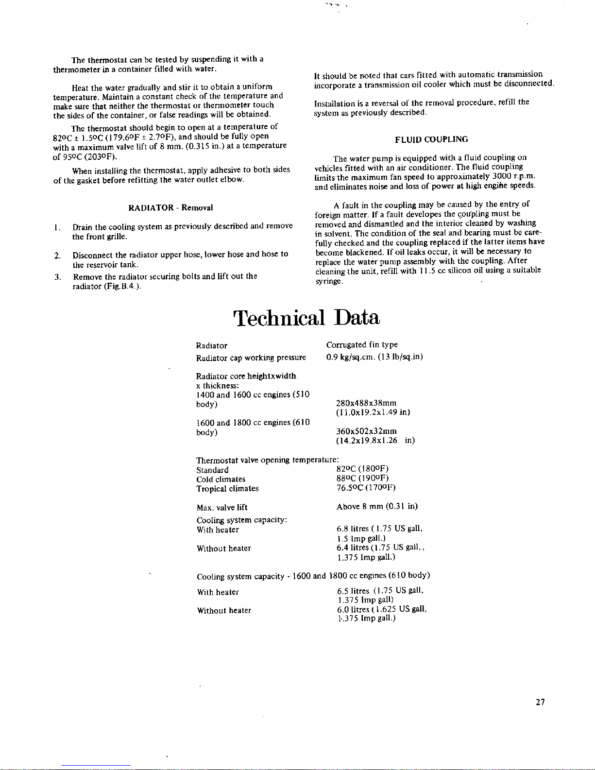
The
thermostat
can
be
tested
by suspending
it
with a
thermometer
in a
container
ftlled
with
water
Heat
the
water
gradually
and
stir
ittoobtainauniform
temperature
Maintain
a
constant
checkofthe
temperature
and
make
sure
that
neither
the
thermostat
or
thermometer
touch
the
sidesofthe
container
or
false
readings
willbeobtained
The
thermostat
should
begin
to
open
at a
temperature
of
820C
1
50C
179
60F
2
70Fj
and
should
be
fully
open
with a
maximum
valve
liftof8
mm
0
315
in at a
temperature
of
950C
2030F
When
installing
the
thermostat
apply
adhesive
to
both
sides
of
the
gasket
before
refitting
the
water
outlet
elbow
RADIATOR
Removal
Drain
the
cooling
systemaspreviously
described
and
remove
the
front
grille
2
Disconnect
the
radiator
upper
hose
lower
hose
and
hose
to
the
reservoir
tank
3
Remove
the
radiator
securing
bolts
and
lift
out
the
radiator
Fig
B
4
It
should
be
noted
that
cars
fitted
with
automatic
transmission
incorporate
a
transmission
oil
cooler
which
must
be
disconnected
Installation
isareversalofthe
removal
procedure
refill
the
system
as
previously
described
FLUID
COUPLING
The
water
pump
is
equipped
withafluid
coupling
on
vehicles
fitted
with
an
air
conditioner
The
fluid
coupling
Limits
the
maximum
fan
speedtoapproximately
3000
rpro
and
eliminates
noise
and
loss
of
power
at
high
engine
speeds
A
faultinthe
coupling
may
be
causedbythe
entry
of
foreign
matter
Ifafault
developes
the
oupling
must
be
removed
and
dismantled
and
the
interior
cleaned
by
washing
in
solvent
The
condition
of
the
seal
and
bearing
must
be
care
fully
checked
and
the
coupling
replaced
if
the
latter
items
have
become
blackened
If
oil
leaks
occur
it
will
be
necessary
to
replace
the
water
pump
assembly
with
the
coupling
After
cleaning
the
unit
refill
with
11 5ccsilicon
oil
using
a
suitable
syringe
TechnIcal
Data
Radiator
Radiator
cap
working
pressure
Radiator
core
heightxwidth
x
thickness
1400
and
1600
cc
engines
510
body
1600 and
1800
cc
engines
610
body
Corrugated
fin
type
0
9
kg
sq
cm
13Ib
sq
in
280x488x38mm
I
LOx192x149
in
360x502x32mm
l4
2x19
8x1
26
in
Thermostat
valve
opening
temperature
Standard
B20ClBOOF
Cold
climates
880C
1900F
Tropical
climates
76
50C
l700F
Max
valve
lift
Cooling
system
capacity
With
heater
Without
heater
Cooling
system
capacity
With
heater
Above
8
mm
031in
6
8litres
175US
gall
15
Imp
gall
6
4litres
1
75
US
gall
1
375
Imp
gall
1600
and
1800
cc
engines
610
body
6
5litres
l
7
US
gall
1
375
Imp
gall
6 0
Iitres1625
US
gall
1
375
Imp
gall
Without
heater
27
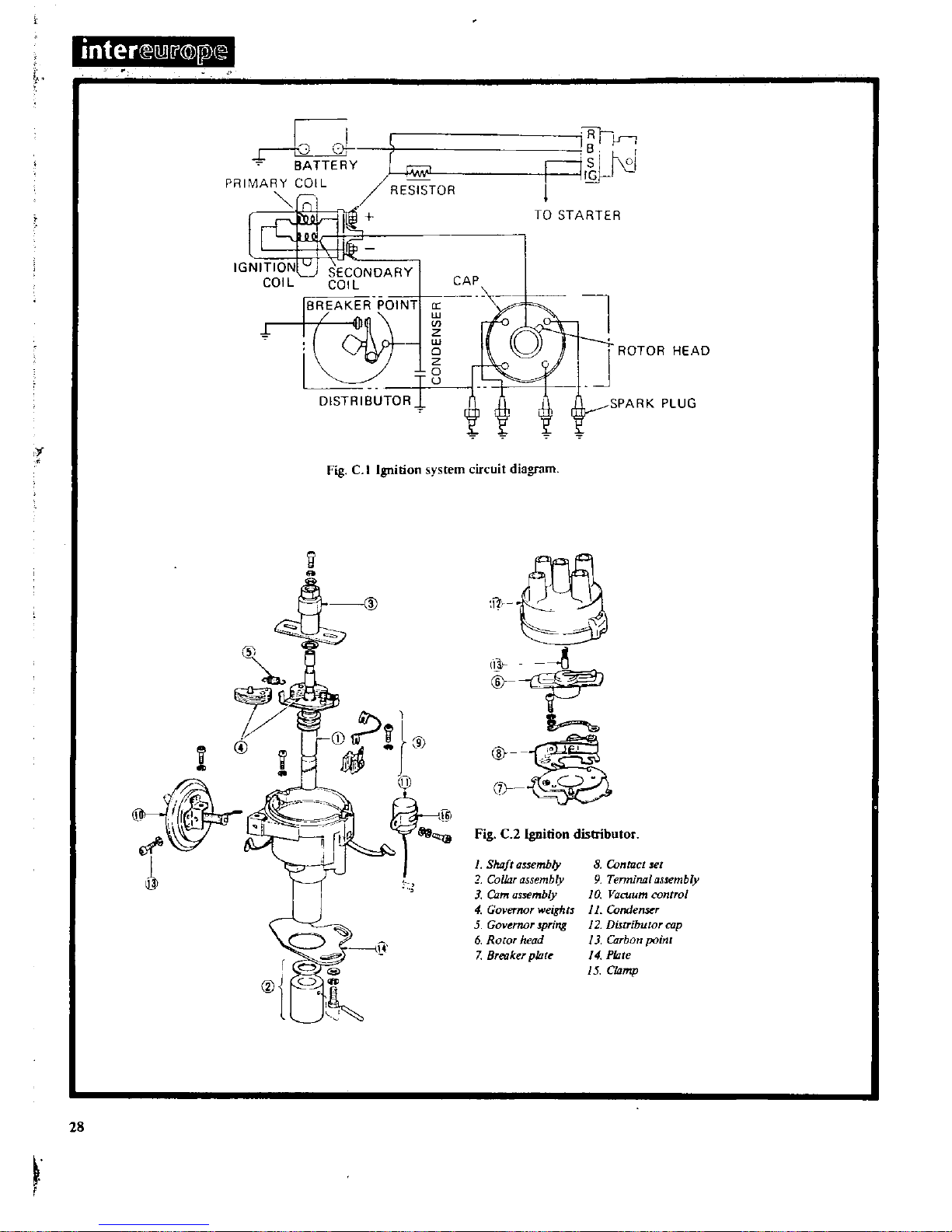
inter
lW
j
@lPX
TT
Y
Gw
PRIMARY
COIL
RESISTOR
I
I
l1@
l
I
IGNITION
U
SECONDARY
COIL COIL
IS
AK
R
POIN
i
1
1
DISTRISUTOR
I
1
J
ISI
V
nl
N
I
TO
STARTER
l
1
ROTOR
HEAD
r
SPARK
PLUG
Fig
C
t
Ignition
sys
em
circuit
diagram
i
II
@
1
1
@
J
i
9
28
l
I
i
1
I
I
@
@
G
N
7
FigC2lgnition
distributor
1
Shaft
assembly
2
Collar
assembly
3
Cam
assembly
4
Governor
weights
5
Governor
spring
6
Rowr
head
7
Breaker
plate
8
Contact
set
9
Tennirtal
assembly
10
Vacuum
control
J
1
Condenser
12
Distributor
cap
13
Carbon
point
14
Plate
15
CIilmp
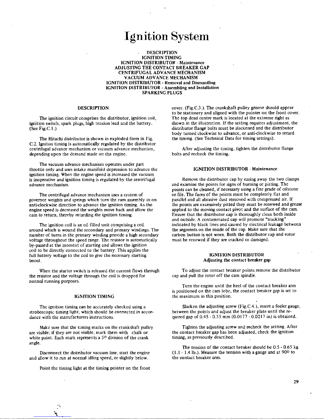
IgnItIon
System
DESCRII
TION
IGNITION
TIMING
IGNITION
DISTRIBUTOR
Maintenance
ADJUSTING THE
CONTACT
BREAKER
GAP
CENTRIFUGAL
ADVANCE
MECHANISM
VACUUM
ADVANCE
MECHANISM
IGNITION
DISTRIBUTOR
Removal
and
Dismantling
IGNITION
DISTRIBUTOR
Assembling
and
Installation
SPARKING
PLUGS
DESCRII
TION
The
ignition
circuit
comprises
the
distributor
ignition
coil
ignition
switch
spark
plugs
high
tension
lead
and
the
battery
See
Fig
C
1
The
Hitachi
distributor
is
shown
in
exploded
form
in
Fig
C
2
19niton
timing
is
automatically
regulated
by
the
distributor
centrifugal
advance
mechanism
or
vacuum
advance
mechanism
depending
upon
the
demand
made
on
the
engine
The
vacuum
advance
mechanism
operates
under part
throttle
only
and
uses
intake
manifold
depression
to
advance
the
ignition
timing
When
the
engine
speed
is
increased
the
vacuum
is
inoperative
and
ignition timingisregulated
by
the
centrifugal
advance
mechanism
The
centrifugal
advance
mechanism
uses
a
system
of
governor
weights
and
springs
which
turn
the
carn
assembly
in
on
anti
clockwise
direction
to
advance
the
ignition
timing
As
the
engine
speed
is
decreased
the
weights
move
back
and
allow
the
cam
to
return
thereby
retarding
the
ignition timing
The
ignition
coil
isanoil
filled
unit
comprising
a
coil
around
whichiswound
the
secondary
and
primary
windings
The
number of
turns
in
the
primary winding
provideahigh
secondary
voltage
throughout
the
speed
range
The
resistor
is automatically
by
passed
at
the
moment
of
starting
and
allows
the
ignition
coiltobe
directly
connected
to
the
battery
This
applies
the
full
battery
voltage
to
the
coil
to
give
the
necessary
staTting
boost
When
the
starter
switchisreleased
the
current
flows
through
the
resistor
and
the
voltage
through
the
coil
is
dropped
for
normal
running
purposes
IGNITION
TIMING
The
ignition timing
can
be
accurately
checked
using
a
stroboscopic
timing
light
which
should
be
connected
in
accor
dance
with
the
manufacturers
instructions
Make
sure
that
the
timing
marks
on
the
crankshaft
pulley
are
visible
if
they
are not
visible
mark
them
with
chalk
or
white
paint
Each
mark
represents
a
50
division
of
the
crank
angle
Disconnect
the
distributor
vacuum
line
start
the
engine
and
allow
it
to
run
at
normal
idling
speedorslightly
below
Point
the
timing
light
at
the
timing
pointer
on
the
front
cover
Fig
C3The
crankshaft
pulley
groove
should
appear
to
be
stationery
and
aligned
with
the
pointer
on
the
front
cover
The
top
dead
centre
markislocated
at
the
extreme
right
as
showninthe
illustration
If
the
setting
requires
adjustment
the
distributor
flange
bolts
must
be
slackened
and
the
distributor
body
turned
clockwise
to
advance
or
anti
clockwise
to
retard
the
timing
See
Technical
Data
for
timing
settings
After
adjusting
the
timing
tighten
the
distributor
flange
bolts
and
recheck
the
timing
IGNITION
DISTRIBUTOR
Maintenance
Remove
the
distributor
cap
by
easing
away
the
two
clamps
and
examine
the
points
for
signsofburningorpitting
The
points
can
be
cleaned
if
necessary
using
a
fine
grade
of
oilstone
or
file
The
faces
of
the
points
must
be
completely
flat
and
parallel
and
all
abrasive
dust
removed
with
compressed
air
If
the
points
are
excessively
pitted
they
must
be
renewed
and
grease
applied
to
the
moving
contact
pivot
and
the
surface
of
the
cam
Ensure
that
the
distributor
cap
is
thoroughly
clean
both
inside
and
outside
A
contaminated
cap
will
promote
tracking
indicated
by
black
lines
and
causedbyelectrical
leakage
between
the
segments
on
the
insideofthe
cap
Make
sure
that
the
carbon
button
is
not
worn
Both
the
distributor
cap
and
rotor
must
be
renewed
if
they
are
cracked
or
damaged
IGNITION
DISTRIBUTOR
Adjusting
the
contact
breaker
gap
To
adjust
the
contact
breaker
points
remove
the
distributor
cap
and
pull
the
rotor
off
the
cam
spindle
Turn
the
engine
until
the
heelofthe
contact
breaker
arm
is
positioned
on
the
cam
lobe
the
contact
breaker
gap
is
set
to
the
maximum
in
this
position
Slacken
the
adjusting
screw
Fig
CA
insertafeeler
gauge
between
the
points
and
adjust
the
breaker
plate
until
the
re
quired
gap
of045 0
55
mm
0
017700217
in
is
obtained
Tighten
the
adjusting
screw
and
recheck
the
setting
After
the
contact
breaker
gap
has
been
adjusted
check
the
ignition
timing
as
previously
described
The
tension
of
the
contact
breaker should
be 050 65
kg
I
II4
lb
Measure
the
tension
with
a
gauge
andat900
to
the
contact
breaker
arm
29
 Loading...