

Datsun BLUEBlRD P 410 Series Service Manual
I
1
A
rf
t
H
r
ff
A
l
1
1
4
1
ty
f
i
r
t
l
1
r
fr
l
J
t
r
cr
jo
r
11
t1f
r
i
I
h
r
SERVICE
MANUAL
J
DATSUN
4
4
MODEL
410
SERIES
I
f
NISSANI
1
NISSAN
MOTOR
CO
LTD
OTEMACHI
BLDG
OTEMACHI
CHIYODA
KU
TOKYO
JAPAN
CAIUS
ADDRtSS
NISMO
TOKYO
PHONES
211
5281
9
1
r
f
to
w
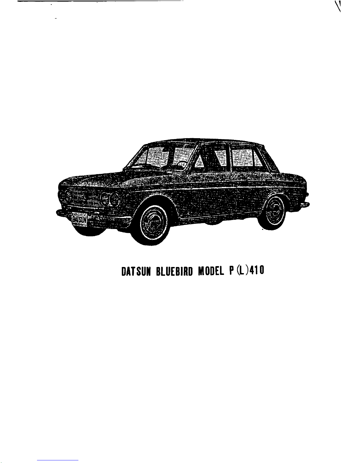
DlTSUI
BLUEBlRD
MODEL
P
L
41
0
INTRODUCTION
Thls
manual
has
been
comphes
for
purpose
of
asslstmg
DA
TSUN
dlstnbutors
and
dealers
for
effective
serVlCe
and
mamtenance
of
the
Model
P
L
410
Each
assembly
of
the
major
components
IS
descnbed
In
detaIl
In
addltlOn
com
prehenslve
mstructJOns
are
glven
for
complete
dl
manrlmg
assemblmg
and
mspectlOn
of
these
assembhes
It
IS
emphaslsed
that
only
genume
DA
TSUN
Spare
Parts
shuuld
be
used
as
replacements
j
i
129
152
153
158
i
159
166
169
1
l
I
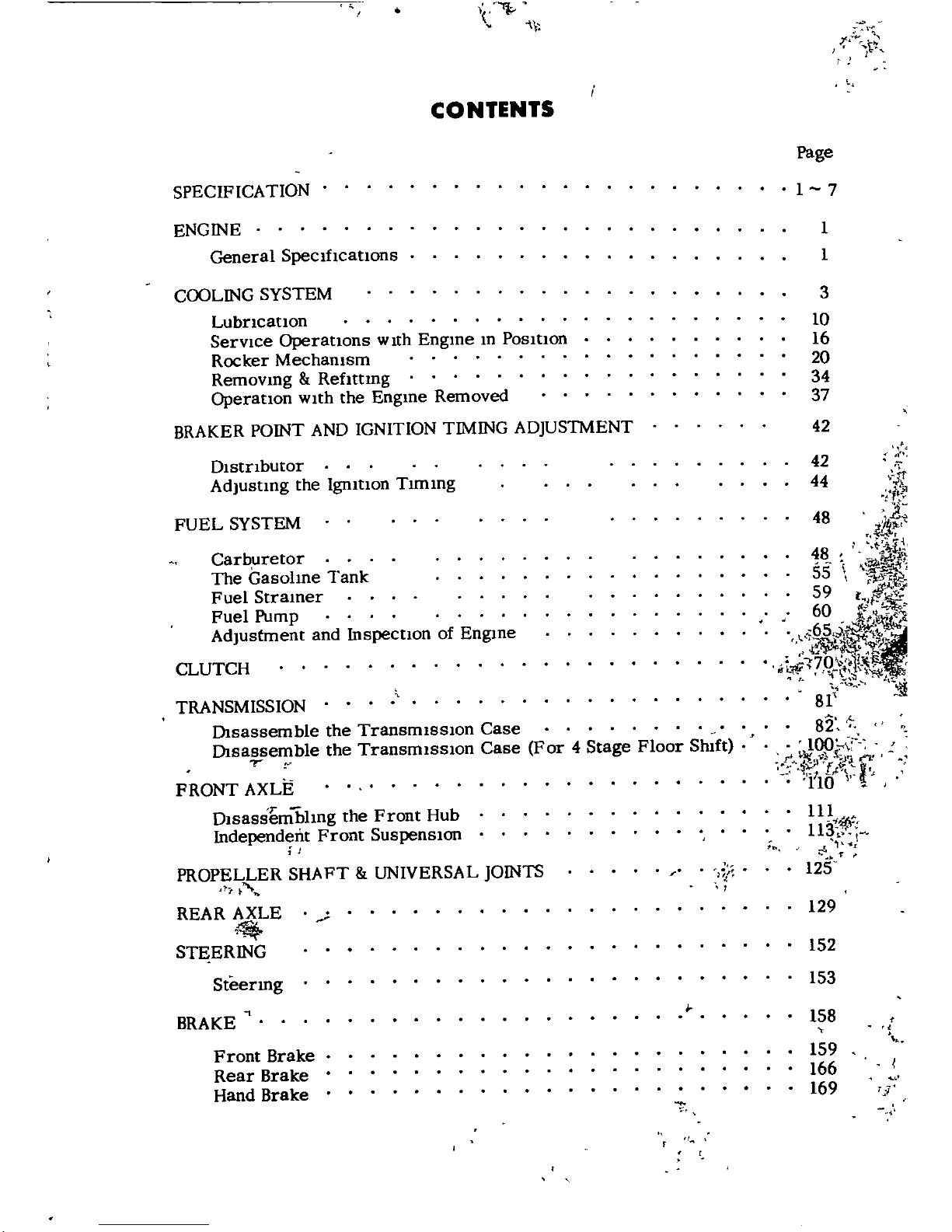
CONTENTS
SPECIFICA
TION
ENGINE
General
SpeclfIcatlons
COOLING
SYSTEM
LubrIcatlon
ServIce
OperatIons
WIth
Engme
m
PosltlOn
Rocker
Mechamsm
Removmg
Reflttmg
OperatlOn
WIth
the
Engme
Removed
BRAKER
POINT
AND
IGNITION
TIMING
ADJUSlMENT
DistrIbutor
AdJustmg
the
IgmtlOn
Tlmmg
FUEL
SYSTEM
Carburetor
The
Gasohne
Tank
Fuel
Stramer
Fuel
Pump
Adjustment
and
Inspectlon
of
Engme
CLUTCH
TRANSMISSION
DIsassemble the
TransmIssIon
Case
DIsassemble
the
TransmIssIon
Case
For
4
Stage
Floor
Slnft
r
FRONT
AXLE
1
Dlsassemblmg
the
Front
Hub
Independent
Front
SUSpenSIon
I
PROPELLER
SHAFT
UNIVERSAL
JOINTS
REAR
AXLE
STEERING
f
Steermg
BRAKE
Front
Brake
Rear
Brake
Hand
Brake
t
t
I
Page
l
7
1
1
3
10
16
20
34
37
42
42
44
48
r
Jf
1
r
i
ijf
1
48
55
59
60
65
4
r
i
170
1
t
h
8
I
lf
82
100
c
4b
l
1
t
no
ll
lq
i
l
I
J
125
ELECTRICAL
SYSTEM
Alternator
Generator
Regulator
14
Items
on
Handhng
Trouble
Shootmg
LIst
Starter
Motor
1
t
n
l
I
7
1
Page
172
l74
l76
l86
190
192
194
1
I
J
t
5
P
ICIFICA
ION
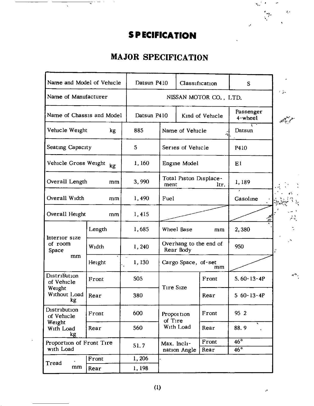
MAJOR
SPECIFICATION
Name
and
Model
of
VehIcle
Datsun
P410
ClassIfIcation
S
Name
of
Manufacturer
NISSAN
MOTOR
CO
LTD
Name
of
ChaSSIS
and
Model
Datsun
P410
Kmd
of
VehIcle
Passenger
4
wheel
VehIcle
Weight
kg
885
Name
of
VehIcle
Datsun
Seating
CapacIty
5
SerIes
of
VehIcle
P410
VehIcle
Gross
WeIght
kg
I
160
Engme
Model
EI
Overall
Length
mm
3
990
Total
PIston
Olsplace
I
189
ment
Itr
Overall
WIdth
mm
I
490
Fuel
Gasolme
Overall
HeIght
mm
I
415
Length
I
685
Wheel
Base
mm
2
380
InterIor
sIze
of
room
WIdth
I
240
Overhang
to
the
end
of
950
Space
Rear
Body
mm
HeIght
I
130
Cargo
Space
of
set
mm
DIstrIbutIOn
Front
505
Front
5
60
134P
of
VehIcle
WeIght
TIre
SIze
WIthout
Load
Rear
380
Rear
5
60
13
4P
kg
DIstrIbution
Front
600
PrOpOl
tlOn
Front
95
2
of
VehIcle
WeIght
of
TIre
WIth
Load
Rear
560
WIth
Load
Rear
88
9
kg
ProportIOn
of
Front
TIre
Max
Inch
Front
460
wIth
Load
51
7
nation
Angle
Rear
460
Front
I
206
Tread
mm
Rear
I
198
d
i
c
r
1

i
COMP
ARlBON
WITH
MAJOR
SPECIFICATION
OF
MODEL
P410
MODEL
ITEM
P410
F
VehIcle
Overall
Length
3
995
VehIcle
Overall
WIdth
1
490
VehIcle
Overall
HeIght
1
415
Intenor
SIze
of
Overall
Length
l
685
E
E
Cargo
Space
Overall
WIdth
1
240
Overall
HeIght
I
130
tI
Front
I
206
Z
Tread
a
Rear
1
198
CI
Z
Wheel
Base
2
380
w
Mm
Road
Clearance
175
Cl
Floor
HeIght
Overhang
to
the
Front
End
WIthout
Bumoer
605
Overhand
to
the
Rear
End
WIthout
950
Bumper
Frame
Overhand
to
the
Front
End
Frame
Overhang
to
the
Rear
End
Ww
Front
5
60
13
4P
t
r
N
Rear
60
13
4P
tI
VehIcle
WeIght
915
6
Seatmg
CapacIty
5
Max
Payload
VehIcle
Gross
WeIght
I
IOU
1
190
llIl
ol
O1stnbutlon
of
Front
505 525
Verncle
Wel
ht
Rear
380
390
WIthout
Loa
I
O1stnbutlon
of
Front
610 615
0
Verncle
WeIght
560 575
W
W
lth
Load
Rear
a
ChassIs
WeIght
DIstnbutlon
Front
Dlstnbutlon
Rear
HeIght
of
Gravlty
Center
mm
565
Max
Speed
krn
h
m
jh
128
80
mfh
r
w
18
au
Flat
Road
W2
Max
Load
krn
t
z
r
W
E
Grade
AbIlity
Sm
0
34
c
2
1
I
MODEL
P410
ITEM
r
w
Mm
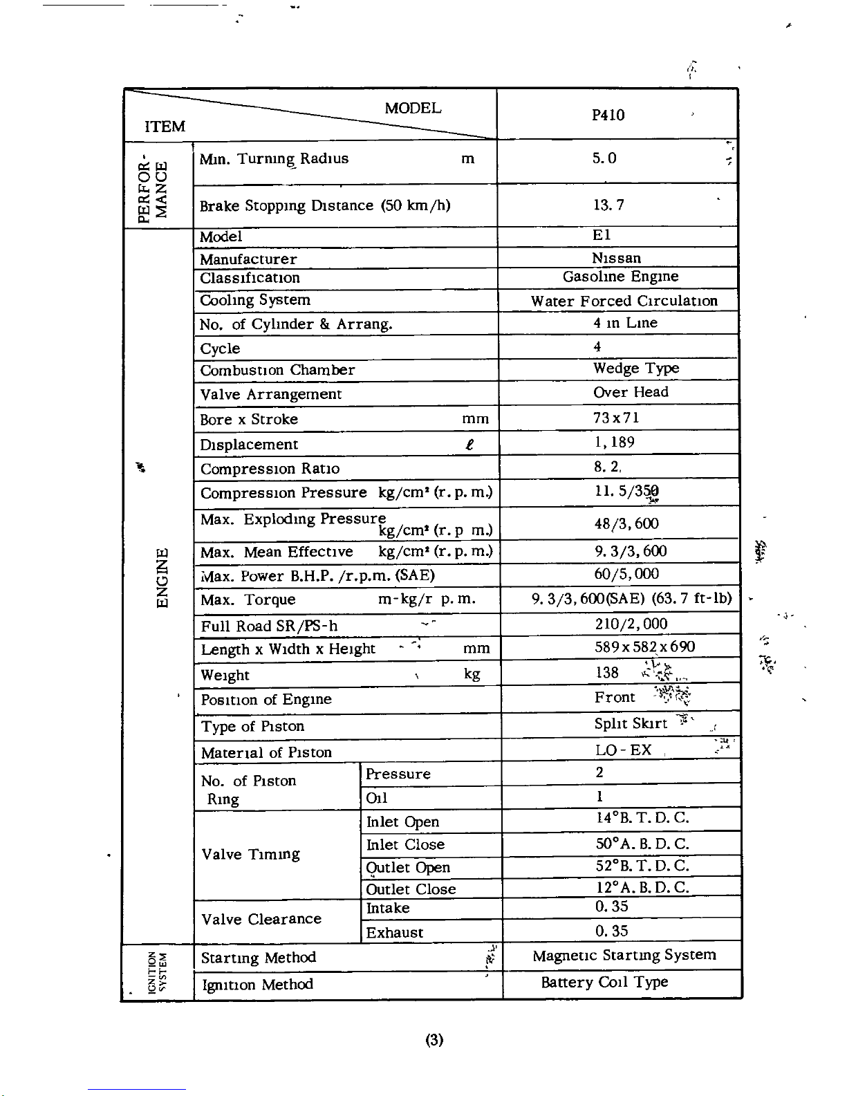
Turnm
RadIus
m
5
0
au
z
r
Brake
Stoppmg
DIstance
50
lcm
h
13
7
w
p
Model
El
Manufacturer
Nlssan
ClassIflCatlon
Gasohne
Engme
Coohng
System
Water
Forced
Clrculatlon
No
of
Cylmder
Arrang
4
m
Lme
Cycle
4
Combustlon
Chamber
Wedge
Type
Valve
Arrangement
Over
Head
Bore
x
Stroke
mm
73x71
DIsplacement
i
I
189
CompressIOn
Ratlo
8 2
CompressIOn
Pressure
kg
cm
r
p
m
11
5
358
Max
Explodmg
Pressure
483600
kg
cm
r
pm
W
Max
Mean
Effectlve
kg
cm
r
p
m
9 3 3
600
ii
lV1ax
Power
BHP
rpm
SAE
605000
0
Z
Max
Torque
m
kg
r
p
m
9 3 3
6oo
SAE
637ft
lb
w
Full
Road
SR
PS
h
210
2
000
Length
x
WIdth
x
HeIght
589x582x690
mm
Weight
kg
138
t
If
It
Position
of
Engme
Front
Type
of
PIston
SpIlt
Slart
Matenal
of
PIston
La
EX
No
of
PIston
Pressure
2
Rmg
all
I
Inlet
Open
140B
T
D C
Valve
Tlmmg
Inlet
Close
500
A
B
D C
Qutlet
Open
520B
T
D C
Outlet
Close
120
ABD C
Valve
Clearance
Intake
0
35
Exhaust
0
35
z
Startmg
Method
I
Magnetlc
Startmg
System
QUJ
itI
Battery
Coli
Type
z
Ignition
Method
2
y
0
3
i
MODEL
ITEM
P410
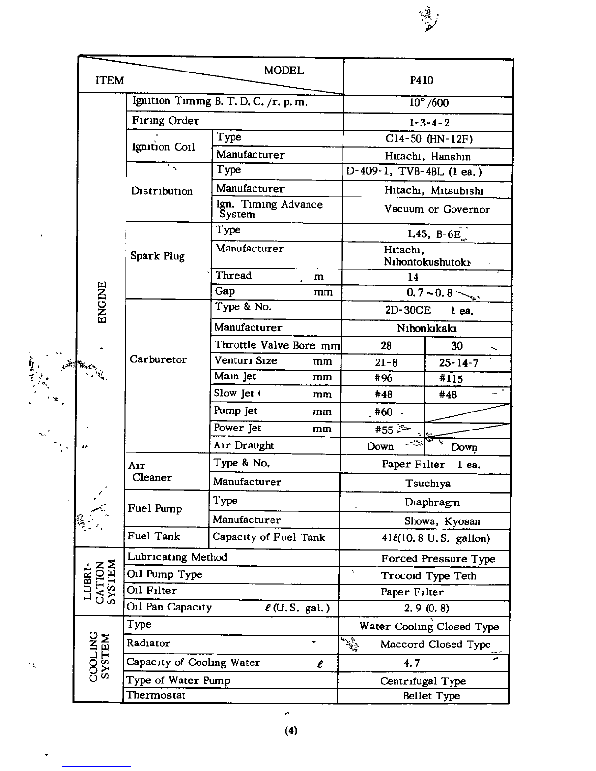
Igmtlon
Tlmmg
B
T
D C
r
p
m
100
600
FIring
Order
1
3 4 2
Type
C14
S0
HN
12F
IgllltIOn
Coll
Manufacturer
Hitachi
Hanshm
Type
0
409
I
TVB
4BL
l
ea
D1stnbutlOn
Manufacturer
Hltacln
MltsublsW
I
Tlmmg
Advance
Vacuum
or
Governor
ystem
Type
L45
B
6E
Manufacturer
Hitachi
Spark
Plug
Nlhontokushutob
Thread
J
m
14
W
Gap
O
7
0
8
Z
mm
0
Type
No 2D
30CE
lea
Z
W
Manufacturer
Nlhonlo
kakl
Throttle
Valve
Bore
mm
28
30
if
Carburetor
Ventun
SIze
mm
21
8
25
14
7
Malll
Jet
mm
96
115
Slow
Jet
1
mm
48
48
Pump
Jet
mm
60
Power
Jet
mm
55
p
AIr
Draught
Down
DoWV
l
AIr
Type
No
Paper
FIlter
1
ea
Cleaner
Manufacturer
Tsuchlya
A
Fuel
Pump
Type
DIaphragm
Manufacturer
Showa
Kyosan
Fuel
Tank
Capacity
of
Fuel
Tank
41t
lO8U
S
gallon
z
E
Lubncatmg
Method
Forced
Pressure
Type
OW
Chl
Pump
Type
TrocOld
Type
Teth
r
G
1
hJ
011
Filter
Paper
FIlter
J
UCIl
011
Pan
CapacIty
e
U
S
gal
2 9
0
8
Type
Water
Coohng
Closed
Type
O
E
Radiator
Maccord
Closed
Type
W
JI
4 7
8
CapaCIty
of
Coohng
Water
e
UCIl
Type
of
Water
Pump
Centnfugal
Type
Thermostat
Bellet
Type
II
4
MODEL
P4l0
ITEM
f
o
Type
of
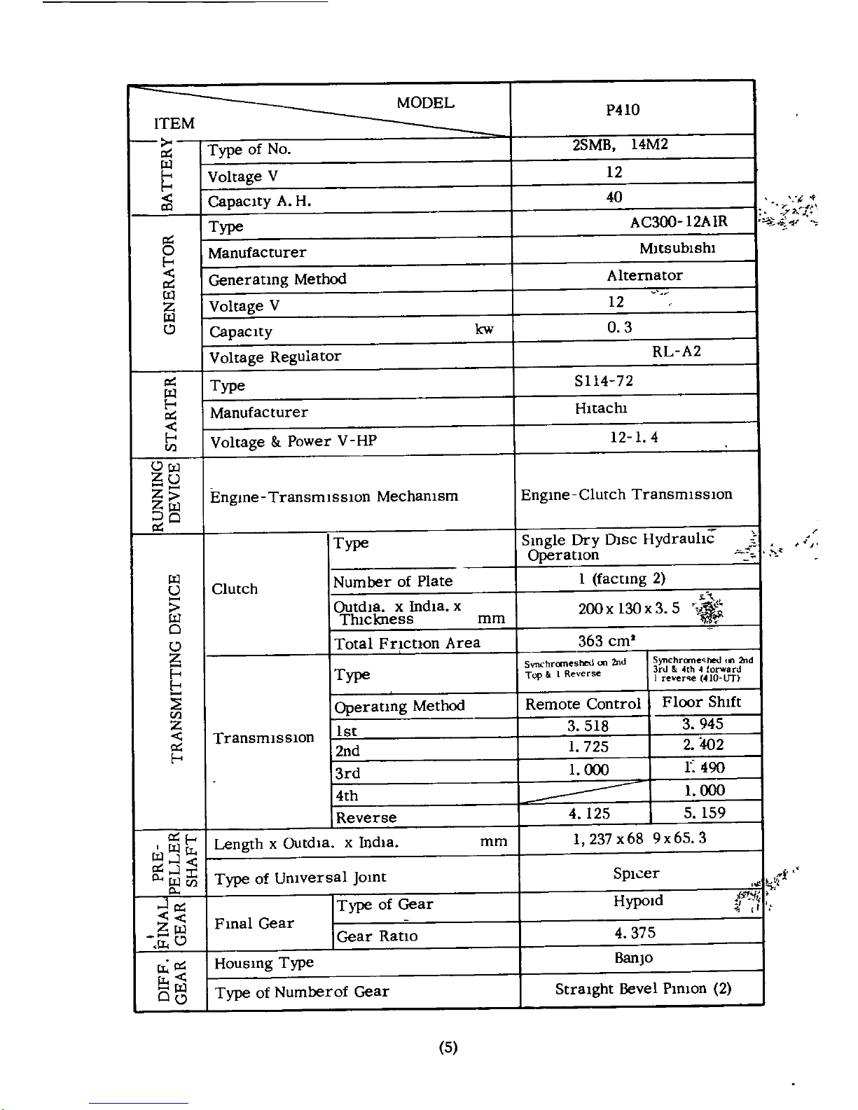
No
25MB
14M2
w
Voltage
V
12
CapacIty
A H
40
Type
AC300 12AIR
0
Manufacturer
MItsublShl
E
GeneratIng
Method
Alternator
w
Z
Voltage
V
12
w
0
CapacIty
kw
0
3
Voltage
Regulator
RL
A2
Type
5114
72
w
E
Manufacturer
HItachI
E
Voltage
Power
V
HP
l2
1
4
U
Ow
u
Z
Engme
TransmlsslOn
Mechamsm
EngIne
Clutch
TransmIssIon
z
w
O
Type
Smgle
Dry
Dlsc
Hydrauhc
o
Operatlon
W
Clutch
Number
of
Plate
I
factlng
2
U
l
Outd18
x
IndIa
x
200x130x3
5
w
ThIckness
mm
0
0
Total
Fnctlon
Area
363
em
Z
SynC
hrane
hedun2nd
Svnchromeshetl
on
2hd
E
Type
Top
I
Reverse
3n
4th
forward
E
I
reverqe
410
Un
Operatmg
Method
Remote
Control
Floor
ShIft
en
Z
1st
3
518
3
945
TransmlsslOn
2nd
1
725
2
402
E
3rd
1
000
r
490
4th
1
000
Reverse
4
125
5
159
E
Length
x
Outdla
x
IndIa
mm
1
237
x
68
9
x
65
3
wwrr
J
p
J
r
Type
of
Umversal
JOInt
SpIcer
WU
p
Type
of
Gear
HypOld
f1f
J
tf
1
I
z
Fmal
Gear
i
o
Gear
Ratio
4
375
rr
Housmg
Type
BanjO
rr
w
Type
of
Numberof
Gear
StraIght
Bevel
PInion
2
00
i
r
L
l
5
ITEM
MODEL
P410
O
E
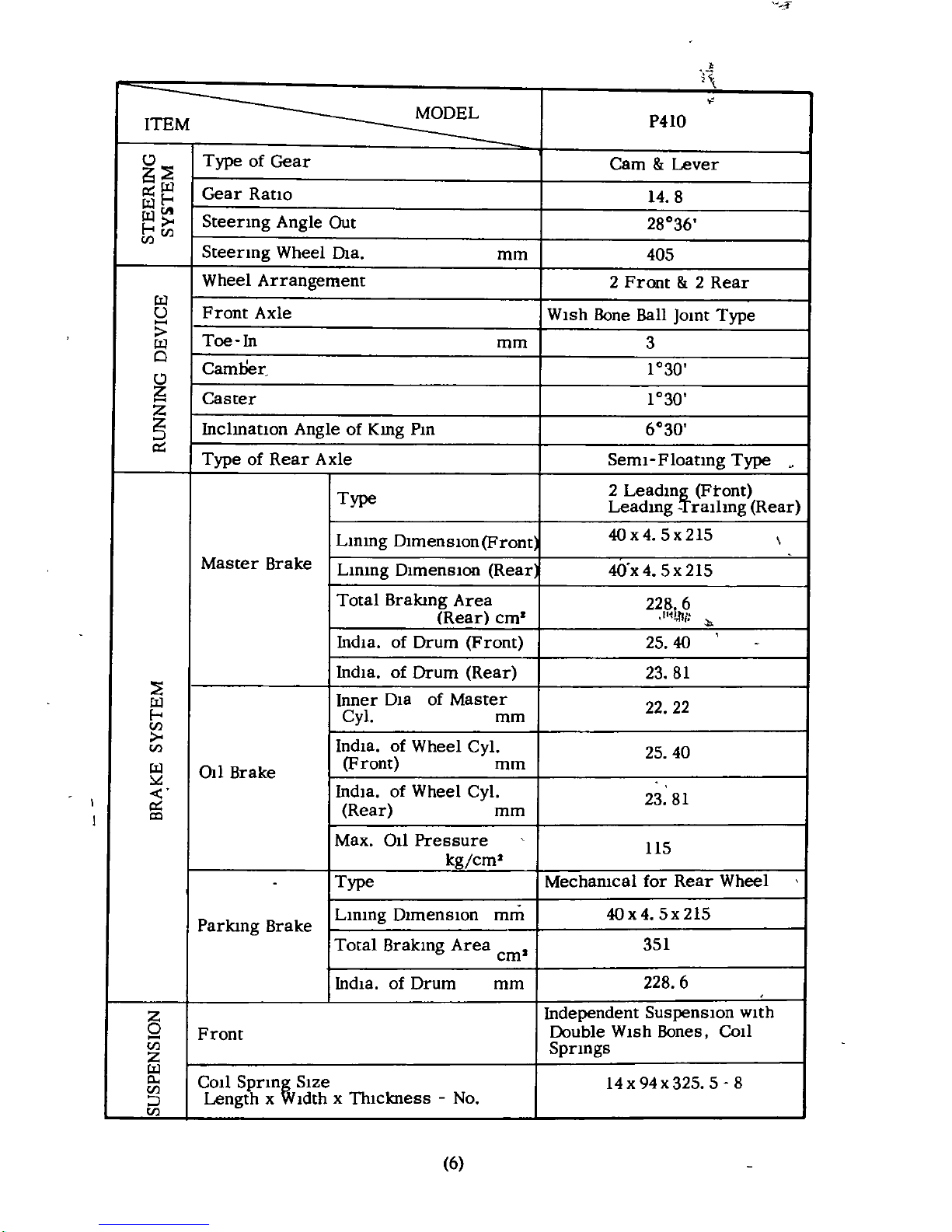
Type
of
Gear
Cam
Lever
W
Gear
Ratlo
1
1
14
8
WCJt
W
Steermg
Angle
Out
28036
1
CIl
CIl
Steering
Wheel
Ola
mm
405
Wheel
Arrangement
2
Front
2
Rear
W
U
Front
Axle
WIsh
Bone
Ball
Jomt
Type
Toe
In
3
W
mm
Cl
Camller
1030
0
Caster
1030
Z
5
Inclmatlon
Angle
of
Kmg
Pm
6030
I
Type
of
Rear
Axle
Seml
Floatmg
Type
Type
2
Leadm
Ftont
Leadmg
rallmg
Rear
Lmmg
DlmenslOn
Front
40x4 5x215
Master
Brake
Lmmg
DlmenslOn
Rear
40
x4
5x215
Total
Brakmg
Area
228
6
Rear
em
l
1hI
India
of
Drum
Front
25
40
IndIa
of
Drum
Rear
23
81
E
Inner
Dla
of
Master
W
22 22
1
Cyl
mm
CIl
India
of
Wheel
Cyl
CIl
25
40
W
011
Brake
Front
mm
India
of
Wheel
Cyl
23
81
I
Rear
mm
cc
Max
011
Pressure
US
kg
em
Type
Meehameal
for
Rear
Wheel
Parkmg
Brake
Lmmg
DlmenslOn
mm
4Ox4
5x215
Total
Brakmg
Area
351
em
India
of
Drum
mm
228
6
Z
Independent
SuspenslOn
WIth
0
Pront
Double
WIsh
Bones
COlI
CIl
Sprmgs
Z
Call
SprIn
Size
14
x
94x325
5 8
CIl
Length
x
IdthxTIuekness No
CIl
6
r
MODEL
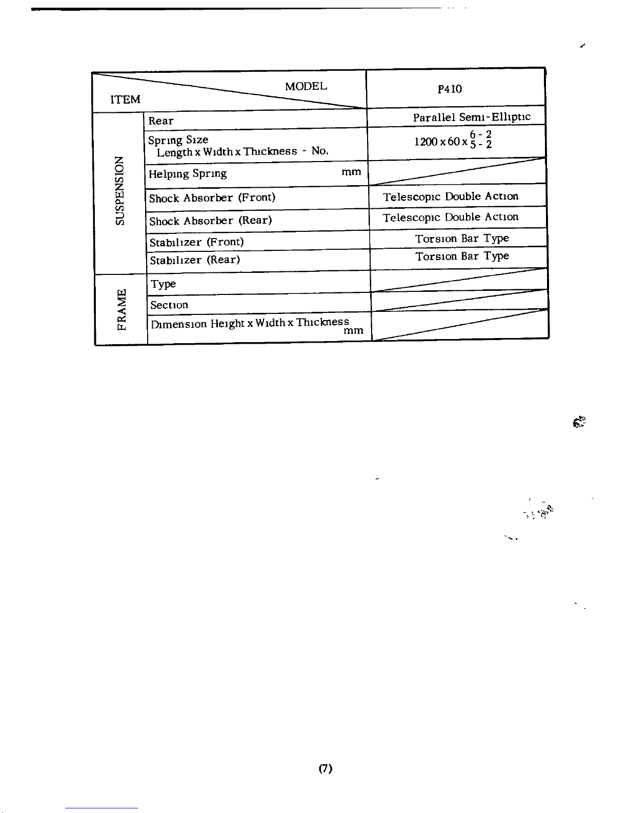
P410
ITEM
Rear
Parallel
Seml
Elhptlc
Sprmg
SIze
6 2
Length
x
WIdth
x
Thickness
No
1200x60x5
2
Z
Q
Helpmg
Spnng
mm
tIl
Z
W
Shock
Absorber
Front
Telescopic
Double
Action
p
tIl
J
Shock
Absorber
Rear
TelescopIc
Double
Action
tIl
Stabilizer
Front
TorSlOn
Bar
Type
Stabilizer
Rear
TorslOn
Bar
Type
W
Type
Section
O1menslOn
Height
x
Widthxl111ckness
iI
mm
7
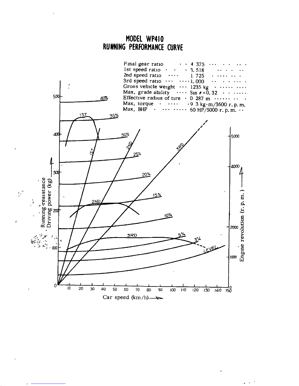
MODEl
WP4
10
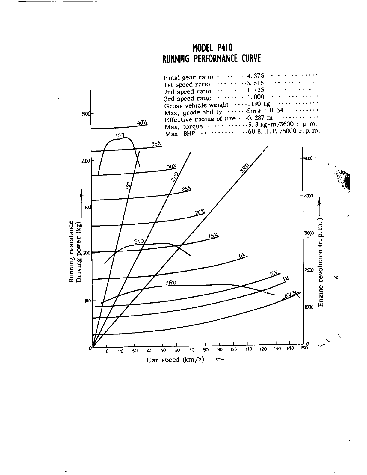
RUNNING
PERFORMANCE CURVE
500
40
F
mal
gear
ratio
1st
speed
ratIO
2nd
speed
ratIO
3rd
speed
ratio
Gross
vehicle
weight
Max
grade
abIlIty
Effective
radIUS
of
tire
Max
torque
Max
BHP
4
375
51S
1
725
1
000
1235
kg
Sm
6
0
32
o
287
m
9
3
kg
m
3600
r
p
m
60
HP
5000
r
p
m
5000
t
t
8
bO
t
J
co
U
l
aJ
E
00
ri
aJo
p
Cc
b
bllbll
t
t
t
t
l
0 0
fT
c
p
30 40
SO
60
70
80
QO
100
110
Car
speed
km
h
o
150
MODel P410
RUNNING
PERFORMANCE
CURVE
5lOO
J
I
1
CIl
CJbO
C
loi
6
I
3000
CIl
0
CJl
I
8
m
bObO
c
M
M
c
l
M
l
I
lX
O
3Ro
CIl
I
CIl
c
M
bO
U
J
500
Fmal
gear
rano
1st
speed
ratlO
2nd
speed
ratIo
3rd
speed
ratio
Gross
vehicle
weight
Max
grade
ablhty
Effective
radlUs
of
tIre
Max
torque
Max
BHP
40
35
4
375
3
518
1
725
1
000
1190
leg
Sm
0
34
0
287
m
9 3
kg
m
3600
r
p
m
60
BHP
5000
r
p
m
o
110
120
130 140
ISO
80
90
100
10
20
30
Car
speed
km
h
ENGINE
I
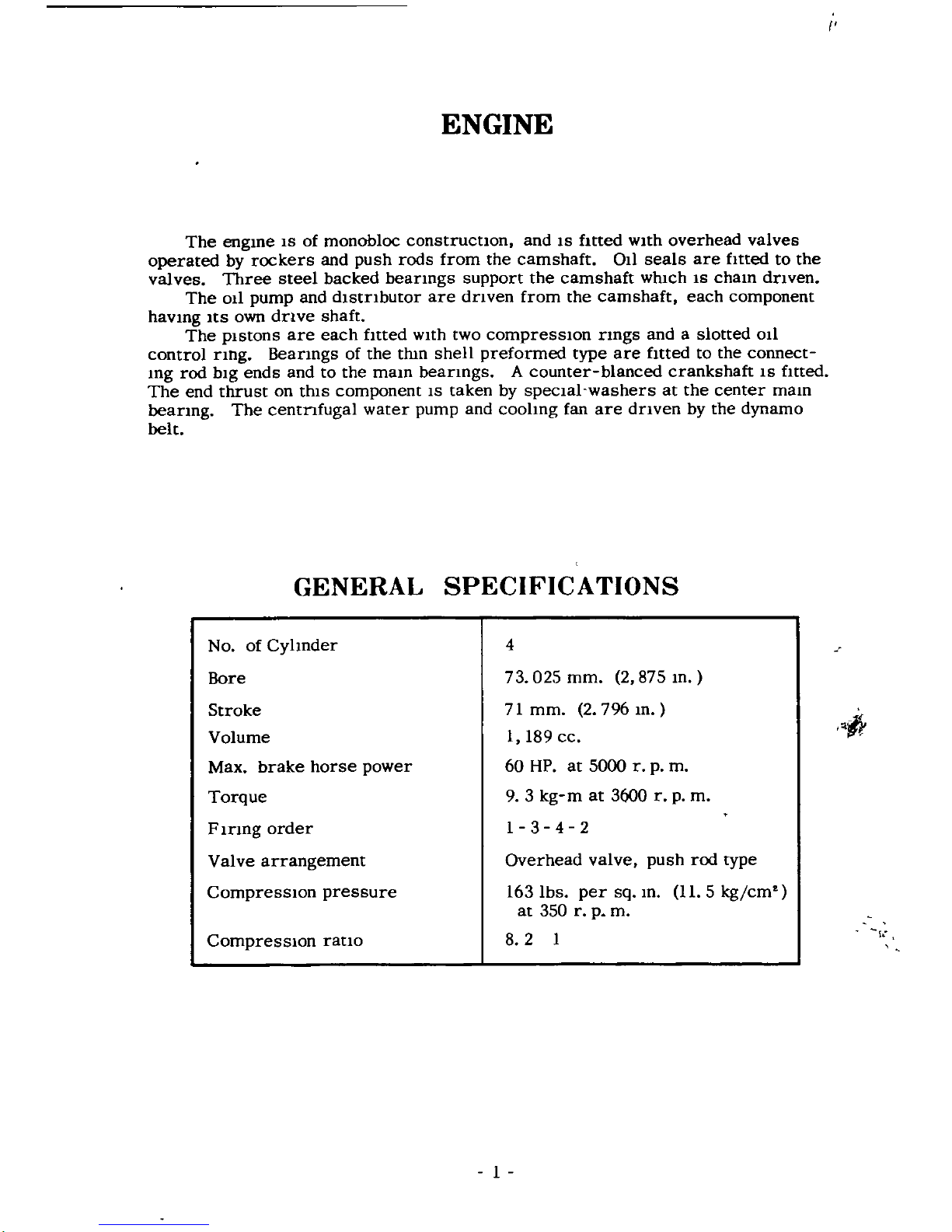
ENGINE
The
engme
IS
of
monobloc
construcnon
and
IS
fItted
wIth
overhead
valves
operated
by
rockers
and
push
rods
from
the
camshaft
011
seals
are
fitted
to
the
valves
Three
steel
backed
beanngs
support
the
camshaft
whIch
IS
cham
dnven
The OIl
pump
and
dlstnbutor
are
dnven
from
the
camshaft
each
component
havmg
ItS
own
dnve
shaft
The
pIstons
are
each
fItted
wIth
two
compresslOn
rmgs
andaslotted
OIl
control
nng
Beanngs
of
the
thm
shell
preformed
type
are
fItted
to
the
connect
mg
rod
bIg
ends
and
to
the
mam
beanngs
A
counter
blanced
crankshaft
IS
fItted
The
end
thrust
on
thIS
component
IS
taken
by
specIal
washers
at
the
center
mam
beanng
The
centnfugal
water
pump
and
coohng
fan
are
dnven
by
the
dynamo
belt
GENERAL
SPECIFICATIONS
No
of
Cyhnder
4
Bore
73
025
mm
2
875
m
Stroke
Volume
Max
brake
horse
power
Torque
F
Inng
order
Valve
arrangement
CompresslOn
pressure
71
mm
2
796
m
I
l89
cc
60
HP
at
5000
r
p
m
9
3
kg
m
at
3600
r
p
m
1
3 4 2
fr
Compression
rano
Overhead
valve
push
rod
type
163
Ibs
per
sq
m
11
5
kg
cm
at
350
r
p
m
8 2
I
1
ilft
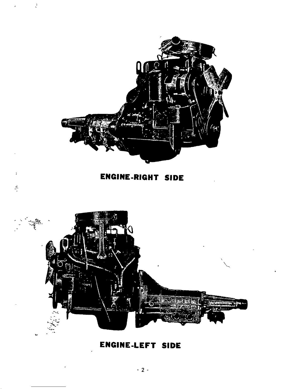
EMGIME
RIG
SlOE
t
l
x
JJcc
1
c
L
E7j
lt
c
li c
r
I
t
J
r
Ic
J
0
1
JF
I
l
1
r
Y
v
J
t
t
t
EMGIME
LEf
SlOE
2
vI
e
COOLING
SYSTEM
it
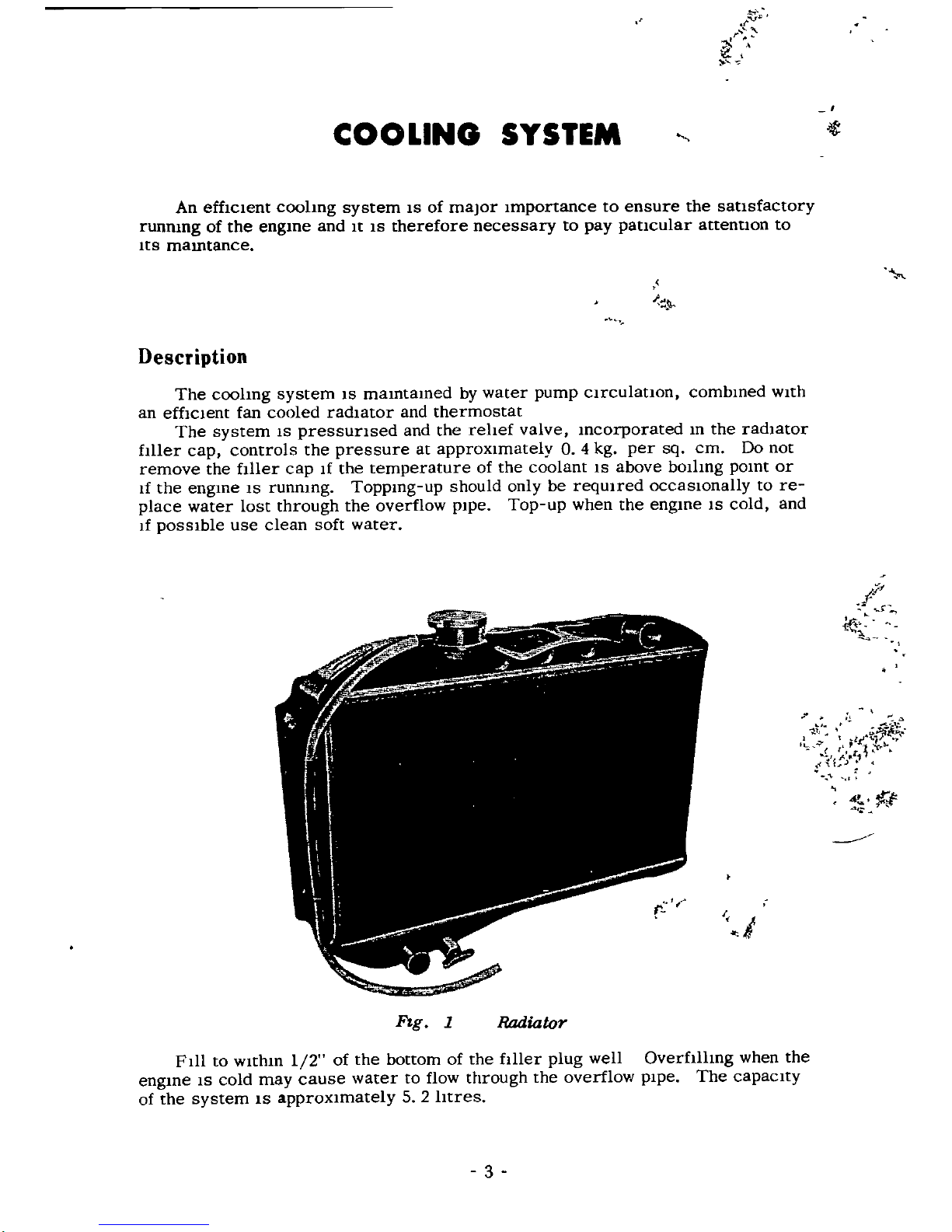
An effICIent
coohng
system
IS
of
major
Importance
to
ensure
the
sausfactory
runrung
of
the
engme
and
It
IS
therefore
necessary
to
pay
paucular
attentlOn
to
lts
mamtance
Description
The
coolmg
system
IS
mamtamed
by
water
pump
clrculatlon
combmed
wIth
an
efficient
fan
cooled
radIator
and
thermostat
The
system
IS
pressunsed
and
the
rehef
valve
mcorporated
m
the
radIator
fIller
cap
controls
the
pressure
at
approximately
0
4
kg
per
sq
cm
Do
not
remove
the
fIller
cap
If
the
temperature
of
the
coolant
IS
above
bOlhng
pomt
or
If
the
engme
IS
runmng
Toppmg
up
should
only
be
reqUIred
occaslOnally
to
re
place
water
lost
through
the
overflow
pIpe
Top
up
when
the
engme
IS
cold
and
If
pOSSible
use
clean
soft
water
1
r
l
1
l
t
t
f
I
0
t
f
f
I
Fig
1
Radiator
Fill
to
wlthm
1
2
of
the
bottom
of
the
fIller
plug
well
Overfllhng
when
the
engme
IS
cold
may
cause
water
to
flow
through
the
overflow
pipe
The
capacity
of
the
system
IS
approxImately
5
2
htres
3
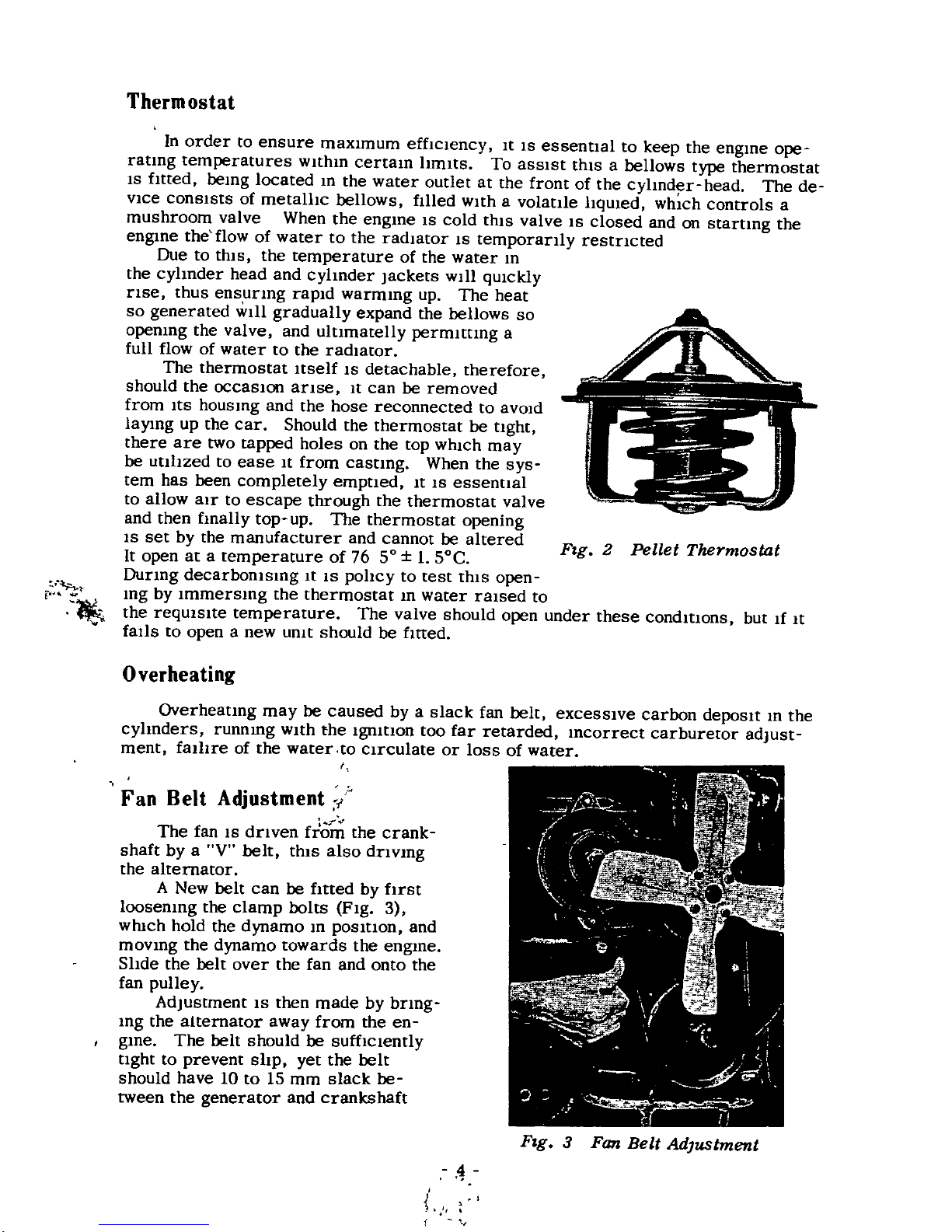
In
order
to
ensure
maXlmum
effIcIency
It
IS
essentlal
to
keep
the
engme
ope
ratlng
temperatures
wIthm
certam
hmlts
To
asslst
thIS
a
bellows
type
thermostat
IS
fitted
bemg
located
m
the
water
outlet
at
the
front
of
the
cyhnd
r
head
The
de
VIce
consIsts
of
metallIc
bellows
filled
wlth
a
volatlle
hquled
whIch
controls
a
mushroom
valve
When
the
engme
IS
cold
thIS
valve
IS
closed
and
on
startmg
the
engme
the
flow
of
water
to
the
radiator
IS
temporarIly
restncted
Due
to
thlS
the
temperature
of
the
water
m
the
cyhnder
head
and
cyhnder
Jackets
wIll
qUlckly
nse
thus
ensunng
rapId
warmmg
up
The
heat
so
generated
w1l1
gradually
expand
the
bellows
so
openIng
the
valve
and
ultlmatelly
permIttmg
a
full
flow
of
water
to
the
radiator
The
thermostat
Itself
IS
detachable
therefore
should
the
occaSlOn
anse
It
can
be
removed
from ItS
housmg
and
the
hose
reconnected
to
avoid
la
lng
up
the
car
Should
the
thermostat
be
tlght
there
are
two
capped
holes
on
the
top
WhICh
may
be
utlhzed
to
ease
It
from
castmg
When
the
sys
tern
has
been
completely
emptled
It
IS
essennal
to
allow
air
to
escape
through
the
thermostat
valve
and
then
fmally
top
up
The
thermostat
opening
IS
set
by
the
manufacturer
and
cannot
be
altered
It
open
at
a
temperature
of
76
SO
II
SoC
Durmg
decarbomsmg
It
IS
pohcy
to
test
thIS
open
mg
by
Immersmg
the
thermostat
m
water
raIsed
to
the
requlslte
temperature
The
valve
should
open
under
these
condmons
but
1f
It
falls
to
open
a new
unIt
should
be
fltted
Thermostat
M
Overheating
Fig
2
Pellet
Thermostat
Overheatlng
may
be
caused
by
a
slack
fan
belt
exceSSIve
carbon
deposlt
m
the
cyhnders
runnmg
WIth
the
19mtlOn
too far
retarded
mcorrect
carburetor
adJust
ment
falhre
of
the
water
to
cIrculate
or
loss
of
water
I
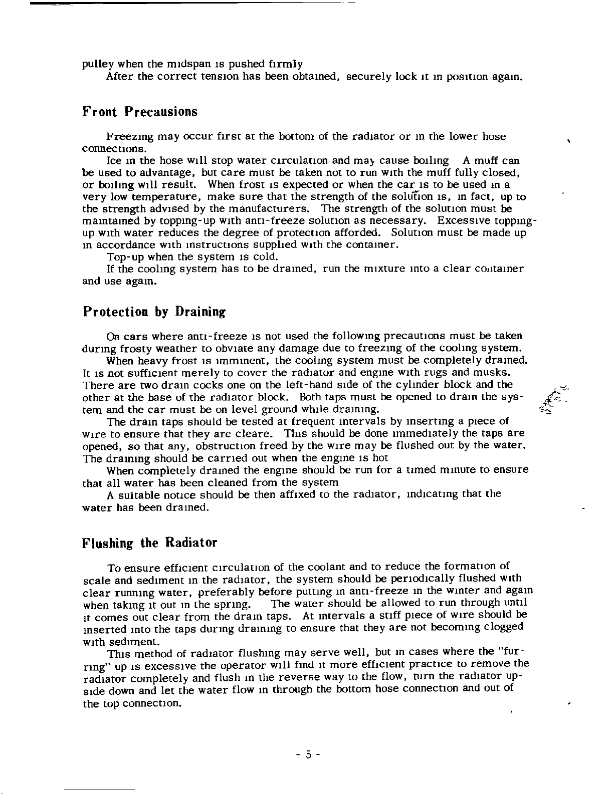
Fan
Belt
Adjustment
r
The
fan
IS
dnven
from
the
crank
shaft
by
a
V
belt
thIS
also
dnvmg
the
alternator
A
New
belt
can
be
fItted
by
fIrst
loosenIng
the
clamp
bolts
Fig
3
which
hold
the
dynamo
m
posmon
and
movmg
the
dynamo
towards
the
engme
Shde
the
belt
over
the fan
and
onto
the
fan
pulley
Adjustment
IS
then
made
by
bnng
mg
the
alternator
away
from
the
en
gme
The
belt
should
be
sufflclently
tlght
to
prevent
shp
yet
the
belt
should
have
10
to
IS
mm
slack
be
tween
the
generator
and
crankshaft
4
Fig
3
Fan
Belt
Adjustment
pulley
when
the
midspan
IS
pushed
fIrmly
After
the
correct
tenslOn
has
been
obtamed
securely
lock
It
m
pOSItlOn
agam
Front
Precausions
Freezmg
may
occur
fIrst
at
the
bottom
of
the
radIator
or
m
the
lower
hose
connectlons
Ice
m
the
hose
wlll
stop
water
clrculatlOn
and
ma
cause
bollmg
A
muff
can
be
used
to
advantage
but
care
must
be
taken
not
to
run
with
the
muff
fully
closed
or
bollmg
WIll
result
When
frost
IS
expected
or
when
the
car
IS to
be
used
m
a
very
low
temperature
make
sure
that
the
strength
of
the
solUtion
IS
m
fact
up
to
the
strength
advised
by
the
manufacturers
The
strength
of
the
solutlon
must
be
mamtamed
by
toppmg
up
WIth
antl
freeze
solutlon
as
necessary
ExceSSive
toppmg
up
WIth
water
reduces
the
degree
of
protection
afforded
Solutlon
must
be
made
up
m
accordance
WIth
mstruCtlons
supphed
WIth
the
contamer
Top
up
when
the
system
IS
cold
If
the
coohng
system
has
to
be
dramed
run
the
mIxture
mto
a
clear
co
ltamer
and
use
agam
Protection
by
Draining
On
cars
where
anti
freeze
IS not
used
the
followmg
precautlons
must
be
taken
dUring
frosty
weather
to
obVIate
any
damage
due
to
freezmg
of
the
coohng
system
When
heavy
frost
IS
Immment
the
coohng
system
must
be
completely
dramed
It
IS not
suffICIent
merely
to
cover
the
radiator
and
engme
WIth
rugs
and
musks
There
are
two
dram
cocks
one on
the
left
hand
Side
of
the
cyhnder
block
and
the
other
at
the
base
of
the
radIator
block
Both
taps
must
be
opened
to
dram
the
sys
tern
and
the
car
must
be
on
level
ground
while dram
mg
The
dram
taps
should
be
tested
at
frequent
mtervals
by
msertmg
a
piece
of
WIre
to
ensure
that
they
are
cleare
This
should
be
done
Immediately
the
taps
are
opened
so
that
any
obstructlOn
freed
by
the
wire
may
be
flushed
out
by
the
water
The
drammg
should
be
carried
out
when
the
engme
IS
hot
When
completely
dramed
the
engme
should
be
run
for
a
tlmed
mmute
to
ensure
that
all
water
has
been
cleaned
from
the
system
A
suitable
notIce
should
be
then
affIxed
to
the radIator
mdlcatmg
that
the
water
has
been
dramed
I
Flushing
the
Radiator
To
ensure
effICient
clrculatlon
of
the
coolant
and
to
reduce
the
formation
of
scale
and
sediment
m
the
radIator
the
system
should
be
perloc
hcally
flushed
With
clear
runnmg
water
preferably
before
putting
m
anti
freeze
m
the
winter
and
agam
when
takmg
It
out
m
the
spring
The
water
should
be
allowed
to
run
through
until
It
comes
out
clear
from
the
dram
taps
At
mtervals
a
Stlff
piece
of
WIre
should
be
mserted
mto
the
taps
dUring
drammg
to
ensure
that
they
are
not
becommg
clogged
WIth
sediment
ThIS
method
of
radIator
flushmg
may
serve
well
but
m
cases
where
the
fur
ring
up
IS exceSSIve
the
operator
WIll
fmd
It
more
effICient
practice
to
remove
the
radiator
completely
and
flush
m
the
reverse
way
to
the
flow
turn
the
radiator
up
Side
down
and
let
the
water
flow
m
through
the
bottom
hose
connectlon
and
out
of
the
top
connectlOn
5
r
J
0
f
seat
F10attng
Sea
o
pulley
ZlO
l
10600
p3ltn
m
dt3
ZlO
l
10800
lo
3m
m
dta
lock
Gasket
H
ub
rOT
an
6
pumP
pulley
f
l
rt
v
I
II
tilT
l
i
II
Fan
belt
Z1061
10600
Zl061
10800
used
foT
zMB
type
batteTY
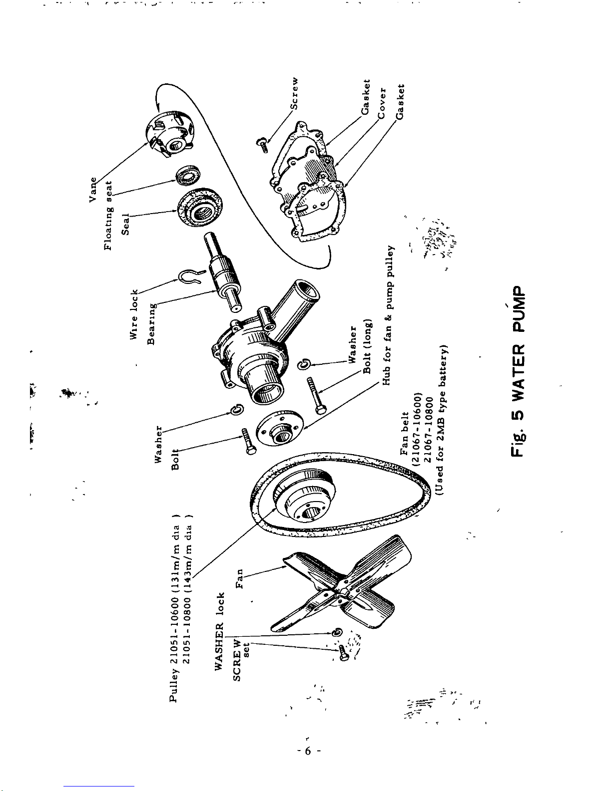
Fig
5
WATER
pUMP
I
WATER
PUMP
After
drammg
the
water
from
the
radiator
remove
the
pump
umt
from
the
cyhnder
block
by
takmg
off
the
fan
belt
and
releasmg
the
setbolts
with
spnng
washers
and
hmge
bolts
to
dynamo
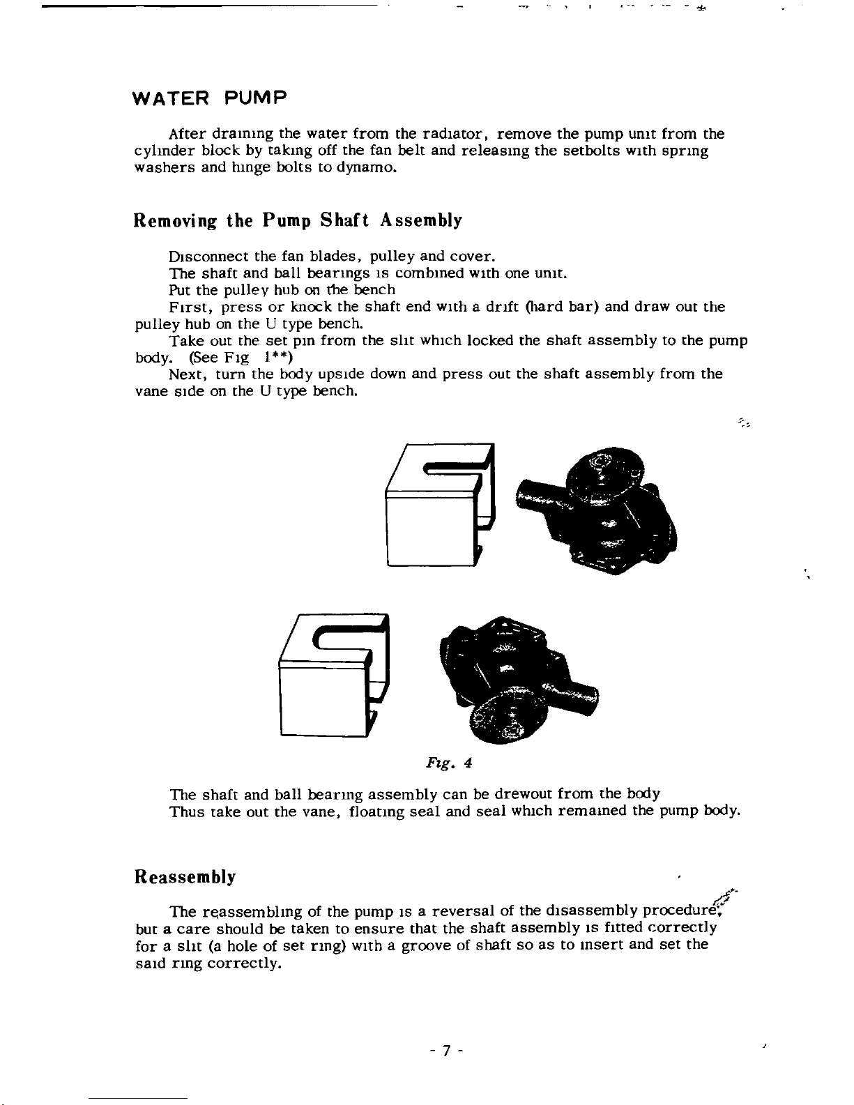
Removing
the
Pump
Shaft
Assembly
Dlsconnect
the
fan
blades
pulley
and
cover
The
shaft
and
ball
beanngs
IS
combmed
with
one
umt
Put
the
pulley
hub
on
the
bench
First
press
or
knock the
shaft
end
with
a
dnft
hard
bar
and
draw
out
the
pulley
hub
on
the
U
type
bench
Take
out
the
set
pm
from
the
sht
which
locked
the
shaft
assembly
to
the
pump
body
See
Fig
1
Next
turn
the
body
upside
down
and
press
out
the
shaft
assembly
from
the
vane
side
on
the
U
type
bench
Fig
4
The
shaft
and
ball
beanng
assembly
can
be
drewout
from
the
body
Thus take
out
the
vane
floatmg
seal
and
seal
WhICh
remamed
the
pump
lxxly
Reassembly
I
1
The
r
assembhng
of
the
pump
IS
a
reversal
of
the
dlsassemb
y
procedure
but
a
care
should
be
taken
to
ensure
that
the
shaft
assembly
IS
fmed
correctly
for
a
sht
a
hole
of
set
nng
with
a
groove
of
shaft
so
as
to
msert
and
set
the
said
nng
correctly
7
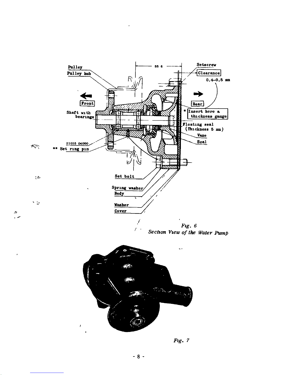
Pu
lley
Pulley
1mb
Set
crew
I
frontl
K
21035
0
000
Set
rUle
p1n
Waaher
Cover
ll
f
Flg
6
Secnon
Vlew
of
the
Water
Pump
FIg
7
8
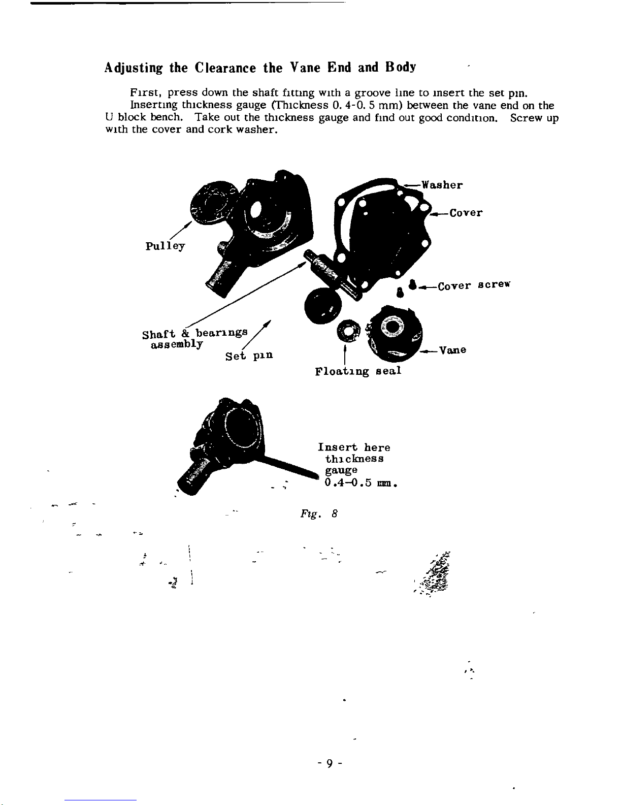
Adjusting
the
Clearance
the
Vane
End
and
Body
FIrst
press
down
the
shaft
fItting
WIth
a
groove
line
to
Insert
the
set
pin
inserting
thIckness
gauge
fhlckness
O4O
5
mm
between
the
vane
end
on
the
U
block
bench
Take
out
the
thIckness
gauge
and
find
out
good
condmon
Screw
up
WIth
the
cover
and
cork
washer
screT
Shaft
bear1ngs
assembly
Set
p1n
o
f
Vane
Float1ng
sea
l
I
1
1
r
I
J
Insert
here
th1ckness
gauge
0
40
5
mm
4
i
4r
ii
Fig
8
1
ff
9
LUBRICATION
Circulation
Pressure
lubncauon
IS
used
throughout
the
umt
and
IS
provided
by
an
ecentnc
non
drammg
011
pump
The
011
pump
IS
bolted
mto
the
left
hand
side
of
the
crank
case
and
IS
driven
from
the
camshaft
gear
by
a
short
verucal
shaft
OllIS
drawn
mto
the
pump
via
the
fIlter
and
IS
dehvered
through
mternal
oil
ways
to
the
non
adjustable
rehef
valve
which
IS
situated
at
the
rear
left
hand
side
of
the
crankcase
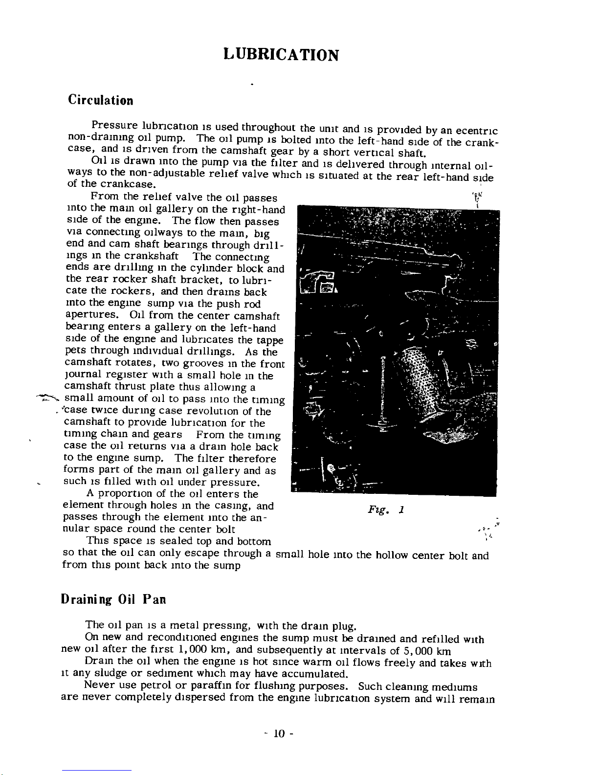
From
the
rellef
valve
the
011
passes
mto
the
mam
011
gallery
on
the
right
hand
sIde
of
the
engme
The
flow
then
passes
via
connecung
011ways
to
the
mam
big
end
and
cam
shaft
bearings
through
dnll
mgs
m
the
crankshaft
The
connectmg
ends
are
dnlhng
m
the
cyhnder
block
and
the
rear
rocker
shaft
bracket
to
lubri
cate
the
rockers
and
then
drams
back
mto
the
engme
sump
via
the
push
rod
apertures
all
from
the
center
camshaft
bearmg
enters
a
gallery
on
the
left
hand
Side
of
the
engme
and
lubncates
the
tappa
pets
through
mdlvldual
dnlhngs
As
the
camshaft
rotates
two
grooves
m
the
front
Journal
regIster
WIth
a
small
hole
m
the
camshaft
thrust
plate
thus
allowmg
a
small
amount
of
OIl
to
pass
mto
the
tlmmg
case
twice
durmg
case
revolutIOn
of
the
camshaft
to
provide
lubncatlon
for
the
ummg
cham
and
gears
From
the
tlmmg
case
the
011
returns
VIa
a
dram
hole
back
to
the
engme
sump
The
filter
therefore
forms
part
of
the
mam
OIl
gallery
and
as
such
IS
filled
WIth
011
under
pressure
A
proportion
of
the
011
enters
the
element
through
holes
m
the
casmg
and
F
g
1
passes
through
the
element
mto
the
an
nular
space
round
the
center
bolt
This
space
IS
sealed
top
and
bottom
so
that
the
011
can
only
escape
through
a
small
hole
mto
the
hollow
center
bolt
and
from
thiS
pomt
back
Into
the
sump
Draining
Oil
Pan
The
011
pan
IS
a
metal
pressIng
With
the
draIn
plug
On
new
and
recondmoned
engmes
the
sump
must
be
draIned
and
refilled
with
new
011
after
the
first
I
000
Ian
and
subsequently
at
Intervals
of
5
000
Ian
Dram
the
011
when
the
engme
IS
hot
SInce
warm
OIl
flows
freely
and
takes
with
It
any
sludge
or
sedIment
whIch
may
have
accumulated
Never
use
petrol
or
paraffIn
for
flushIng
purposes
Such
cleamng
medIUms
are
never
completely
dispersed
from
the
engIne
lubricatIOn
system
and
wIll
remaIn
10
II
I
11
to
contammate
any
fresh
011
This
may
cause
premature
bearmg
faIlure
Oil
Pressure
The
normal
operatmg
011
pressure
IS
60
lb
per
sq
m
The
warnIng
hght
whIch
IS
embodied
m
the
mstrument
panel
hght
If
the
011
pressure
drops
below
8
Ib
sq
m
under
these
cIrcumstances
do
not
attempt
to
run
the
engme
or
serIOUS
damage
may
result
Refilling
When
reflllIng
the
sump
do
not
pour
the
011
In
too
qUickly
as
It
may
overflow
from
the
fIller
onflce
and
mIslead
the
operdtor
as
to
the
quantity
of
lubncant
m
the
engme
Before
testing
the
level
of
the
011
ensure
that
the
vehicle
IS
as
near
level
as
pOSSIble
Always
wIpe
the
dIp
stick
clean
WIth
a
non
fluffy
cloth
before
takmg
the
readmg
It
should
be
remembered
that
time
must
be
allowed
for
new
011
to
reach
to
sump
before
readmg
the
dIpstick
Check
for Low Oil
Pressure
Check
the
level
of
011
In
the
engme
sump
by
means
of
the
dIp
stick
and
top
upIfnecessary
If
the
warnmg
lIght
IS
still
on
after
refIllmg
the
sump
SWItch
off
and
ascertam
that
the
gauge
stramer
m
the
sump
IS
clean
and
not
choked
with
sludge
sale
that
no
aIr
leakage
eXIsts
at
the
stramer
unIOn
on
the
suction
SIde
of
the
011
pump
bemg
defectIve
remove
the
unIt
and
rectify
the
fault
0
1
j
c
c
c
c
3
r
j
I
I
r
r
2
4
j
I
tb
C
j
i
f
3
I
Oil
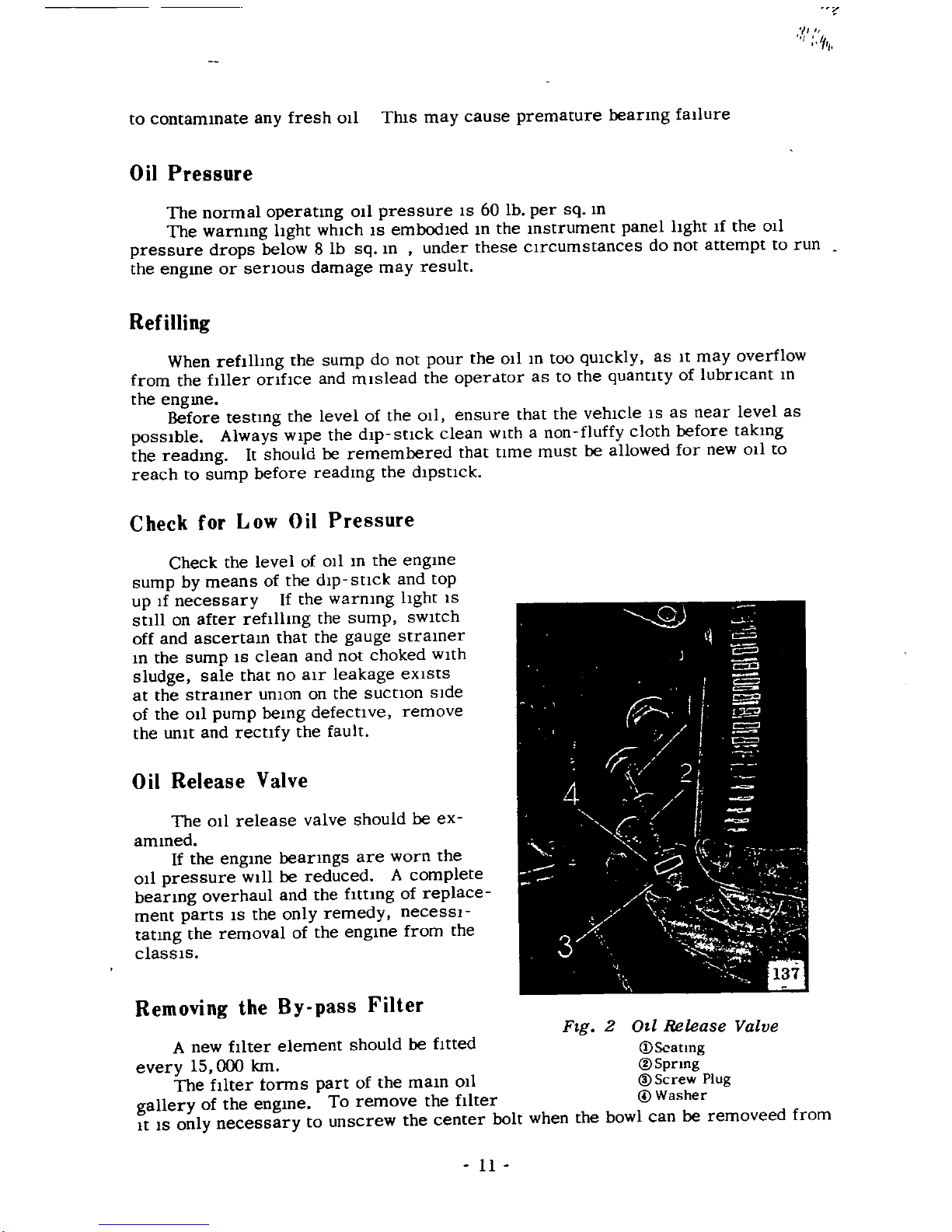
Release
Valve
The
011
release
valve should
be
ex
ammed
If
the
engme
beanngs
are
worn
the
011
pressure
WIll
be
reduced
A
complete
bearmg
overhaul
and
the
fIttmg
of
replace
ment
parts
IS
the
only
remedy
necessl
tatmg
the
removal
of
the
engme
from
the
classls
0
Removing
the
By
pass
Filter
FJg
2
OJl
Release
Valve
A
new
fIlter
element
should
be
fItted
DScatmg
every
15
000
km
@Spnng
The
fIlter
torms
part
of
the
mam
011
@Screw
Plug
gallery
of
the
engme
To
remove
the
fllter
@
Washer
It
IS
only
necessary
to
unscrew
the
center
bolt
when
the
bowl
can
be
removeed
from
11
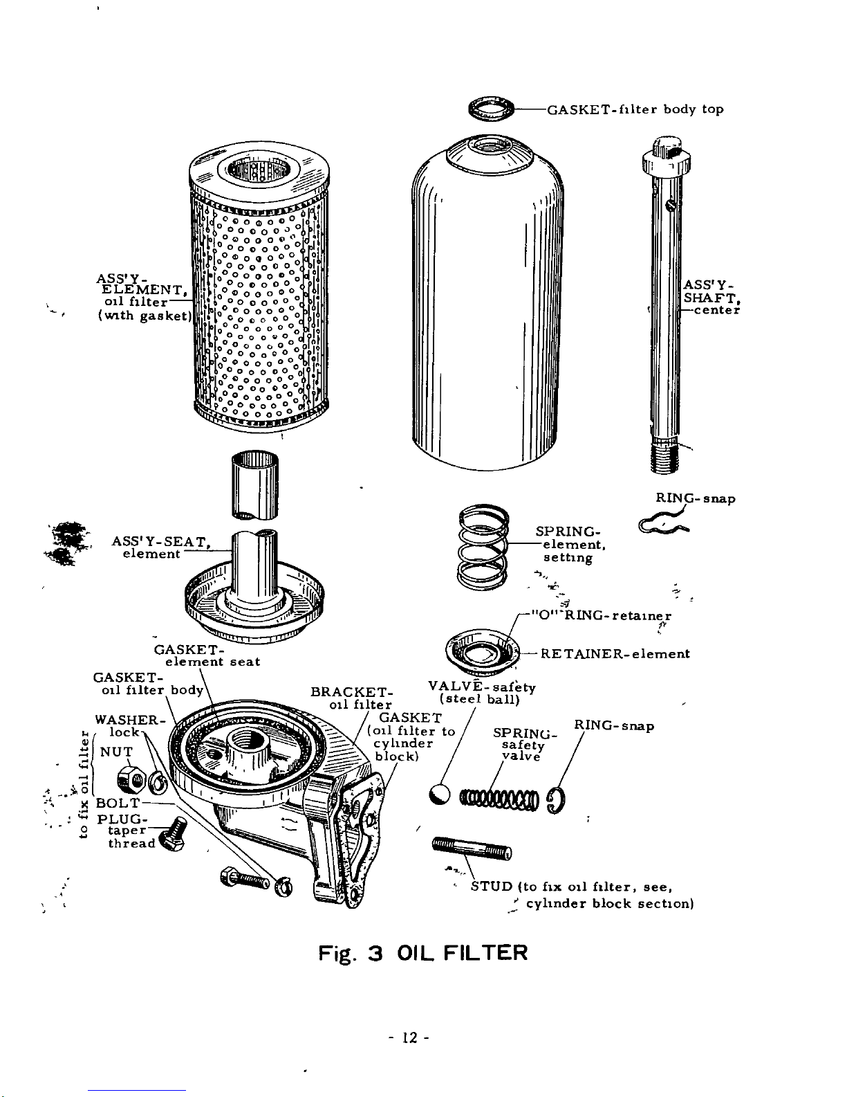
GASKET
fllter
body
top
r
1
ASS
Y
ELEMENT
011
fllter
With
gasket
ASS
Y
SHAFT
center
ASS
Y
SEAT
element
PRING
element
settIng
c
RING
snap
C
GASKET
element
seat
GASKET
011
filter
body
O
RlNG
retainer
RETAlNER
ele
ent
BRACKET
V
ALVE
safety
011
filter
steel
ball
GASKET
RING
sna
011
fllter
to
SPRINGI
p
cyhnder
safety
o
k
o
I
STUD
to
fix
011
fllter
see
cyhnder
block
sechon
Fig
3
01
L
FILTER
12
the
crankcase
complete
with
the
element
Take
care
not
to
lose
the
rubber
sealing
ring
Remove
the
element
and
note
the
assembly
of
the
components
Wash
out
the
bowl
with
pettol
so
that
It
IS
clean
It
IS
Important
to
thorough
dry
the
bowl
to
obviate
any
contammaUon
of
the
lubrIcatmg
011
Replacing
the
Filter
With
the
center
bolt
the
washer and
the
spring
together
with
the
collar
m
POSI
tIOn
In
the
bowl
msert
a
new
element
Place
the
dIstance
pIece
over
the
center
bolt
with
the
flanged
end
towards
the
element
The
bowl
of
filter
must
now
be
filled
with
011
Offer
up
the
complete
assembly
to
the
engme
and
secure
mto
posItion
by
means
of
the
center
bolt
Removing
the
Oil
Pan
The
sump
capacity
IS
3IInres
Dram
the
011
and
replace
the
dram
plug
Remove
the
set
screw
bolts
which
are
mserted
from
the
underSIde
of
the
se
cUring
flange
and
the
lower
bolts from
the
bottom
edge
of
the
bell
housmg
Lower
the
011
pan
from
the
engme
takmg
care
not
to
damage
the
Jomt
wahsers
In
the
pro
cess
Removing
the
Strainer
WIth
the
snup
lowered
It
IS
possIble
to
remove
the
011
stramer
through
which
011ISdrawn
mto
the
011
pump
To
remove
the
straIner
unto
the
unIOn
connecung
the
011
pIck
up
to
the
pump
and
unscrew
the
securmg
bolts
The
stramer
may
be
dIsmantled
for
cleanmg
purpose
by
removmg
the
delivery
pipe
flange
bolts
NotIce
that
there
are
the
dowel
pms
to
the
cover
whIch
must
be
posItIOned
cor
rectly
when
refItung
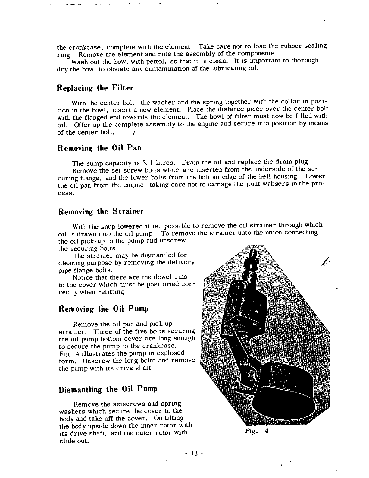
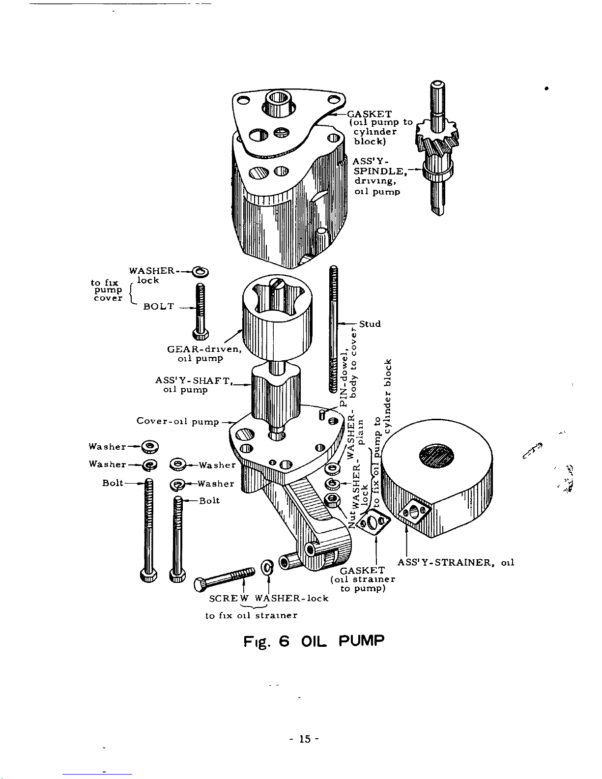
Removing
the
Oil
Pump
Remove
the
Oil
pan
and
pick
up
straIner
Three
of
the
fIve
bolts
securing
the
011
pump
bottom
cover
are
long
enough
to
secure
the
pump
to
the
crankcase
FIg
4
Illustrates
the
pump
m
explosed
form
Unscrew
the
long
bolts
and
remove
the
pump
With
ItS
drive
shaft
Dismantling
the
Oil
Pump
Remove
the
setscrews
and
spring
washers
WhICh
secure
the
cover
to
the
body
and
take
off
the
cover
On
ultmg
the
body
upSIde
down
the
mner
rotor
WIth
Its
drive
shaft
and
the
outer
rotor
WIth
slide
out
Ftg
4
13
Refitting
the
Sump
Clean
out
the
sump
by
washing
It
10
paraffm
the
care
to
remove
any
traces
of
the
paraffm
before
refIttmg
the
011
pan
to
the
engme
Pay
patlcular
attentlon
to
the
011
pan
and
crank
case
lomt
faces
and
remove
any
traces
of
old
Jomnng
materIal
Examme
the
Jomt
washer
and
renew
It
1f
necessary
The
old
Jomt
washer
can
be
used
agam
If
It
IS
sound
but
It
IS
adVIsable
to
fIt a
new
one
Smear
the
faces
of
the
Jomt
WIth
grease
and
fIt
the
Jomt
washer
LIft
the
011
pan
mto
poSl
non
and
msert
the
setscrews
mto
the
flange
tlghtmg
them
up
evenly
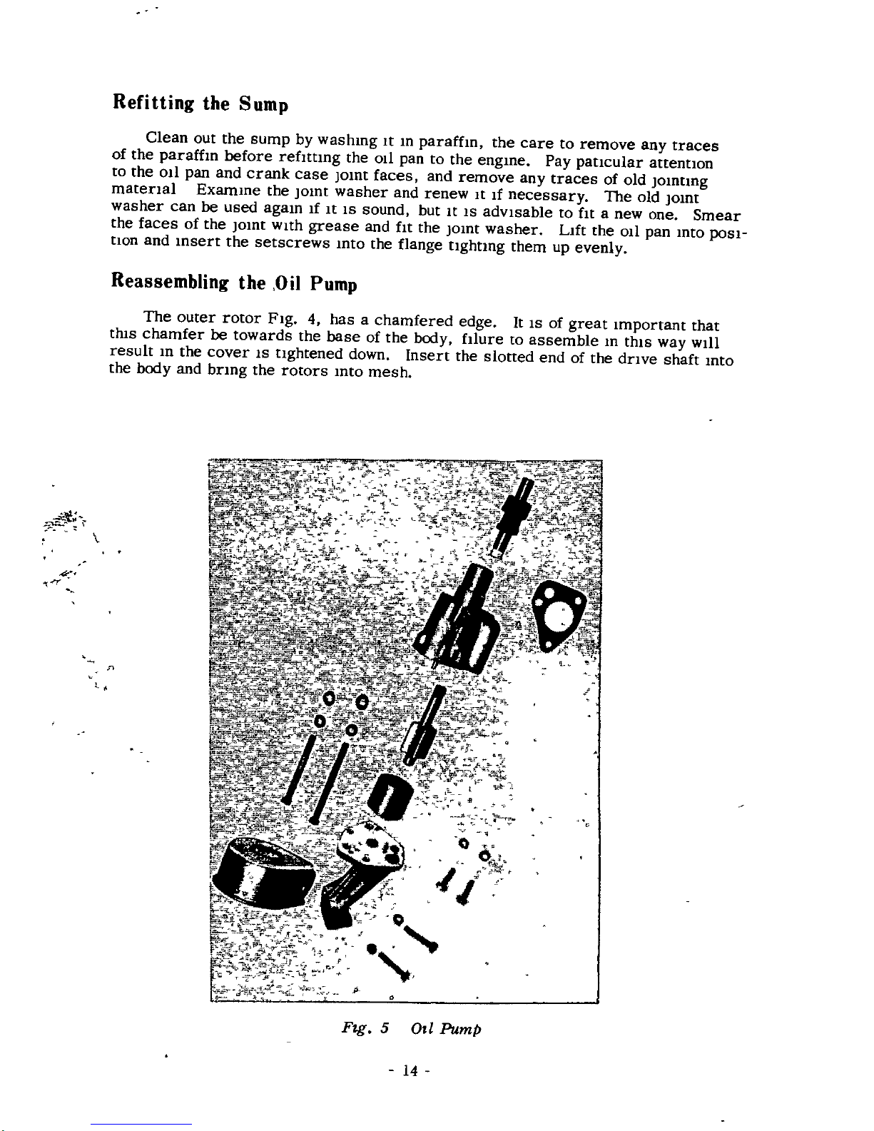
Reassembling
the
Oil
Pump
The
outer
rotor
Fig
4
hasachamfered
edge
It
IS
of
great
Important
that
thIS
chamfer
be
towards
the
base
of
the
body
fIlure
to
assemble
m
thiS
way
WIll
result
10
the
cover
IS
tlghtened
down
Insert
the
slotted
end
of
the
drIve
shaft
mto
the
body
and
brIng
the
rotors
mto
mesh
n
t
r
1
y
o
l
fuo
f
0
i
P
Fzg
5
OJl
Pump
14
to
ilx
pump
cover
WASHER
O
k
I
BOLT
i
ASS
Y
SHAFT
0
1
pump
Cover
oll
pump
Washer
@
Washer
Washer
Bolt
@
Washer
Bolt
SCREW
WASHER
lock
to
ilx
0
1
stralner
GASKET
011
pump
to
cyhnder
bloc
k
ASS
Y
SPINDLE
drlVlng
011
pump
Stud
0
u
0
0
00
0
D
p
1
GASKET
ot
stramer
to
pump
Fig
6
OIL
PUMP
15
U
o
D
tf
t
ASS
Y
STRAINER
011
 Loading...