

Datsun 320 Service manual
tO
t
e
DATSUN TRUCK
MODEL
SfRVICE
NISSAN
A
320
MANUAL
c
f
i
t
l
E
11
lJ
NI55AN
OTEMACHI
CAlLI
MOTOR
BLDG
TOKYO
ADDRISS
HONU
OTEMACHI
JAPAN
I
NISMO
211
I
5281
y
CO
CHIYODA
TOKTO
LTD
KU
Book
t
Sale
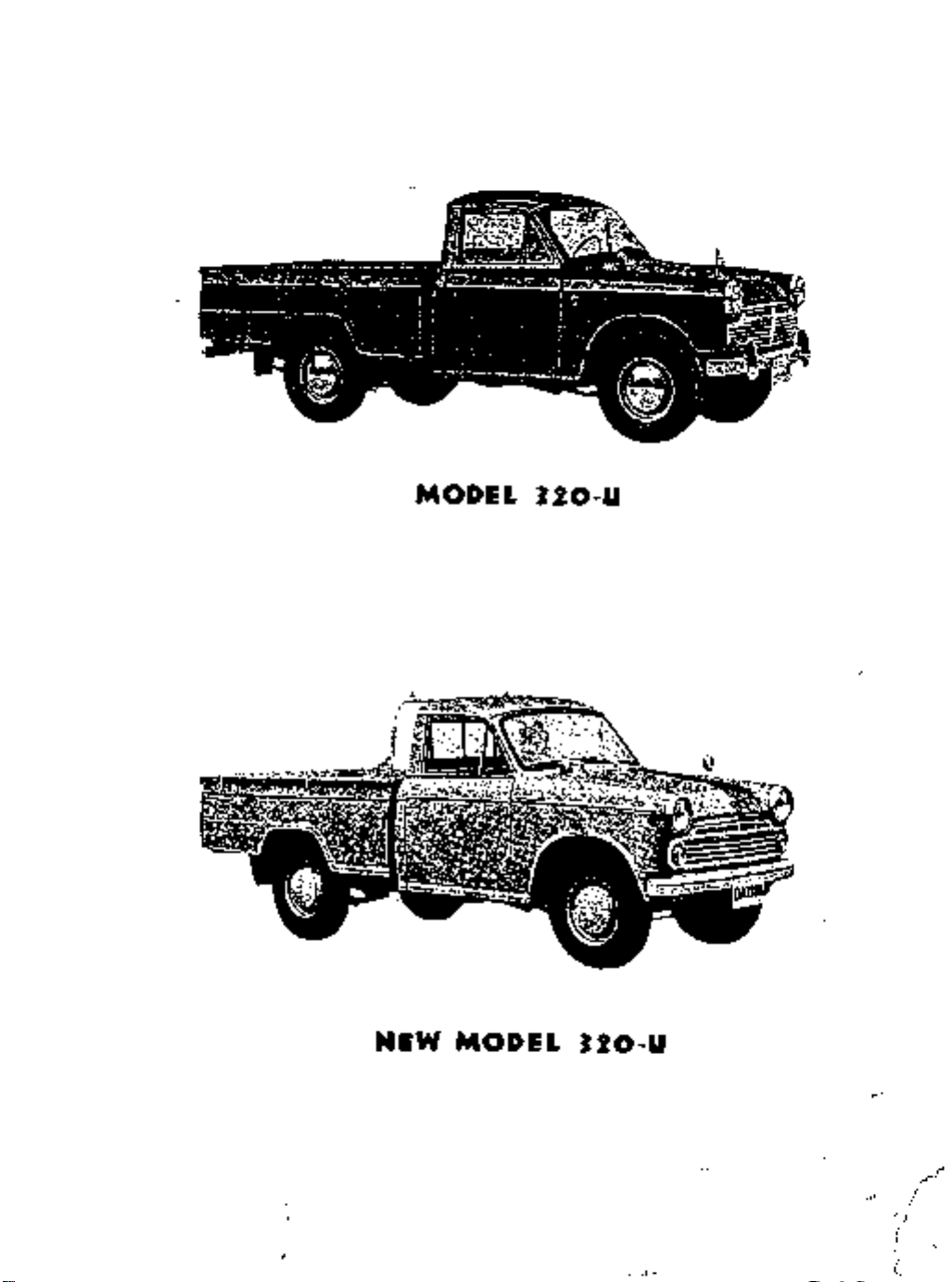
MODEL
1IO
U
NEW
MODEL
1IO
U
I
i

ThIS
INTRODUCTION
has
manual
been
comphes
for
purpose
of
asslstmg
for
effectIve
Model
P
L
components
comprehenSIve
pIete
these
Spare
dlsmanthng
assembltes
IS
It
emphasIsed
Parts
DATSUN
serVIce
320
IS
should
U
descnbed
mstructlOns
be
dIstnbutors
and
Each
assembly
10
assembImg
that
only
used
as
mamtenance
detaIl
are
gIven
and
genuine
replacements
and
dealers
of
the
addItIOn
In
for
mspectlOn
DATSUN
of
major
com
the
of
l
cfi4
SPEClFICA
TION
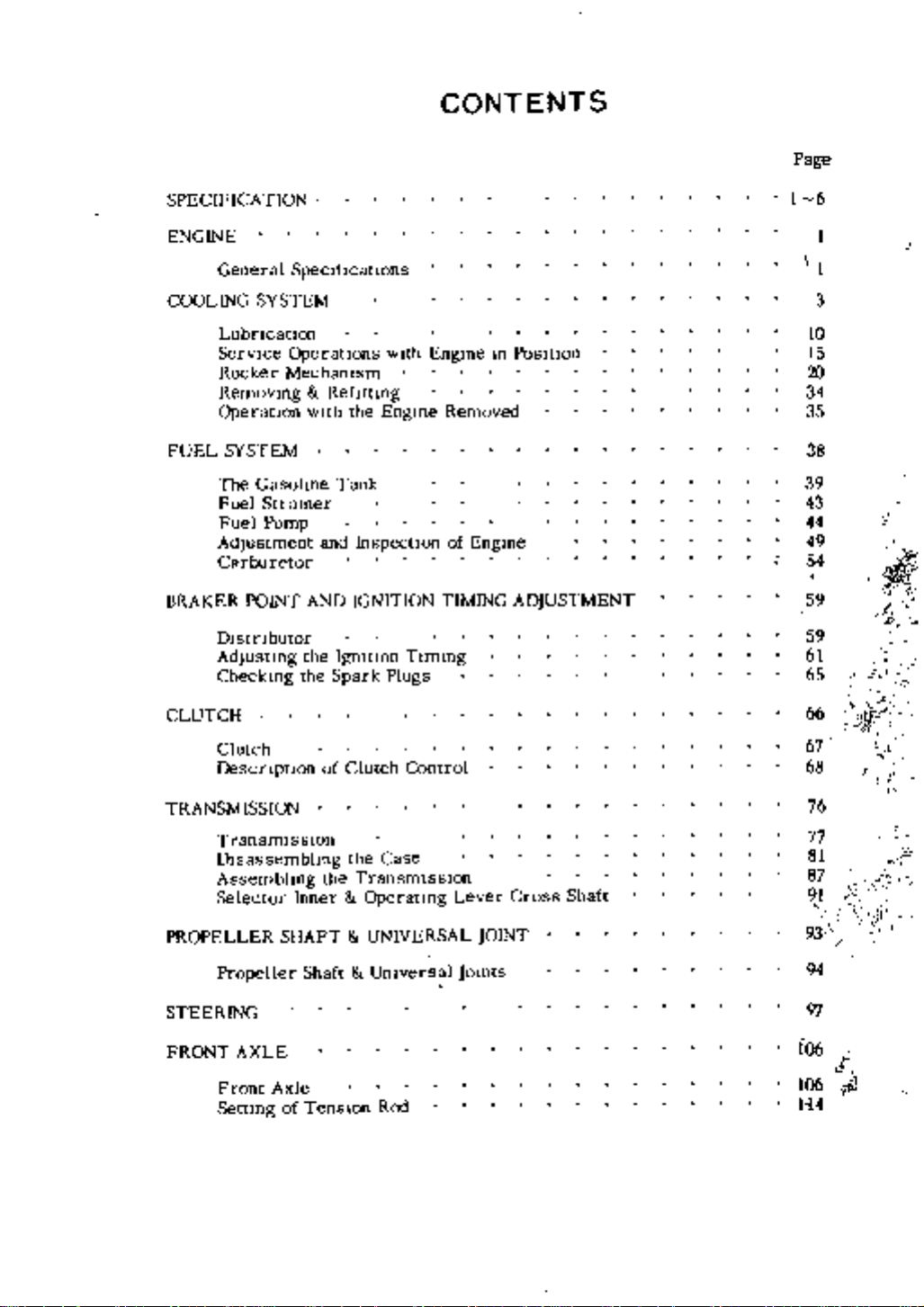
CONTENTS
Page
1
6
ENGINE
General
COOLING
Lubncatlon
ServIce
Rocker
Removmg
OperatIOn
FUEL
BRAKER
SYSTEM
The
Fuel
Fuel
Adjustment
Carburetor
POINT
Dlstnbutor
AdjustIng
CheckIng
CLUTCH
Clutch
Descnptlon
TRANSMISSION
TransmIssIOn
DIsassemblIng
Assembhng
Selector
SpecIftcatlOns
SYSTEM
OperatIOns
Mechamsm
WIth
GasolIne
Strainer
Pump
AND
the
the
Inner
wIth
RefittIng
the
Engme
Tank
and
Inspection
IGNITION
Igmtlon TImIng
Spark
Plugs
of
Clutch
the
the
Control
Case
TransmISSIOn
Operatmg
EngIne
Removed
of
EngIne
TIMING
Lever Cross
In
PosItion
ADJUSTMENT
Shaft
1
1
3
10
15
20
34
35
38
39
43
44
49
54
59
59
61
65
66
67
68
76
77
81
87
91
q
it
0
t
1
U1I
JJ
l
rt
i
1
PROPELLER
Propeller
STEERING
FRONT
Front
Settmg
AXLE
SHAFT
Axle
of
Shaft
TenSIon
UNIVERSAL
Umversal
Rex
JOINT
jomts
93
94
97
106
106
1
14
t
l

Page
REAR
AXLE
Rear
AssemblIng
BRAKE
IGNI
fI0N
ELECTRICAL
Starter
Battery
Axle
SYSFEM
SYSTEM
Motor
Adjustment
117
118
122
138
147
150
164
171
u
c
v
t
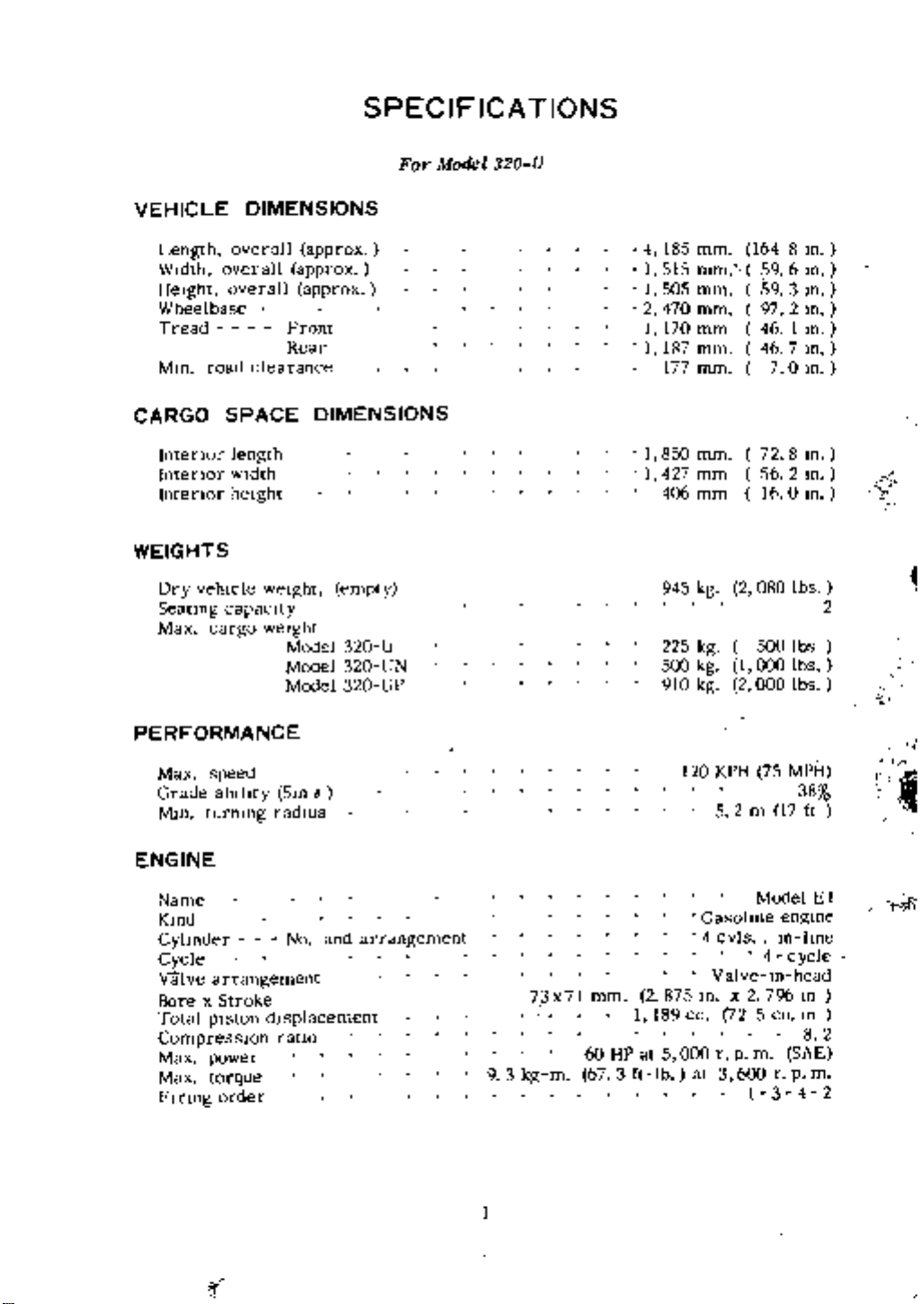
SPECIFICA
For
Model
320
TIONS
U
VEHICLE
Length
WIdth
HeIght
Wheelbase
Tread
Mm
CARGO
Intenor
lntenor
lntenor
WEIGHTS
Dry
Seating
Max
overall
road
vehIcle
cargo
DIMENSIONS
overall
overall
clearance
SPACE
length
wIdth
height
weIght
capacIty
weIght
approx
approx
approx
Front
Rear
DIMENSIONS
empty
Model
Model
Model
320
320
320
U
UN
UP
4
185
mm
1
515
mm
1
50S
mm
2
470
mm
I
170
mm
1
187
mm
177
mm
I
850
mm
1
427
mm
mm
406
945
kg
225
kg
500
kg
910
kg
164
m
8
6
59
m
59
3
m
2
In
97
46
1
In
46
7
m
0
In
7
72
8
m
2
In
56
In
16
0
2
lbs
080
500
lbs
lbs
000
1
2
000
lbs
r
1
2
PERFORMANCE
Max
speed
Grade
Mm
ablhty
turnmg
ENGINE
Name
Kmd
Cyhnder
Cycle
valve
arrangement
BorexStroke
Total
piston
CompressIOn
Max
power
Max
torque
FInng
order
Sm
6
radIUs
and
No
dIsplacement
ratio
arrdngement
9 3
kg
73x7l
J
KPH
75
MPH
120
38
2
m
17
Model
4
m
796
5
engme
m
cycle
head
m
m
cu
SAE
rpm
4 2
3
ft
lme
8
E
1
2
5
Gasohne
4
cvls
Valve
m x
at
2
72
rPm
3
600
1
2
HP
875
1
189
cc
at
5
000
lb
mm
60
m
673ft
t
f
ir
r
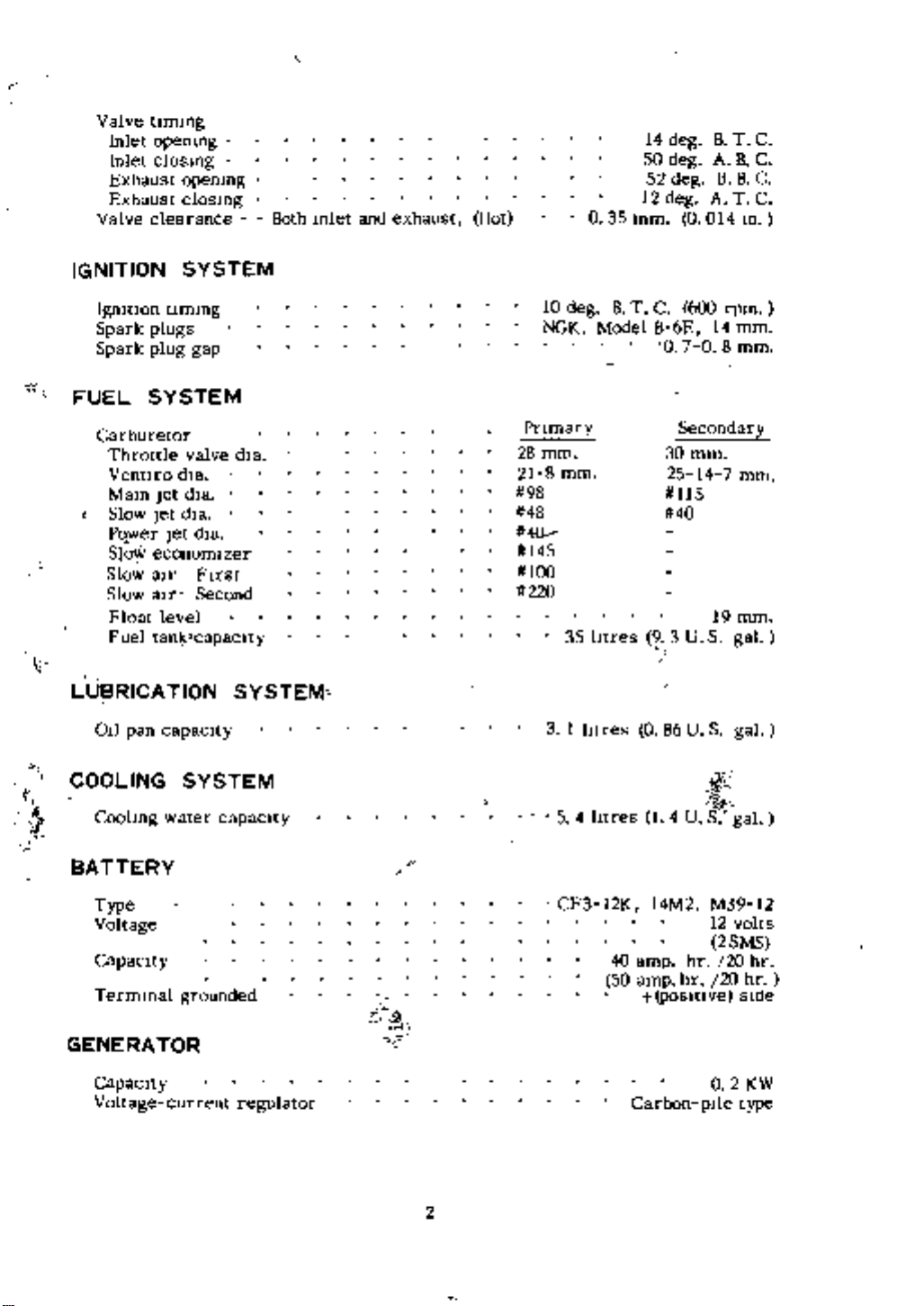
Valve
Inlet
Inlet
Exhaust
Exhaust
Valve
tlmmg
opemng
closmg
opemng
closmg
clearance
Both
m1et
and
exhaust
Hot
14
50
52
12
0
35
mm
deg
deg
deg
deg
0
B
T
ABC
B B
A
T
014
C
C
C
m
t
r
IGNITION
19mtlon
Spark
Spark
FUEL
Carburetor
Throttle
Ventlro
Mam
t
Slow
wer
PQ
Slo
Slow
Slow
Float
Fuel
Llj
RICATION
OIl
pan
COOLING
Coolmg
SYSTEM
tlmmg
plugs
plug
gap
SYSTEM
valve
dla
dla
Jet
dla
Jet
Jet
economlzer
aIr
atr
level
tanJ
l
capacity
SYSTEM
water
dla
FIrst
Second
capaclty
capacIty
dla
SYSTEM
10
NGK
Pnmary
28
mm
21
98
48
4Q
145
100
220
deg
8
mm
35
3
1
htres 0
54htres
Model
htres
BTC
600
6E
B
070
Secondary
30mm
25
115
40
3US
9
86US
14U
14
14
8
19mm
S
rpm
7
mm
mm
mm
gal
gal
gal
BATTERY
Type
Voltage
Capacity
Termmal
GENERATOR
Capacity
Voltage
grounded
current
regulator
CF3
12K
14M2
amp
amp
hr
hr
40
50
posltlve
J
Carbon
2
ptie
M39
12
volts
2
SMS
20
hr
20
sIde
02KW
type
12
hr
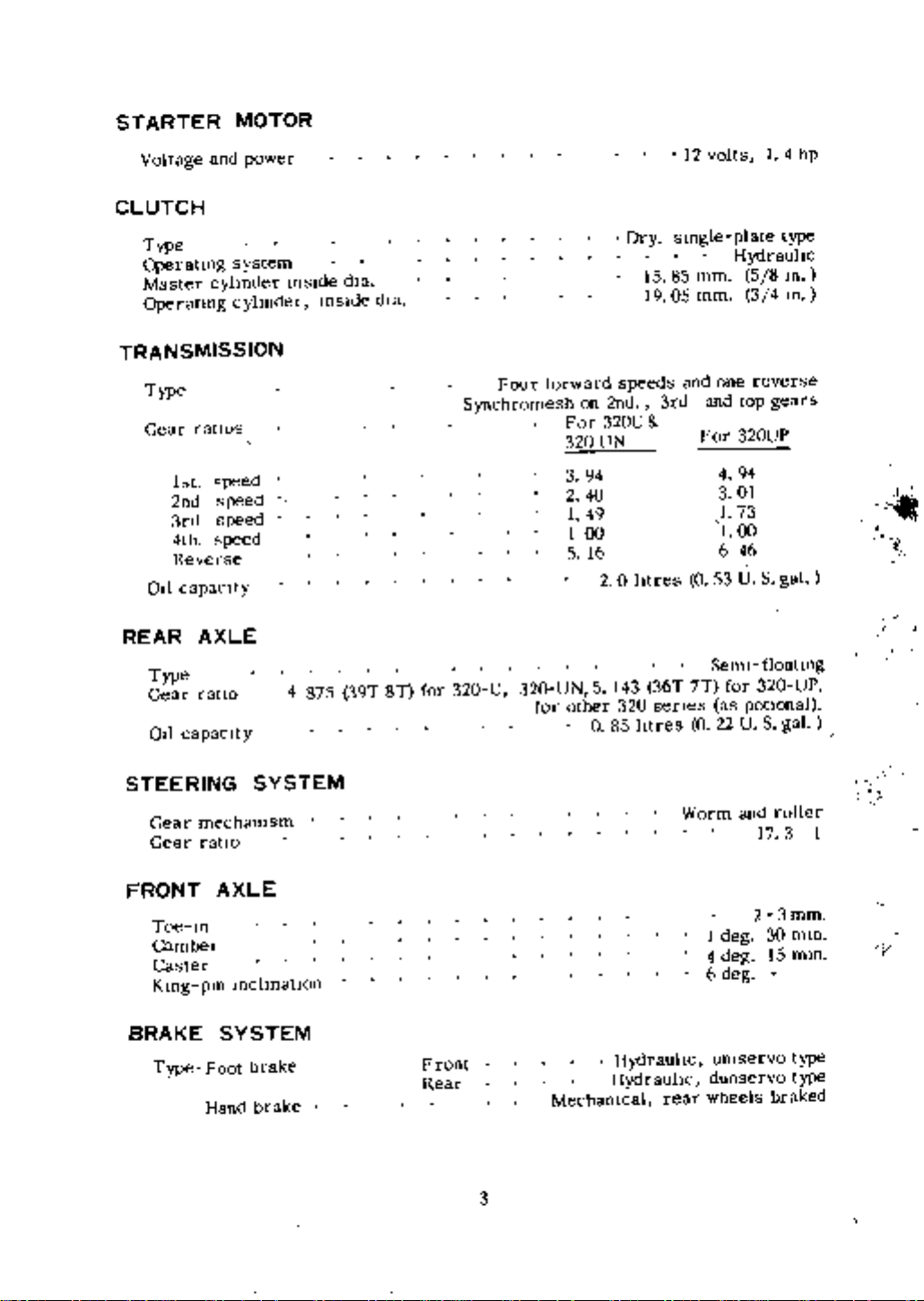
STARTER
Voltage
CLUTCH
and
MOTOR
power
12
volts
4
1
hp
Type
Operating
Master
cyhnder
Operatmg
TRANSMISSION
Type
ratIOs
Gear
1st
speed
2nd
speed
3rcl
speed
4th
speed
Reverse
all
capacIty
REAR
AXLE
Type
ratIo
Gear
all
capacIty
system
cy1mder
mSlde
4
875
mSlde
dla
39T
dza
8T
for
320
Four
forward
Synchromesh
U
320
for
UN
For
320
3
2
1
1
5
other
on
2nd
320U
UN
94
40
49
00
16
2
5
143
320
O
85
Dry
smgle
15 85
19
05mm
speeds
3rd
0 lures 0
36T
senes
htres
and
7T
0
mm
one
and
For
4
3
1
1
6
53
Semi
for
as
22US
type
plate
Hydrauhc
5 8
m
410
3
reverse
top
gears
320UP
94
01
73
00
46
S
U
gal
floatIng
320
potIonal
gal
UP
STEERING
Gear
Gear
FRONT
Toe
m
Camber
Caster
Kmg
BRAKE
Type
mechamsm
ratIO
AXLE
mchnatIon
pm
SYSTEM
Foot
Hand
SYSTEM
brake
brake
Front
Rear
Warm
Hydrauhc
Hydrauhc
Mechanical
3
rear
1
deg
4
deg
6
deg
umservo
duo
wheels
and
servo
17
2
roller
3
3
30
15
braked
mm
mm
min
type
type
I
c
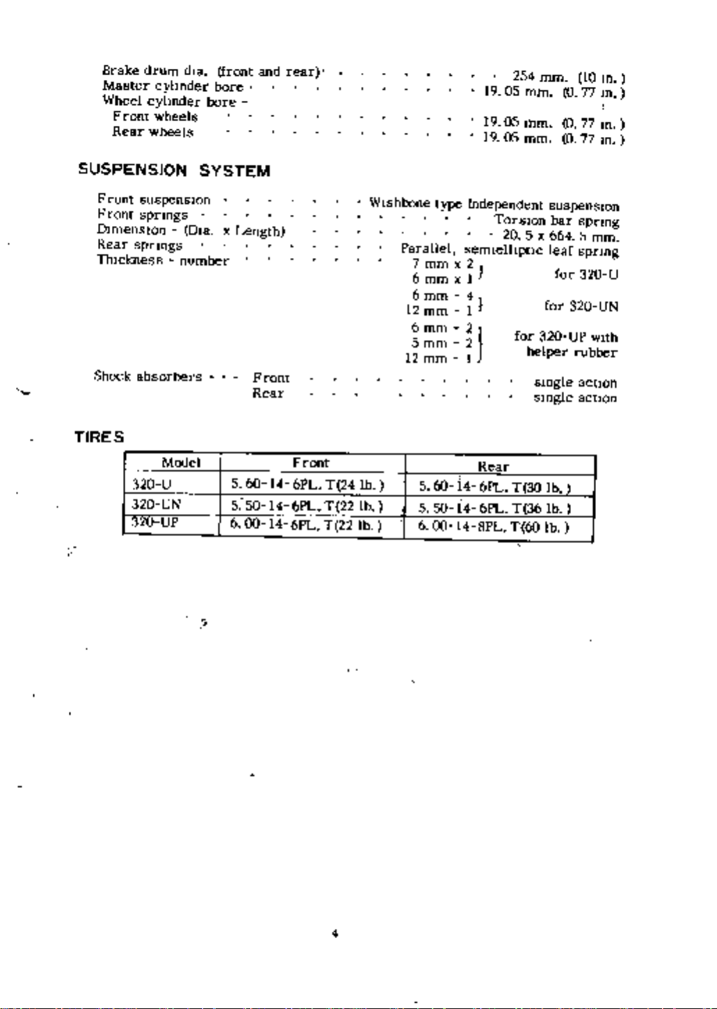
Brake
Master
Wheel
Front
Rear
drum
cylmder
cyhnder
wheels
wheels
dla
bore
bore
front
and
rear
254
rom
19
05
mm
19
05
mm
19
05
mm
10
10
10
0
77
0
77
lD
0
77
lD
SUSPENSWN
Front
Front
DimensIOn
Rear
spnngs
111lckness
Shock
TIRES
320
320
320
suspensIOn
spnngs
absorbers
Model
U
UN
UP
Ola
number
SYSTEM
x
Length
Front
Rear
5
60
5
50
6
00
Wishbone
Front
14
6PL
14
6PL
14
6PL
lb
T
24
T
22
lb
T
22
lb
Parallel
7
6
6mm
12
6mm
5
12
6
type
mm x
mm
mm
mm
mm
5
60 14
5
50
00
Independent
TorsIOn
semlelltptic
2
1
x
4
1
2
1
21
Rear
6PL
6PL
i4
14
8PL
20
5x604
for
helper
30
T
36
T
T
60
suspension
bar
leaf
f
or
for
320
smgle
smgle
lb
lb
lb
spnng
5
spnng
320
320
UP
rubber
action
action
mm
U
UN
With
I
4
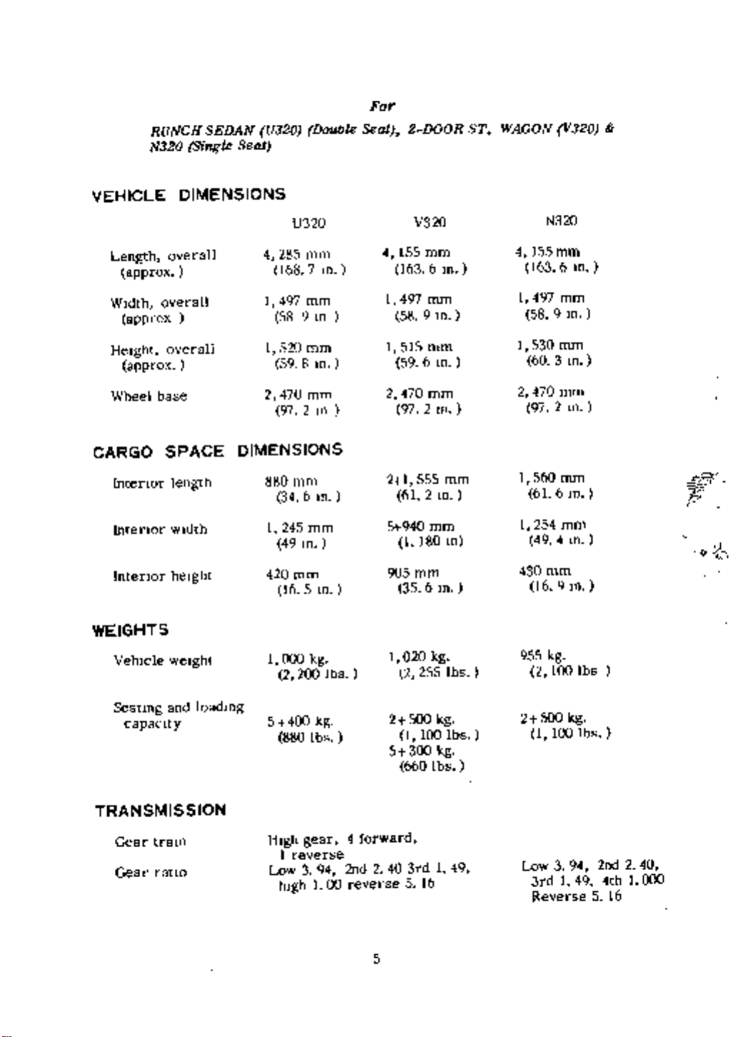
RUNCH
N320
SEDAN
Single
Seat
U320
Double
FOT
Seat
2
DOOR
ST
WAGON
V320
VEHICLE
Length
WIdth
approx
HeIght
approx
Wheel
CARGO
Intenor
Intenor
Intenor
approx
DIMENSIONS
overall
overall
overall
base
SPACE
length
wIdth
heIght
U320
4
285
168
1
497
58
1
520
59
2
470
97
DIMENSIONS
880
mm
34
1
245
49
420
mm
16
V320
mm
7
m
mm
9
10
mm
8
m
mm
2
10
6
m
mm
m
4
155
163
1
497
58
1
515
59
2
470
97
21555
61
5
940
180
1
mm
6
m
mm
9
m
mm
6
m
mm
2
m
mm
2
m
mm
10
N320
4
155
mm
163
6
m
1
497
mm
58
9
m
1
530
mm
60
3
m
2
470
mm
m
97
2
1
560
mm
6
m
61
1
254
mm
4
49
m
F
t
905mm
5
m
35
6
m
430
mm
16
9
m
WEIGHTS
VehIcle
Seatmg
capacIty
weIght
and
TRANSMISSION
Gear
tram
Gear
ratIO
loadmg
1
5
880
HIgh
1
Low
hIgh
000
2
400
reverse
200
gear
3
kg
kg
lbs
94
1
lbs
4
2nd240
reverse
00
forward
5
1
020
2
2
SOO
1
5
300
660
3rd149
5
255
100
16
kg
lbs
kg
kg
lbs
Ibs
955
kg
2
2
500
1
Low
3rd149
Reverse
100
100
3
lbs
kg
1bs
94
2nd240
4th1000
16
5
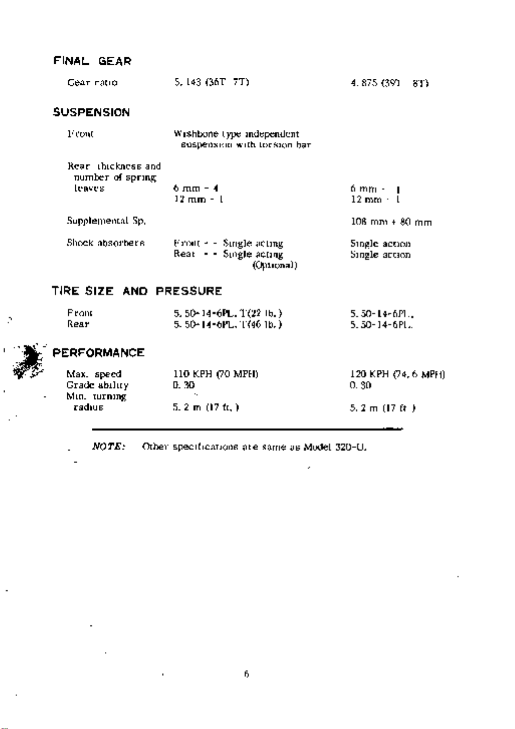
FINAL
GEAR
Gear
ratIO
5
143
36T
7T
4
875
39T
8T
SUSPENSION
Front
Rear
thickness
number
of
leaves
Supplemental
Shock
absorbers
spnng
Sp
and
Wishbone
suspensIOn
6
mm
12
mm
Front
Rear
4
I
type
wIth
Single
Single
Independent
torsIOn
acting
acting
bar
6
mm
mm
12
108
Single
Single
mm
action
action
I
1
80
mm
Optional
TIRE
1
PERFORMANCE
Front
Rear
SIZE
AND
PRESSURE
5
50
5
50
l4
6PL
T
22
lb
14
6PL
T
46
lb
5
14
50
5
50
6PL
14
6PL
iT
Max
speed
Grade
Min
ability
turning
radIus
NOTE Other
110
KPH
70
0
30
2
5
17
m
speclftcatlOns
320
120
0
5 2
30
U
MPH
ft
are
same
as
Model
KPH
m
17
74
6 MPH
ft
6
ENGINE
I
c
l
1
I
I
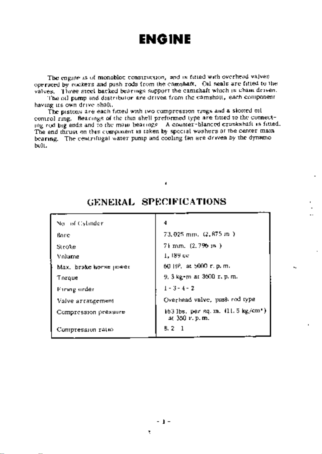
ENGINE
The
operated
valves
The
havmg
The
control
rod
109
The
end
beanng
belt
own
IS
rockers
steel
pump
dnve
engme
by
Three
OIl
Its
pIstons
nng
bIg
No
Bore
thrust
The
Beanngs
ends
on
centnfugal
of
Cyhnder
Stroke
Volume
Max
brake
Torque
Flnngorder
Valve
arrangement
CompressIOn
CompressIOn
of
monobloc
and
push
backed
and
dlstnbutor
shaft
each
are
of
and
this
the
to
component
GENERAL
horse
pressure
ratio
htted
the
malO
water
power
construction
rods
beanngs
with
thm
beanngs
pump
and
from
the
camshaft
the
from
compressIOn
preformed
A
counter
by
specIal
coolmg
are
IS
support
dnven
two
shell
taken
and
SPECIFICATIONS
4
73
025
mm
71
1
189
60
HP
9 3
kg
1
3
Overhead
lbs
163
at
350
2
8
1
IS
fitted
camshaft
the
type
washers
fan
mm
2
cc
at
m
4 2
per
r
camshatt
rmgs
blanced
are
796
5000
at
valve
p
011
are
2
3600
sq
m
with
whIch
dnven
875
m
r
seals
and
fitted
p
rpm
push
m
overhead
are
IS
each
a
slotted
to
crankshaft
at
the
by
m
m
rod
11
fItted
cham
component
the
center
the
type
5
kg
valves
to
dnven
011
connect
IS
fitted
malO
dynamo
cm
the
1
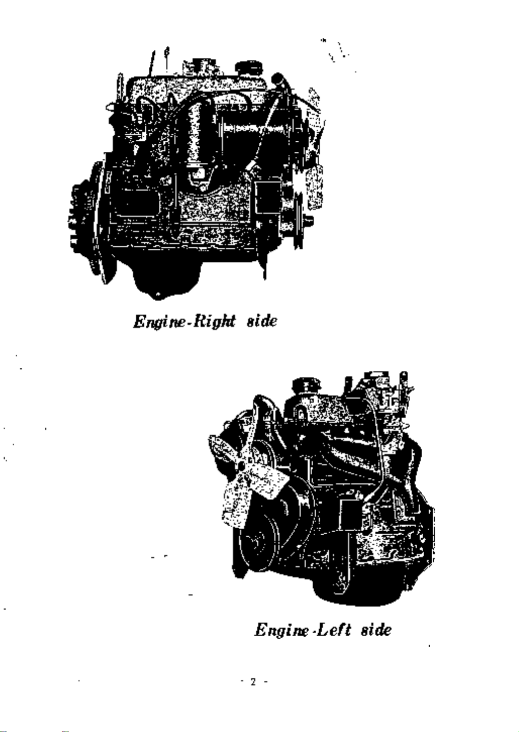
Engine
1
side
Right
Engine
2
Left
side
COOLING
SYSTEM
effIcIent
An
runmng
Its
of
maIntance
Description
The
The
coohng
system
cap
the
engIne
water
an effIcient
fIller
remove
If
the
place
If
pOSSIble
the
fan
controls
ftller
IS
lost
use
coohng
engIne
system
cooled
IS
cap
runmng
through
clean
system
and
It
IS
maIntaIned
radIator
pressunsed
the
pressure
If
the
ToppIng
the
soft
water
IS
therefore
IS
and
and
at
temperature
overflow
of
major
necessary
water
by
thermostat
the
rehef
approxImately
of
should
up
pIpe
Importance
pump
valve
the
coolant
only
Top
to
pay
CIrculation
Incorporated
4
O
be
requIred
when
up
kg
IS
to
above
ensure
patlcular
per
sq
occasIOnally
the
engIne
the
attention
combIned
the
10
cm
IX
Jhng
IS
satisfactory
to
wIth
radIator
not
Do
or
poInt
to
re
cold
and
li
j
l
engIne
the
of
FIll
to
IS
system
cold
wIthIn
may
IS
1
cause
the
2
of
water
approxImately
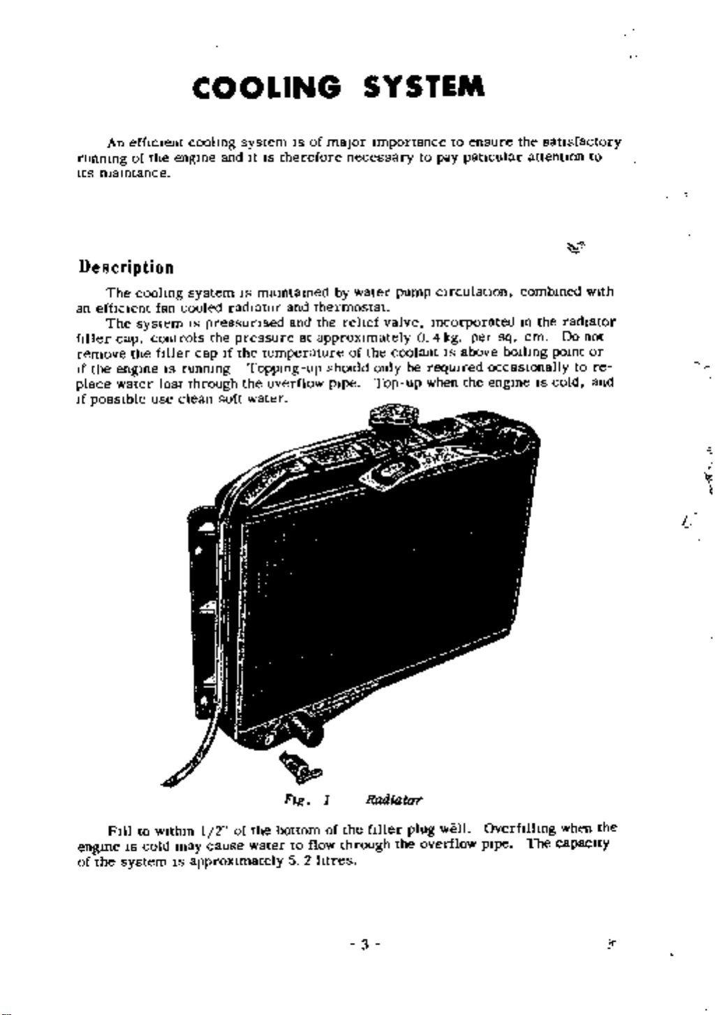
Fig
bottom
to
5
flow
2
1
of
htres
Rmliator
the
fIller
through
3
the
plug
well
overflow
OverfIlhng
pIpe
The
when
capacIty
the
Therm
operating
thermostat
head
whIch
and
stncted
Jackets
will
a
therefore
can
hose
car
there
whIch
casting
pletely
aIr
valve
mostat
and
perature
carbomslng
lng
raIsed
t
valve
lQ
Ar
but
fitted
In
on
Due
gradually
full
The
be
reconnected
to
cannot
by
IfItfads
ostat
order
temperatures
The
controls
starting
to
wIll
of
flow
thermostat
removed
Should
are two
be
may
When
emptied
escape
and
then
opening
of
Immersing
to
the
should
to
IS
fttted
deVIce
thiS
qUIckly
expand
water
should
the
tapped
utlhzed
through
fmally
be
altered
71
It
IS
reqUIsite
open
to
ensure
consIsts
a
mushroom
the
engine
the
the
from ItS
to
thermostat
the
system
It
IS
set
IS
5
745C
pohcy
the
under
open
maxImum
within
being
temperature
nse
the
the
to
Itself
occasIOn
aVOId
holes
to ease
essential
the
top
by
It
to
thermostat
temperature
these
a
new
located
of
valve
the
thus
bellows
radIator
IS
detachable
housmg
laYing
be
on
has
thermostat
up
the
manufacturer
open
Dunng
test
umt
effIcIency
certain
In
metalhc
flow
of
of
ensunng
so
anse
and
up
tight
the
top
from
It
been
to
allow
The
at a
de
thiS
In
conditIOns
should
When
the
opening
the
com
ther
tem
open
water
hmlts
the
bellows
water
It
the
The
be
water
the
water
rapid
to
the
Fig
It
IS
To
outlet
fIlled
engine
the
In
warnllng
valve
J
essential
assist
radiator
the
l
J
2
IS
cyhnder
t
fr
to
keep
this
a
at
the
front
WIthavolatile
cold
thIS
IS
temporanly
head
The
up
and
ultlmatelly
r
f
i
J
I
4
J
t
Y
Jr
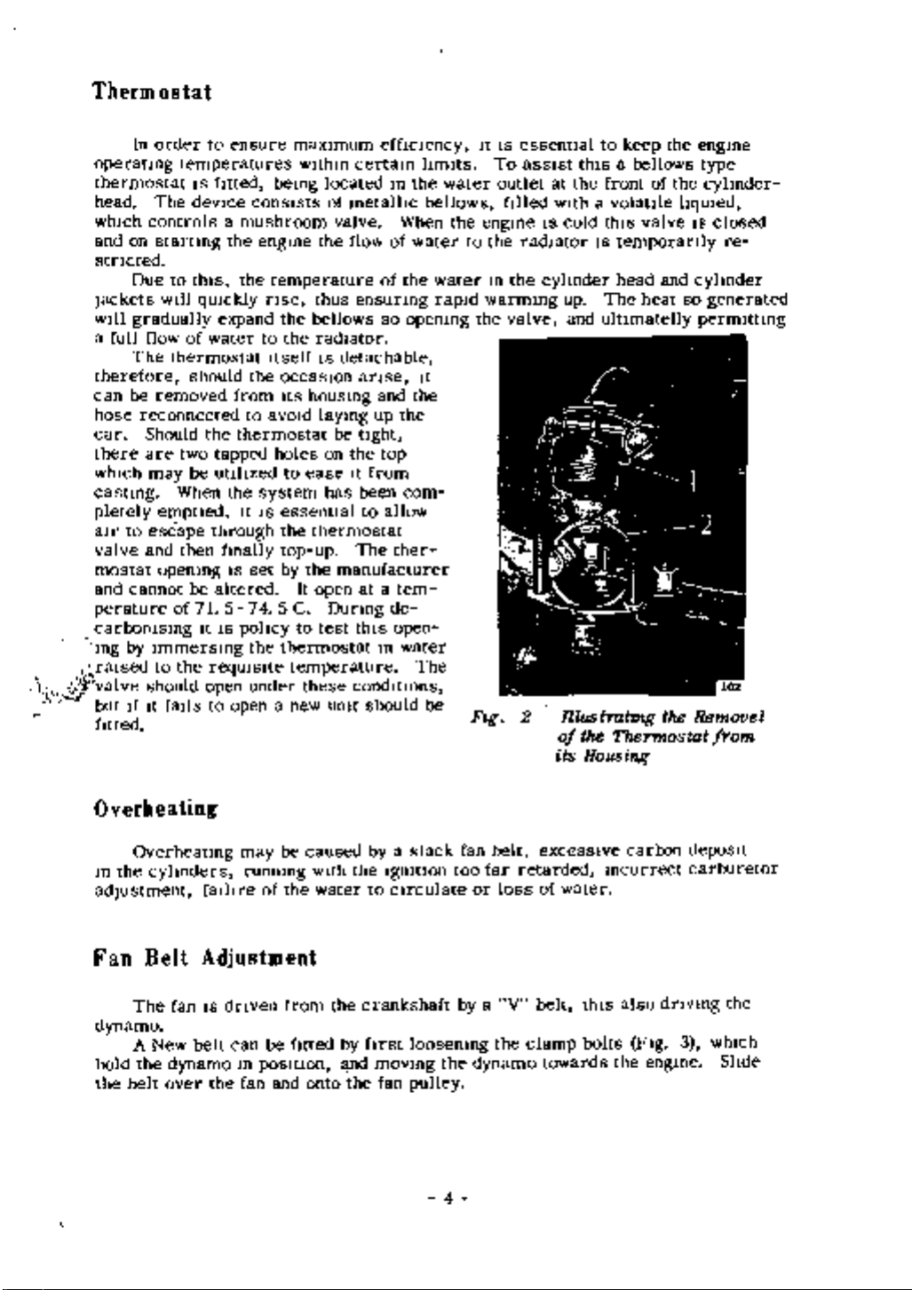
nlus
tTahng
the
of
its
Thermostat
Housing
bellows
valve
heat
it
0
of
t
the
the
hqUled
and
the
engine
type
cyhnder
IS
closed
cyhnder
so
generated
permitting
I
2
c
Remove
from
re
l
l
Overheating
Overheating
the
In
cyhnders
adjustment
Fan
Belt
fan
The
dynamo
hold
the
A
belt
the
New
dynamo
over
may
runmng
falhre
of
Adjustment
dnven
IS
can
m
fan
be
posltJon
belt
the
and
be
the
from
fitted
caused
WIth
water
the
onto
the
crankshaft
by
l
lld
the
by
to
ftrst
moving
fan
a
slack
Igmtlon
CIrculate
loosemng
pulley
the
4
fan
too
or
by
dynamo
thIS
bolts
carbon
Incorrect
also
FIg
the
dnvlng
engine
depoSIt
carburetor
3
whIch
the
Shde
excessIve
belt
far
retarded
loss
of
water
a
V
belt
the
clamp
towards
Adjustment
dynamo
be
sufftclently
belt
should
between
when
As
pulleys
tight
the
dynamo
the
correct
the
lock
the
to
away
have
the
generator
mIdspan
the
dnve
It
IS
do
so
and
tensIOn
dynamo
from
not
IS
tight
15
IS
necessary
may
water
m
then
the
to
to
IS
pushed
taken
cause
has
pOSItiOn
made
engme
prevent
20
and
pump
been
rnm
crankshaft
ftrmly
the
on
to
excessIve
beanngs
obtamed
agam
by
bnngmg
The
shp
5 8 3
V
have
belt
yet
pulley
of
the fan
wear
the
should
the
4
slack
the
belt
to
After
securely
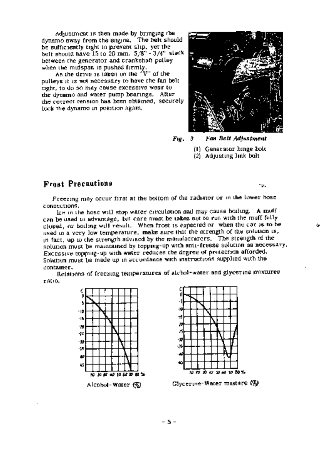
FIg
3
Fan
I
Generator
2
AdJustmg
Belt
Adjustment
bolt
hmge
lmk
bolt
Frost
Freezmg
connections
Ice
be
can
closed
used
m
fact
solution
ExcessIve
Solution
contamer
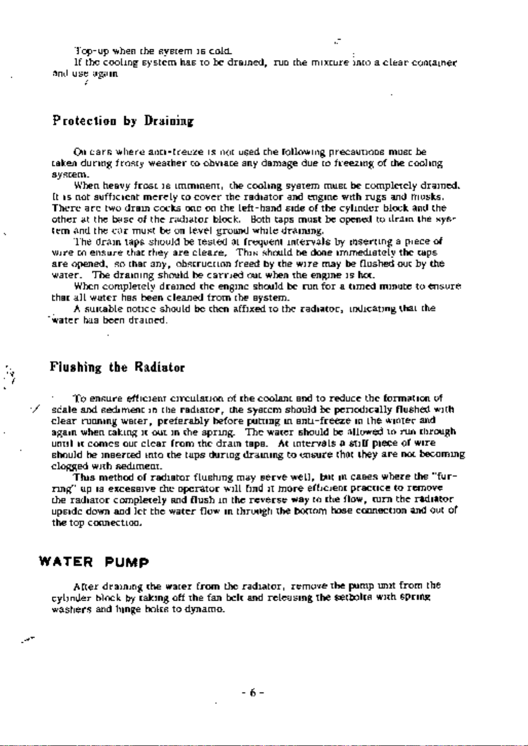
Relations
ratIO
Precautions
m
the
used
or
bOlhng
a
m
very
to
up
must
toppmg
must
may
hose
to
advantage
low
the
be
be
of
c
o
5
10
15
lD
IS
31
35
III
45
Alcohol
occur
wIll
wIll
temperature
strength
mamtamed
up
made
freezmg
lOYJ
10
ftrst at
stop
result
with
up
1
4Q
50
Water
the
water
but
care
When
adVIsed
toppmg
by
water
m
accordance
temperatures
a1
601lI
ro
bottom
cIrculation
must
make
by
reduces
be
frost
sure
the
manufacturers
up
WIth
of
the
of
taken
IS
expected
that
WIth
the
degree
mstructlons
alchol
c
o
5
10
i5
ID
15
JO
J5
41
45
Glycenne
and
anti
radIator
may
not
the
freeze
water
10 20 30
cause
to
run
or
strength
of
protection
and
1
40 50 60
Water
or
m
bOllmg
wIth
when
of
The
strength
solution
supphed
glycenne
1
70
mIxture
the
the
the
lower
the
afforded
WIth
80
muff
car
solution
as
necessary
mIxtures
ro
0
hose
A
muff
fully
to
be
IS
IS
of
the
the
5
and
Top
If
use
the
up
agam
when
coolmg
the
system
system
has
IS
cold
be
dramed
to
run
the
mIxture
mto a
clear
contamer
Protection
On
taken
dunng
cars
by
where
frosty
Draining
antI
freeze
weather
IS
not
to
obvIate
used
any
the
followmg
damage
due
precautions
to
freezmg
must
be
the
of
coohng
system
When
not
suffIcient
are two
the
at
and
the
The
to
ensure
opened
The
When
all
water
A
SUItable
has
To
ensure
and
runnmg
when
It
comes
be
with
Tlus
up
down
connectIon
heavy
dram
completely
been
sedIment
mserted
rnethod
is
It IS
There
other
tem
wIre
are
water
that
water
I
Flushing
scale
clear
agam
untIl
should
clogged
rlOg
the
radIator
upSIde
the
top
frost
dram
base
of
car
must
taps
that
that
so
drammg
has
notice
dramed
the
Radiator
effICIent
water
takmg
out
sedIment
of
excessIve
completely
and
let
merely
cocks
the
should
they
any
been
m
preferably
It
out
clear
mto
radiator
the
IS
radiator
be
are
should
dramed
cleaned
should
CIrculatIon
the
m
from
the
the
and
water
Immment
to
cover
one
on
level
be
cleare
obstruction
be
be
radIator
the
taps
flushmg
operator
flush
the
on
block
ground
tested
carned
the
engme
from
then affIxed
before
spnng
the
dralO
durmg
m
flow
the
coohng
the
radiator
left
at
frequent
Tlus
freed
out
the
the
of
the
system
puttmg
The
taps
drammg
may
Will find
the
m
through
hand
Both
while
should
system
coolant
serve
reverse
taps
should
by
when
to
water
it
system
and
SIde
drammg
mtervals
be
the
wIre
the
be
the
and
should
m
antI
At
mtervals
to
well
more
way
bottom
the
engme
of
must
done
engme
run
radIator
to
should
ensure
effiCIent
to
must
wIth
the
cyhnder
be
opened
by
immedIately
be flushed
may
IS
for
a
reduce
be
pencxhcally
freeze
be
a
that
but
m cases
the
flow
hose
be
completely
rugs
to
lOsertlng
hot
tImed
mdIcatlng
thefonnatIon
the
m
allowed
stIff
pIece
they
practIce
turn
connectIon
block
dram
mmute
wlOter
to
are
where
and
a
the
out
that
flushed
run
to
the
pIece
of
not
musks
and
Wire
the
remove
radIator
and
dramed
the
the
sys
of
taps
the
by
to
ensure
the
of
With
and
through
becommg
fur
out
of
4
WATER
cylInder
washers
After
PUMP
drammg
block
and
by
hmge
the
takmg
bolts
water
off
to
dynamo
the
from
fan
the
belt
radIator
and
6
remove
releasmg
the
the
setbolts
pump
unIt
WIth
from
spnnp
the
WATER
PUMP
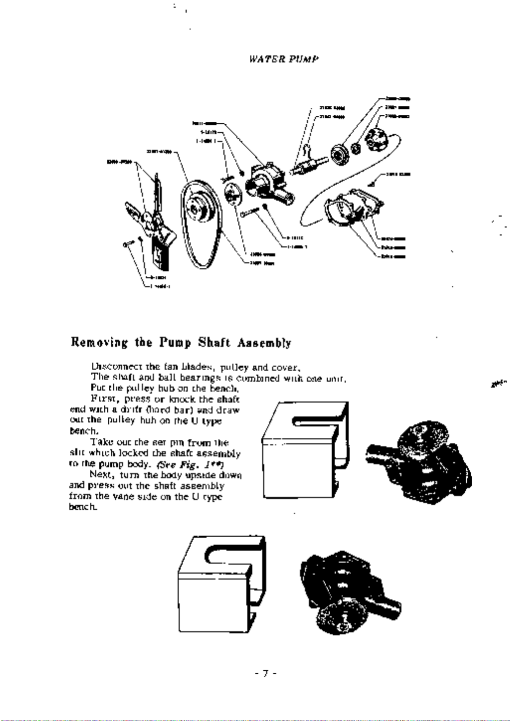
Removing
DIsconnect
The
the
Put
FIrst
end
WIth
out
the
the
pulley
Take
whIch
pump
Next
press
the
bench
sht
to
and
from
bench
shaft
a
out
out
vane
pulley
press
dnft
locked
body
turn
the
the
the
and
hub
SIde
the
hard
the
the
Pump
fan
ball
hub
or
on
set
See
body
shaft
on
blades
beanngs
on
knock
bar
the
pm
shaft
Fig
upsIde
assembly
the
Shaft
the
the
and
U
type
from
assembly
1
U
type
pulley
bench
shaft
draw
the
down
Assembly
IS
combmed
and
cover
with
one
umt
ji
7
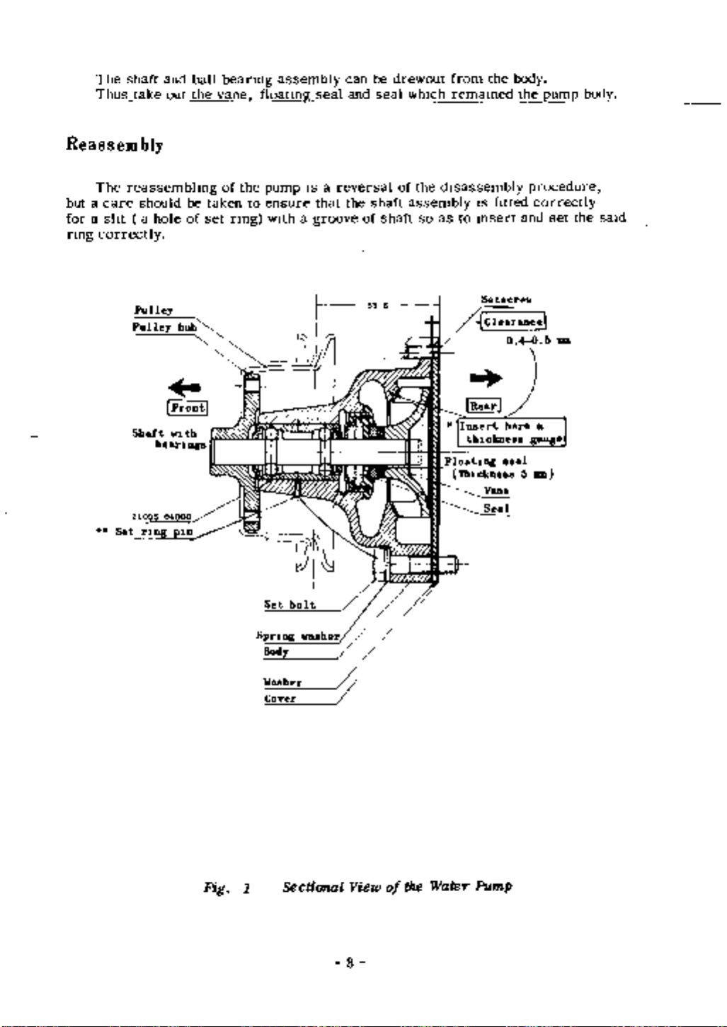
The
Thus
shaft
take
and
out
ball
the
beanng
vane
assembly
floatmg
seal
can
and
be
seal
drewout
whIch
from
remamed
the
body
the
pump
body
Reassem
The
but
a
care
foraslIt
nng
correctly
Set
bly
reassembhng
should
a
Pulley
Pulley
Shaft
rlDg
hole
WJ th
bearIngs
21035OOO
plD
be
of
hub
taken
set
pump
ensure
wIth
IS
a
a
that
groove
reversal
the
of
the
to
nng
of
shaft
shaft
of
the
assembly
so as
disassembly
IS
fItted
to
msert
procedure
correctly
and
set
the
saId
Fig
1
Set
SPrIng
Body
Washer
Cover
t
bol
washer
Sectional
View
8
the
of
Water
Pump
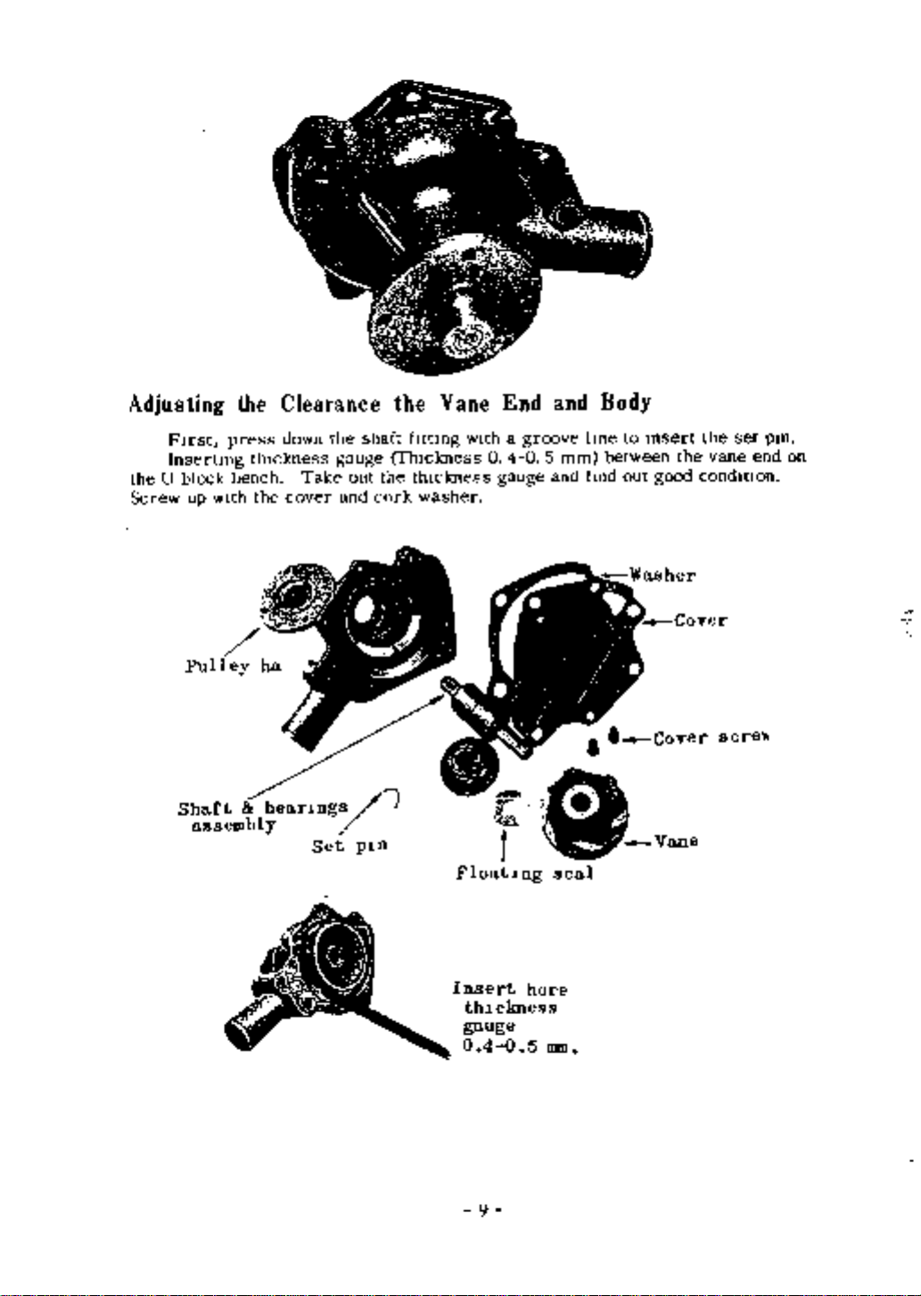
Adjusting
FIrst
Insertmg
the
U
block
Screw
up
wIth
the
press
bench
Clearance
thIckness
the
down
cover
Take
the
gauge
and
out
shaft
cork
the
fIttmg
fhlckness
the
thickness
washer
Vane
wIth
O40 5
End
a
gauge
groove
and
mm
and
Body
lme
fmd
to
between
out
msert
good
the
the
set
vane
condmon
end
pm
on
sere
Shaft
assembly
bear1llgs
Set
p1ll
Floa
Insert
thl
ga
0
uge
9
Y
f
tl
ckness
40
llg
here
5
0
seal
mm
Vane
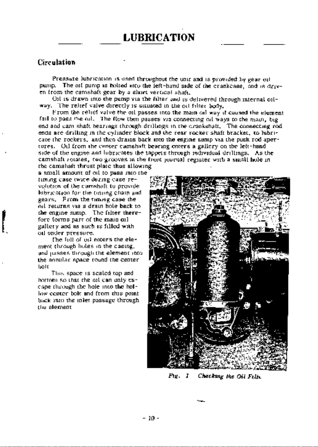
Circulation
LUBRICA
TION
Pressure
pump
en
from
OllIS
The
way
From
fml
to
and
end
ends
are
the
cate
tures
sIde
of
camshaft
the
camshaft
a
small
tlmmg
volution
lubncatlOn
gears
011
returns
the
engme
fore
forms
gallery
under
oJ
The
ment
through
and
passes
the
annular
bolt
ThIs
bottom
cape
through
center
low
back
Into
the
element
The
011
the
camshaft
drawn
rehef
the
rhe
pass
cam
dnlhng
rockers
from
all
the
engme
rotates
amount
case tWIce
of
the
for
From
VIa
sump
part
and
as
pressure
full
of
through
space
space
that
so
bolt
the
lubncatlon
pump
rehef
011
shaft
thrust
of
camshaft
the
the
a
of
such
011
holes
IS
the
the
and
mlet
mto
valve
beanngs
m
the
and
the
center
and
two
plate
011
dunng
tlmmg
tlmmg
dram
The
the
IS
enters
m
the
round
sealed
011
hole
from
passage
IS
gear
the
dIrectly
valve
The
cyhnder
then
lubncates
grooves
to
hole
ftlter
mam
fIlled
the
element
can
mto
IS
bolted
pump
flow
thus
pass
case
to
cham
case
the
casmg
the
top
only
the
thIS
used
mto
a
by
the
011
then
through
drams
camshaft
m
allowmg
mto
re
provIde
the
back
there
oJ
with
ele
center
and
es
hol
pomt
through
throughout
the
short
the
vIa
IS
situated
passes
passes
dnllmgs
block
back
the
tappets
the
the
and
to
mto
left
vertical
filter
Into
and
Into
beanng
front
the
hand
and
m
the
the
vIa
connectmg
m
the
rear
the
enters
through
Journal
umt
shaft
the
engme
sIde
IS
011
mam
crankshaft
rocker
regIster
and
of
dehvered
filter
011
sump
a
gallery
mdlvldual
IS
the
body
way
011
shaft
provIded
crankcase
through
If
caused
ways
The
bracket
the
vIa
on
the
dnlhngs
WIth
a
by
to
the
connectmg
push
left
small
gear
and
mternal
the
mam
rod
hole
to
hand
As
011
IS
dnv
011
element
lubn
aper
the
m
bIg
rod
Flg
1
Checkmg
the
Oil
FlUt
10
Draining
the
Sump
Oil
Pan
The
One
011
new
with
never
are
mam
Oil
pressure
to
run
Refillig
sump
new
after
Dram
It
any
Never
to
contammate
Pressure
The
normal
The
warmng
drops
the
a
IS
and
reconditiOned
the
first
the
011
when
sludge
use
petrol
completely
operatmg
below
engme
or
metal
or
lIght
pressmg
1000
the
sediment
or
paraffm
dIspersed
fresh
any
whIch
8
lbs
serIOus
km
engme
OIl
pressure
IS
sq
damage
engmes
and
IS
whIch
for
from
Oll
emboclted
m
the
the
dram
sump
with
subsequently
hot
smce
have accumulatted
may
flushmg
the
engme
ThIs
may
IS
60
10
the
under
these
result
may
must
at
warm
purposes
lubncatiOn
cause
lb
per
mstrument
plug
be
mtervals
Oil
premature
sq
cIrcumstances
flows
m
dramed
Such
of
freely
cleamng
system
panel
and
5000
beanng
hght
do
and
and
not
refilled
km
medlUms
faIlure
If
takes
wIll
the
attempt
with
re
Oil
from
the
as
pOSSIble
the
reach
Check
If
up
off
with
Side
When
the
engme
Before
readmg
to
Check
nece
and
ascertam
sludge
of
the
refllltng
fIller
sump
for
the
sal
Oil
testing
Always
It
Low
v
ale
orifIce
before
level
pump
should
If
that
that
the
and mIslead
the
WIpe
readmg
Oil
of
the
the
no
bemg
sump
level
be
remembered
Pressure
m
OIl
warnmg
gauge
aIr
defectIve
do
of
the
the
leakage
the
dIp
the
not
Oil
stick
dIpstick
engme
Itgiit
stramer
pour
the
IS
eXIsts
remove
the
operator
ensure
clean
that
sump
still
m
11
the
time
at
OIl
m
too
qUIckly
as
the
to
quantity
must
means
strainer
umt
the
a
non
IS
vehIcle
fluffy
be
allowed
of
reftllmg
clean
and
rectify
the
uniOn
that
wIth
by
on
after
ump
the
the
dip
the
and
IS
as
cloth
as
on
the
It
of
for
stIck
sump
not
may
lubricant
near
before
new
choked
the
fault
overflow
level
011
and
switch
suction
10
talang
to
top
rr
J
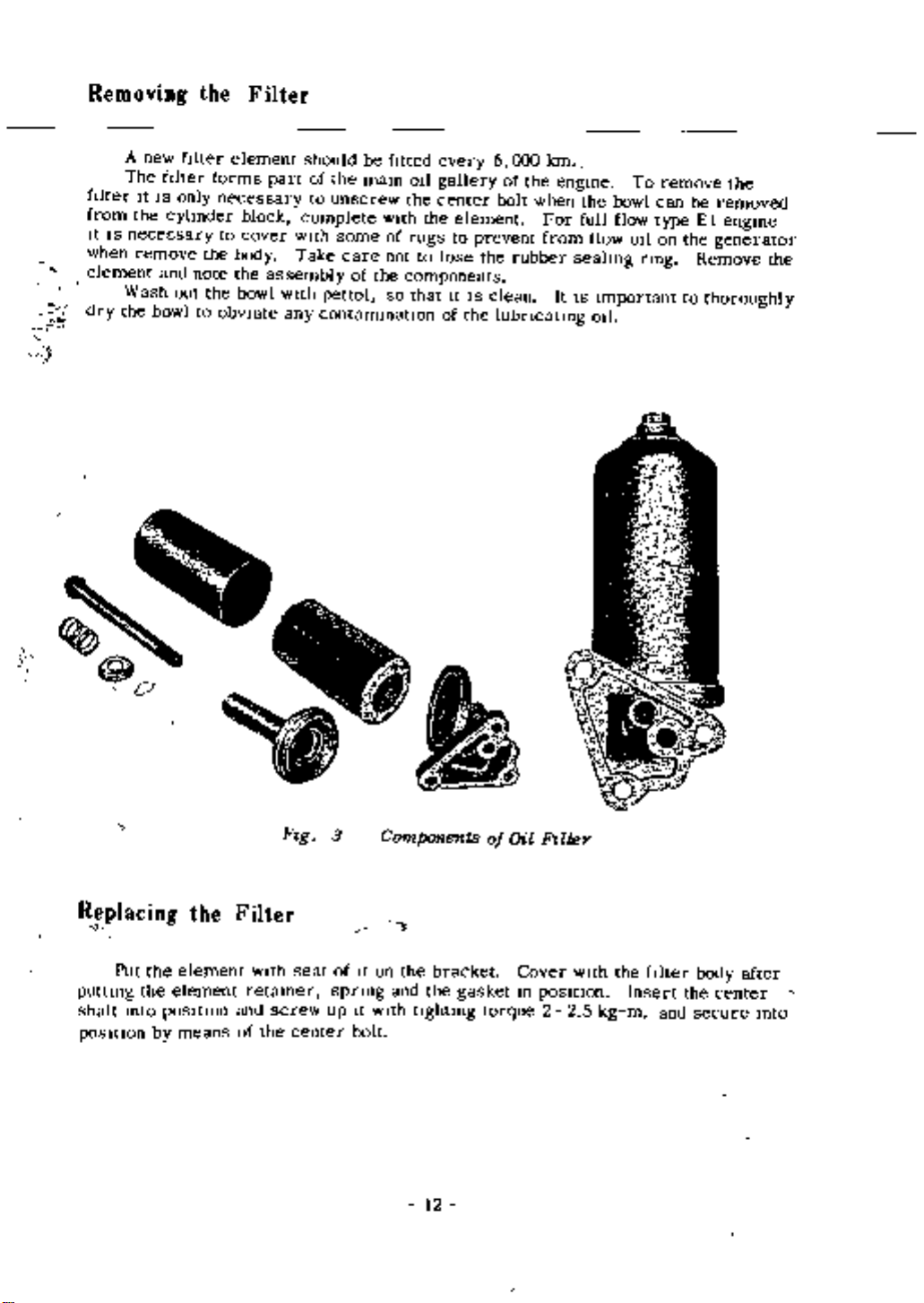
Removing
A
new
The
hlter
It
IS
from
the
ItISneceE
when
remove
element
Wash
the
dry
bowl
the
hlter
fIlter
only
cylinder
sary
and
note
out
to
element
forms
necessary
to
the
the
obVIate
Filter
block
cover
body
the
bowl
should
of
part
to
complete
wIth
Take
assembly
WIth
any
be
the
mam
unscrew
some
care
of
pettol
contammatIon
fitted
wIth
of
not
the
so
every
011
gallery
the
center
the
element
to
rugs
lose
to
components
It
that
of
6
bolt
prevent
the
IS
clean
the
lubncatmg
000
of
rubber
the
km
when
For
from
engme
full
seahng
It
IS
the
flow
Important
011
bowl
flow
To
011
nng
remove
can
type
on
be
removed
E1
the
generator
Remove
to
thoroughly
the
engme
the
Replacing
4
the
Put
puttmg
shaft
posttJon
the
mto
by
the
element
element
posltlon
means
Filter
WIth
retamer
and
of
the
Flg
screw
seat
center
3
of
spnng
up
It
bolt
Components
the
It
on
and
with
bracket
the
ughtmg
12
of
gasket
torque
Oil
Cover
10
Rlter
posltlon
2
2
with
the
filter
Insert
5
m
kg
the
and
body
secure
after
center
mto
Removing
The
Remove
OIl
flange
pan
cunng
the
process
moviDg
WIth
011ISdrawn
the
011
pIck
The
hvery
pipe
Notice
correctly
Removing
sump
the
stramer
when
the
0
the
from
the
sump
mto
up
flange
that
the
Oil
capacIty
set screw
and
the
Strainer
the
the
to
may
bolts
there
reftttmg
Oil
the
engme
lowered
011
pump
are
Pan
IS
lower
pump
be
dIsmantled
the
Pump
3
bolts
J
and
1
htres
bolts
takmg
It
IS
unscrew
dowel
whIch
from
care
possIble
To
remove
pinS
Dram
for
are
the
not
to
the
cleamng
to
the
mserted
bottom
to
remove
the
secunng
the
011
edge
damage
stramer
purpose
cover
and
from
the
the
bolts
whICh
replace
the
of
the
Jomt
OIl
stramer
unto
by
must
the
undersIde
bell
washers
the
umon
removing
dram
housmg
through
be
posItIOned
plug
of
the
m
the
connecting
the
de
se
Lower
whIch
i
l
t
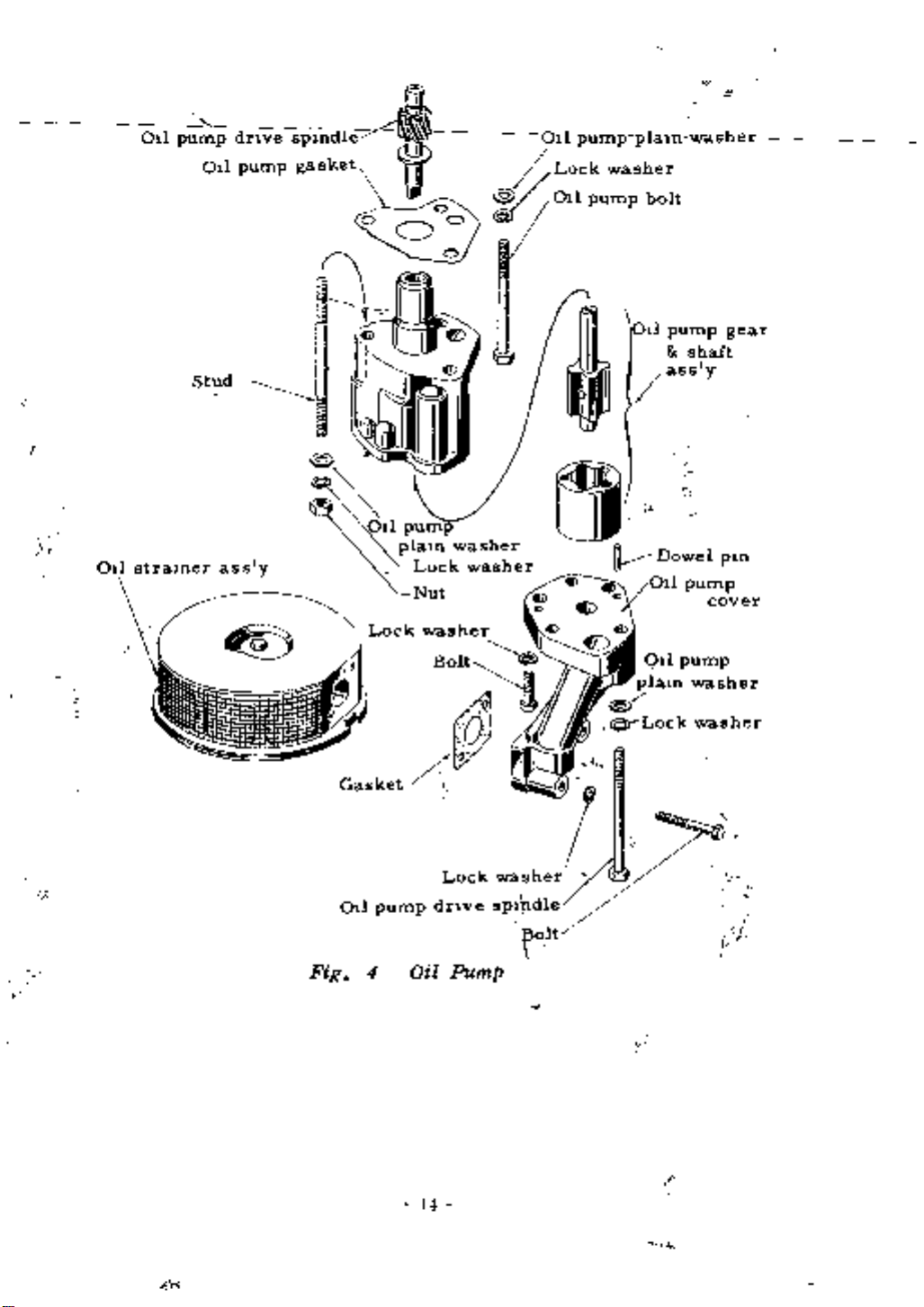
Remove
OIl
FIg
the
pump
pump
4
Illustrates
bottom
with
Dismantling
Remove
and
take
off
shaft
dnve
Refitting
the
of
the
to
matenal
washer
Smear
Into
Clean
positIOn
paraffm
011
pan
can
the
out
faces
Reassembling
the
the
the
and
the
the
and
Examme
be
and
ItS
the
cover
before
used
011
pan
cover
the
dnve
setscrews
the
Sump
sump
crank
again
of
the
Insert
the
are
pump
Oil
outer
reflttmg
the
JOint
and
shaft
Pump
On
by
case
JOint
If
the
Oil
pIck
long
In
explosed
and
tlltmg
rotor
washing
the
JOint
washer
It
IS
WIth
setscrews
Pump
strainer
up
enough
spnng
the
wIth
It
OIl
faces
sound
grease
to secure
washers
body
shde
In
pan
and
Into
form
out
paraffin
to
and
renew
but
and
the
Three
Unscrew
upSide
the
remove
It
IS
ftt
flange
the
whIch
down
the
engme
If
It
adVIsable
the
of
pump
secure
care
any
necessary
JOint
tlghtlng
the
the
the
Pay
washer
ftve
to
long
Inner
to
traces
to
bolts
the
crankcase
bolts
the
cover
rotor
remove
patlcular
of
The
ftt
a
new
Lift
them
old
up
secunng
and
to
with
any
attentIOn
Jomtlng
old
one
the
evenly
remove
the
traces
JOint
OIl
the
b6dy
ItS
pan
tills
result
the
The
chamfer
In
body
outer
the
and
rotor
be towards
cover
brmg
FIg
IS
tightened
the
rotors
the
slotted
ItISof
to
assemble
end
great
of
Importance
In
the
thIS
dnve
4
has
a
base
Into
of
down
chamfered
the
Insert
mesh
body
edge
ftlure
the
way
shaft
that
Will
Into
13
Oil
pump
dnve
spmdle
01l
Lock
Oil
pump
pump
washer
plaln
bolt
washer
Oil
strainer
Oil
pump
ass
I
gear
shaft
y
eJ
Dowel
ass
y
V
Oil
l
D
pin
pump
cover
Fig
f
f
i
4
Oil
Pump
14
a
Removing
SERVICE
Starting
ENGINE
Nut
and
OPERATIONS
IN
POSITION
Pulley
WITH
Remove
fan
belt
Bend
dog
A few
Pull
nut
off
mg
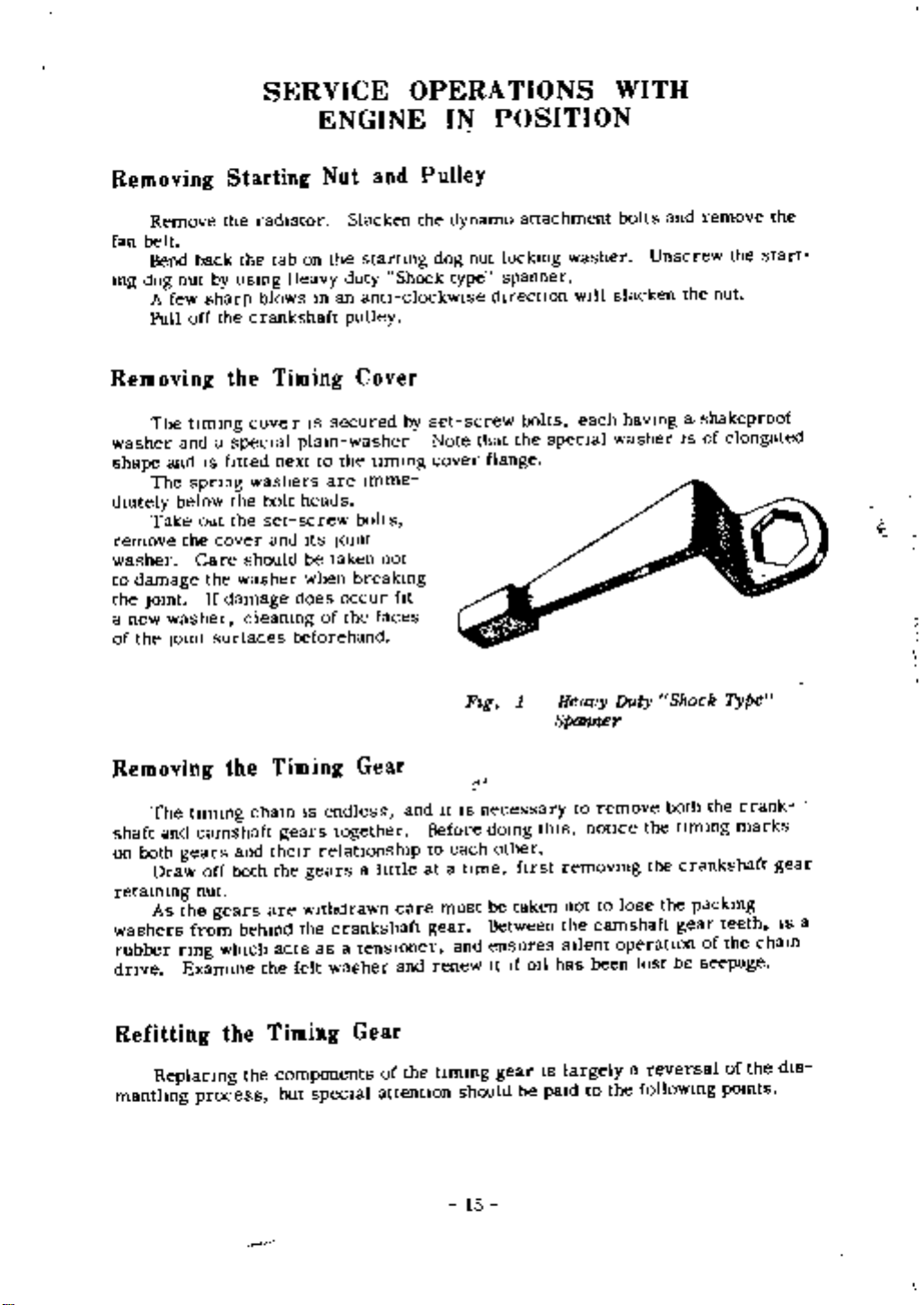
Removing
The
tImmg
washer
shape
dIately
remove
washer
to
the
a new
of
and
The
below
Take
damage
Jomt
washer
the
JOint
and
spnng
the
back
sharp
IS
out
Care
the
If
the
by
usmg
the
the
a
special
f1tted
the
the
cover
washer
damage
cleanmg
surfaces
radIator
the
tab
blows
crankshaft
Timing
cove
next
washers
bolt
set
and
should
on
Heavy
m
r
IS
plam
to
are
heads
screw
Its
be
taken
when
does
of
beforehand
Slacken
the
startmg
Shock
duty
an
ant1
clockwlse d1reCtIOn
pulley
Cover
secured
washer Note
the
Jomt
occur
the
by
tImmg
Imme
bolts
not
breakmg
fit
faces
the
set
cover
dynamo
dog
type
Fag
nut
screw
that
flange
attachment
lockmg
spanner
bolts
the
1
washer
WIll
each
specIal
Heavy
Spanner
and
bolts
slacken
Unscrew
the
remove
the
nut
havmgashakeproof
washer
Duty
IS
Shock
of
elongated
Type
the
start
t
Removing
The
shaft
and
on
both
gears
Draw
retaining
As
the
washers
rubber
dnve
from
nng
Examme
Refitting
ReplaCing
mantlmg
tImmg
camshaft
off
nut
gears
Wh1Ch
the
process
the
and
both
behind
the
Timing
cham
gears
theIr
the
are
acts
the
Timing
components
but
IS
endless
together
relatIonshIp
gears
w1thdrawn
the
crankshaft
as
felt
washer
spec1al
a
tenslOner
Gear
Gear
a
httle
of
attentlon
care
and
the
and
It
Before
to
at a
must
gear
renew
tlmmg
1S
each
t1me
and
should
15
JI
necessary
domg
other
be
Between
ensures
It
gear
taken
If
hrst
be
011
thIS
has
1S
pa1d
to
notIce
removmg
not
the
camshaft
SIlent
been
largely
to
remove
to
operatIon
the
the
the
lose
lost
a
reversal
follOWing
both
tImmg
the
gear
be
the
crankshaft
packmg
of
seepage
marks
teeth
the
of
pomts
crank
the
gear
IS a
cham
dIS
FIt
the
tlmmg
Turn
WIth
Its
Place
the
on
and
other
The
must
be
alIgnment
adjust
FIt
wards
the
crankshaft
marks
the
engme
are
and
opposIte
crankshaft
keywaymapproximately
shafts
mime
same
replaced
the
the
the
the
of
the
alIgnment
011
front
gears
Ensure
number
thrower
of
unless
gear
Dnve
the
mto
It
that
of
faces
Will
car
pOSitIOn
the
packmg
a
behmd
camshaft
the
gears
new
and
be
necessary
and
and
mime
until
the
ensunng
tJmmg
home
washers
crank
measuremg
the
crankshaft
check
gears
the
one
marks
or
that
mto
keyway
0
clock
that
taken
camshaft
the
to
vary
the
theIr
IS
posJtJon
the
the
on
from
alIgnment
the
gear
felt
at
keys
gears
has
so
washer
respective
T
D C
behmd
been
number
that
and
are
present
are
opposite
the
fitted
wIthafeeler
of
packmg
Its
concave
IS
In
posJtJon
shafts
the
m
crankshaft
In
thIs
Ensure
camshaft
keyways
each
to
gauge
washers
face
case
It
gear
the
To
to
Valve
Rocker
Remove
brackets
Removing
Dram
the
for
the
flUId
It IS
If
the
to
necessary
four
cylmder
find
because
water
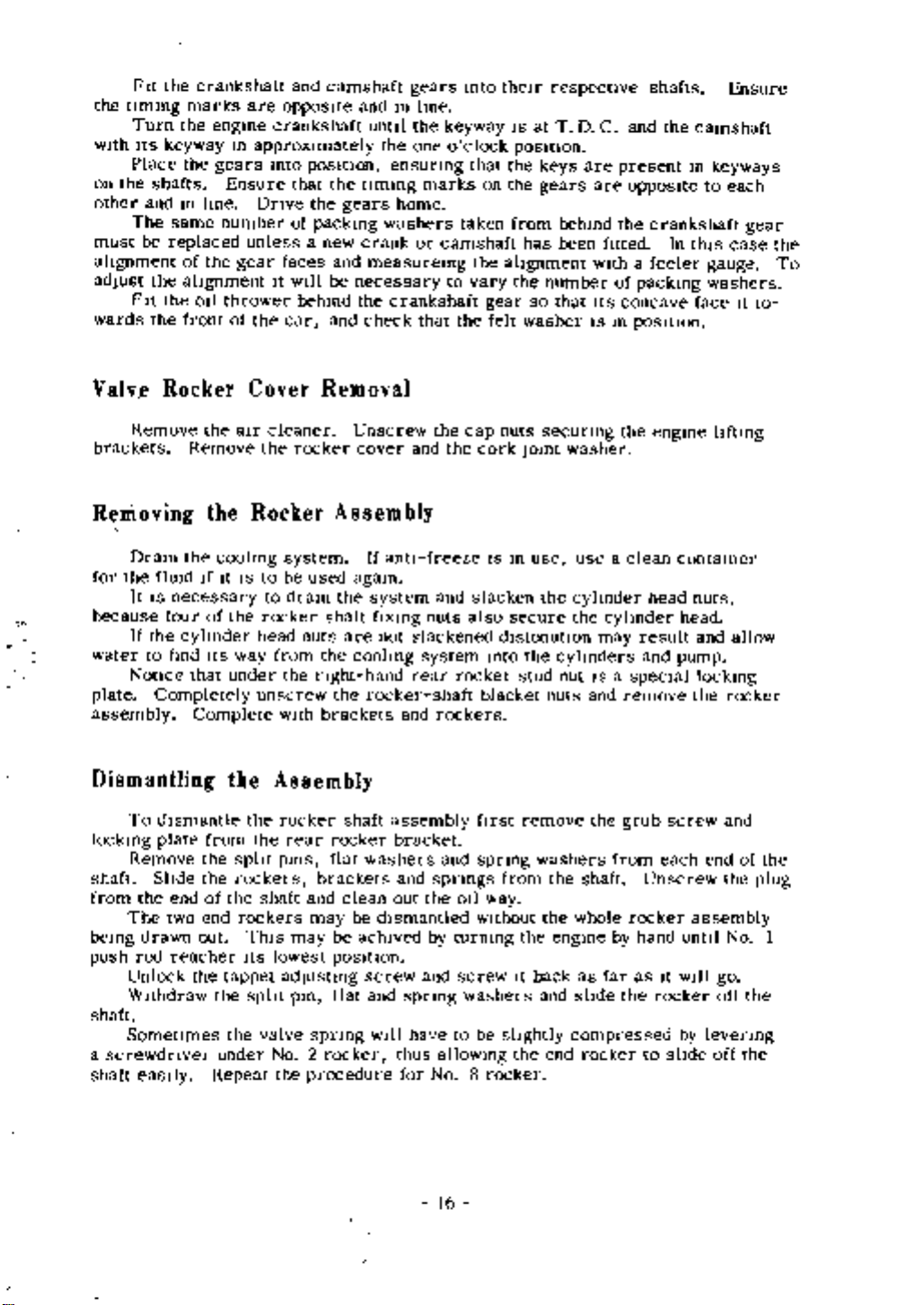
Notice
plate
Completely
assembly
Dismantling
To
dIsmantle
lockmg
shaft
from
bemg
push
shaft
a
shaft
Remove
SlIde
the
The
drawn
rod
Unlock
Withdraw
Sometimes
screwdnvel
eaSily
plate
end
two
reacher
the
aIr
Remove
the
coolmg
If
It
IS
of
the
ItS
way
that
under
Complete
the
from
the
split
the
rockers
of
the
end
rockers
out
the
tappet
the
the
under
Repeat
Cover
cleaner
the
Rocker
system
to
be
dram
to
rocker
head
from
the
unscrew
with
Assembly
the
rocker
the
rear
pms
shaft
ThIS
may
Its
lowest
adJustmg
split
pm
valve
No
the
Removal
rocker
Assembly
used
the
shaft
nuts
the
nght
the
brackets
rocker
flat
brackets
and
may
be
pOSItIOn
flat
spnng
2
rocker
procedure
Unscrew
cover
If
agam
are
coolmg
hand
rocker
shaft
washers
clean
be
achlved
screw
and
anti
system
ftxmg
not
rear
and
assembly
bracket
and
out
dIsmantled
spnng
have
WIll
thus
for
the
the
and
freeze
and
nuts
slackened
system
shaft
rockers
and
spnngs
the
by
and
allOWing
No
cap
slacken
also
rocker
ftrst
spnng
OIl
without
turmng
screw
washers
to
be
8
nuts
cork
IS
dlstonatlOn
mto
blacket
from
way
slIghtly
rocker
Jomt
m
secure
the
stud
remove
the
It
the
secunng
washer
use use
the
cylmder
the
cylmders
nut
nuts
washers
the
the
whole
engme
back
as
and
slide the
compressed
end
may
IS a
and
the
shaft
rocker
the
a
clean
cylmder
result
and
speCIal
remove
grub
from
Unscrew
rocker
hand
by
far
as
to
engme
head
screw
each
It
rocker
slIde
IIftmg
contamer
nuts
head
and
pump
lockmg
the
end
assembly
untIl
WIll
go
off
by
levenng
off
allow
rocker
and
the
No
of
the
plug
I
the
the
16
Fr
2
g
Reassembling
Rear
the
Locking
Rocker
Plate
1
Plate
2
Locatmg
Stud
On
workmg
of
No
2
repeating
completely
and
the
The
ends
of
lock
plate
Replace
shaft
front
of
that
the
cover
gasket
otherwIse
Push
If
the
for
IS
the
WIthout
Remove
Slacken
screwdnver
reassembly
dIagonally
left
of
the
process
stnpped
bushes
rockers
the
shaft
the
Replace
the
engme
rubber
or
OIl
leaks
Rod
Removal
valve
push
detaclung
the
all
with
No
reamed
and
spnng
the
bushed
the
rocker
rods
the
aIr
the
tIghten
from
3
and
until
down
down
spnng
Remember
and
rocker
Secure
and
rubber
will
assembly
to
be
rocker
cleaner
tappet
the
rocker
the
nut
to
so
on
they
and
to sIze
must
flat
cover
the
engme
bushes
result
hfted
assembly
and
adJustmg
pedestal
nut
returmng
are
rebushed
be
to
replace
washers
and
cover
hftlng
has
out
rocker
shaft
left
all
before
replaced
gasket
are
already
They
screws
as
by
found
a
bracket
nut
tight
the
the
wIth
means
plates
cover
fulcrum
of
No
from
If
OIl
assembly
m
rocker
the
The
are
be
to
been
on
may
their
to
secunng
1
the
the
holes
theIr
spht
vent
of
the
faulty
removed
the
depress
nuts a httle at a
pedestal
left
nut
rocker
wIll
have
on
the
ongmal
shaft
locating
pms
pIpe
two
cap
m
positIOn
they
other
full
extent
the
bracket
of
No
assembly
to
shaft
pOSJtJon
on
the
should
nuts
If
must
all
that
hand
then
valve
4
be
screw
ends
the
be
bracket
has
rednlled
be
ensunng
be
remams
taken
usmg
sprmg
nght
on
and
of
the
at
rocker
renewed
time
nut
and
been
the
the
out
a
17
sltde
All
withdrawn
push
wards
the
rocker
but the
rods
ensure
reassembly
after
end
sIde
the
that
ways
push
removal
IS a
the
and
rods
of
ball
straIght
can
ends
Itft
the
out
be
two
regIster
forward
the
withdrawn
end
push
rockers
In
reversal
the
rod
In
thIs
from
tappet
of
the
way
the
cups
dIsmantling
These
shaft
From
wIll
When
have
here
process
to
be
replacing
on
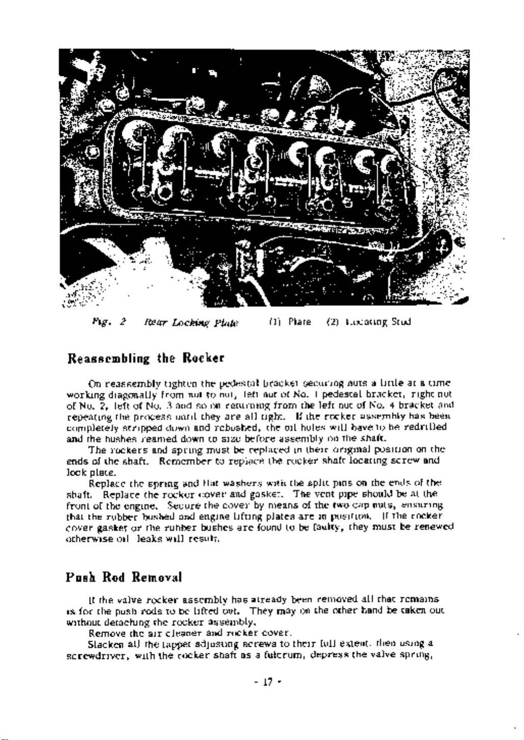
Adjusting
Remove
There
rocker
portant
dIsperse
WIll
the
and
to
result
Turn
valve
the
the
IS
should
the
maintain
In
fully
Valve
the
base
fIlm
a
wrong
engine
aIr
be
of
closed
Rocker
cleaner
a
clearance
of
the
pressure
011
reading
over
from
valve
by
and
wIth
the
hand
Clt
rocker
of
stem
push
being
arances
O
014
a
screw
rod
taken
Starting
cover
In
Whtlst
cup
dnver
handle
0
3S
mm
checking
on
Fallure
untll
the
fbetween
the
clearances
tappet
to
follow
the
push
the
adjusting
thIs
rod
face
of
IS
It
screw
procedure
stops
falling
the
lm
to
Fig
3
Adjusting
the
18
Rocker
Clearance
 Loading...