

Page 1
PORTABLE RADIO
OPERATOR MANUAL
Datron World Communications
3030 Enterprice Ct
Vista CA, 92081
Phone: 760-597-1500
Fax: 760-597-1510
www.dtwc.com
Page 2

IMPORTANT
Please read all instructions included in this owner’s manual before using the transceiver
This manual contains important information for the Guardian GII portable series radios
and should be saved for future reference.
ABOUT APCO 25
This device is made under license under one or more of the following US Patents:
4590473, 4636791, 4833701, 4972460, 5146497, 5148482, 5164986, 5185795, 5185796,
5164986, 5185796, 5271017, 5377229,
The AMBE+2 voice coding Technology embodied in this product is protected by
intellectual property rights including patent rights, copyrights and trade secrets of Digital
Voice Systems, Inc. This voice coding Technology is licensed solely for use within this
Communications Equipment. The user of this Technology is explicitly prohibited from
attempting to extract, remove, decompile, reverse engineer, or disassemble the Object
Code, or in any other way convert the Object Code into a human-readable form. U.S.
Patent Nos.: 6,912,495 B2, 6,199,037 B1, 5,870,405, 5,826,222, #5,754,974, 5,701,390,
5,715,365, 5,649,050, 5,630,011, 5,581,656, 5,517,511, 5,491,772, 5,247,579, #5,226,084
and 5,195,166
PRECAUTIONS
BEFORE USING YOUR PORTABLE 2-WAY RADIO READ THIS IMPORTANT RF
ENERGY AWARENESS AND CONTROL INFORMATION AND OPERATIONAL
INSTRUCTIONS TO ENSURE COMPLIANCE WITH THE FCC’S RF EXPOSURE
LIMITS
NOTICE: This radio is intended for use in occupational/controlled conditions, where
users have full knowledge of their exposure and can exercise control over their exposure
to meet FCC limits. This radio devise is NOT authorized for general population,
consumer, or any other use.
This 2-way radio uses electromagnetic energy in the radio frequency (RF) spectrum to
provide communications between two or more users over a distance. It uses radio
frequency (RF) energy or radio waves to send and receive calls. RF energy is one form
of electromagnetic energy, which when used improperly can cause biological damage.
Very high levels of x-rays, for example, can damage tissue and genetic material.
Experts in science, engineering, medicine, health and industry work with organizations to
develop standards for exposure to RF energy. These standards provide recommended
levels of RF exposure or both workers and the general public. These recommended RF
Page 3

exposure levels include substantial margins of protection. All 2-way radios marketed in
North America are designed, manufactured and tested to ensure they meet government
established RF exposure levels. In addition, manufacturers also recommend specific
operating instructions to users of 2-way radios. These instructions are important because
they inform users about RF energy exposure and provide simple instructions on how to
control it. Please refer to the following website for more information on what RF energy
exposure is and how to control your exposure to assure compliance with established RF
exposure limits.
www.fcc.gov/oet/rfsafety/rf-faqs.html
www.osha.gov/SLTC/radiofrequencyradiation/index.html
Federal Communications Commission Regulations
The FCC rules require manufacturers to comply with FCC RF energy exposure limits for
portable 2-way radios before they can be marketed in the US. When 2-way radios are
used as a consequence of employment, the FCC requires users to be fully aware of and
able to control their exposure to meet occupational requirements. Exposure awareness
can be facilitated by the use of a product label directing users to specific user awareness
information. Your Datron 2-way radio has a RF exposure product label. Also your
Datron user manual includes information and operating instructions required to control
your RF exposure to satisfy compliance requirements.
COMPLIANCE WITH RF EXPOSURE STANDARDS
Your Datron 2-way radio is designed and tested to comply with a number of national and
international standards and guidelines (listed below) for human exposure to radio
frequency electromagnetic energy. This radio compiles with IEEE and ICNIRP exposure
limits for occupational/controlled RF exposure environment at operating duty factors of
up to 50 % transmitting and is authorized by the FCC for occupational use only. In terms
of measuring RF energy for compliance with the FCC exposure guidelines, your radio
radiates measurable RF energy only while it is transmitting (during talking), not when it
is receiving (listening) or in standby mode. The approved batteries supplied with this
radio are rated at 5-5-90 duty factor (5% talk- 5% Listen 90% standby), even though this
radio complies with the FCC occupational RF exposure limits and may operate at duty
factors of up to 50 % talk.
Your Datron 2-way radio complies with the following RF energy exposure standards and
guidelines:
• United States Federal Communications Commission, Code of Federal
Regulations;47 CFR §§1.1307, 1.1310, 2.1091 and 2.1093
• American National Standards Institute (ANSI)/Institute of Electrical and
Electronic Engineers (IEEE) C95. 1-1992
• Institute of Electrical and Electronic Engineers (IEEE) C95. 1-1999 Edition
Page 4

RF EXPOSURE COMPLIANCE AND CONTROL GUIDELINES AND
OPERATING INSTRUCTIONS
To control your exposure and ensure compliance with occupational/controlled
environment exposure limits always adhere to the following procedures.
Guidelines:
• Do not remove the RF Exposure Label from the device.
• User awareness instructions should accompany device when transferred to other
users.
• Do not use this device if the operational requirements described herein are not
met.
Operating Instructions:
• Transmit no more than the rated duty factor of 50 % of the time. To transmit
(talk), push the Push-To-Talk (PTT) button. To receive calls, release the PTT
button. Transmitting 50 % of the time, or less, is important because this radio
generates measureable RF energy exposure only when transmitting (in terms of
measuring for standards compliance).
• Hold the radio in a vertical position in front of face with the microphone (and the
other parts of the radio, including the antenna) at least one inch (2.5 cm) away
from the nose. Keeping the radio at the proper distance is important because RF
exposure decreases with distance from the antenna. Antenna should be kept away
from the eyes.
• When worn on the body, always place the radio in a Datron approved clip, holder,
holster, or body harness for this product. Using approved body-worn accessories
is important because the use of Datron or other manufacturer’s non-approved
accessories may result in exposure levels, which exceed the FCC’s
occupational/controlled environmental RF exposure limits.
• If you are not using a body-worn accessory and are not using the radio in the
intended use position in front of the face, then ensure the antenna and the radio
are kept at least 1 inch (2.5 cm) from the body when transmitting. Keeping the
radio at the proper distance is important because RF exposure decreases with
increasing distance from the antenna.
• Use only Datron approved supplied or replacement antennas, batteries and
accessories. Use of non Datron approved antennas, batteries and accessories may
exceed the FCC exposure guidelines.
Page 5

• For a list of Datron approved accessories refer to the accessory section in this
manual or visit
www.dtwc.com.
Contact Information
For additional information on exposure requirements or other information contact Datron
Customer Service at 760-597-1500.
LIMITED WARRANTY AND REMEDIES
Page 6
1: INTRODUCTION
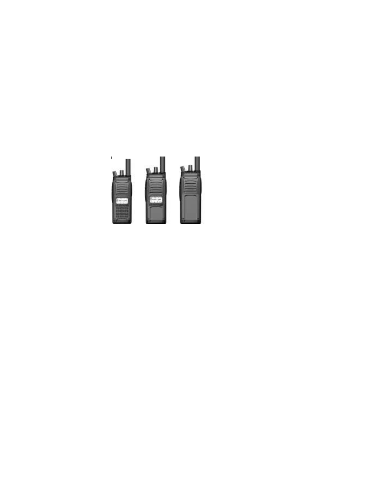
Guardian II Portable Radio
The Guardian II series portable radios are crafted with advanced electronics, software and
materials incorporated into a rugged, professional design offering years of reliable service. The
radios provide operation in analog or digital, wideband or narrowband modes, and are APCO
Project-25 compatible. The Guardian II is available in three separate models (pictured below)
allowing the radio to be customized to end user requirements. Numerous combinations of
options, features and channel settings are possible using the Guardian PC Programmer.
Standard features include:
•
1024-channels/ Talkgroups (64 zones of 16 channels/zone)
•
AES, DES OFB Encryption
•
P-25 Trunking
•
P-25 OTAR (Over the Air Rekey)
•
Backlit LCD
•
Tri-color LED status indicator
•
16-position rotary volume and channel knobs
•
Two programmable collar switches
•
Emergency and function buttons
Channels can be individually programmed for 25 kHz wideband or 12.5 kHz narrowband
operation, analog or digital, clear or encrypted, with transmitter power settable from .2W to 5W.
Up to eight shadow channels can be programmed for any channel providing all-mode radio
performance. Thirty two encryption keys can be stored in the radio.
Radio Configuration
A radio configuration includes channels, zones and banks.
Channels
Channels contain all the information required to transmit and receive. A channel is referred to as
primary when it is differentiated from a shadow channel. The standard radio has a total of 1024
programmable channels. Each channel can be set for: Receive and transmit frequencies
Wideband or narrowband
•
Page 7

•
Analog or digital
•
Various squelch types
•
Encryption key
•
Power output level
•
12-character alphanumeric channel tag (name)
Zones
Zones provide a way of rapidly switching groups of channels. Each zone can contain up to 16
channels. If the 3 position collar switch set for Zone Select, the radio provides easy access to 48
channels by using the collar switch and the channel select knob. Up to 64 zones can be accessed
from the radio keypad or programmable soft keys and displayed in the standard radio. Channels
can be mapped to the channel select knob within each zone using the PC Programmer. A zone
must be assigned to a bank.
Banks
Banks provide a way of switching a set of zones (containing channels) with a few key presses.
For example, the Banks can be programmed with different geographic frequency plans. Up to 8
banks (with a maximum of 16 zones each) can be programmed into the radio. Each bank contains
a collection of zones, as well as defined priority channels, a home channel, and an emergency
channel.
Shadow Channels
Shadow channels are created and edited using the PC Programmer. Up to 8 shadow channels are
available for each primary channel. Shadow channels enable you to monitor and reply (if all
settings match) to all transmissions on a given channel. Shadow channels can have different
modulation modes (analog or digital), bandwidths, squelch modes, digital network access codes
(NAC), or encryption keys than their associated primary channel. Each shadow channel must
have the same transmit and receive frequencies, scan list, talk-around, locked options, and
transmit power level as its associated primary channel. Shadow
channels count toward the 1024-
channel total radio capacity.
Accessories
The following accessories are available for the Guardian Portable radio. Contact your Guardian
representative for details on these accessories.
•
Rechargeable battery packs
•
Single and multi-unit rapid chargers
•
Antenna
•
PC Programming kit
•
Cloning cable
•
Audio Accessories
•
Speaker Microphone
•
Radio case and belt clip
Page 8

Options
The Guardian II portable radio supports add-on software options for solutions to communications
requirements such as P-25 Trunking and Encryption. Optional enhancements are discussed in the final
chapters of this manual.
The Guardian II Portable is covered by the limited warranty (see warranty statement)
Factory Support
For warranty service, contact:
Technical Support Services Group
Datron World Communications Division
3030 Enterprise Court
Vista, CA 92081
Phone: (760) 597-1500
E-mail: service@dtwc.com.
Before calling have the following information:
•
Radio model number, serial number, and date of installation.
•
Name of dealer or supplier of equipment.
•
Detailed explanation of suspected problem.
•
Return shipping instructions.
•
Telephone or fax number where buyer can be contacted.
Do not return a radio to the factory for service without first obtaining an RMA number from the
Technical Support Services Group.
User Servicing
No user serviceable parts are inside. This product is subject to electrostatic discharge (ESD)
damage. Specialized maintenance and repair procedures are required. Unsuccessful attempts to
repair this product can void the warranty. This product requires customer-specific programming
to function as required. Radio programming is performed using a computer and authorized
software. The factory does not have knowledge of customer-specific programming. Government
agency users should contact their authorized personnel for assistance regarding the correct
operation of this product.
Page 9

2: RADIO CONTROLS AND INDICATORS
Channel Selector
ON/OFF Volume
Collar Switches
Soft Keys
PTT
Antenna
Accessory Jack
Speaker
Alphanumeric Display
With Icons
Navigation Keys Alpha Numeric Key Pad
Power and Volume Knob
The fully counterclockwise position is power off. The first clockwise position is power on with
the speaker muted. Subsequent positions (clicks) increase the speaker volume. The clicking
feature prevents accidental knob rotation.
Channel Select Knob
The 16-position rotary knob is for selecting radio channels that have been programmed into it.
The current channel appears on the display.
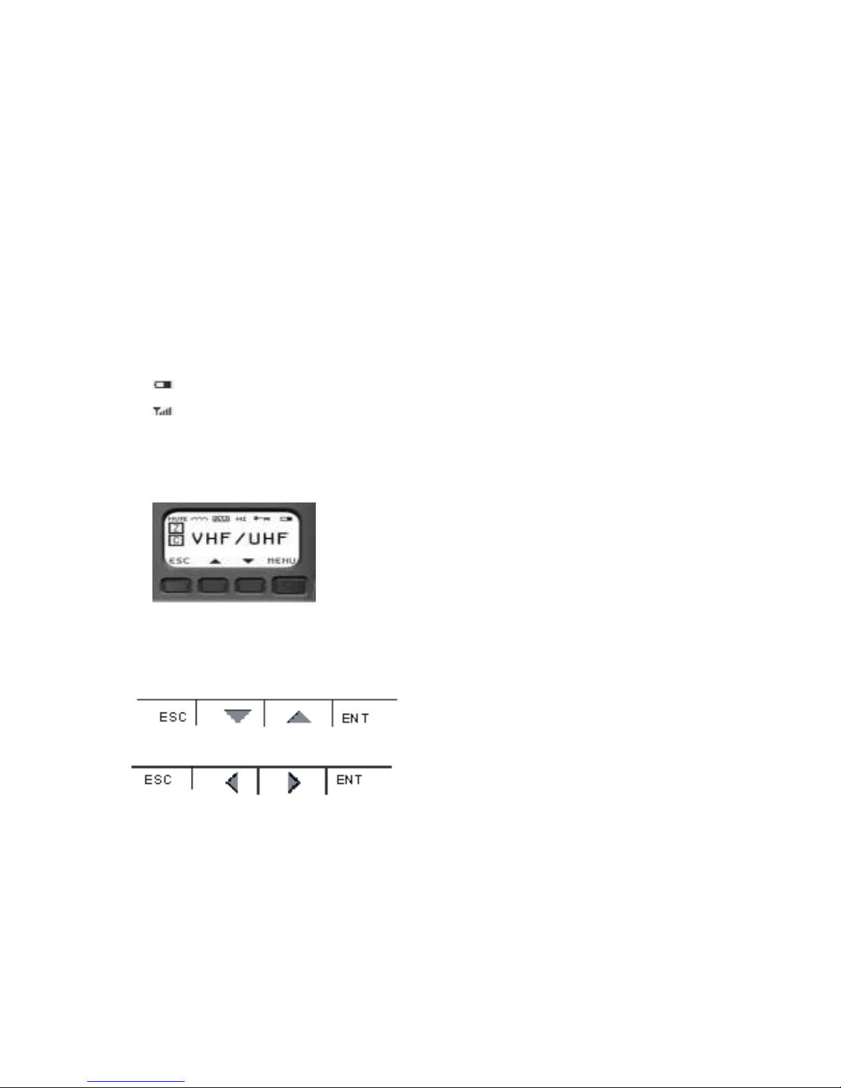
Display
On power up, the radio momentarily displays the Guardian II name and software version. The
display then indicates the operation status for the selected channel. Turn the channel knob to
select a different channel.
Group Type
Channel Type
The display consists of various icons as shown in the figure above.
Channel type icons: Group type icons:
C
= channel B = bank
S
= shadow channel Z = zone
H
= home channel a around a zone type means it
s is included in the zone scan list
E
= emergency
P
= priority channel
Page 10
a around a channel type
means it is included in a scan list
Modulation type icons:
AW
= analog wideband
AN
= analog narrowband
DG
= digital
around the modulation type means some form of selective squelch is active for the channel
a
(NAS, CTCSS or DCS)
Other icons:
TX
= transmit channel in scan mode
RX
= receive channel in scan mode
TA
= talkaround
∩∩∩
= repeater
= encrypted
U
= unit ID call mode
= Battery Gauge
= Signal Strength Indicator
Navigation Buttons
These four buttons perform actions determined by what appears on the display.
The
MENU
button lets you access the internal software menus, toggle between a setting and its
value and save data. The
ESCAPE (<ESC>
) button allows you to return to a previous display
without making changes to values. The Scroll up and down buttons highlight menu choices for
selection.
The left and right scroll buttons highlight alpha and numeric characters when changing values.
Keypad
Because all channel information and switch definitions can be programmed by the PC
Programmer, the keypad is not required for basic operation of the radio. The keypad is used to
select options within the radio, or to reprogram almost any setting. It is used for DTMF signaling,
keypad programming and feature selection, among other things.
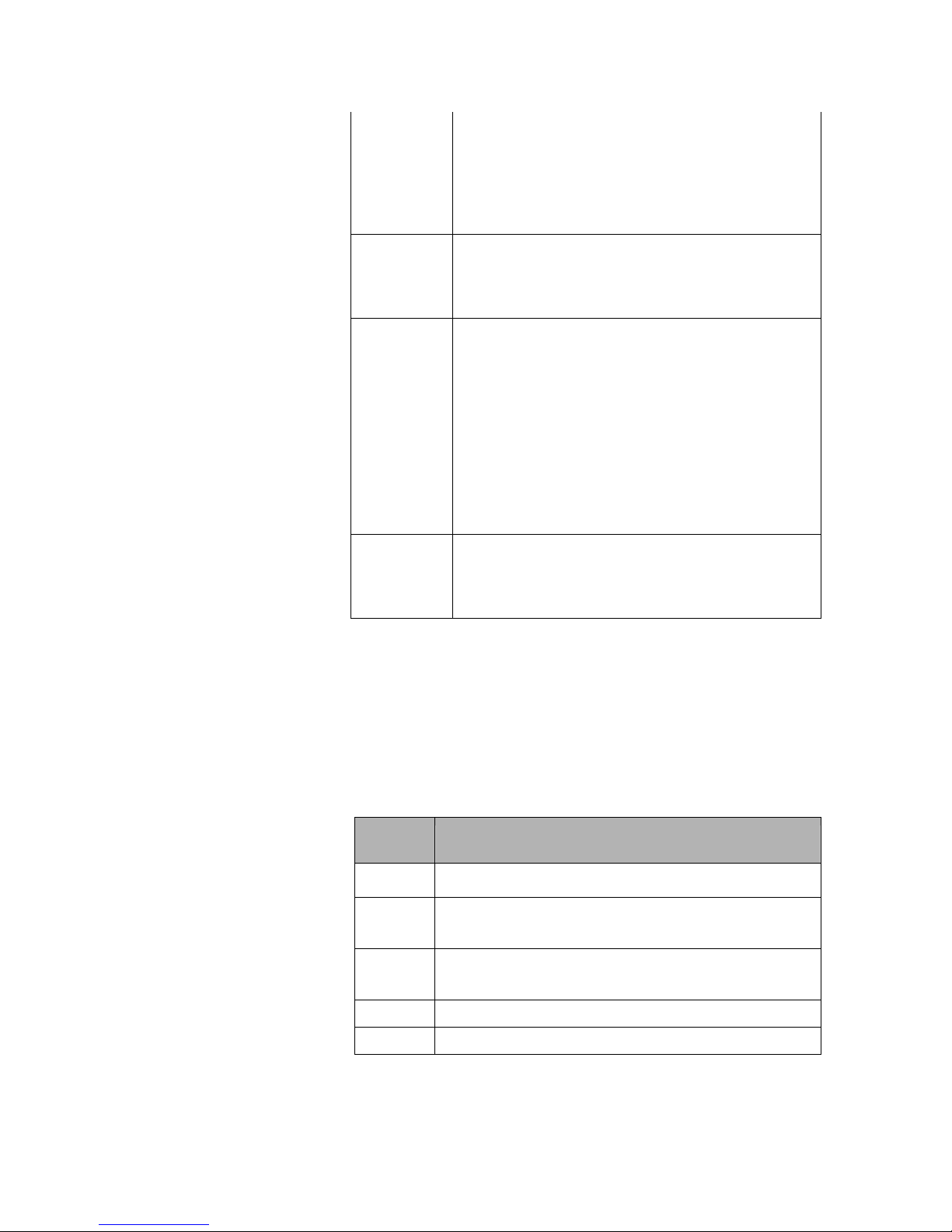
Collar Switch (three position)
The 3-position (A, B, C) collar switch located under the ON/OFF Volume control is programmed
using the PC Programmer. Ask your radio programmer how it is setup to function.
Page 11

Function Description
Scan
Sets scan mode to On, Priority, or Off.
Position A: Scan, Priority scan, or off
Position B: Scan, Priority scan, or off
Position C: All scan modes off
Monitor
(includes
squelch
adjust)
Provides monitor and carrier squelch adjust functions.
Position A: Squelch adjust mode (carrier squelch only)
Position B: Monitor on
Position C: Programmed squelch mode (monitor off)
Zone
Select
Selects Zone A, B or C.
Position A: First zone assigned in current bank
Position B: Second zone assigned in current bank
Position C: Third zone assigned in current bank
Talkaround Toggles channels between talkaround and repeater
modes.
Position A: Talkaround enabled
Position B: Talkaround disabled (repeater mode)
Position C: Talkaround disabled (repeater mode)
Hi/Lo
Power
Toggles the power setting from high to low. This
setting is programmed into each individual channel
and can be the same power level.
Position A: RF Power HI
Position B: RF Power LO
Position C: RF Power LO
The radio reads the toggle switch on power-up and
periodically. Setting is retained if battery is removed.
Collar Switch
The 2-position (o, ø) collar switch located under the channel selector and is programmed using
the PC Programmer. The most useful function of this control is to enable/disable encryption of
the selected channel.
Encryption Enables or disables encryption. The toggle positions:
Position A: TX encryption enabled
Position B: TX encryption disabled
Disabled
Position C: TX encryption disabled
Ignores any attempted use and provides an error tone.
Page 12

Auxiliary Buttons
These Six programmable buttons are located on the side panel and the front (under the display) of
the radio and their use depends on how they are programmed using the PC Programmer. Ask
your radio programmer how they are set up to function.
The three most commonly used functions of these buttons are
Hi/Lo Power (useful for conserving battery life), Monitor (valuable when using analog FM
channels - also includes squelch control)
, and Next Zone.
Function Description
Hi/Lo
Power
Monitor
(includes
squelch
adjust)
Next Zone
Scan
Priority
Scan
Toggles the radio power setting from Hi to Lo. These
settings are programmed into each channel.
Provides monitor and carrier squelch adjust
functions.
Momentary press: Momentarily opens squelch.
Press and hold for 2 seconds: Locks radio into
squelch open condition. To return to normal mode,
momentarily press the monitor button.
Press and hold for 4 seconds: Activates carrier
squelch adjust (on carrier squelch adjust channels
only). To return to normal mode, momentarily press
the monitor button.
Cycles the radio through all zones of the current
bank. The zone is stored and retained as long as the
battery is on the radio. If this is pressed and held
until an audible tone is heard the direction of Next
Zone is reversed.
Toggles the scan mode on and off.
Toggles the priority scan mode off and on. This does
not affect regular scan, which works independently.
Scan List
Add and
Delete
Backlight
Disabled
Toggles the channel’s scan list off and on. Affects
the current channel only.
Toggles the radio’s backlight from off to Bright to
Dim with each key press. The backlight timer is not
affected. (The Bright+RX and Dim+RX turns the
backlight on when a signal is received)
Ignores any attempted use and provides error tone.
Page 13
Encryption Toggles TX encryption from off to on for channels
programmed with encryption enabled. RX
encryption is unaffected. Encrypted channels can be
set by the PC Programmer to ignore this switch. The
switch has no effect on these channels (they stay
encrypted).
Home
Channel
Toggles the active channel from the Home Channel
to the currently selected channel. Normal operation
resumes on channel, zone, or bank change. This
setting can be changed using the keypad.
Keypad
Disable
To activate the key, press and hold it for 1 second.
Continue pressing to disabled the keys you want.
1st press: All keys enabled (front and side).
2nd press: Keypad disabled (side keys and toggle
switch still enabled).
3rd press: Keypad, side keys and toggle switch
disabled (PTT remains enabled).
This function can also be accessed from the keypad
<ESC>
by pressing and holding
<ENT>
holding
again.
. To regain access, do these steps
then pressing and
Talkaround To bypass a repeater and talk directly (DIRECT,
CAR-CAR, TAC, etc.) on a repeater channel.
Toggles channel from talkaround mode to repeater
mode.
Push-to-Talk (PTT)
The Guardian II radio is normally in a ready-to-receive mode (PTT not depressed). To transmit,
press PTT and speak into the radio in a normal voice. Distance from the radio is not critical, but
2-6 inches from the radio is optimal. To return to receive mode, release PTT.
Status Indicator
The LED indicates several conditions of the radio.
Indicator Description
Red
Steady
Green
Flashing
Green
Radio is transmitting.
Radio has detected RF traffic on the channel.
Radio has detected an encrypted signal on the channel.
Page 14

Internal Speaker and Microphone
The internal speaker is active when external audio accessories are not used. The internal
microphone is active when you press the PTT button.
Emergency Button
The red emergency button on top of the radio is typically used for P25 Emergency operation but
can be programmed by the PC Programmer for any of the following functions. Ask your radio
programmer how it is set up to function.
Function Description
Disabled
Emergency
Mode
Zeroize
Ignores any attempted use and provides an error
tone.
The emergency channel is programmed by the PC
Programmer or from the radio keypad. If left unused,
the current channel serves as the emergency channel.
In P25 mode the emergency bit is set. Since analog
modes have no similar function, the radio performs
an open-mic function for the duration and interval
programmed by the PC Programmer.
Erases all encryption keys in the radio.
Alert Tones
Audible tones provide important information about the radio’s operating state or condition.
Tone
Pitch
Low
Low
Tone Length Description
Burst
Error pressing button, failed self-test,
talk time out warning or empty
Steady
channel.
Talk time out, talk inhibit, invalid
mode or radio locked.
Backlight
The backlight is illuminated when a signal is received (if programmed by the PC Programmer). It
is activated from an auxiliary button (toggles through settings) on the radio or from the keypad
There is a slight reduction in battery life if using the backlight, but not significant. The power
drain difference between dim and bright is negligible.
Medium
Medium
High
High
Burst
Pulsed
Burst
Pulsed
Button press, passed self-test or
receiving in clear voice.
Emergency call mode or key error.
Low battery.
Individual call.
Page 15

3: OPERATING THE RADIO
The Guardian II operates with most of its features already programmed into the radio. Request a
list of the functions that are assigned to the buttons and switch on your radio.
Quick Start
Before proceeding, the radio must be set up using the Guardian PC Programmer. If necessary,
refer to Chapter 2, Controls and Indicators.
1. Battery
2. Antenna
3. Power-up
4. Select
channel
5. Receive
6. Transmit
Install a charged battery.
Install the correct antenna for the frequency
being used. Do not operate the radio without
an antenna.
Turn the power-volume knob clockwise about
halfway around. Set the volume to a
comfortable level when a transmission is
heard. A 5-10 second delay at power-up is
normal.
Turn the channel knob until the desired
channel is shown on the display.
Listen using the built-in speaker. Note: the first
volume knob click position mutes the speaker.
Press
microphone. Release
speaking. Do not press
necessary after talking.
PTT
and speak about 4 inches from
PTT
when finished
PTT
longer than
Selecting Channels
Use the rotary channel selector to select the desired operating channel. Changing Zones also
makes other preprogrammed channels available for use. (See Zone Select)
Selecting Shadow Channels
The Guardian II can be programmed to detect any type of analog FM signals and any
combination of P25 digital signals, up to 9 sets of analog/digital settings. This is done with the
use of shadow channels. Once received, the radio is programmable to transmit either in kind or
strapped to its channel selector.
This mix-mode of operation enables digital systems to seamlessly integrate into older analog
systems. The preferred signaling mode can be set up for a P25 digital signal, be able to receive
any analog signal and respond back to the operator on the analog radio.
Applications
Some applications that are available using shadow channels are:
Page 16

•
Simultaneous analog and digital operation
•
CTCSS (or DCS) picklists used to choose repeaters
•
P25 NAC picklists used to choose repeaters
•
Multiple encryption use
•
Supervisory talkgroups
Accessing Shadow Channels
Shadow channels must be programmed into the radio to access them. For information on
Note:
programming shadow channels,
refer to “Adding a Shadow Channel” on page 5-15).
From the keypad, select shadow channels by pressing * then the appropriate shadow channel
number (for example, pressing *3 selects shadow channel 3). Return to the primary channel by
<ESC>
pressing **, *0, or
.
A talkback timer allows you to transmit within 10 seconds on the shadow channel. The timer is
reset at the end of each received message. When a transmission is received on a shadow channel,
an
S
displays as the channel type.
Selecting Home Channel
If a button is programmed with a home channel, press the assigned home button. The home
channel status displays. To assign a different home channel, access the main menu
“Home Channel” )
(refer to
Selecting a Zone
If one of the auxiliary buttons is programmed for Next Zone, press that button to toggle through
the zones. If the 3 position collar switch is programmed for Zone Select, rotate the switch to
select the desired zones. A zone is also selectable by accessing the main menu
Menu”)
.
(refer to “Select
Selecting a Bank
If one of the auxiliary buttons is programmed for Next Bank , press that button to toggle through
the Banks. Banks are selected by accessing the main menu
(refer to “Select Menu”)
.
Selecting Talkaround
Talkaround forces the transmit frequency to an equal receive frequency for a selected channel.
This is useful for direct radio-to-radio communication when a repeater is unavailable. If a button
or switch is programmed for talkaround, press the assigned button or position the toggle switch
appropriately. Talkaround is turned off and on by accessing the main menu
Menu”)
.
(refer to “Select
Adjusting Analog Carrier Squelch
If an auxiliary button is programmed to access the squelch adjust (Monitor), press the button for
at least 4 seconds until the squelch adjust status displays. Use the scroll buttons to change the
ESC>
squelch setting. Press <
Squelch is also adjustable from the main menu
to save the value and return to normal operation.
(refer to “Channel Submenu”)
.
Page 17

Transmitting
Press the
button when finished speaking. Do not hold the
programmed for receive-only sound an alert tone, display
Your radio may be setup with the Transmit Inhibit feature. This feature locks the PTT switch to
keep users from talking over other radio conversations. It can also be setup to allow you to
transmit over the signal anyway if the PTT switch is pressed twice within approximately ½
second. The transmit inhibit settings are accessed from the main menu
Submenu”)
Your radio may be set up with the Transmit Timeout feature that shuts the transmitter down after
a pre-determined time. This is useful for preventing long transmissions when PTT is accidentally
pressed. Transmit timeout defaults to off, but can be programmed from 0 minutes (off) to 5
minutes, in 30 second increments (
PTT
button and speak normally about four inches from the microphone. Release the
PTT
longer than necessary after talking. Channels
RX ONLY
, and do not transmit.
(refer to “Global
.
refer to “Global Submenu”).
Scanning
Scanning is available on the Guardian portable at a rate of about
8 channels per second. Various types of scanning exist. The radio can be programmed to talkback
on the received channel or on the currently selected channel.
Guidelines
To maximize the efficiency of scanning channels, use the following guidelines:
•
Keep the number of channels in a scanlist to the minimum required. Since the radio scans
at about 8 per second, each channel is scanned faster if there are fewer channels to scan.
•
If scanning channels with noise squelch settings, higher carrier squelch values provide
faster results (improvements above values of 8 are minimal), but higher squelch values
reduce effective range.
•
If scanning multiple channels with the same frequency (regardless of squelch values), use
shadow channels when possible. A primary channel with all its shadows still scans at the
rate of about 8 per second.
PTT
Setup
1.
2.
3.
Create a scan list. Display the channel to include in the scan list. Use the scan list add/delete
C
button to toggle channels on/off the scan list. A square around the
indicates the channel is
in the scan list. To remove the channel from the scan list, press the left scroll button. The
C
square around the
is cleared.
To add a zone to the zone scan list, set the radio to the zone to include in the scan list. Press
and hold the scan list add/delete button to toggle the selected Zone on/off the Zone Scan List.
A square around the
Z
indicates the zone is in the scan list.
Select a scan mode. The mode is preprogrammed into the radio but you can verify or change
it using the keypad.
Refer to “Scan Menu”.
The modes are normal scan, scan zones in the scan
zone list or scan all frequencies programmed into the radio.
Activate scan. Use one of the following methods:
•
Use the preprogrammed auxiliary button
•
Use the preprogrammed collar switch, or
•
Access the main menu
(refer to “Scan Menu”)
The selected mode of scanning is evident by the display. Examples are:
SCAN****
Page 18

ZONE****
SRCH****
Priority Scanning
Priority scanning is independent of regular scanning and allows you to sample a priority channel
at various rates while listening to another conversation. It is not necessary to be scanning to
monitor a priority channel. Up to 2 priority channels can be selected.
Priority scan breaks into actively received signals at a priority interval rate setup in the PC
Programmer or through the programming menu.
Priority scanning is set up by creating a priority scanlist, selecting a priority mode and activating
priority scan.
1.
Create priority channels. While you can have up to two priority channels, one is
recommended. This is programmed into the radio but can be changed by accessing the main
menu. To select priority channels from the menu,
2.
Select the priority scan mode. This is programmed into the radio from the PC Programmer. It
refer to “Scan Submenu”).
is highly recommended to leave this at its default value (PR1), unless it is absolutely
necessary to scan two priority channels. To change this mode using the keypad,
Menu”).
3.
Activate priority scan. Several options exist for turning priority scan on or off.
•
•
•
Use the preprogrammed auxiliary button
Use the preprogrammed collar switch
Use the keypad (
refer to “Scan Menu”).
You know you are scanning when the top row of the display briefly flashes one of the
following:
refer to “Scan
scanP1**
scanP1P2
Page 19

4: OTHER STANDARD FEATURES
Cloning Radio to Radio
Note:
The cloning described in this section is for standard radios. If you have a radio equipped
with the Fire Features option, refer to Chapter 8.
Radio to radio cloning enables the transfer of channel settings from one radio into another radio.
Information that is cloned:
•
All channel settings
•
Channel assignment to zones
•
Zone assignments to banks
•
Special function channels and assignments
Information that is not cloned:
•
Encryption keys
•
Passwords
•
P25 Unit ID
•
Auxiliary button functions
•
Toggle switch functions
•
Emergency switch functions
•
Other global parameters
Note:
Do not turn radios off or disconnect cable during cloning process.
To clone one Guardian II portable radio to another:
1.
Turn off both radios.
2.
Connect One end of the Source End of the clone cable to the source radio. (the radio with the
information to be cloned).
3.
Connect the other end of the cloning cable to the side connector of the target radio
Note:
Guide the top and bottom pegs on the end of the cable into the corresponding slots on
the radio’s side connector. When they click together, use your thumb to hold the cable to the
radio and turn the screw handle until the cable is tight against the radio.
5.
Turn on the target radio and the source radio. The source radio indicates the cloning
mode.
6.
Press PTT on the source radio. Banks 1 to 4, with all of their zones and channels, are sent to
the target radio. The source radio can then be used to clone another radio.
DTMF Dialing
DTMF dialing transmits (including sidetone) the DTMF tone that corresponds to a pressed key. It
is used primarily for:
Page 20

•
Entering a repeater code for access to a repeater.
•
Accessing a repeater with a phone patch to dial a phone number.
•
Accessing remote weather stations using DTMF tones A, B, C, and D by pressing the
corresponding navigation keys.
To access while in any analog mode, press the PTT button and the desired key.
Page 21

Emergency Mode
To activate Emergency mode, press and hold the Emergency button (must be programmed as
Emergency) for about ½ second. The emergency mode remains active indefinitely until
deactivated. To deactivate, press and hold the button again, or turn the radio off and on.
Emergency channels are setup using the keypad (
EMG)
setting (
is left empty, the current channel serves as the emergency channel. In P25 mode,
refer to “Global Submenu”).
If the Emergency
the emergency bit is set. Since analog modes have no similar function, the radio performs an
open-mic function for the duration and interval programmed by the PC Programmer.
Two types of operation are available for the emergency mode: Normal and Silent. The operation
is selected from the PC Programmer or the keypad (
refer to “Global Submenu”).
In Normal
Emergency mode, each time the radio transmits or receives emergency signals, the LED flashes
orange, an audible alarm is sounded, and the display indicates
mode,
EMERGENCY
still displays but the flashing lights and sounds are disabled.
EMERGENCY
. In Silent Emergency
Transmitting P25 Individual Calls
P25 radios include a feature that allows an individual radio to be targeted to transmit to. This is
accomplished by the unique UnitID that all radios can be programmed with, and transmitted in
the P25 CAI waveform. This UnitID can have a value of 1 to 9,999,999 (decimal).
Note:
If secure communications is desired, use encryption keys. Do not rely on P25 Individual
Call alone.
To initiate a P25 Individual Call:
1.
Select the desired P25 digital channel.
2.
Press the Soft Key assigned to Individual Call or access the main menu and choose
3.
Scroll down to
4.
Toggle
5.
Scroll to
6.
Press
7.
Press PTT.
When a P25 Individual Call is received, the radio generates a special tone indicating that an
individual call is being received.
IDCL
<ESC>
IDCL
and press
to ON and press <
DEST
and press
<ENT>
.
ENT
>.
<ENT>
. Enter the destination UnitID (1 to 9999999).
twice to display the Individual Call screen.
SELECT
.
If the receiving radio responds within 10 seconds, it remains in Individual Call mode. If not it
returns to normal operation.
8.
To exit to normal operation prior to the 10 second timeout, press <
mode is exited, and the normal operating screen displayed.
ESC
>. The individual call
Page 22

5: RADIO SETTINGS AND PROGRAMMING
Changing the radio’s functions and features are permitted or restricted according to agency policy
and federal law. Internal radio software provides limited access to certain features and settings.
Information in this manual may or may not pertain to your radio. Consult the programmer for the
features and functions that are enabled for you.
Menu Structure
To access the main menu:
1.
With the radio on, press the
section on page 2-3
.
Use the scroll buttons to highlight a menu selection.
2.
3.
Press
<
ENT
>
to access its submenu. Press
Submenus can consist of more than one page and are cyclic (roll over to the first page after
the last page). When a submenu continues on more than one page, a
right corner. Continue scrolling down through the selections.
The Guardian operates with most of its features already programmed. The ability to change
certain programmed settings is made available by accessing
E
NTER
(<
ENT
>)
button. If necessary,
E
SCAPE
(
see the “Navigation Buttons”
<
ESC
>
) to return to the previous display.
appears in the lower
menus.
Required Passwords
Passwords may be required to operate the radio and to access the Program (
ALERT
(
), and encryption (
KMGR
) menus.
1.
Use the keypad to enter your predetermined password.
2.
If
INVALID ENTRY
invalid password is attempted 3 times consecutively,
displays, the entered password is incorrect. Press
ACCESS DENIED
PROGRM
<
ESC
>
and try again. If an
is displayed.
)
, Alert
Page 23

3.
Press
<
ESC
>
to resume radio operation.
4.
To enter a new valid password, power the radio off and on.
When menus are disabled, the radio displays
MENU DISABLE
. Consult authorized personnel for
guidance.
Entering Data
Enter alphanumeric and numeric data using the keypad. Each Key has a number and
alphanumeric letters associated with it. For Example when entering data and pressing the 2 key
the display will show the following: A,B,C,2,a,b,c.
.
Scan Menu
The scan menu allows you to enable and disable the normal scanning and priority scanning and
to select the type or mode of scanning to use.
1.
Access the main menu.
Scroll to highlight ROPTNS and press ENT.
Scroll to highlight
2.
SCAN
, and press
By pressing the down scroll arrow.
<
ENT
>
.
Page 24

3.
Choose from the following settings.
Setting Description
SCAN
Turns normal scanning on or off.
PRSCAN
SCMODE
Turns priority scanning on or off. Scroll to
PRMODE
to select the priority scan mode.
Select one of three scan modes.
S
CAN
: scan currently selected channel and all
channels within the current zone designated as
scan channels.
Z
ONE
: scan all zones in the zone scanlist.
S
EARCH
: scan all channels programmed into the
radio regardless of their scan list assignments. If
any channels exist with a squelch value of none,
or signals that are always present, the radio stops.
Press
<ESC>
to terminate the reception and
PR1+2
.
3.
continues the scan.
PRMODE
Select
PR1
or
The table below shows an example of how channels and zones might be set up for a radio and
how they would be received with each mode. It shows the radio is on Zone 1, Channel 1. Scan
list channels are indicated by an X and Zone 3 is the only zone in the scanlist (SL).
•
If
SCAN
is chosen, scanning detects Zone 1, channels 1, 4, and 7.
•
If
ZONE
is chosen, scanning detects Zone 1, channels 1, 4, 7 and Zone 3, channels 4, 8, 12.
•
If
SEARCH
is chosen, scanning detects all channels.
ZONE
1
2
3 (SL)
Chan 1 Current X
Chan 2
Chan 3 X
Chan 4 X X
Chan 5 X
Chan 6
Chan 7 X
Chan 8 X
Chan 9 X
Chan 10
Chan 11 X
Page 25

Chan 12 X
Chan 13
Chan 14
Chan 15 X
Chan 16
Page 26

Select Menu
The select menu allows you to designate a different zone or bank to a button or switch on the
radio. You can also select an individual call and enable or disable Talkaround.
1.
Access the main menu.
Highlight ROPTNS and press RNT.
Scroll to highlight
2.
SELECT
and press <
ENT
>.
3.
Choose from the following settings:
Setting Description
ZONE
Select an alternate zone. If an auxiliary button is
programmed as Next Zone
the current zone until another is selected. If the switch
is set to Next Select, and a Zone is selected via the
keypad, that zone is permanently in the switch setting.
BANK
Select an alternate bank. Having 4 banks allows you
to have 4 different radios in one (subject to the
maximum number of 1024 channels). Reverts to the
default bank if the battery is removed for an extended
time.
IDCL
For placing a Unit ID call. Standard radio only.
and is pressed, it replaces
TKGP
TKRD
Talkgroup. Future development.
Talkaround is for direct radio-to-radio communication
when a repeater is unavailable. Forces a transmit
frequency to a receive frequency for a selected
Page 27

3.
channel. Select off or on.
Home Channel
The Home channel allows you to quickly access a commonly used channel. An auxiliary button
can be programmed for home channel use.
1.
Access the main menu, highlight ROPTNS and Press ENT.
2.
Scroll to highlight
3.
To assign a different home channel,
HOME
and press
<
ENT
>
.
Global Submenu
.
Program Menu
The program menu allows you to change global radio settings, channel settings, scan settings,
and passwords.
1.
Access the main menu, highlight ROPTNS and press ENT.
If a password is require enter the following screen will display.
2.
3.
If required, enter the password for this radio and press
<ENT>
.
Page 28

Global Submenu
1.
Select
ROPTNS
,
PROGRM, GLOBAL
and press
<
ENT
Pressing the down scroll key will go to through the following pages:
>
.
2.
Choose from the following settings:
Setting Value Description
LITE
(Backlight)
LT DLY
(Backlight
delay)
LTONRX
Bright, dim or off Enables, disables, and varies the
1 to 9 seconds
intensity of the LCD’s backlight.
Sets the time delay for the LCD and
keypad backlighting.
On or off
Backlight goes on when signal
received.
Page 29

TOT
(Time out
timer)
DISPLY
(Display)
30 to 300 seconds
in
30 second intervals
or off
Limits the duration of messages (30 to
300 seconds in 30-second increments).
Off setting allows unlimited
transmitting time.
Alpha or numeric Sets the display to either alpha or
numeric characters.
UNIT ID
HOM
(Home
channel)
EMG
(Emergency)
ALERT
TX INH
(Transmit
inhibit)
On or off
Home channel
designation
The ID of the transmitting radio.
Sets the home channel. The channel's
receive and transmit frequency is
displayed but cannot be changed.
Select the desired home channel using
Emergency
channel
designation
the channel knob. Press
confirm the new home channel.
Sets the emergency channel within the
active zone and bank. The channel's
transmit frequency displays but cannot
<ENT>
to
be changed. Select the desired
emergency channel using the channel
knob (if left empty, current channel
<
ENT
>
to confirm the
or
SILENT
and
EMG
displays. The
. In
NORMAL
Normal or silent
serves). Press
new emergency channel.
Sets the emergency call alert mode.
Choose
mode,
NORMAL
EMERG TX
radio beeps every time it transmits the
emergency message until deactivated.
In silent mode, there is no beep or
display.
Locks the PTT switch to prevent talking over other radio
conversations.
NAC
Inhibit transmission on a busy channel
using a different NAC.
NAC+O
CARR
CARR+O
TONE
TONE+O
NONE
Override NAC inhibit with two rapid
PTT presses.
Inhibit transmission on a busy channel.
Override CARR inhibit with two rapid
PTT presses.
Inhibit transmission on a busy channel
using a different squelch tone.
Override TONE inhibit with two rapid
PTT presses.
No transmit inhibit.
Page 30

BAUD
4800, 9600, 19200, 38400 BAUD Rate
2.
CNTRLS
Enable/Disables
Turn radio controls on or off.
Channel Submenu
This submenu allows you to add new channels or make changes to existing channel settings.
Channels can be selectively locked, preventing you from making changes. If you select a locked
channel,
Adding a New Channel
CHANNEL LOCKED/ACCESS DENIED
is displayed.
The following is an example of programming a new channel into an empty slot. This same
process is used to modify existing channels.
Note:
The new channel is assigned to whatever channel position the radio was selected to at the
time of initial programming.
1.
From the main Menu go to ROPTNS, PROGRM, CHANNEL and press enter. You may be
required to enter a valid password to proceed.
2.
Press
<
ENT
>
.
4.
Press
<
ENT
>
again to access the tag setting for entering a name for this channel. Use cell
phone techniques to enter the name. For example, to enter N, press the 6 key twice. To enter
<
ENT
>
E, press the 3 key twice. To enter W, press the 9 key once. Press
to finish.
5.
Scroll down to the
MODE
setting, press <
ENT
> and change the mode to
ANALOG
.
Page 31

6.
Scroll down to RX, and set it to 154.600000 MHz.
7.
Scroll down to the next screen. Leave
RXSQMD
at
CTCSS
.
8.
8.
Scroll down and to Tone and Press ENT. Use the up arrow until the desired to is found.
8.
Scroll to TX and set it to 154.6000000 MHz.
9.
Scroll to
TXMSQMD
and set it to
CTCSS
.
Set
TON
to
67.0 XZ
.
Page 32

10.
Scroll down to the RF Power screen and set
11.
Scroll down to the next screen. Press
LO PWR
<
ENT
>
to accept the channel
to
0.5W
and
HI PWR
to
.5W
.
12.
settings.
Press
<
ESC
>
several times to get back to the operating screen. The new channel is ready to use.
To simplify programming, assume the following defaults unless told otherwise by the person
assigning channel settings:
•
RX Frequency must always be specified
•
TX Frequency must always be specified (unless RX Only)
•
TAG is any 8 character alphanumeric value
•
ID is internal radio information and cannot be changed
•
If using a repeater, a Transmit CTCSS, DCS, or NAC code must be assigned.
Refer to the following tables that describe the different settings for analog and digital channels,
respectively.
Analog Settings
Setting Value Description
ID
TAG
User ID
Name
Software assigned identifier.
User defined channel name.
Page 33

MODE
B/W
Analog
12.5 KHz or
25 KHz (default)
Analog settings displayed.
Bandwidth.
RX
RXSQMD
TX
TXSQMD
136 MHz to
174 MHz
NONE
NOISE (default)
SQ=
DCS
CODE=
CTCSS
TON
136 MHz to
174 MHz
None
Receive frequency.
No receive squelch.
If you choose noise, adjust the
squelch level by highlighting
and scrolling left and right.
If you choose DCS, highlight
CODE
and enter the DCS code.
If you choose CTCSS, highlight
TON
and enter a CTCSS tone.
Transmit frequency.
No transmit squelch.
SQ
LO PWR
HI PWR
CTCSS
TON
DCS
CODE=
0.5, 0.1, 1.0,
2.0 (default), 5.0
0.5, 0.1, 1.0, 2.0,
5.0 (default)
If you choose CTCSS, highlight
TON
and enter a CTCSS tone.
If you choose DCS, highlight
CODE
and enter the DCS code.
Low transmit power setting.
High transmit power setting.
Page 34

Digital Settings
Setting Value Description
ID
TAG
MODE
User ID
Name
Digital
Software assigned identifier.
User defined channel name.
Digital settings displayed.
ENCRPT
RX
ENABLD
136 MHz to
174 MHz
Select from the available
encryption keys.
Change the receive frequency if
necessary.
RXNAC
RXSQMD
ENCRPT
TX
TXNAC
TXSQMD
TALKGP
NAC value
Enter the receive network access
code. 293 is default.
P25NOR
P25SEL
TALKGRP=
P25 normal squelch mode.
P25 selective squelch. If you
choose this, highlight
enter the hexidecimal talk group
P25MON
ENABLD
identifier.
P25 monitor squelch mode.
Select from the available
encryption keys.
DISABD
136 MHz to
174 MHz
NAC value.
P25SEL
Talkgroup identifier Enter the talkgroup identifier.
Encryption is disabled.
Change the transmit frequency if
necessary.
Enter the transmit network access
code.
Unchangeable.
TALKGRP
to
LO PWR
HI PWR
0.5, 0.1, 1.0,
2.0 (default), 5.0
0.5, 0.1, 1.0, 2.0,
5.0 (default)
Low transmit power setting.
High transmit power setting.
Page 35

Adding a Shadow Channel
To add a shadow channel to a primary channel, perform the steps in the following sequence:
1.
Determine the next available shadow channel (press *1, *2, etc. until an error tone is heard
indicating the channel is empty).
2.
Select
PROGRM, CHANEL
3.
Press *x to get to the desired new shadow channel.
4.
Scroll through the settings and change as necessary. Settings that can be changed are:
•
Channel type: analog or digital
•
Bandwidth
•
Key assignment
•
Squelch (CTCSS, DCS, P25 NAC, P25 Talkgroup)
while on the desired primary channel.
All other settings must remain unchanged.
Shadow channels can be programmed to transmit back on the mode just received or the mode
selected by the channel selector knob. This is valid only for the Shadow Channel delay period.
The delay period can be overridden which would allow transmissions on the primary channel at
any time by pressing
. This is programmed from the Scan Submenu,
Scan Submenu
<ESC>
Lists Submenu
Note:
The Lists submenu is only available with the Fire Features option.
This submenu allows you to add or delete a Unit ID to or from the call list.
.
1.
Press <
2.
Scroll to
3.
Scroll to
4.
Press <
•
•
5.
To exit the P25 UnitID mode, press <
ENT
> to access the Main Menu.
PROGRM
LISTS
ENT
To add a new ID, select
and press <
and press <
ENT
ENT
>.
>.
IDCL
> and do one of the following:
ADD NEW.
Enter the unit ID name and press <
To delete an existing ID#, select
Verify the deletion: Select
DELETE.
YES
and it’s deleted. Select NO and the list is displayed again.
is highlighted.
Enter the Unit ID number (1 to 99) and press <
ENT
> to add it to the list.
Scroll to the name to delete and press <
ESC>
.
Scan Submenu
This submenu sets the basic functions of scan delay, revert mode, and priority-scan channels.
1.
Press
<
ENT
>
to get to Main Menu screen.
2.
Select
ROPTNS, PROGRM
3.
Change the settings as necessary, using the table below as reference.
and then
Setting Description
DELAY
(Scan delay)
SCAN
.
Enter the number of seconds you want the
radio to stay on the channel after the last
transmission ends and before scanning
resumes.
ENT
ENT
>.
>.
Page 36

RVERT
(Revert channel)
LSTSEL
LASTRX
HOME
REPLY
The radio switches to the revert channel when
scan is disabled.
Last channel selected.
Last channel received.
Home channel.
Length of time in seconds to reply to a call.
3.
MONTR
P1
(Priority 1 channel)
P2
(Priority 2 channel)
(
Monitor)
Length of time in seconds the radio remains
on a channel picked up during a scan.
First priority channel. Select this and press
<ENT>
. Move the channel knob to the desired
<ENT>
P1 channel. Press
P1
switches to
this channel.
when activity is detected on
to save. The radio
Second priority channel. Move the channel
knob to the desired P1 channel. Press
P2
save. The radio switches to
detected on this channel.
when activity is
<ENT>
to
Page 37

Password Submenu
This submenu changes the current six-character password.
1.
From the
2.
Enter the old password using the keypad and press
INVALID ENTRY
Note:
3.
Turn the radio off and on again if necessary.
4.
When the old password is accepted, enter the new password.
5.
Confirm the new password by entering it again. If the new password is entered incorrectly,
CONFRM PSSWRD
6.
If the new password is accepted,
PROGRM
menu, scroll to
displays. Press
PASSWRD
<
ESC
>
and try again.
Three consecutive invalid entries and
is displayed.
CONFRM PASSWORD ACCEPTED
and press
OLD PASSWORD LOCKED
<
ENT
>
.
<
ENT
>
. If the entered password is incorrect,
is displayed.
is displayed.
COVERT Menu
This menu is for setting the radio to covert operation including muting the speaker and setting
alarms, beeps, and backlighting. Covert settings override all other radio settings.
1.
From the main menu scroll to ROPTNS
2.
Enter the predefined password for this radio and press
3.
Choose from the following settings.
Setting Value
, COVERT
and press
<
ENT
<
ENT
>
.
>
.
3.
BKLITE
(Backlight) Off/on, disable/enable backlighting
SPEAKR
KBEEPS
ALARMS
(User alert tones)
LED
(Status indicator)
SYSCALL
(Speaker)
Off/on, disable/enable speaker
(Key beeps) Off/on, disable/enable key beeps
Off/on, disable/enable user alert tones
Off/on, disable/enable LED status indicator
System call on or off
Page 38

Encryption Menu
This menu is for modifying the encryption settings setup in the PC Programmer.
1.
From the main menu, scroll to
2.
Use the keypad to enter the password for this radio.
3.
Press
<
ENT
>
.
4.
Choose from the following settings:
ROPTNS, ENCRYPT
Setting Value
and press
<
ENT
>
.
4.
KEYSEL
ZEROIZE
DF KEY
(Key select)
Choose the active key for the
channel
(Zeroize keys) Zeroize key for channel or all keys
(Default key)
Activates the channel's default key
Page 39

6: ENCRYPTION OPTION
This chapter assumes knowledge of the standard operations of the Guardian II portable radios
detailed in the preceding chapters of this manual.
Introduction
When operating in the digital mode the radio is capable of secure communications by means of
software-based encryption and is fully compatible with any radio using P25 digital encryption
standards AES or DES-OFB. When the radio is operating in the secure mode, the transmission of
all tone squelch signals is disabled. The radio displays a key icon indicating that encryption is
active. Encryption keys are assigned on a channel by channel basis via the PC Programmer or the
radio’s keypad.
The PC Programmer has an Encryption Lock option on a channel-by-channel basis that provides
the opportunity to ensure that selected channels always transmit an encrypted signal.
Encryption is not available when the radio is operating in the analog mode.
Programming/Activation
•
Assign Encryption keys to channels using the PC Programmer or the main menu (
“Encryption Menu”).
•
Use the preprogrammed auxiliary button (toggles encrypted channels on and off).
•
Use the preprogrammed two position collar switch (turns encryption on and off).
•
Use the KVL device (to add keys to radio).
refer to
Zeroizing Keys
The radio can be programmed to immediately zeroize all encryption keys by pressing and
holding the Emergency button for 1 second (if assigned). The radio can also zeroize all
encryption keys, or can selectively zeroize individual keys using the radio’s keypad from the
Zeroize (
ZEROIZE
) submenu of the Encryption (
KMGR
) menu.
Encryption Keyfill
The radio can store up to 32 encryption keys and retains them until they are zeroized. Keyfill is
accomplished through the radio’s side connector using the PC Programmer or a key variable
loader (KVL CX or DX) device. The PC Programming cable or DES encryption cable is used to
load keys.
To perform keyfill using a KVL device:
1.
Turn off the target radio.
2.
Connect the KVL to the target radio.
3.
Turn on the radio. The radio automatically detects the KVL and
check the connections, and repeat the steps.
4.
Scroll to highlight the desired key slot and press
5.
To verify the key identification, press ID for the key ID display.
6.
Press
TAG
to return to the key display.
7.
Press
<ENT>
to access the key transfer display.
<ENT>
to set the key slot selection.
KVL KEYFILL
displays. If not,
Page 40

8.
Press
PTT
on the KVL to initiate the key transfer. When the transfer is successful,
KEY DATA UPDATED
9.
Press
<ENT>
to return to the key tag or the key ID displays.
10.
Press
<ESC>
or turn the radio off and on to resume normal operation.
Note:
To stop the transfer at any time, press
displays. If unsuccessful,
<ESC>
FAILURE KEY DATA NOT UPDATED
.
For more information, consult the KVL instruction manual.
SUCCESS
displays.
Page 41

7: FIRE FEATURES OPTION
This chapter assumes a knowledge of the standard operation of the Guardian portable radio
detailed in the preceding chapters of this manual.
Introduction
The Fire Feature option is designed for users in a high-risk fire environment or a similar special
setting. This option adds the following features to the Guardian portable radio.
•
Tone picklist
•
P25 Talkgroup picklist
•
P25 UnitID picklist
•
Event bank for setting up an additional 3 zones of 16 channels each. Also known as
incident command (ICP) bank
•
Protected zone capability
•
Enhanced radio-to-radio cloning
Event Bank
A special Event bank simplifies incident command radio programming. It is the bank into which
single zones are cloned. The Event bank has some special characteristics:
•
The Event bank adds 3 additional zones of 16 channels each for an additional 48 possible
channels. This brings the total number of user channels up to 1120 (48 primary channels
plus 48 shadow channels). An additional four channels are reserved for the priority, home,
and emergency channels.
•
Unlike the main bank, each channel is independent. Changes to an Event bank channel do
not affect other channels of the same name in the radio.
•
Each Event bank channel can have a maximum of 1 shadow channel. If additional shadow
channels are cloned into the Event bank, only the first shadow channel is cloned (per
channel).
•
The Event bank is predefined as Bank 9.
•
Event zones are predefined as Zones 65, 66, and 67. Their zone names can be changed but
their zone ID remains constant. If the toggle switch is defined as Zone Select, the
following assignments apply:
Switch Position A: Zone 65
Switch Position B: Zone 66
Switch Position C: Zone 67
•
Zone 65, 66, 67 correspond to Zone A, B, and C respectively for the toggle switch and
used as Zone Select. Use the Next Zone auxiliary button to toggle through Zones 65, 66,
and 67.
•
Event Zones cannot be protected.
•
The Z icon on the display is inverted to provide a visual indication that the radio is in the
Event bank.
Cloning
The following cloning options exist for radio’s equipped with Fire Features. They can be
performed in any combination.
Page 42

•
Global only cloning
•
Legacy full channel, zone, bank cloning
•
Individual zone (up to 3 zones) cloning into the event bank
•
Tone (A/D TX squelch mode) picklist cloning
•
Talk Group picklist cloning
•
P25 UnitID picklist cloning
Cloning from non-Fire Features radios to/from Fire Features radios is fully compatible, but only
the standard full channel, zone, channel (no Event bank) option is possible.
Note:
Do not turn off or disconnect cable during the cloning process.
To clone one Fire Features equipped Guardian portable radio to another:
1.
Turn off both radios.
2.
Connect the red (cloning source) and black (PC) cables to each other.
3.
Connect the source end of the cloning cable to the side connector of the source radio (the
radio with the information to be cloned).
Note:
Guide the top and bottom pegs on the end of the cable into the corresponding slots on
the radio’s side connector. When they click together, use your thumb to hold the cable to the
radio and turn the screw handle until the cable is tight against the radio.
4.
Connect the target end of the cloning cable to the side connector of the target radio (the radio
to receive the information).
5.
Turn on the target radio and the source radio. The source radio indicates the cloning mode. (If
you see
CONNECT TARGET RADIO
, recheck your cable connection.)
These are the 6 cloning options from which to choose. A √ beside a cloning option indicates its
selection. Select as many as apply. To make a selection or remove a selection, scroll to that option and
press the corresponding √ button. When you’ve made your selection, press PTT to send the data. The
display indicates the progress of cloning:
ERASING SENDING COMPLETE
.
The options for cloning are described in the sections that follow
Note:
Zones can be protected using the PC Programmer. If a zone is protected, a password is
needed to clone over the zone or zones. If a source cloning radio and target cloning radio have
matching zone passwords, the password criteria is met. If a protected zone is cloned to another
radio (main or Event bank), the target radio’s zone does not become protected.
Page 43

Global Data
Check
GLOBAL DATA
to clone the auxiliary button settings, toggle switch settings, transmit
timeout settings, transmit inhibit settings, scan settings, and priority scan settings. The following
data is not cloned:
•
Keypad lock
•
Keypad disable
•
Scan Mode
•
Priority Scan Mode
•
Passwords
•
Unit ID and other Unit Identifiers
All Zones
Check
ALL ZONES
to clone all banks, all zones, and all channels. This includes data from the
Event bank.
Event Clone
Check
1.
EVENT CLONE
to clone a single zone or zones into the target radio’s Event bank
without affecting the remaining zones of the target radio. An interim screen is displayed
offering
SELECT ZONES
and
START CLONING
as options. Use Select Zones to choose a zone
(or zones) to clone into the Event Bank.
If Select Zones is selected, the following screen is displayed on both
radios.
Page 44

2.
On the source radio, scroll to the desired zone, and press
containing all zones in the current bank.
3.
Scroll to select the desired zone, and press
<ENT>
zones.
The target radio displays what is currently in its Event bank.
<ENT>
. A zone list is displayed
. Repeat this process for any remaining
When this process is complete, return to the previous screen and select
4.
START CLONING
When cloning is complete, the target radio automatically switches to the Event Bank.
The settings remain in place on the source radio to simplify cloning additional target radios.
Full EVBANK
Check this option to clone all zones, channels, and special channels (priority, home, emergency
channels) in the Event Bank. This data is first erased in the target radio.
TX SQL LIST
Check this option to clone the entire A/D transmit squelch (tone) picklist from the source radio to
the target radio. This includes the tag names and tones. Tones can be CTCSS, DCS, or None for
conventional analog channels, and NAC’s for P25 digital channels.
TALKGP LIST
Check this option to clone the entire Talkgroup list from the source radio to the target radio.
Talkgroups are applicable only for digital channels.
.
Page 45

Analog/Digital Tone Pick List
Tone pick lists are created in the PC Programmer. They are selected by accessing the main menu.
Up to 32 transmit tones (CTCSS, DCS) and 32 digital NAC codes can be programmed into the
radio. If one of these tones or codes is selected, the programmed tag name replaces the existing
channel name. The use of a tone picklist provides a permanent change to the channel.
To access these tones, the following options exist. For all of these, press the # key for a short
duration (press and release). A tone or code is replaced by the desired number:
•
Press # and single digit ID number.
•
Press # and 2-digit ID number.
•
Press # and 0 and single digit number.
•
Press # and single or 2 digits and <
•
A special case of pressing # 00 is reserved for removing the CTCSS or DCS tone on
analog channels.
Note:
If a channel is altered with the tone picklist that had a receive CTCSS or DCS tone
NO TXSQ
is displayed on the channel name.
ENT
>.
programmed to it, that channel is automatically set to receive carrier squelch.
Talk Group Picklist
The talk group list applies only to digital channels. It can only be programmed by the PC
Programmer or cloning. To access the list:
1.
Press and hold the * key until the talkgroup list is displayed. If no list exists,
displayed.
2.
Select the desired talkgroup, and press <
ENT
>. The talk group tag replaces the channel tag.
The use of a talk group list provides a permanent change to the channel.
EMPTY
is
Page 46

P25 Unit ID Call Picklist
If a call is received with a matching UnitID in the lookup table, the name is displayed. Otherwise,
the actual UnitID is displayed. It can be programmed by the PC Programmer or by accessing the
radio’s main menu. This picklist cannot be cloned.
To access an existing P25 UnitID picklist:
1.
Turn the channel knob to the desired P25 digital channel.
2.
Press and hold the # key to display the list. Do one of the following.
•
To make a UnitID call to someone who is not programmed into the radio, scroll to the first
selection,
•
To make a UnitID to someone in the existing list, scroll to one of the UnitID’s
ENTER #
programmed into the radio. Press <
channel name while in this mode. Press PTT.
3.
To return to normal operation, press
To edit the P25 UnitID picklist via the keypad:
1.
Press <
2.
Scroll to
3.
Scroll to
4.
Select
•
ENT
> to access the Main Menu.
PROGRM
LISTS
IDCL
and press <
To add a new ID, select
Enter the unit ID name and press <
•
To delete an existing ID#, select
Verify the deletion: Select
5. Press <
ESC>
to exit the P25 UnitID mode.
. Press
and press <
and press <
ENT
<ENT>
and enter the ID. Press
ENT
>. The name or UnitID number replaces the
<ESC>
.
ENT
>.
ENT
>.
>. Do one of the following:
ADD NEW.
YES
Enter the Unit ID number (1 to 999) and press <
ENT
> to add it to the list.
DELETE.
Scroll to the name to delete and press <
and it’s deleted. Select NO and the list is displayed again.
<ENT>
and PTT.
ENT
ENT
>.
>.
Page 47

8: TROUBLESHOOTING
The following table of symptoms, possible causes, and suggested corrective actions may be
helpful. Consult authorized personnel for further guidance.
Symptom Probable Cause Corrective Action
Radio does not
turn on
Cannot talk with
other users in
plain mode
Background noise
or other
conversations
heard
Error message on
display
Alarm message on
display
No power source
Radios programmed for
different frequencies,
squelch tones, talkgroup IDs
Other users on channel
or improper squelch
tone setting
Operational error in
radio
Encryption alarm in
radio
Supply power source
Program radios to same
frequency settings
Select another channel
or program squelch
tones to eliminate
interference
Follow displayed
instructions
Press
PTT
to clear alarm.
Ensure encryption key
is loaded into selected
slot
Limited talk-out
range
Radio signal obstructed
or insufficient height
above terrain
Move away from large
metal objects or move to
higher ground
 Loading...