

Page 1

USER'S
HANDBOOK
~
I
PARTNERTECH
SE-597
80
Åtvidaberg,
~--------INSTRUMENTS--~
Sweden
(
4705
1
c:latri
AUTOCAL MULTIFUNCTION 1
CALIBRATOR _
1 I
Page 2

USER'S
HANDBOOK
for
THE DATRON.4705
AUTOCAL
MUL TIFUNCTION
CALIBRATOR
860064
· Due
to
our
policy
of
contlnuously updatlng
speclflcatlon, components and clrcult design
matched
© 1986 Datron Instruments
to
your Instrument serlal number are avallable on request.
l11ue 1 (November 1988)
our
products, thls handbook may contaln minor dlfferences In
to
the Instrument actually supplled. Amendment.sheets preclsely
Page 3

..
DANGIR
HIGH VOLTAGE
THIS
...
INSTRUMENT
OF DELIVERING
A
lETHAl
.~
llECTRIC
· ·
..
, < terminals
THIS CAN KILL !
IS CAPABLE
SHOCK
FRONT
Full Output Voltage.
Guard terminal is
sensitive
voltage
or · REAR
carry
to
over-
the
!
..
Unless
it
DO
I+
I-
and
It
your
you
is
safe
NOT
Hi
terminals
NGIR
can
instrument!
are sure
damage
to
do so,
TOUCH
or
Lo leads
that
the
·
i,
Page 4

CONTENTS
SECTION 1 THE DATRON
Introduction ·
Standard and Optional F acilities
SAFETY
Optional F acilities
Accessories
Additional Documentation
Principles of Operation
4705
AUTOCAL
MULTIFUNCTION
CALIBRATOR.
Page
1-1
1-1
1-2
1-3
;.:
,_.\,
1-3
1
..
3,-
1-3
1-4
SECTION 2 INSTALLATION
U npacking and Inspection
. Preparation for Operation
Bench Mounting
Rack Mounting
Connectors and Pin Designations
SECTION 3 OPE.RATING CONTROLS
· Front
Front Panel Keys
Power Switch
OUTPUT
FUNCTION
OUTPUT
OUTPUT
Frequency
MODE
I+,
Rear Panel
SECTION 4
Preliminaries
Limiting Characteristics
SAFETY
Interconnections
Typical Lead Connections
General Sequence of Operations
Display Messages
Operating Routines
Test Key
-Test Sequence
W amings and Messages
Pan.el
Switching
Keys
RANGE
Display and t I f Keys
Selection Keys
1-, Hi, Lo, Guard and Ground Terminals
USING
DC
Voltage Outputs
AC Voltage Outputs
DC
Current
AC Current
Resistance
Additional F acilities
Frequency Store
'Spec' Mode
'Error' and 'Offset' Modes
Combining Offset and Error Modes
Keys _ .
THE DATRON
4705
2-1
2-1
2-1
2-2
2-2
2-3
3-1
J-1
3-1
3-1
3-2
3-3
3-3
3-4
3-5
3-8
3-9
3-11
4-1
4-1
4-1
4-1
4-1
4-4
4-6
4-6
4-7
4-7
4-7
4-9
4-9
4-9
4-10
4-10
4-10
4-12
4-16
4-16
4-17
4-20
ii
Page 5

SECTION 5 SYSTEMS APPLICATION
lntroduction
lnterface Capability
Bus Addresses
Interconnections
Typical System
Using the 4705 in a System
Programming Instructions
Programming of Operational Functions
Programming of Bus Transmissions
of
, Activation
Commands
Multiple Commands
Operational Sequence Guidelines
VIA
THE IEEE
488
INTERFACE
5-1
5-1
5-1
5-2
5-2
5-3
5-4
5-5
5-8
5-10
5-14
5-14
5-15
SECTION 6 SPECIFICATIONS
General
DC
Voltage
AC
Voltage
Voltage/Frequency Constraints
Capacitive Loading Constraints
DC
Current ,
AC
Current
Resistance
SECTION 7 SPECIFICATION VERIFICATION
Introduction
DC
Specification Verification
Equipment Requirements
of
Notes on the Use
the Null Detector
Specification Verification Report Sheet
Verification Procedures
DC
4705
4 705
Voltage Performance-
DC
Current Performance
4 705 Resistance Performance
Model 4705 Verification Report Sheet.
AC
Specification Verification
RSl
Choice of Verification Method
Parameters to be Verified
Summary of Equipment Requirements
Summary of Verification Procedures
Specification Verification Procedures
AC
Voltage Verification Procedure
Millivolts (LF) Verification Procedure
(HF)
Millivolts
AC
Current Verification Procedure
Verification Procedure
Model 4 705 Verification Report Sheet. RS2
6-1
6-1
6-2
6-4
6-6
6-7
6-8
6-1
6-1
7-1
7-1
7-1
7-1
7-2
7-2
7-3
7-3
7-4
7-5
7-7
7-9
7-9
7-9
7-9
7-10
7-11
7-12
7-13
7-14
7-18
7-19
1.
APPENDICES TO SECTION
1.
Verification Procedures
2.
Alternative Millivolt Verification Procedure
3.
Alternative AC Current Verification Procedure using Calibrated Standard AC Shunts
7:
For
4. Total Tolerance Limit Calculations
5.
U ncertainty and Traceability
6.
General Procedural Information
7.
Harmonic Distortion Measurement
Users with Fixed
DC
Voltage Standards
7-21
7-27
7-29
7-31
7-33
7-35
7-37
iii
Page 6

SECTION 8 ROUTINE
The 4705 Autocal Feature
DC
,Calibration
Autocal A vailability
Zero Calibration
Equipment Required for
Interconnections
DC
Calibration Sequence
4705
DC
Voltage Calibration
4705
DC
Current Calibration
4 705 Resistance Calibration
AC
Calibration
AC
Calibration Sequence
4705
AC
Voltage Calibration
4705
AC
Millivolts (LF) Calibration (lmV-lO0mV)·
4705
AC
Millivolts
4705
AC
Current. Calibration
AUiOCALIBRATION
DC
Calibration
(1
V-lO00V)
(HF)
Calibration (lmV-lO0mV)
(lmA-lA)
8-1
8-1
8-2
8-3
8-3
8-3
8-4
8-4
8-5
8-8
8-10
8-12
8-13
8-15
8-17
8-18
8-22
APPENDIX
4705
TO SECTION 8:
AC
Current Calibration (lO0µA -
lA)
8-23
Inside Rear Cover
DATRON SALES
Note
to
Readers
This handbook has been designed for you to get the best use from your
AND
SERVICE REPRESENTATIVES
WORLDWIDE
4 705. The sections are put together in a
sequence flowing logically from one subject to another, so that understanding increases as the text is read
is
naturally from front to rear. Here
Sect
1 . Introduction and· a brief account of the interna! design.
Sect
2. Physical connections and mounting - getting it installed.
Sect
3.
A brief scan of the available controls - where they are and what they do.
Sect
4. The correct procedures for making the 4 705 perform for you.
I
Sect
5. How your 4705 can operate within an
an alternative ( explanatory !) version of the Section Titles:
IEEE
488
system-
the device dependent codes you will need
to use.
Sect
6. Specifications - what accuracy you can expect to get from your instrument.
Sect
7. Verification that your 4705 matches the high specification it had when it left the factory.
Sect
8.
How to restore your 4705 to its original specification after it has suffered the ravages of time ·and
temperature.
We are confident that your
will
use this handbook to obtain maximum benefit from its many facilities.
4 705 will give you many years of accurate and reliable service, and hope that you
iv
Page 7

SECTION 1
THE DATRON
AUTOCAL
MULTIFUNCTION
4705
CALIBRATOR
I
General
View
of Datron
4705
Autocal Multifunction Calibrator
lntroduction
The Datron 4 705 Autocal Multifunction Calibrator
It
is
and full systems capability.
Current and Resistance functions in a single unit.
The basic instrument includes both
calibration sources.
The 4 705 incorporates a reference module containing precision temperature-compensation elements,,
maintaining a high accuracy specification over the ambient temperature range of 23 °C
stability
'Autocal' feature ensures that its 24-hour specifications are usable; not merely figures
The 4 705 uses a microprocessor
such as palibration
remote programming capability, allowing programmed calibration
is
achieved by use
of
of
hi~-quality digital multimeters. The
characterized by
DC
Voltage,
super-selected reference components and ultra-stab
for'
control management, simplifying its use in complex manual operations,
is
a high-precision calibrator which features high stability
·a
wide-range coverage
AC
Voltage,
DC
of
DC
Current,
Voltage,
AC
Current and Resistance
AC
Voltage,
+ 10°C. A high level
le
gain-defining resistors. The
of
merit.
IEEE
488 interface provides a comprehensive
of
the 4705 itself.
DC
of
1-1
----.
-
--
____________
___;
____
_
Page 8

Standard and Optional Facilities
I
DC.
Voltage Ranges
The instrument provides
facilities in eight decade ranges from +
+1100V.
on the + 1 000V range, when the output is limited to
1100V.
100% overrange
DC
Voltage calibration
100µ,
is
incorporated, except
V to
Resolution and Accuracy
The maximum resolution
facility for displaying the specified accuracy of any
output voltage. The 4705 specification
Section
6.
is
6½ digits with a unique
is
in
AC Voltage Ranges
The instrument provides
facilities in seven decade ranges from. 1 m V to
1100V.
the 1000V range (see page 3-6), when the output is
limited to 1100V.
DC Current Ranges
The instrument can be used to calibrate
in
AC Current Ranges
The instrument can be used to calibrate
in five decade ranges from 100µ,A to 1 A.
Resistance
The instrument can be used to calibrate resistance in
eight decade ranges from
l00%
five
decade ranges from 100µ,A to 1 A.
overrange
_AC
Voltage calibration
is
incorporated, except on
DC
Current
AC
Current
l0ohm
to l00Mohm.
Resolution and Accuracy
The maximum resolution
facility for displaying the specified accuracy of any
output voltage. The 4 705 specification
Section
Resolution and Accuracy
The maximum resolution
facility for displaying the specified accuracy of
output current. The 4 705 specification
Section
Resolution and Accuracy
The maximum resolution
facility for displaying the specified accuracy of
output current. The 4 705 specification is in
Section
Resolution and Accuracy
The maximum resolution
facility for displaying the specified accuracy of any
output resistance. The 4 705 specification is in
Section
6.-
6.
6.
6.
is
5 ½ digits with a unique
is
5 ½ digits with a unique
is
5 ½ digits with a unique
is
6½
digits with a unique
is
is
ih
in
Frequency
The output frequency
l0Hz
to
l00kHz
at a resolution
Any five frequency values within the range
instrument can be stored in volatile memory.
in four overlapping decade ranges,
of
1 %
of
the 4 705 extends from
of
nominal Frequency Range.
of
the
Autocal
All Datron A
make the removal of the covers for calibration
unnecessary, as
and functions can be carried out from the front panel
or over the
Accidental or unauthorized use of the calibration
routine
instrument rear panel. The procedure for calibrating
this instrument
1-2
UTOCAL
full
IEEE
is
prevented by a key-operated switch on the
is
instruments are designed to
routine calibration of all ranges
488 bus.
coptained in Section
8.
Output Deviation ,
A user may deviate the output voltage from the
output display value by introducing a gain 'Error'
within the general range
DC
functions, the output may be 'offset' by up to +
2%
of the range in use, or 200µV, whichever
greater.
+ 10%. Additionally, for
is
Remote Sense
The specified output voltage may be sensed at the
load, using 4-wire connections. Remote or Local
is
Sense
selectable from the front panel.
Remote Guard
This facility aliows the instrument' s interna! guard
shields to be externally connected.
Page 9

--------
.....
111!!!!1!!!!!!~~~~~~~~~========··-·=---=·-·=···=······=-·
=····=··-=··-··--··--···--·-··-··--··
··--
..
·····
--·--•·······---'------__:c...:...:~-
Self-test
· On power-up, the intemal calibration memory
automatically checked.
is
off and not under remote control, a user may .
conduct a sequenced test of the displays, keyboard,
safety circuitry and Reset function.
Message
Messages to the user are presented on the
display:
The two main groups are:
Fail
An intemal fault condition has been detected.
Error
A user has selected a
instrument' s capability.
At
any time when the output
Readout
task
which
MODE
is
outside the
Systems Use
The instrument can form part
of the
method of connecting to the system controller and
the command codes are described in Section
IEEE
488 standard digital interface. The
of
a system by means
5.
SAFETY
is
Optional Facilities ·
The available options for the 4 705 are
Option 42: Rear output terminals ( as a factory-
fitted alternative to front panel
terminals).
NB: The rear 'output option
recommended for best performance in
calibrating high bandwidth, low level
instruments.
Option 90: Rack-mounting kit.
as
follows:
is
not
Accessories
The instrument
accessories:
Description
Power Cable
Set of Calibration keys
U ser' s Handbook
Calibration and Servicing Handbook
(2 volumes) · (Volume
In addition the following accessories are available
for use with the 4705 instrument:
is
supplied with the following
Part Number
1)
(Volume 2) 850065
920012
700068
850054
850063
For
protection of the user, safety trip circuits are
incorporated to switch the
event of instrument faihires which might generate
dangerous output voltages.
UNDER
USERS
SENSE
THEY ARE FIRST SATISFIED THAT· NO
DANGEROUS
NO CIRCUMSTANCES ·
TOUCH ANY
OR
GUARD
VOLTAGE IS PRESENT.
OUTPUT
OF
TERMINALS
OFF,
THE OU'IPUT,
in the
SHOULD
UNLESS
Description Part Number
RMK Rack-mounting kit (Option 90) 440094
Special Lead Kit 440070
Additional Documentation
The Calibration and Servicing Handbook contains
information required to adjust and service the 4705
It
instrument.
circuits, trouble-shooting and calibration
procedures, parts lists, layout drawings and circuit
diagrams.
contains detailed descriptions of the
1-3
Page 10
Princ.iples of Operation
----
Galibration
Memory
..._
__
__,~
Front Panel Keys
->
Local Gontrol
lnputs
Gal
.-
Run
Micro-
processor
Gontrol
System
,.
i---.
Glock
&
Gounter
+
Precsion
Electronic
Divider
I
I
I
AG
DG
Master
Reference
Voltage
+
Voltage Ranging Gontrol
Frequency
Synthesizer
-
-
&
Oscillator
Output
Error Feedback
AG
Reference
~
Generator
,__
Output and Terminal Switching Gontrol
___.
i--.
Voltage
Gontrolled
Amplifier
Amplitude Sensing
Gomparator
"
AG/AG
f----+-
1..--
Ranging
and
Output
Switching
'
-
I+
~
-
I-
...
-
-
-
Hi
Lo
>AGV
'
....,
1+
I
I-
-
i
....,
Hi
I
Lo
-
....,
Guard
Remote Gontrol
lnputs/Outputs
__
0.;:;...._
IEEE
488
lnterface
..._
__
I\.
DG
I
I
,...___
Out Guard
·
_,
_.,
In
Guard
DG
Reference
Voltage
Gurrent Ranging Gontrol
I
Resistance Ranging Gontrol
I
L--------------------------------------------
Voltage Ranging Gontrol
Gurrent
AG
Gurrent Reference Voltage
~[
Voltage I
lo
Guri'ent
~
Gonvertor
1
Gurrent and Resistance
1
-
.
Ranging
and
Sensing
Gurrent
- r
~J
Ranging
/ r
r ..
_
· I Resistors
Prec1s1on
,Il
f T
':
I+
.
I-
"P'
-
.
"P'
-
.
Hi
Lo
AGI
I+
I-
I•
~~
I-
-
l
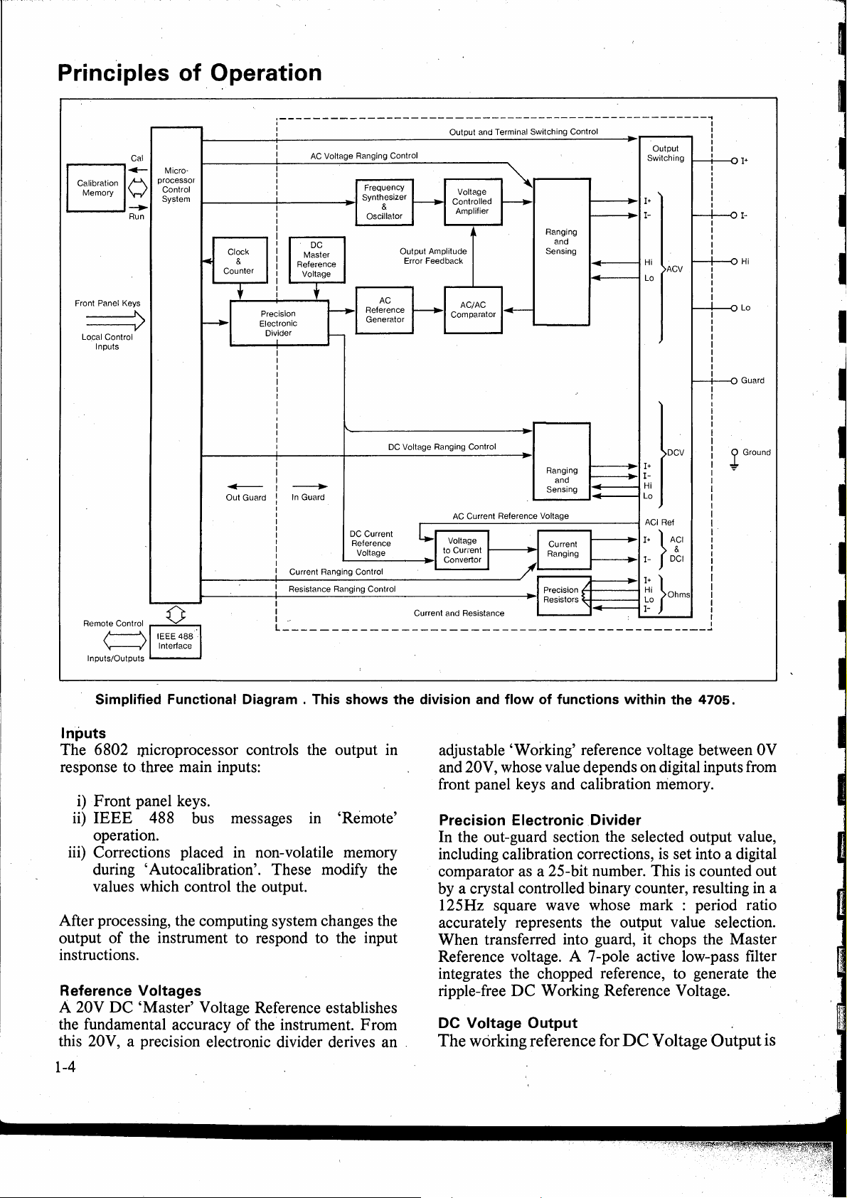
Simplified Functional Diagram . This shows the division and flow of functions within the 4705.
lnputs
The 6802 microprocessor controls the output in
response to three main inputs:
adjustable 'Working' reference voltage between 0V
and 20V, whose value depends on digital inputs from
front panel keys and calibration rriemory.
i)
Front panel keys.
ii)
IEEE
operation.
iii) Corrections placed in non-volatile memory
<luring
values which control the output.
488 bus messages in 'Remote'
'Autocalibration'. The se modify the
Precision Electronic .Divider
In the out-guard section the selected output value,
including calibration corrections,
comparator as a 25-bit number. This
by a crystal controlled binary counter, resulting
125Hz square wave whose mark : period ratio
After processing, the computing system changes the
output
of
the instrument to respond to the input
instructions.
accurately represents the output value selection.
When transferred into guard, it chops the Master
Reference voltage. A 7-pole active low-pass filter
integrates the chopped reference, to generate the
Reference Voltages
A 20V
the fundamental accuracy
DC
'Master' Voltage Reference establishes
of
the instrument. From
this 20V, a precision electronic divider derives an
ripple-free
DC
Working Reference Voltage.
DC Voltage Output
The
working reference for
DC
V oltage
)DGV
%
Ref
} ·i'
DGI
}
Ohms
is
set into a digital
is
counted out
Output
Ground
in
a
is
1-4
Page 11

a stable
resolution between O and
DC Voltage Ranging
Low Voltage Ranges
, range
(+19.99999
working reference. The 1 V and 1
achieved
The 1
DC
voltage, accurately variable
+ 20V.
(100µ.V-
of
the 4 705
is
Full Scale), derived directly from the
by
attenuation:
00m
V range attenuator is also used for 1
10V
+ 1 0V Full Range
00m
at
high
FR).
The
basic
V ranges are
Om
1 m V and 100 µV ranges, and the digital input to the
precision divider is scaled to provide the correct
working reference values:
Range
l0mV
lmV
l00µV
High Voltage Ranges
The 1 00V range
working reference.
AC
up
transformation.
W orking reference values
-2V
- + 2V
-200mV
-20mV
(1
00V
is
a direct amplification
The
1000V range employs step-
- + 200mV
- + 20mV
and 1
000V)
of
V,
the
Quadrature Oscillator
The oscillator' s output frequency
demand, between
l0Hz
and
is
l00kHz,
set close to any
by selectingthe
RC time constants ofits dual integrators; and then by
correcting
to
the actual demand by phasecomparison with the output from, the synthesizer.
The output sinewave purity and constant amplitude
are precisely defined by a sophisticated control loop,
and the RMS value
of
the sinewave is adjusted to be
roughly proportional to the demanded output voltage
data
or current. Timing
synchronize the actions
Generator and
Voltage-Controlled Amplifier (VCA}
AC/
is output from the source to
of
the A C Reference
AC
Comparator.
This has variable gain, amplifying the output from
the Sinewave Source and providing a buffered drive
to the output circuits. Its gain is determined by the
measured difference between the
sensed calibrator output and the
the
VCA
provides the correcti'ng fine adjustment för
values
AC
Reference; so
of
the
RMS
the output amplitude loop.
AC Voltage Ranging
Output Switching.
In
addition to switching
between functions, the output switching circuits
isolate terminals on
Sense and
AC Voltage Output
Guard
The working reference for
stable
DC
voltage, accurately variable at high
resolution between
AC Reference Generator
· The higher accuracy
AC/DC)
is exploited
O UTPUT O FF. Remote/Local
switching is incorporated.
AC
Voltage Output
+ 0.1 V and + 2V
of
AC/
AC
by
converting the
DC.
comparison ( over
DC
Working
Reference into a stepped waveform whose
characteristics match those
of
amplitude
controlled by the
Sinewave Source
Frequency Synthesizer
From
the frequency value set into the
FREQUENCY
this 'Quasi-sinewave'
DC
W orking Reference value.
display, the processor controls the
of
a sinewave. The
is
precisely
MODE/
synthesizer using an encoded 9-bit command. The
synthesizer translates the command into a pulse
train at a crystal-derived frequency between 240kHz
for,
and 4MHz, to be divided down
use as phase-
reference for the Quadrature Oscillator.
N.B.
lf
required, the Frequency Synthesizer, can
toa
be locked
customer's
1MHz
or
10MHz
frequency, input via J53 on the rear panel.
isa
1V
Range
This is the basic
the
AC
working reference is variable between 0.1 V
and 2V RM~, it is compared in
sensed output.
directly to the output
1
00mV, 1 Om
The 1 V Buff er output is reduced
AC
The
1 V Buffer output
V and 1
voltage range
I+
and I - terminals.
mV
Ranges
of
the 4705.
1:
1 ratio with the
is
thus passed
by
precision
As
attenuators before being connected to the terminals, ,
the level being sensed before attenuation.
1
0V, 1 00V
The 1 V Buffer output is amplified on each
ranges. A separate amplifier is provided for the 1
range, the output sense signal being obtained
and 1
000V
Ranges
of
these
0V
at
the
terminals and attenuated before coinparison with the
reference. A common power amplifier is used for
On
the
l00V
both 100 V and 1000V ranges.
Range
the output is fed directly to the terminals, on the
is
1 000V Range the output
On
both ranges, the sensed terminal voltage is
stepped up by a transformer
reduced to the reference lev el by precision attenuators.
Output Sensing
On
the 1 V range and above, the output
the front panel
Hi
and
Lo
terminals. With Remote
Sense selected, these are isolated from
but in Local Sense Hi is internally connected to
and
Lo
to
I-.
As
described above, the lOV, 100V
and 1 0Ö0V ranges' sense signal
is
is
sensed at
I+
and
I-,
I+,
attenuated before
comparison with the reference.
-·-----
1-5
Page 12
AC/
AC
Comparator
The comparator generates an error voltage
proportional to the difference between the RMS
values of the
alternately samples a number
AC
reference and the sensed output. It
of
cycles from its
'Ref
and 'Sense' inputs, computes and integrates the
squares
of
their instantaneous values, and uses a
'Sample and Hold' technique to subtract one from
the other, this being the 'error' voltage to control the
VCA. The loop thus controls the 4 705 output so that
the RMS value
equates to that
DC Current
On changing functions to
Reference voltage
of
the comparator' s sense input
of
its reference input.
DC
Current, the W orking
is
switched to drive a voltage-to-
current converter, and the OUTPUT display legend
is
changed to µA,
is
provided, and the Output lines are fused.
AC Current
An
AC
Current output
current converter. The 100
mA
or A. Over-voltage protection
is
produced by the voltage-to-
µA
and 1 A ranges are
driven directly from the basic 1 V range, and the
others from the 1
achieved
,by
protectiori against over-voltage
OV
range. Range selection is
switching internal shunts. Output
is
provided, and the
output lines are fused. The OUTPUT display legend
is
altered to µA,
mA
or
A.
Autocalibration
By setting the CAL
the rear panel to
·calibrated. (Refer to Section 8). The output value
measured and the microprocessor
ENABLE_
security keyswitch on
ENABLE, the 4705 can be
is
activated, to
is
add any new corrections to factors already retained
in
non-voltai_le
factors are applied in the normal R
Processor
memory. The updated correction
UN
mode.
A 6802-series microprocessor controls the intemal
performance
26K
bytes
2K
bytes
space, and
of
the instrument, employing
of
program memory.
of
memory are used for stack and work
2K
bytes are made non-volåtile by a
battery-pbwered back-up supply, storing calibration
correction factors.
With the exception
ofthe
Power
ON/OFF
switch,
each front and rear panel control provides an input to
the microprocessor system, which translates the
information to command the
4 705 analog and
calibration functions.
The processor also controls the display, the
IEEE
488 Interface Bus and the operation
of
the
restart and error circuitry.
Resistance
Remote Sense. One
resistors
I-,
is
internally 4-wire connected to the I+,
Hi and Lo terminals by operation
of
a set
of
eight precision
of
each
RANGE key. Simultaneously the 4-wire calibrated
value
of
the resistor
is
displayed (OUTPUT
display). Pressing the OUTPUT Zero key connects
a true 4-wire short to the terminals, and the
0 UTPUT display indicates zero. This zero display
value cannot be recalibrated.
Local Sense (Remote Sense LED Unlit).
The
connections to the resistor remain the same, hut the
display value includes the resistance of the
connections form the
Hi
and Lo terminals to the
resistor. The arrangement provides a calibrated
2-wire facility with external connection to the Hi and
Lo terminals. The Zero key shorts the Hi and Lo
terminals,
terminals
. When
4
705
in
this case the resistance between the
is
displayed and may be recalibrated .
n
is
selected from any other function, the
is
forced into Remote Sen se, hut this may be
deselected for 2-wire operation.
1-6
Page 13
SECTION 2 INSTALLATION
This section con~ains information and instructions for unpacking and installing the Datron
Unpacking and lnspection
E very care
to ensure that your equipment will reach you in
perf ect condition.
If
the equipment has been subject to excessive
mishandling in transit, the fäet will probably be
visible as extemal damage to the shipping carton.
the event
cushioning material should be kept for the carrier' s
inspection.
Unpack the equipment and check for extemal
damage to the case, sockets, keys etc.
found, notify the carrier and your sales
representative immediately.
Standard accessories supplied with the instrument
are as described in Section
is
taken in the choice of packing materials
of
damage, the shipping container and ,
If
damage
1.
lt;i
is
Power cable
The detachable supply cable, comprising two meters
of 3-core PVC sheath cable permanently moulded to
. a fully-shrouded 3-pin socket, fits in the
INPUT
home. ·
The supply lead should be connected to a grounded
outlet ensuring that the ground lead
Connect Black lead to Line, White lead to Neutral
and Green lead to Ground. (European: Brown lead
to Line, Blue lead to Neutral, and Green/Y ellow
lead to Ground).
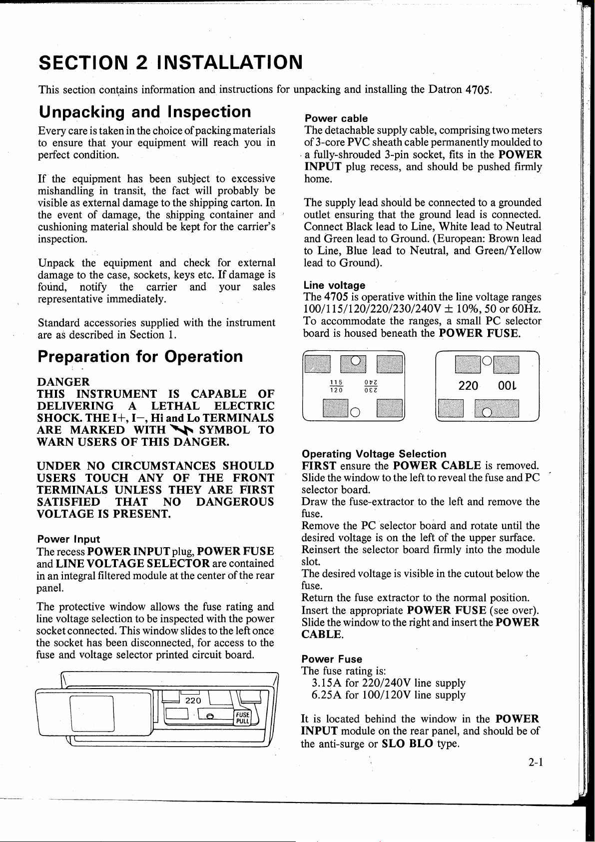
Line voltage
The 4 705
100/l
To
board
plug recess, and should be pushed firmly
is
operative within the line voltage ranges
15/120/220/230/240V
accommodate the ranges, a small
is
housed beneath the POWER FUSE.
+ 10%, 50 or 60Hz.
Preparation for Operation
4705.
is
PC
POWER
co~nected.
selector
DANGER
THIS INSTRUMENT IS CAPABLE OF
DELIVERING A LETHAL ELECTRIC
I+,
I-,
SHOCK. THE
ARE MARKED WITH
WARN USERS
UNDER
USERS TOUCH ANY OF THE FRONT
TERMINALS UNLESS THEY ARE FIRST
SATISFIED THAT NO DANGEROUS
VOLTAGE IS PRESENT.
Power lnput
The recess POWER INPUT plug, POWER
and LINE VOLTAGE SELECTOR are contained
in
an integral filtered module at the center
panel. ·
The protective window allows the fuse rating and
line voltage selection to be inspected with the power
socket connected. This window slides to the left once
the socket has been disconnected, for access to the
fuse and voltage selector printed circuit board.
NO CIRCUMSTANCES
Hi and Lo TERMINALS
~
SYMBOL
OF
THIS DANGER.
TO
SHOULD
FUSE
ofthe
rear
\
220
Operating Voltage Selection
FIRST ensure the POWER CABLE
Slide the window to the left to reveal the fuse and
selector board.
Draw the fuse-extractor to the left and remove the
fuse.
Remove the
desired voltage
Reinsert the selector board firmly into the module
slot.
The desired voltage
fuse.
Retum the fuse extractor to the normal position.
Insert the appropriate
Slide the window to the right and insert the
CABLE.
Power
The fuse rating
3.15A for 220/240V line supply
6.25A for
Fuse
PC
selector board and rotate until the
is
on the left
is
visible in the cutout below the
is:
100/l
20V line supply
POWER
of
the upper surface.
FUSE
OOL
is
removed.
(see over).
PO WER
PC
D
is
located behind the window in the POWER
It
INPUT
the anti-surge or SLO BLO type.
module on the rear panel, and should be
of
2-1
Page 14

WARNING
MAKE SURE THAT ONLY FUSES WITH
THE REQUIRED RATED CURRENT
OF THE SPECIFIED TYPE ARE
REPLACEMENT. THE
FUSES
AND
THE SHORT CIRCUITING OF
USE
USED
op'
AND
FOR
MENDED
FUSE-HOLDERS · SHALL BE AVOIDED,
AND
RENDERS THE WARRANTY VOID.
Bench Mounting
Th,e
instrument
is
fitted with six plastic feet.
It
is
intended to stand flat on a bench, positioned so that
the cooling-air inlet and exhaust apertures are not
obstructed.
( 12 inches) of free space
It
is.
recommended that at least 30cm
is
at the rear.
R~ck Mounting
Option 90 permits the instrument to be mounted in a
standard 19 inch cabinet. ·
Remove the two rear spacers from the case sides by
releasing six screws.
slides to the rear
Fit
the two rack-mounting
of
the case sides and secure using
six of the shorter screws in the option kit.
N.B. The slides may be reversed to give rearward
extension.
Fit
the two rear rack-mounting ears tq the rear ofthe
In
cabinet, with tongues facing forward.
shallow
cabinets it may be necessary to trim the tongue.
CAUTION
is
Assistance
required to fit the 4705 into the
cabinet.
Lift the 4705 into position in the cabinet, locate the
tongues in the slides, and carefully slide backwards
until the front ears hutt up against the cabinet front.
Secure the front ears to the cabinet. Also clear
ventilation for fan
cooli11g
to opera te properly.
I
To Fit Option
90
CAUTION
is
Note that the 4705
front and
rear.
AT NO TIME should the 4705 be
designed to be supported
supported only by the front brackets.
and
account should the upper
lower covers be
removed.
SUITABLE RACK DEPTHS
DEPTH
0 REMOVE
2 OFF 450300 REARSPACERS
6 OFF 611038
M4X12mm
mm
<635
635-735 25-29
735-800 29-31;
SOCKET HD CSK SCREWS
in
<25
FIT
REVERSE RACK
at
On
no
NOTES
SHORTEN REAR RACK
MOUNTING
AS
SHOWN
SLIDES TO EXTEND PAST
EARS
BY DRAWING
MOUNTING
REAR PANEL
0 FIT
2 OFF 450312 RACK
2 OFF 450313 RACK
2 OFF 450314 RACK
12
AS
INSTRUCTED
OFF 611062
MOUNTING
MOUNTING
MOUNTING
M4X8mm
SOCKET HD CSK SCREWS
EAR FRONT
EAR REAR
SLIDE
2-2
@
©
Page 15
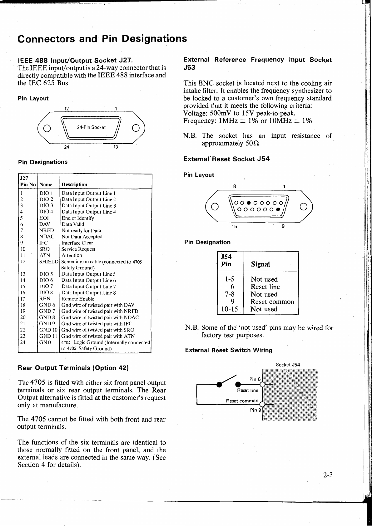
Connectors and Pin Designations
IEEE
488
lnput/Output
The
IEEE
input/ output
is
a 24-way connector that
directly compatible with the
IEC
the
Pin Layout
Pin Designations
J27
PinNo
1
2
3
4
5
6
7
8
9 IFC Interface Clear
10
11
12
13
14
15
16
17
18
19
20
21
22
23
24
625 Bus.
12
\
24-Pin
Socket )
24
Name Description
DIOl
DIO2
DIO3
DIO4
EOI
DAV Data Valid
NRFD
NDAC Not Data Accepted
SRQ
ATN Attention
SHIELD
DIO5
DIO6
DIO7
DIO8
REN
GND6
GND7
GND8
GND9
GNO
GNDll
GNO
Data Input
Data
Data
Data
End
Not ready for Data
Service
Screening on cable ( connected to 4705
Safety
Data
Data Input
Data Input
Data Input
Remote Enable
Gnd
Gnd
Gnd
Gnd
10
Gnd
Gnd
4705 Logic
to
4705 Safety
Output
Input
Output
Input
Output
Input
Output
or
Identify
Request
Ground)
Input
Output
Output
Output
Output
wire
of
twisted pair with DAV
wire
of
twisted pair with
wire
of
twisted pair with NDAC
wire
of
twisted pair with IFC
wire
of
twisted pair with
wire
of
twisted pair with ATN
Ground
Socket
IEEE
Ground)
J27.
488 interface and
13
Line 1
Line 2
Line 3
Line 4
Line 5
Line 6
Line 7
Line 8
(lnternally connected
NRFD
SRQ
is
External Reference Frequency lnput
Socket
J53
This BNC socket
intake filter.
is
located next to the cooling air
It
enables the frequency synthesizer to
be locked to a customer' s own frequency standard
provided that it meets the following criteria:
Voltage: 500mV to 15V peak-to-peak.
Frequency: 1
N.B. The socket has an input resistance
approximately
Externa1· Reset Socket
Pin Layout
MHz
± 1 % or 10MHz + 1 %
500
J54
8
of
ooeooooo
000000•
15
9
Pin Designation
J54
Pin
1-5
6
7-8
Signal
Not
used
Reset line
Not
used
9 Reset common
10-15
N.B. Some
of
the 'not used' pins may be wired for
factory test purposes.
Externa! Reset
Switch
Not
used
Wiring
Rear Output Terminals (Option
The 4
705
is
fitted with either six front panel output
42)
terminals or six rear output terminals. The Rear
Output alternative
is
fitted at the customer's request
only at manufacture.
The
4
705
cannot be fitted with both front and rear
output terminals.
The functions of the six termina
1
ls
are identical to
those normally fitted on the front 'panel, and the
externa} leads are connected in the same way. (See
Section 4 for details).
Reset
common
Socket
J54
2-3
Page 16

DANGIR
THIS
A
llTHAl
HIGH
VOLTAGE
INSTRUMENT
OF DELIVERING
lllCTRIC
...._
..
(
4
THIS CAN KILL !
FRONT
terminals
Full
or
Output
IS CAPABLE
SHOCK
REAR
carry
the
Voltage.
I
I
I
Guard terminal is
sensitive
voltage
It
can
your
Unless
. it is safe
DO
I+
you
NOT
I-
and
Hi
terminals
instrument!
are sure
TOUCH
or
to
damage
to
do
so,
Lo
leads
over -
that
the
2-4
DANGIR
Page 17

SECTION 3 OPERATING CONTROLS
This section summarizes the main operating features
Section 4. ·
Front Panel
MODE FREQUENCY
DANGER "I
HIGH VOL TAGE
~A
I+
I-
Guard
@@@
~{t)4)
\.
-=-
~
FREQUENCY RANGE
Store 100
1aaaaaa
-
F1 . F2
1k
10k
100k
F3
F4
FS
199ggg9
Guard Sen se Spec Error Offset Test
- Remote -
STO
MODE
SET
±0
CAL
of
the 4 705.
For
detailed operating procedures refer to
OUTPUT
,-,,-,nnn;n v
·uuu,uLu,
OUTPUT RANGE
1äBåeieletäå
100
1000
1k0
10k0
100k0
1MO 10MO 100MO
1ra9991~~99
O I AC
FUNCTION OUTPUT
DC
Reset
_:
ON ~ OFF
rdatron"
INSTRUMENTS
4705
AUTOCAL
MULTIFUNCTION
-..
CALIBRATOR
Power
.,
Power-up State
The controls are outlined in blocks, left and right,
The
associated with the appropriate display.
righthand blocks generally deal with function and output
definition, whereas the left-hand blocks are
concemed with frequency, mode and terminal
configurations.
Front Panel Keys
All user commands from front panel keys are
executed through main program firmware. A Key ·
LED
lit signifies that conditions are valid for the
selected operation, and not merely that the key has
made contact. ·
At
any time, the instrument status
of
combination
LED
states, display values and
is
described by the
display messages.
is
Gene·rally, if an invalid condition
selected, an
error message will be displayed and a buzzer will
sound, the command is ignored and the
remains
in
its previous state.
4
705
Power
Switch
WARNING
THE POWER SWITCH SHOULD NOT BE
TO
SET
AND
ON UNTIL THE LINE VOLTAGE
POWER FUSE RATING HAVE BEEN
SELECTED AS DETAILED IN SECTION 2
(INSTALLATION)
When set to the m
Power switch isolates the instrument from the
OFF
position, the 2-pole
supply.
I:]
ON,
When switched to
up, runs a self-test program and
the instrument powers
is
configured into the
following state:
OUTPUT
FUNCTION
OUTPUT
OUTPUT
RANGE
DISPLAY
FREQUENCY
RANGE
OFF
DC
1
.000,000V
Not
selected
MODE/FREQUENCY
DISPLAY
MODE
Guard
Sense
LEDs
Key
Lit
Blank
Not
selected
Local connection ( unlit)
Local connection ( unlit)
OUTPUT
OFF,
DC,
1
3-1
Page 18

QUTPUT
Switching
OUTPUT RANG E
100µ 1m
0
FUNCTION
-
OUTPUT
The 4 705 should normally be connected and set up
with its
Lo
of
MODE
lit.
Pressing the OUTPUT
I - Hi and
'
circuits.
ON/OFF
output off. This isolates the
terminals from their interna! circuitry regardless
RANGE- FUNCTION, FREQUENCY or
sele~tions.
Lo
'fhe
terminals to their energized interna!
10m 100m 10 100 1000
I
AC
I+,
I-,
Hi and
OUTPUT
ON
key connects the
OFF
LED
I+,
is
datrc:n
INSTRUMENTS
4705 , AUTOCAL
MUL TIFUNCTION
CALIBRATOA
r70
Power
••
OUTPUT
Under certain abnorma! conditions which might
compromise safety, the 4705 output will trip off,
accompanied by a
display. Control
keys.
If
the F AIL, 5 message
automatic recovery from the tripped state whether
interna! conditions have or have not returned to
normal.
OFF Trip - Fail 5 Massage
FAIL 5 message on the
is
removed from the front panel
is
present, there
MODE
is
no
OUTPUT
Certain instrument states are prohibited,. and some
transfers between states are restricted by program
firmware.
result in the output being switched
Sectiön 4, Operating Routines.
OUTPUT
On
Output terminals
switch the output on, as labelled. In addition,
polarity may be reversed by using the
step the output across zero value. The
describe the polarity AT THE OUTPUT
TERMINALS,
"error" and "offset" modes these two could be
opposite).
In
functions, the
outputs to appear at the output terminals. The
key will cause the error buzzet to sound and
Error 8 to appear in the
display.
3-2
OFF Default
For
safety reasons some
ON - +
DC
Voltage or Current, the polarity at the
is
determined by the Key
of
these transfers
off. Refer to
+ I + keys to
not on the OUTPUT display. (In
AC
Voltage,
AC
Current and Resistance
ON + key will cause the selected
MODE/FREQUENCY
O N
us~~
LEDs
ON
to
-
Reset Key
The Reset Key has two functions:
1.
It
allows a user to reset the safety trip to test
whether conditions have returned to normal.
they have; the F AIL message will disappear, the
previous instrument state will be restored but
with
OUTPUT OFF, and front panel control
will be returned to
abnorma! the
further attempt may be made after a suitable
interval. The
'Test' mode. ·
2.
It
returns the instrument to power-up conditions
in all cases except the following:
• Self-test mode
• F AIL conditions
• In remote control mode ( where it
inoperative
Other Massages ;
A full list
The fault conditions which generate Fail messages
are analyzed
Handbook.
of
4
705
in
tb-e
user.
If
conditions are still
F AIL state will persist, and a
Reset
LED
is
inoperative except in
is
).
messages appears in Section
the Calibration and Servicing
If
4.
Page 19

FUNCTION
Keys
100µ 1m
Selected
Function
DC
AC
n
DC
AC
OUTPUT RANGE
10m 100m
and I
and I
10 100 1000
Reset
_:
OUTPUT
ON
~
OFF
Specified
Output
DC
Voltage
AC
Voltage ·
Resistance
DC
Current
AC
Current
When
output is automatically set to
from
automatically set to zero.
OUTPUT
new function, the
changing from one function to another the
OFF.
n,
to AC
RANGE
When
or
DC, the OUTPUT value is
If
the corresponding
or value is not available on the
4 705 displays
Error
changing
8 and sounds
its error buzzer.
n selection forces the 4 705 into Remote Sense for
4-wire operation.
OUTPUT RANGE
Each
OUTPUT
selected by the user, setting the legend and decimal
point on the
OUTPUT display to match. Full range
values for voltage and current are marked above the
keys. Nominal values
n function are marked below the keys.
the
OUTPUT RANGE
100µ 1m 10m 100m 1 10
100
1000
Voltage and current ranges are selectable as follows,
the actual output value being selected by use
OUTPUT display tl, keys:
DC
1aaaaaaaa
100
1000
1k0
10kO
100k0
1MO
AC
DC
AC
Voltage
Voltage
Current
Current
Resistance
o
FUNCTION OUTPUT
AC
DC Reset
_:
ON
~
OFF
If
OUTPUT is
remains on unless the change
ranging-up to more than 75V RMS in
DC
on
l00V
range. In these cases OUTPUT
defaults to OFF. Any range selection which would
exceed the internally de
frequency limit
limits are described on page 3-6.
Keys
RANGE
key scales the output as
of
each precision resistor for
100µ,V to 1000V
lmVto
100µ,A to
100µ,A to
lO!l
ON
is
automatically inhibited. These
1000V RMS
IA
IA
RMS
to
lO0M!l
when changing ranges, it
is
to 1 000V range, or
AC
or 1
fin
ed voltage-
of
I0V
the
in
3-3
Page 20

Key
se.ections
100µ
10
lm
100
10m
lk
100m 1
10k
100k
10
lM
100 1000
lOM
lO0M
DC
Voltage
AC
Voltage
DC
Current
AC
Current
Resistance
OUTPUT
Output Resolution
The Output and display
Range
DCV
ACV
DCI
ACI
0 (2-wire)
0 (4-wire)
Display and t
I · 11 11 11 11 9
- -
_,
l00µV
*
l00µA
l00µA
100
lmV
lmV
lmA
lmA
1000
* Error 8
I+
Keys
OUTPUT
- -
are_
resolved as follows:
100µ
10
3½
5½
5½
3½
6½
.lm
100
4½
3½
5½
5½
5½ 5½
6½
l0mV
l0mV
l0mA
l0mA
IkO
~
10m
lk
5½
4½
5½
5½
6½
l00mV
l00mV
l00mA
l00mA
l0kO
100m
10k 100k
6½
5½
5½
5½
6½
6½
lO0kO
6½ 6½
5½
5½
5½
6½
6½
IV
IV
lA
lA
1
lOV
lOV
100V
100V 1000V
1000V
* * *
* .
lMO
10 100 1000
lM
5½ 5½
6½
6½
·*
lOMO
lOM
6½
6½
6½
l00MO
100M
6½
5½
6½
6½
*
The O
which always indicate the correct units for the Range
and Function selected.
Output and Display Control
Each
display digit above
the display may be set within the range permitted by
the function selected.
key adds 1 to its digit: pressing the
If
also changed by the same increments as the display
( subject to the instrument interlocks
On O ranges, only the overrange t I t keys are
operative. These duplicate the action
Range/Zero Keys.
The Resistance value displayed
value
the nominal value
periodic calibration. The value displayed depends
on the selection
3-4
UTPUT
vertical pair
display
of
it.
Each
is
supplemented by legends,
+ I + keys is assigned to the
Thus the value registered on
momentary press
t key subtracts
OUTPUT
of
is
ON,
the Output terminal value is
).
is
the calibrated
the standard internal resistor selected ( not
).
This may · be updated
of
Local (2-wire) or Remote (4-
of
the Full
of
the •
<luring
1.
wire) Sense, and should be recalibrated in the
correct Sense mode (See Section
Auto-1 ncrement/Decrement
When a + I t key is pressed for more than ½ second,
is
its digit
approximately 3 digits per second until the key is
released.
Overflow and Underflow
As a digit is stepped from 9 to 0, the value ofthe next
higher-order digit
0 to 9 decreases the value by
therefore acts as a counter, with full 'carry' and
'borrow' action.
Range of Adjustment for DC Functions
The
+It
minimum
l00mV
for Current Ranges. The 1 00µV Range has a Full
Scale
ranges are truncated.
increased or decreased
is
increased by
keys adjust the readings between a
of
0000000
- 100V and between
of
1100.000; the 100µ,V,
and 1999999 full scale on
8).
at
a rate
1.
Stepping from
1.
The whole display
000000
and 199999
' . l
lmV
and lOmV
of
Page 21

Range
of
Adjustment
for
AC
Functions
The l I t keys adjust the reading between a minimum
of009000
of
199999 full scale on 1
Ranges. The 1000V. Range has a Full Scale
1100.00; the
N.B.
There
(9%
ofNominal
lmV
is
no range
and
Range), and maximum
00m
V.....,... 1 00V
l0mV
of
ranges are truncated.
adjustment on Resistance
and Current
of
functions.
Leading Zeroes
For
fractional readings, a leading zero is presented to
of
the left
except for
lm
the decimal point to emphasise its position,
O
and
UTPUT
1.
RANGE
selections
output terminals.
AC
Voltage - an intemal short circuit is connected
across the output terminals.
DC
and
AC
Current - output terminals are opencircuited.
On
n ranges in Remote Sense with
OUTPUT
ON,
the Zero key connects a true 4-wire intemal short
circuit to the
With
Remote Sense
OUTPUT
is connected, but the actual resistive value
terminals as shown below.
LED
UNLIT,
the same short
of
this
short may be calibrated ( See Section 8 and diagram
below).
I+
I+
DC ZERO and polarity. On DC voltage and current, a
is
polarity sign
present except
at
zero. The numerical
display represents the rriagnitude of the output.
. As the display value is stepped to zero, the polarity
sign disappears, and the opposite sign appears as
stepping continues in the same direction.
0
UTPUT
is
O N
<luring
the sequence, the change in
If
the
output polarity is signalled by a changeover from one
polarity
N.B.
If
ON
the 4
LED
705
to the other.
is
in Offset Mode, with an offset
present, the display and output zeroes do not
coincide.
positive sign on the display, and the
LED
When using the
It
is therefore possible to have a
lit; and vice-versa.
+ I , keys or Zero key to obtain a
ON.:_
zero, the polarity is not changed over and the, same
OUTPUT
ON
LED
remains lit. The polarity
LEDs
change over only when the opposite polarity appears
at the output terminals.
Full Range Key
When the Full Range key
reverts to the nominal value
OUTPUT
is
already
ON,
is
pressed,the display
of
the range selected.
Jf
the terminal value follows
the display value· unless: ·
·
1.
The combination of output voltage and frequency
would exceed the instrument' s intemally defined
limits. (Refer to Section 6).
Hi
I
'Remote
Deselection of Zero
The size
significant. A half-size
'Zero
Sense'
in '
4705
True
4 - Wire
in
of
the characters on the 'Zero' display is
Ohms
Zero
AC Functions ·
·'O'
above any +
Lo
I-
14-w;:e
-~
Ohms
1,
key
indicates that it cannot be used to desetect Zero,
because it increments values which are less than
10%
of
nominal range.
Any
+ key with a full-size
'O'
above it ( and any key to its left) deselects Zero and
adds its increment.
Selection of High Voltage Outputs
The 4
705
is capable
of
delivering
LETHAL
output
voltages so program interlocks are used to ensure
that users do not inadvertently select outputs in
excess
of 1 I0V
in
DC
or 75V RMS in AC. Details
of the High Voltage selection procedure are given in
Section
4.
2.
Offset or Error Mode
off set or gain error
is
selected: the user-input
is
not cancelled from the
output.
Zero key
This reduces the display value to zero.
is
ON, the terminal value
DC
Voltage - an active zero
is
also set to zero:
is
presented to the
If
OUTPUT
Frequency
The
AC
voltage output of the 4705 extends from
0Hz
to 1
MHz
in
five
1
a resolution of 1 %
five
Any
frequency values within the range
overlapping decade ranges, at
of
nominal Frequency Range.
instrument can be stored in volatile memory.
of
the
3-5
Page 22

FREQUENCY RANGE keys
Auto-1 ncrement/ Decrement
When a +
digit is increased or decreased
approximately 3 digits per second until the key is
released.
Overflow and Underflow
As a digit is stepped from 9 to 0, the value ofthe next
higher-order digit
0 to 9 decreases the value by
therefore acts as a counter, with full 'carry' and
'borrow' action.
1,
key is pressed for more than ½ second its
at
a rate of
is
increased by
1.
Stepping from
1.
The whole display
Guard Sense Spec Error Offset Test
- Remote -
Decade Ranging
Generally, selection
frequency by a whole number
ranging-up from a frequency -between lOHz and
30Hz, or ranging-up to the
decade frequency would have been higher, causes
Error 7 to be displayed and buzzer to sound.
Selection of Nominal Range Value
Once a Frequency Range has been selected, it can be
set to its nominal value by re-pressing its key.
FREQUENCY DISPLAY
STO
SET
MODE
of
a new range changes the
MODE FREQUENCY
/
I •
±0
l00kHz
/7
/7
LI
LI"'
of
range when the
GAL
decades; but
k
Autoranging
Stepping the frequency beyond the span
automatically switches range up or down, but further
steps are inhibited until the • or
_ key could be below a decimal point). When the
range-change occurs, the alarm buzzer sounds and
FREQUENCY display is blanked for
the
approx. 1 second.
is
When the display
remembered the last frequency on the old range, and
sets the new range to its next incremental frequency
in the original direction. After releasing the original
key, stepping-can be continued to any increments
the new range.
Autorange Limits
The 4705 displays an Error 7 and sounds its buzzer
when any attempted frequency increment or
decrement is made which would produce an invalid
of
combination
or FREQUENCY. Neither will it incremen'.t or
decrement to a frequency beyond the limits
next frequency range up or down.
FUNCTION, OUTPUT RANGE
reinstated, the 4
t key is released ( the
of
a range
705
of
has
of
the
Il
Resolution
The output frequency
the selected FREQUENCY RANGE nominal
value, matching the display resolution. Legends are
appended on the display as appropriate,
leading zero is presented to the left of the decimal
point for fractional values.
FREQUENCY t lf Control
Each vertical pair
display digit above
is
the display
Each momentary press of the • key adds 1 to its digit,
and each
output frequency
increments as the display ( subject to the instrument
interlocks
inactive. ,
adjusted by manipulation ofthese keys.
t key subtracts
).
Keys below decimal points are
is
adjustable in steps of 1 %
Keys
of
+
1,
keys
is
assigned to the
it.
The frequency registered on
1.
If
OUTPUT
is
also changed by the same
is
ON, the
of
å.nd
3-6
a
_ combinations
· selected.
OUTPUT/FREQUENCY
AC Voltage and Frequency
Under most conditions, the output amplitude and
frequency are adjustable throughout their full
scales:
Voltages - from
Frequencies - from lOHz to
On
the
l00V
of
voltage and frequency cannot be
The diagram below illustrates the boundaries.
The 1
comparison.
The
combination outside these constraints. The
temporary message
approximately 1 second before reverting to the
original display.
0V
Range span is also shown for
4
705
refuses to select any Voltage/Frequency
CONSTRAINTS
90µ,V
to 1100V RMS
lO0kHz.
and 1000V Ranges, certain
Error 7
is
displayed for
Page 23
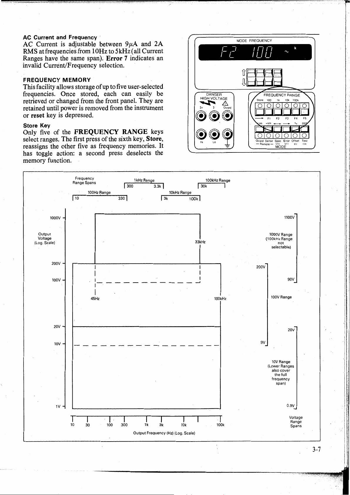
AC Current and Frequency ·
AC
Current
RMS at frequencies from 1
Ranges have the same span).
is
adjustable between 9µA and
0Hz
to 5 kHz ( all Current
Error 7 indicates an
invalid Current/Frequency selection.
2A
MODE FREOUENCY
1=2
IDL7
~
k
FREQUENCY
This facility allows storage
MEMORY
ofup
to
five
user-selected
frequencies. Ortce stored, each can easily be
retrieved or changed from the front panel. They are
retained until power is removed from the instrument
or
reset key
is
depressed.
Store Key
Only
five
of the FREQUENCY RANGE keys
select ranges. The first press
reassigns the other
five
ofthe
sixth key, Store,
as frequency memories. It
has toggle action: a second press deselects the
memory function.
1000V
Output
Voltage
(Log. Scale)
Frequency
Range
110
Spans
100Hz Range
1kHz Range
I 300 3.3k I
330 I
10kHz Range
!
3k
DANGER
HIGH VOLTAGE
~&
I+
I·
Guard
®®®
~~,
100kHz Range
I
3ok
10Dkl
33kHz
I
Guard Sense Spec Error Oflset Test
-
Remote-
sro
sr,
±o
MODE
1000V Range
(1
OOkHz
not
selectable)
1100V
Range
C.At
200V
100V
20V
10V
1V
200V
SOV
------------'
9V
(Lower
100V Range
20V
10V Range
Ranges
also
cover
the
full
frequency
span)
0.9V
Voltage
Range
Spans
45Hz
I
10
30
I· I
100 300
Output
1k
Frequency
I I
3k
(Hz) (Log. Scale)
10k 100k
100kHz
.1
3-7
Page 24
F 1-
F5
M emory keys
When the Store
LED
is
ON, these keys select
individual memory locatiorts.
N.B.' Although the
FREQUENCY
RANGE
keys
double as memory selectors, this does not
imply that a particular memory can only
accept frequencies from its key' s range.
It
is
emphasized that any displayable frequency
can be stored in any of the
Power-up Default
five
locations.
Because the stores are volatile, the following default
frequencies are stored in the
each time the
4705
is
five
memory locations
powered-up:
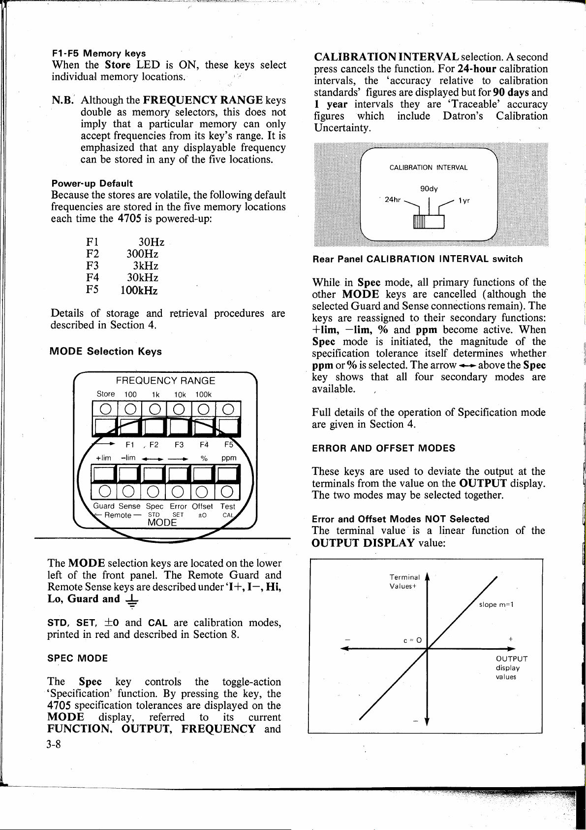
CALIBRA
press cancels the function.
TION
INTERVALselection. A second
For
24-hour calibration
intervals, the 'accuracy relative to calibration
standards' figures are displayed but for
90
days and
1 year intervals they are 'Traceable' accuracy
figures which include Datron's Calibration
Uncertainty.
CALIBRATION INTERVAL
90dy
'24hr~1yr
Fl
F2
F3 3kHz
F4
F5
Details
described
MODE
30Hz
300Hz
30kHz
lOOkHz
of
storage and retrieval procedures are
in
Section
Selection Keys
FREQUENCY RANGE
Store 100
4.
1k
10k 100k
0
Guard Sense Spec Error Offset
Remote -
STO
MODE
SET
±0
Rear Panel CALIBRATION INTERVAL switch
While in S pec mode, all primary functions
other
MODE
keys are cancelled (although the
of
the
selected Guard and Sense connections remain). The
keys are reassigned to their secondary functions:
+ lim,
Spec mode
-lim,
% and ppm become active. When
is
initiated, the magnitude
of
the
specification tolerance itself determines whether
ppm or %
is
selected. The arrow .,_... above the S pec
· key shows that all four secondary modes are
available.
Full details
are given
ERROR
in
AND
the operation
Section
OFFSET
4.
of
MODES
Specification mode
of
These keys are used to deviate the output at the
terminals from the value on the
OUTPUT
display.
The two modes may be selected together.
Error and Offset Modes
The terminal value ·
OUTPUT
DISPLAY
NOT
Selected
is
a linear function of the
value:
The
MODE
left
of
Remote Sense keys are described under
Lo, Guard and
STD, SET, +o and CAL are calibration modes,
printed
SPEC
MODE
selection keys are located on the lower
the front panel. The Remote Guard and
'I+,
I-,
Hi,
~
in
red and described
in
Section
8.
The S pec key controls the toggle-action
'Specification' function. By pressing the key, the
4
705
specification tolerances are display ed on the
MODE
FUNCTION,
display, referred to its current
OUTPUT,
FREQUENCY
and
3-8
Terminal
Values+
+
OUTPUT
display
values
Page 25

Error mode selected
Terminal
Values +
~
±10%
~
displayed
Value
of
Terminal
Values+
+
OUTPUT
display
values
Full details
in
~ection 4.
of
the operation
of
Error mode are given
Offset mode selected {DC Functions only)
In
Offset mode, the intercept ( c) may be adjusted to
any value within the Offset limit.
Offset Limits: 100µ,V and
Other Ranges:
lmV
Ranges: +200µ,V.
+2%
of
Full Range
value.,
·Terminal
Values+
offset
selected-
TEST
MODE
Test mode selected
Full details
in Section
1+,
1-,
4.
Hi,
ofthe
operations in Test mode are given
Lo,
Guard
and~
(Ground) Terminals ·
Local and Remote Switching
MODE FREQUENCY
not
selected +
OUTPUT
display
values
selected
+.
Output
display
values
Offset and Error
Mode
Combination.
Offset cannot be selected or deselected when the
4 705
is
already
The intercept (
then the slope (m)
Full details
combined mode are given
in
Error
c)
is
established first
is
of
the operation
Mode.
adjusted
of
in
in
Offset mode,
in
Error
mode.
Error, Offset and the
Section
4.
DANGER
HIGH VOL TAGE
~&
I+
I·
Guard
®®®
FREQUENCY RANGE
Store 100
121aaaaa
-
+-hm
1999t51199
Guard Sense Spec Error
-
-lim
Remote-
F1
F2 F3 F4
,..___.
",JIJ
MODE
1k
10k 100k
---
-..r
r
0
Olls~I
FS
o
ppm
Test
These terminals are located on the lower left of the
Front Panel.
1+
and I-Terminals
The output from the interna! power circuits
· delivered to the
I+
terminal, I-being its Return
Analog Common.
Hi and
Lo
Terminals
These terminals provide a differential input to the
amplitude sensing circuitry.
is
3-9
Page 26

Remote Sense
The Remote Sense key has 'toggle' action.
Successive presses altemate between
OFF. '
N.B. Sense connections can only be switched
with OUTPUT OFF.
ON
and
For
Voltage outputs
should be attached to the Hi and Lo terminals.
Various configurations of
detailed
in
Section
in
local sense the two leads
4
705
load connections are
4.
The specified voltage output
produced either at its output terminals (Local Sense
for high impedance loads) or at the load terminals
(Remote Sense for cases in which lead resistance
and load impedance produce a significant effect).
With Remote Sense OFF, the
isolated, and the voltage output
terminal. ·
With Remote Sense ON, the output voltage
across the
sensed extemally, using leads connected to the
and Lo terminals. ·
Remote Sense
ranges.
On Ohms ranges, Local Sense
connections, and· Remote Sense for 4-wire.
(Changing FUNCTION into
Remote Sen se, hut this may be deselected for 2-wire
operation). The Remote Sense
indicates the true connection:
Lit
I+
and I - terminals only, and must be
is
not available on lO0µV - lO0mV
It
is
not applicable to Current outputs.
= Remote; U nlit = Local. .
of
the 4
705
may be
I+
terminal
is
fed to the
is
used for 2-wire
is
is
Hi
fed
Hi
n forces the 4705 into
LED
always
Guard Terminal
The Guard terminal
interna! guard shields:
Remote Guard
The Remote Guard key has 'toggle' action.
Successive presses altemate between
OFF.
With Remote Guard OFF, Guard
connected to the I - terminal.
With Remote Guard ON, the interna! link to
is
removed. The . Guard terminal can then be
connected extemally to reduce common mode
interference.
Ground Terminal
The
-:-
( Ground) terminal connects directly to the
4
705
in.tema! Ground shields and to Safety Ground
via the power-cable.
Output Connections
Connections to the output terminals may be made
either with leads or via a shrouded connector.
3-10
is
permanently connected to the
ON
is
intemally
and
I-
Page 27

Rear Panel
(Shown with alternative Rear Output terminals).
r/
u
..._
-----
MODEL
SERIAL
No
RtNEW
BATT
AT
TS
See
INPUT VDL
FREOUENCY 48-62Hz
POWER 400VA
OPTIONS
POWER
INPUT
IJr&J
Power
Approx
POWER FUSE
11
D
lnput
,,,
J27
IEEE
488
~,-
CALIBRATION
INTERVAL
90<1y
24hr
CALIBRATION
ENABLE
*
""~
7~
1 yr
SH1AH1T6
TE0L4LE0'
SR1RL2PPIJ'
DClDT~C~El
•
S53
lllllllCJ
OFF
DN
J53
0
-----
rJ
w.-.-:;
7 r
\..
\..
DANGER HIGH VOL
....
;
~i~
TAGE
_&
~
j)
i i
'
.,
L
~
-
-
"'-
)
~
POWER
INPUT
The recessed POWER INPUT plug, POWER
FUSE
located in the center
within a single moulded unit. Details
selection ofline voltage and
REAR
and LINE VOLTAGE SELECTOR are
'Of
the rear panel, contained
of
connections,
fuse
are given in Section
OUTPUT
ALTERNATIVE (Option 42)
2.
This can be incorporated at manufacture, to provide
six output terminals on the rear panel instead of the
six on the front. Their functions and connections are
identical.
SOCKET
(Externa! Reference Frequency lnput)
['-..
J53
This BN C socket is located next to the cooling air
It
intake filter.
may be used to lock the internal
frequency synthesizer to a customer' s own
frequency standard. Voltage and frequency criteria
are given in Section
located above this socket
facility.
is
Ifthe
switch
not present, error message 'Error EF' is
2.
An
on-off switch; S53,
is
provided to enable this
is
on and an external frequency
displayed.
SOCKET
The
J27
{IEEE
IEEE
488 Input/Output(D-type) socketJ27
488
lnput/Output)
a 24-way micro-ribbon connector that
compatible with the
IEEE
48 8 interface and the
IEC-defined system.
·
127
is
located at the top
with the
IEEE
488 address switch. The pin layout
of
the rear panel, outlined
and designations appear in Sections 2 and 5.
IEEE
488
ADD
The 4
IEEE
ADDRESS
5 4 3 2 1
705
may be addressed for use on the
48 8 interface bus. The address settings are
SWITCH
given in Section 5.
is
directly
'O'
. '1'
)-]t
is
SOCKET
This D-type socket
J54
(Externa! Reset)
is
located next to the optional
rear output connectors. It may be used to input an
external reset to restore the
4705 to its power-up
state of DCV, 1 V Range etc. ifrequired. Pin Layout,
Pin Designation and Switch Wiring details are given
in
Section
2.
3-11
Page 28
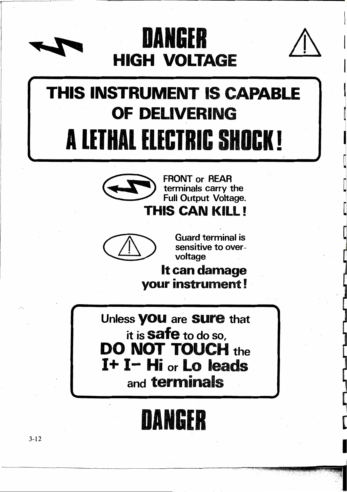
I
r
THIS
...
HIGH VOLTAGE
INSTRUMENT
OF DELIVERING
A
llTHAl
DANGIR
IS CAPABLE
lllCTRIC
SHDCK
&1
-~
!
r
..
Unless
it
DO
I+
NOT
I-
and
Guard terminal is
sensitive
voltage
It
can
_
your
you
is safe
instrument!
are sure
to
TOUCH
Hi
or
Lo leads
terminals
to
over -
damage
that
do
so,
the
·
3-12
DANGIR
Page 29

-
_:-_-
-- - -----. ---~-·
·---~·
·----:-·---··----~
--~·::_-~--:--:--:--=-:s::..:.:··---·~---
---~-~-
..
-.·__:_-.--.~---·-··-~-.:___:...:.-~---~-----
,.c..-·
SECTION 4
USING
THE DATRON
Preliminaries
Before using the instrument it is important that it has
been correctly installed as detailed in Section 2.
Limiting Characteristics
The following details are given in Section
Function
All functions
DC
Voltage
AC
Voltage
DC
Current Maximum load resistance and
AC
Current
Resistarice
Characteristics
Peak terminal voltages
Output · resistance and current limit
Output resistance and current
limit; capacitive loading limits
maximum compliance
Maximum load resistance and
maximum compliance
Maximum currents and accuracy
de-rating factors
6:
4705
UNDER
USERS TOUCH ANY OF THE FRONT (OR
REAR) PANEL TERMINALS UNLESS
THEY ARE FIRST SATISFIED THAT NO
DANGEROUS VOLTAGE IS PRESENT.
CAUTION:
THE
THE
DETAILED IN THIS
PLACED ADJACENT
THAT ARE SENSITIVE
CONDITIONS.
REFER
I nterconnections
IMPORTANCE OF CORRECT
CONNEC!IONS
NO CIRCUMSTANCES
A SYMBOL IS
USER
OF SPECIAL PRECAUTIONS
USED
HANDBOOK
TO
TO
SECTION 6.
SHOULD
TO
REMIND
AND
TO
TERMINALS
OVERVOLTAGE
IS
-
'j
The
4
705
is
designed to be Class 1 equipment as
defined in
concerning safety requirements.
Protection is provided by a direct connection via the
power cable from ground to exposed metal parts and
interna! ground
The line connection must only be inserted in a socket
6btlet provided with a protective ground contact, and
continuity
between the socket and the instrument.
IEC
Publication 348 and
screens_.
of
the ground conductor must be assured
UL
1244,
WARNING:
ANY INTERRUPTION OF THE PROTECTIVE
GROUND
CONDUCTOR
INSIDE
OR
OUTSIDE THE INSTRUMENT, OR
DISCONNECTION OF THE PROTECTIVE
GROUND
TERMINAL MAY MAKE THE
APPARATUS DANGEROUS. INTENTIONAL
INTERRUPTION IS PROHIBITED.
THE TERMINALS MARKED WITH THE
~
SYMBOL CARRY THE OUTPUT OF
THE 4705. THESE TERMINALS
TÖ
OTHER CONNECTIONS
UNDER
TEST COULD CARRY LETHAL
THE LOAD
AND
ANY
VOLTAGES.
The 4705 has been designed for use as an accurate
source for precision calibration. T o match the
externa! circuitry to its superior specification, it is
essential to take great care in making connections to
the load.
SOURCES OF ERROR
Thermal
These can give rise to series (normal) mode
interference, particularly for low voltage outputs,
and where large currents have a heating effect at
thermo-electric junctions. Draughts can cause
unbalanced cooling in an otherwise thermoelectrically balanced measuring circuit.
E-M
N oisy or intense electric, magnetic · and
electromagnetic effects in the vicinity can disturb the
measurement circuit.
Some typical sources are:
- Proximity
- Fluorescent lighting.
- Inadequate screening, filtering or grounding of
- Transients from local switching.
- Induction · and radiation fields of . local
- Excessive common mode voltages between
EMFs
I nterference
of
large electric fields.
power lines.
E-M transmitters.
source and load.
4-1
----------------------------------11111!!!1111--
Page 30

The disturbances may be magnified by the user' s
hand capacitance. Electrical interference has
greatest effect
Separation
of
in
high . impedance circuits.
leads and creation of loops
in
the
circuit can intensify the disturbances.
Lead I mpedance
The impedance
of
the connecting leads can drop
significant voltages between the source and load, and
generate adverse phasing effects particularly if the
leads · are long or the current in them
Lead lnsulation Leakage
is
high.
This can cause significant errors in measurement
circuits at high voltages. Some insulating materials
suffer greater losses than others e.g. PVC has more
leakage than
A,.VOIDANCE
Thermal
PTFE.
TACTICS
EMFs
Screen thermal junctions from draughts.
Allow time for thermal equilibrium to be reached
before taking readings.
U se conductors, joints and terminals with a good
margin
of
current-carrying capacity.
A void thermo-electric junctions where possible:
e.gi
Use untinned single-strand copper wire
of
high
purity. Avoid making connections
through Nickel, Tin, Brass and Aluminium.
oxidation
is
a problem use gold-plated copper
If
terminals, and replace the terminals before the
plating wears
off.
Ifjoints must be soldered,
lowthermal solders are available, but
crimped joints are preferred. U se low-thermal
switches and relays where they form part of the
measuring circuits.
Balance one thermal
EMF
against another in
opposition, where possible, ( switch and relay
contacts, terminals etc.)
r'\
E-M
"
I nterference
Choose as 'quiet' a site as possible ( a screened cage
may be necessary if interference
is
heavy).
Suppress as many sources as possible.
Always keep interconnecting leads as short as
possible, especially unscreened lengths.
Run leads together as twisted pairs in a common
screen to reduce loop pick-up area, but beware of
leakage problems and excessive capacitance.
Where both source and load are floating, connect
1-
to ground at the source to reduce common mode
voltages.'
at the
load~
Use ·4-wire connections for values
of
resistance below 1 kO.
Lead lnsulation Leakage
Choose low-loss insulated leads -
PTFE
is
preferred to PVC.
When running leads together in screened pairs,
avoid large voltages between leads in the same
screen, especially if using PVC insulation.
Remote/Local Sense Cor:,figurations
The 4
705
terminals are configured as follows:
Voltage ranges
lOOµV,
lmV, lOmV,
lOOmV
- Local sense only.
lV,
lOV,
lOOV,
- user selects ·Local or
1000V
Re_mote
sense.
All Current ranges
- Local sense only.
All Resistance ranges
- Remote -Sense gives 4-wire
connection.
- Local Sense provides 2-wire
connection capability.
The key
N.B. When changing to O function, the
LED
indicates the true connection:
Lit=
Remote, Unlit = Local.
4705
is
automatically forced into Remote Sense for
4-wire operation.
4705 -CONNECTIONS
General Considerations
The choice
of
connection method
TO THE LOAD
is
influenced by
several factors:
a.
Loading Effects
4-wire connections should be used for low load
impedances.
For
high impedance loads, 2-wire
connections can be employed.
The ratio : Total Lead Resistance
Load Resistance
gives the approximate error for 2-wire connection
at low frequencies.
e.g. Two ½-Ohm leads with a load
produce an error of approx. 1
of 1 OOkOhms
Oppm.
Il
I
Lead I mpedance
Keep all leads as short as possible. U se conductors
with a good margin
of
current-carrying capacity. U
se
Remote Sense and 4-wire connections where
necessary to establish the
4
705
output specification
4-2
b.
Noise and Output Level
Providing the
E-M
environment
is
reasonably
quiet, interf erence due to noise pickup in the load
connection
is
insignificant for outputs of more
Page 31

than about 100m
V,
so unscreened leads can be
used. But at lower signal levels, or in noisier
environments, it
is
advisable to use screened
cable.
c.
Common
Mode
Disturbances
When in Local Guard, the guard shields and
tracks for the Sense circuitry are connected
intemally to
the 4
705
'I-',
the low impedance terminal
output power source. This classical
connection effectively guards out intemal
common mode disturbances.
disturbances it
is
advisable to make only one
To
reduce extemal
ground connection to the measurement circuit,
and in the case
of
a guarded D
MM,
to make use
its externa! guard facilities. Also, where a linepowered load (such as a
DMM
being calibrated)
has a ground connection, it should be to the same
line ground as the
d.
High Frequency Effects
i.
Voltage. Up to lO0kHz,
is
it possible to use pairs
provided
thatthe
4
705.
for
outputs above 100m
of
unscreened wires,
E-M.environment is quient. Twist
or run leads together; keep length less than 1 meter.
of
of
Setting Priorities
Because
a.
the variety of environmental conditions and loads
of:
likely to be ,encountered when using the
b.
the extensive set
of
combinations
of
outputs from
the instrument, and
c.
the accuracy required;
it
is
unrealistic to describe a definitive 'best' general
of
method
Combinations
connection to the load.
of
the above factors can lead to
conflicting requirements, and users may be faced
with a choice between methods. In these cases it
sometimes necessary to arrive at a compromise
solution by setting priorities.
Suggested Lead Connections for the
Six suggestions for connecting the 4
4705
705
are illustrated in the following pages 4-4 and 4-5.
Each
has found use with the combination
described, and together they cover the majority
predicted requirements.
V,
4705,
is
to its load
of
factors
of
ii. Current. Above about
lkHz,
with low output
currents, high lead capacitance can introduce
shunt errors.
To
reduce these errors, the leads
should be kept as short as possible, and be of lowcapacitance.
e. DANGER.
THE 4705 OUTPUT CIRCUITS ARE NOT
INTERN ALL Y CONNECTED
'\
GROUND. USERS ARE STRONGLY
TO
ADVISED
,EXTERNALLY
(PREFERABLY
JUNCTION),
USED
THIS
AND
ON
THE
ELIMINATES
I-
CONNECT Lo OR
TO
AT
THEIR COMMON
WHEN
FLOATING
IO0V
THE
OR
THE
4705
IO00V
RISK
TO
GROUND
IS
RANGE.
VOLTAGE.
TO
1-
TO
BE
OF
HIGH
Lo
4-3
Page 32

Typical Lead Connections
Voltage and Resistance Outputs
CAUTION: All leads and cables must be proofed
to ·at least 2kV.
Simple
Use for many applications where:
The voltage drop in the leads
The
Extemal common-mode voltages are insignificant.
U se for measurements in the following ranges:
N.B.
Select Local Sense and Local Guard.
Keep leads as short as possible, ( not longer than 1
meter-twisted pair
On 100V
2-wire
E-M
Voltage
Frequency F
Resistance
After selecting
Connection
environment
DCV
ACV
< 1 00kHz
lkO
is
'quiet'.
> 1 00m V
> lO0mV
< R <
n,
Remote Sense must be
cancelled for 2-wire operation.
is
preferable).
/lO00V
Ranges, Ground the Lo line for Safety.
is
insignificant.
lMO
Note: Refer also to reactive load specifications m
Section 6.
@ @
I+
4705
Terminals
Load
Terminals
_______________
~~----0
Hi
I-
Lo
/@
/ Gu Local Guard
/ Local
Gu Local Guard
Sense
_
Screened
2-wire
Connection
Use where:
Sensitive measurements are being made.
. The
E-M
environment
is
relatively 'noise'.
Extemal common-mode voltages are significant.
U se for measurements in the following ranges:
Voltage
Frequency F
Resistance 1
After selecting
DCV
;>
lOµV
ACV
> 90 µV
< 1
OOkHz
kO
< R < 1
n,
Remote Sense must be cancelled
MO
for 2-wire operation.·
Select Local Sense and Local Guard.
Keep leads as short as possible, ( not longer than 1
meter).
On 100V/1000V Ranges, Ground the Lo line for Safety.
S~reened
4-wire
Connection using Coaxial cable.
Use where: ·
is
The load resistance
significant voltage drop
low enough to cause a
in
the output
connection.
Sensitive measurements are being made.
The E-M environment
is
relatively noisy.
4705
Externa! common-mode voltages are
significant.
U se
for
measurements in the following ranges:
DCV
ACV
<
> 90m V
;>
90mV
lOOkHz
Voltage
Frequency F
Resistance Not appropriate
Select Remote Sense and Local Guard.
Keep leads
as
short as possible, ( not longer than
1 meter).
On 100V /lO00V Ranges, Ground the Lo line for Safety.
@ @
4705
Terminals
Load
Terminals
________________
Terminals
Load
Terminals
________________
I+
Hi
Hi
I-
Lo
Lo
/@
/ Gu
/
/
~
Gu
":'
Gu R,emote Guard
Local Guard
Sense
Local
Optional
Remote Guard
_
Local Guard
Sense
Remote
Optional
_
4-4
Page 33
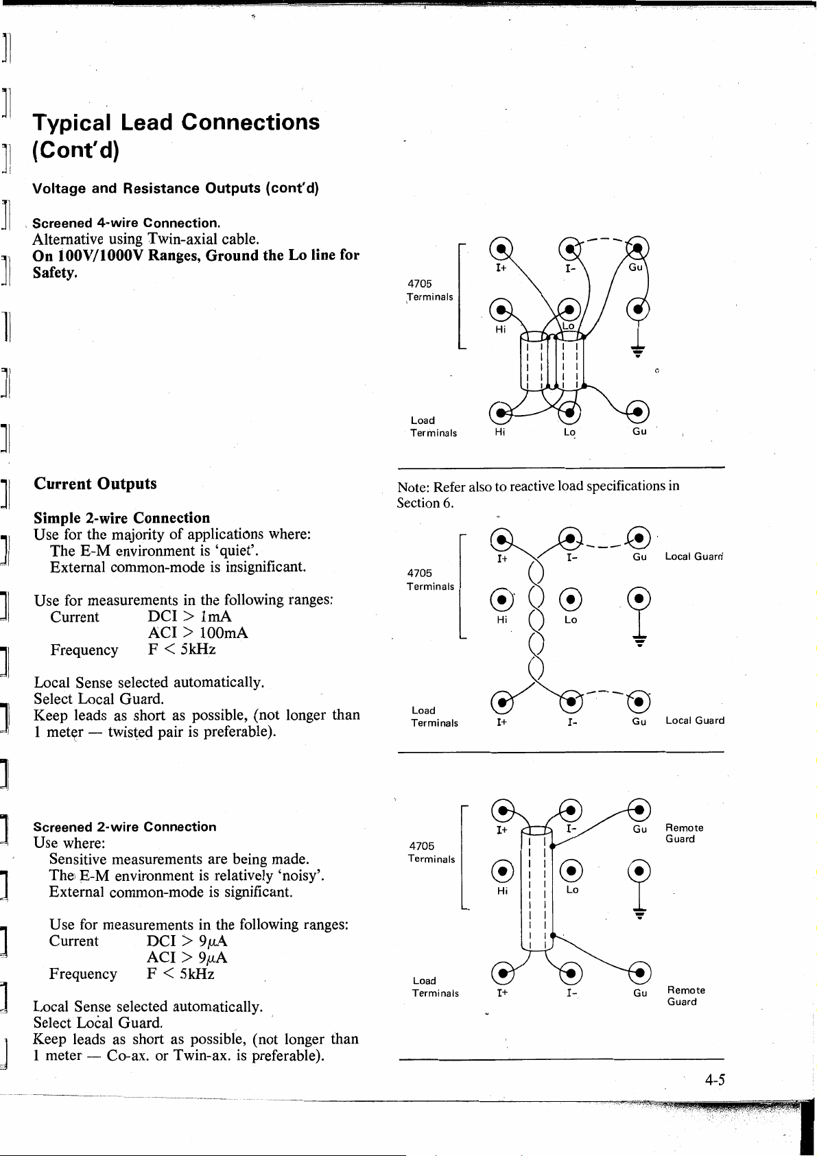
]1
]1
Typical
(Cont'd)
]]
.,
Lead Connections
~•
i
--------·-
Voltage and Resistance Outputs ( cont'
]I
, Screened
Alternative using Twin-axial cable.
On 100V/1000V Ranges, Ground the Lo line for
Safety.
]l
4-wire
Connection.
11
JI
JI
Current Outputs
JI
Simple 2-wire Connection
U se for the majority
The
E-M
JI
]
JI
]
Externa! common-mode is insignificant.
U se for measurements in the following ranges:
Current
Frequency F
Local Sense selected automatically.
Select Local Guard.
Keep leads as short as possible, ( not longer than
1 met~r - twisted pair is preferable).
environment
of
applications where:
is
'quiet'.
DCI
> 1
mA
ACI
> lOOmA
< 5kHz
d)
4705
Terminals
Load
Terminals
Note: Refer also to reactive load specifications in
Section
6.
4705
Terminals
Load
Terminals
Hi
I+
Lo
I-
Gu
Gu
Local Guard
]I
Screened
Use where:
Sensitive measurements are being made.
The1
Externa! common-mode is significant.
U se for measurements in the following ranges:
Curren.t
Frequency F < 5kHz
Local Sense selected automatically.
Select Local Guard. .
Keep leads as short as possible, ( not longer than
1 meter - Co-ax. or Twin-ax.
2-wire
E-M
environment
Connection
is
DCI
> 9
µA
ACI > 9µA
relatively 'noisy'.
is
preferable
).
4705
Terminals
Load
Terminals
®
Hi
t+
®
Lo
I-
Gu
Remote
Guard
Remote
Guard
4-5
Page 34

General Sequence
DANGER
HIGH VOLTAGE
~Li\
@«!>i
of
Operations
@aäåäa
-F1
F2 F3 F4
FS
~~,
1gggg99
Gua,d
Sense
Spec
Error
Sto
MODE
orrse1
sr,
!O
-Remo1e-
Display Messages
( See
full
list at end of this section)
Error 1 : Spec. mode - % : Uncertainty
- + lim : Off-scale limit.
Error 2
Error 3
Error 4
Error 5
Error 6
Error 7
Error 8
Error 9
: Cal. mode
: Cal. mode.
: Cal. mode
: Offset or
Error mode
: Cal. mode
: 100V/1000V: Selected output exceeds
: Select error : The operation requested by
: Option not
fitted.
Output not ON.
Incorrect range or function
for mode.
Correction exceeds· store
capacity.
Requested output would
have been off-scale.
Resistance exceeded.
voltage/frequency
constraint.
the user
is
not possible in
present machine configuration. SAFEtY Forced safety watchdog trip.
The requested range or
function option
Tes1
C~t
> 100%
is
not fitted.
Error
EF
: Extemal : The extemal frequency is not
will
perf orm
Error
FAIL
FAIL2
FAIL
FAIL4
FAIL5
FAIL6
FAIL7
frequency present, machine
of
out
OL:
1
Voltage
Current
Excessive intemal temperature.
Output is current-limited.
Compliance limit reached.
Over-voltage.
3
Control data corrupted.
Precision divider fault.
Safety circuits tripped.
Calibration store fault.
400V power supply overload.
specification.
Automatically resets except where
hard fault occurs.
FAIL8
FAIL9
'B'
t
mode messages:
TeS
38V power supply overload.
15V in-guard power supply overload.
Processor busy
(keyboard unreceptive
).
r,unning lndicates test in progress.
PASS Calibration memory, over-voltage
deiector and 400V switching checked.
4-6
I
Page 35

I
Operating Routines
The following operating routines are subdivided into
two main types:
• Standard Operating Sequences
• Additional F acilities
Standard Operating Sequences
There are
routines for both V oltage and Current operation. The
diagram opposite shows the gener,al sequence of
operations.
· operating procedure, in c.onjunction with the
individual selections detailed in the following
pages.
DC
There are two overlapping voltage states. The 20V
overlap allows
full range value
many
Voltage Outputs
common elements
It
should be used as the basis
+ 10% adjustment·about the typical
of 1 OOV
±90V
Low voltage
in
the selection
without changing state.
±110V
state
of
any
Transfer into High Voltage
By changing RAN
GE:
- the OUTPUT
selected RANGE
State
with
OUTPUT
is
switched OFF, and the
LED
flashes.
User reselects OUTPUT ON:
- 3 sec audible warning
-
4705
switches OUTPUT~ON
- Audible reminder whilst OUTPUT
-
RANGE
By use
of
- 0 UTPUT remains O N at previous volta
-
9UTPUT
LED
flashing.
+It
keys in 1 00V or i 000V range:
display shows selected (High
ON
Voltage) value
-
RANGE
and OUTPUT
ON
LEDs
flash.
User reselects OUTPUT ON:
- 3 sec audible warning
-
4705
increases OUTPUT voltage to
OUTPUT display value
- Audibl~ reminder whilst in High V oltage state
RANGE
- OUTPUT
LED
ON
flashing
LED
lit continuously
ON
ge
High voltage
In
the Low voltage state, the output may be switched
ON
directly but to transfer from Low to High
state
Voltage state, deliberate user-actions are required.
N.B. The
Low Voltage selections (up to
4705
switches its output voltage
every time the 1000V
when 1000V
RANGE
RANGE
polarity
+HOV).
is
selected and
is
reversed.
Use the
OFF
general sequence:
At
operation@ : Select DC.
At
operations@ and ~ :
100µ;
lm,
10m
and
High Voltage selections (above
No
Remote Sense on
100m ranges
+HOV).
Use the
general sequence:
At
operation®
At
operation® : RANGE
At
operation @ : Audible warning - 5 pulses/
: Select
DC
LED
selections above
flashes for
±
11
0V
sec for 3 secs.
After
3 second warning
4
705
switches
OUTPUTON.
Whilst OUTPUT
approx. 1 sec. intervals, and
ON
-Audible
reminder pulses at
RANGE
LED
continues flashing.
lf
OUTPUT
<luring
the 3 sec. delay the 4
OFF
or
ON
switching
705
reverts to OUTPUT
is
attempted
OFF.
Transfer out of High Voltage state
with
OUTPUT
ON
By pressing OUTPUT
ON+
0 UTPUT Voltage has decayed into Low Voltage
or
'ON-
OFF
LED
key:
remains lit until the
State (Approx. 1 sec from 1000V).
By use
of
+ I y keys or by changing
RANG
E
down:
is
Transfer to Low Voltage State
automatic when
the OUTPUT Voltage falls below 90V.
-
RANG E LED
- OUTPUT
- Audible reminder
Changing voltage state
Mode
For
safety reasons, the thresholds are always
defined with respect to voltage levels
OUTPUT terminals. Therefore,
in
Error or Offset mode, the threshold indications
stops flashing - stays lit
ON
LED
stays lit
is
silent.
when
in Error or Offset
ifthe
at
instrument
the
is
may not coincide with 110V and 90V on the
OUTPUT display.
AC Voltage Outputs
Zero Output
Zero
AC
Voltage output from the 4
705
can be
obtained only by pressing the Zero key. Interna}
I+
to
I-,
and
Hi
relay contacts short
to Lo.
4-7
Page 36

I ncrement from Zero
The small est A C output available on any range
9%
of
full
range, so any attempt to reduce the output
below 9%
increment from Zero
the appropriate key ( any key to the right
is
refused. Thus the smallest possible
is
to 10%
of
full range, using
of
this would
is
attempt to increment to 1 % or less, and be refused,
causing 'Error
8'
and buzzer to sound). Half-size
zeroes on the Zero display show which keys cannot
be used · to increment from Zero; full-size zeroes
show those which can.
When the display
0 UTPUT · 0
N,.
is
cprrectly incremented with ·
the output terminals are intemally
reconnected to the voltage output circuitry.
Zero Displays
Range
lmV
lOmV
lOOmV
IV
IOV
lOOV
C 1000V
Zero Display
. 0 0
0,
0 . 0 0
0,
0 0 . 0 0
. 0 0
o,
0 0
0 . 0 0
0,0
0 0 . 0 0
Ooo.oo
0,
0,
High voltage selections (above
Using the general sequence:
At
operation ®: Select
At
operation
@:
OUTPUT
AC
75Y
RMS).
~ANGE
LED
· flashes for selections above
75V RMS.
At
operation @ : Audible warning -
5 pulses/sec for 3 secs.
After 3 sec.
While OUTPUT is
warning
ON:
: 4705 sets OUTPUT ON.
Audible reminder pulses
continue at approx. 1 sec. iqtervals, and RANGE
LED
continues flashing.
If
OUTPUT
<luring
the 3 sec. delay the 4 705 reverts to O UTPUT
OFF
OR
ON
switching
is
attempted
OFF.
OUTPUT
If
OUTPUT
ON
Transfers
is
already switched
ON
in Low Voltage
State when an attempt is made to select a voltage in
excess
of
75V RMS, the 4705 safety interlocks
prevent the selection. Certain deliberate actions,
detailed below, are then required by the operator to
effect the selection.
m
lJ
[
[]
Output Voltage Selection
There are two overlapping
AC
voltage states. The
15V overlap allows some adjustment without
changing state.
60V
75V
I I
Low
Voltage State
High Voltage State
In the Low Voltage state, the output can be swhched
ON directly, but deliberate user-actions are required
to transfer from Low to High Voltage state.
N.B. The 4705 switches its output voltage
each time the 1000V RANGE
Low Voltage Selections (up to
Using the general sequence:
75V
is
RMS).
OFF
selected.
Transfer from
manual upranging:
Low
into High Voltage State, by
- 4705 switches OUTPUT OFF,
- Selected
RAN
GE
LED
flashes.
Operator reselects OUTPUT ON:
- 3 sec audible warning
- 4705 switches OUTPUT
- Audible reminder while OUTPUT
RANGE
~
OUTPUT
Transfer from Low into High Voltage State, by
incrementing the
- OUTPUT remains
LED
continues flashing.
ON
LED
OUTPUT
ON
ON
lit continuously.
display:
at previous voltage
is
ON
- OUTPUT display shows selected value
- RANGE and OUTPUT
ON
LEDs
flash.
Operator reselects OUTPUT ON:
- J sec audible warning
- 4705 increases output voltage to the
OUTPUT display value
- Audible reminder while OUTPUT
RANG E
- OUTPUT
LED
ON
flashing.
LED
lit continuously.
is
ON
,.,,
At
operation ®: Select
At operations @)md @:
4-8
AC
No
lm,
ranges
Re~ote
Sense on
10m and 100m
Transfer from High into Low Voltage State, by
pressing
-
ON
OUTPUT
LED
OFF key:
remains lit until the outputvoltage
has decayed (approx. 1 sec from lkV).
Page 37

,,.
I
Transfer from High into Low Voltage State, by
decrementing the
downra11ging:
\
OUTPUT
display, or by manual
Transfer to Low Voltage State
is
automatic
when the Output Voltage falls below
60V RMS.
RANGE
OUTPUT
Audible reminder
Changing Voltage
For
safety reasons, the thresholds are always
defined with respect to the voltage
terminals. When the instrument
the displayed output voltage
LED
stops flashing - stays lit
ON
LED
stays lit
is
silent
State
when
in
Error
is
is
modified by the gain
Mode
at
the output
in Error mode
error, so the threshold indications may not
coincide exactly with 7 5V and 60V on the
OUTPUT display.
Frequency Control
Refer to pages 3-6 to 3-8.
DC
Current
U se the General Sequence:
Zero Displays
Ran~e
lOOµA
lmA
IOmA
lOOmA
lA
Current Outputs
To generate
AC
Zero Display
0 0
0 0
0,0
0 0
o,
0
0,0
0,
Oo.
0 0
0.
Oo.
. 0 0 o,o 0
output currents, use the General
Sequence:
At
operation®:
At
operations
select
@and®:
AC
followed by I.
N o Remote Sense.
N.B. Maximum compliance 3V on all ranges.
Changing functions switches OUTPUT
OFF.
At
operation@
At
operations
: select
@and®:
DC
followed by I
Remote Sense not available
N.B. Maximum compliance 3V on all ranges.
AC Current
Zero Output
Zero
AC
Current output from the 4 705 can be
obtained by pressing the Zero key. This causes the
interna! software to isolate the
I+
and I-terminals
from the interna! circuitry, physically interrupting
the Output Current.
lncrement from Zero
' The smallest
9%
of
full range, so any attempt to reduce the output
below
9%
increment from Zero
AC
output available on any range
is
refused. Thus the smallest possible
is
to 10%
of
föll range, using
the appropriate key ( any key to the right of this would
. attempt to increment to
1 % or less, and be refused).
Half-size, zeroes on the Zero display show which
keys cannot be used to increment from Zero; fullsize zeroes show those which can.
When the display
OUTPUT ON, the
is
correctly incremented with
I+
and
I-
terminals are
internally reconnected to the Current output
circuits.
is
Resistance
U se the General Sequence:
At
operation®
: Select n - Remote Sense
lights as 4 705
4-wire
At
operation@ : lf
2-wire Ohms
Remote Sense to deselect
At
operation@:
4-wire ·ohms - use
terminals for energizing current.
Measure at
terminals.
2-wire Ohms - use Hi and Lo
terminals.
(I+
and
fused at
terminals fused at
function).
At
operation@:
RANGE key value
OUTPUT display value
previously calibrated
Range only, for 4-wire; at Full
Range and Zero for 2-wire).
At
operation®
: Left hand ( overrange) pair. of + I y
keys have the same functions as
Full Ran~e/Zero keys.
the other
except
(See Section 8).
LED
is
forced into
is
required, press
I+
and
Hi
and Lo
I-
terminals internally
l .0A, Hi and Lo
3.
7 5 mA; on n
is
nominal.
is
(At
Full
+ I y keys are inoperative
in
Calibration function
I-
as
4-9
Page 38

Additional Facilities
Frequency Store
Store Key . ·
This key controls the storage and recall
selected frequencies. The memories are volatile in
that their contents are lost when the 4 705 is
powered-down.
decade frequencies are stored automatlcally:
Fl
F2 300f.lz
F3 3kHz
F4 30kHz
FS
ACCESS TO STORED FREQUENCIES
Recall a Stored Frequency
To
set the 4705 to one
simply;
Press and release the Store key.
- Its green
Press and release the desired
,_
Its
- The Store
- The stored frequency is presented on the
FREQUENCY
its store location ( see illustration). ·
~&
I+
@@@
At
30Hz
lOOkHz
LED
LED
lights.
,-
r
DANGER
HIGH VOL TAGE
I·
Guard
power-up, the
ofthe
five stored frequencies,
lights.
Fl-FS
LED
remains lit.
display, accompanied by
MODE FREQUENCY
I I 7
-,
n117
,-
I I I
- - -
FREOUENCY RANGE
1ä8äEJåa
-
fo~lowing
F1
~ ~
of
five user-
key.
"\J
~
five
~
1ggggg~
~~,
Guard Sense Spec Error Offset Test
- Aemote -
'1
TIJ
MODE
'lf,
~r,
<,Al
Deselect Store
·
To
revert to normal frequency facility:
Press the Store key again.
LED
- Its
- The
---'
The
Re-program a Frequency
To
change the Frequency
following procedure stores any · d1splayable
frequency in any
Select the required
Use the
Press and hold the Store key.
Press and release the desired
display
Release the Store key.
lf
STORE KEY -
Press and Release: Access
Press and Hold:
'Spec'
Spec Key
This key allows a user to avoid constantly referring
to
the data sheet specifications, when it
to determine the uncertainty for any set value.
Uncertainty Data Selection
The range
in interna! memory. Spec mode selects the stored
data appropriate to the current settings
Range, Output Value, Frequency and Calibration
Interval; then calculates and displays the overall
uncertainty.
FREQUENCY
the new frequency on display.
- Its green
- Its
~
The store location is also present on the
- Its
desired, deselect Store as above.
Mode
of
goes out.
Fl-FS
stored rrequency · remains unchanged.
LED
LED
4705 specification uncertainties is held
LED
goes out.
Memory
of
of
the five locations:
FREQUENCY
display
LED
lights.
lights.
remains lit.
SUMMARY
frequency retrieval.
Allows displayed frequency to
be stored in
Store
a Memory
+It
Fl-FS
Fl-FS
Fl-
FS
for stored-
of
_Store,
RANGE.
keys to set
key.
memories.
is
Function,
the
necessary
I
I
Recall from a Different
To
switch to a different stored frequency:
Press and release the desired.
The displayed indications change as
appropriate.
4-10
Memory
Fl-FS
key.
Page 39

Initiation
To
transfer into Spec mode:
Select the required Calibration Interval
(Rea'r Panel switch).
Then follow the sequence in the diagram:
+Lim
To obtain a reading
uncertainty:
or
-Lim
Press the
+Lim
or
of
an absolute limit
-Lim
key.
of
+lim
-lim
- - % ppm
•1111
Guard Sense Spec Error Offset Test
- Remote -
On pressing the Spec key the uncertainty appears on
the
MODE
readout ( except for Store, Frequency cannot be
changed when in 'Spec' mode). Initially the
presentation
Uncertainty Display Units
STO
SET
±0
, MODE
display, displacing the Frequency
is
as shown in the following table:
CAL
< l ,999ppm of set value ppm
> 1,999ppm of set value %
Not
displayable or > 100% Error 1
MODE
The
resolution as the
will be the positive or negative absolute limit of
uncertainty ( i.e. the
the absolute uncertainty error limit for that
output).
As the reading approaches full scale, its positive
limit may exceed full scale.
Error 1
FUNCTION
The
OUTPUT
4705 will adjust its
uncertainty figure appropriate to each new
selection.
FREOUENCY
The
its 'Uncertainty' presentation. Consequently the use
of the
•
1,
Nevertheless, by pressing the
one
five
is
FUNCTION,
MODE/FREQUENCY
FREQUENCY
and Store keys
ofthe
'Stored' frequencies can still be accessed.
display will switch to the same
O
UTPUT
OUTPUT
display and its reading
reading plus or minus
If + lim is selecte.d,
displayed and the buzzer sounds.
and RANGE Control
OUTPUT
•1,
keys can be operated normally. The
MODE
Selection
Fl-F5
keys
in
RANGE,
is
inhibited.
BEFORE
in
Spec
Mode
RANGE
display to the
Spec
Mode
display
Store key followed by
is
assigned to
FREQUENCY
pressing Spec, all
and
Secondary Spec Modes
Once 'the Spec key has been pressed, the other
MODE
Jour
ppm, %, + lim, - lim.
ppm or % Uncertainty
From 1 ppm
displayed in
displayed
the message
sounds.
Example of Error 1 Condition (Any Cal interval)
Output range 1 V
Setting Zero. key pressed.
Frequency Any frequency.
Uncertainty
Mode display
keys become reassigned to give a choice of
display modes:
(of displayed value).
_to
l 999ppm, the uncertainty can be
ppm. From 0.001 % to 100%, it can be
in%.
When the uncertainty
Error 1
is
Error
is
displayed and the buzzer
Not
1.
is
not defined,
defined at Zero.
In
this case the
the appropriate uncertainty figure. But a readout
the Stored frequency can be obtained by merely
pressing and releasing the
The store location and frequency will appear for
lit.
about 1 second, before changing back to · the
uncertainty figure.
4705
'Spec' Data
Section 6 breaks down the specification into:
a)
Stability
b)
Accuracy relative to Standards
c)
Datron's Calibration Uncertainty.
The
CALIBRATION INTERVAL switch on the
rear panel
24hr, 90dy, and lyr.
is
labelled:
MODE
display normally presents
of
Fl-
F5 key whose
LED
4-11
is
Page 40

-----:-::-··----;----··-=--·-·
. ·····
--,.--.--.·
The stored uncertainty data
and (
c)
above, as follows:
(b),
23°c
24hr:
90dy:
lyr:
(b) + (c), 23°C + 1 °C
+ (c), 23°C +
(b)
+ 1
is
selected from (b)
°c
l0°C
Thus the accuracy figures displayed for 90dy and
lyr
are traceab]e to National Standards.
In verifying the instrument' s specification on receipt
of a 4 705, users are able to display the 90-day limits
to check against the instrument' s specified traceable .
'24
accuracy. After recalibration, the
hour interval'
limits should be used to verify against the same
standards used for calibration.
Refer to Section 7, Specification Verification,
C for
further information.
'Error' and 'Offset' Modes
(Voltage and· Current Only)
The specification of a high accuracy D
MM
( and of
other electrical measuring equipment) relates its
display readings to its input values. A petfectly
calibrated
MM
would have an exact
1:
1
D
correspondence, and the specification lays down
acceptable tolerances of deviation from this direct
is
relationship. Plotted as a · graph, the ideal case
45
straight line at
° through the origin. The
a
tolerances, plotted on the graph, enclose an area on
both sides of this line.
Reading
Ideal
case
Linearity error - the slope of the line varies.
isa
(A common variation
leg" at zero
).
"dog's
Each of these elements could cause large enough
of
deviations to place the instrument out
tolerance,
sometimes a combination of elements ' being
responsible.
The
"Error"
and "Offset" modes allow a user to
deviate the output ofthe 4705 in specific ways, so as
to identify directly the causes
of
excessive
deviation.
Error Key
The Error key is used to initiate Error mode. The
4 705 terminal value can then be deviated from the
OUTPUT display value, by known gain factors, as
entered on the
Error
Mode
MODE
Display
Pressing the Error key changes the
display.
MODE/
FREQUENCY display from 'Frequency' readout
to 'Error Mode' readout. The initial reading
always '0.0 ppm', indicating
tl1at
the terminal value
has not yet been deviated.
.
MODE/FREQUENCY
The terminal value
OUTPUT display, by pressing the
MODE/FREQUENCY display. The gain
the
compensation being applied
percentage or ppm
, with positive polarity for an increase
+I,
Keys
is
changed, without altering the
+It
keys beneath
is
displayed as a
ofthe
OUTPUT display value;
of
terminal
value, and negative for a decrease.
is
Limits
of
Tolerance
There are three major causes of deviation from the
ideal case:
Zero offset
the line does not pass through the
origin. Most DMMs have a front
panel adjustment to correct
this.
Gain error
the slope of the line
is
not
45
°
4-12
The gain-compensation factor has a maximum
possible resolution of
(DCV).
Example of the use of "Error" mode
To measure the linearity
± 0.1 ppm
of
a
of
DMM,
Full Range
a user needs
to:
Remove any zero offset.
Detect and measure any inherent gain error ratio
full
( usually from its response to a
range input).
Calculate compensating deviations for each of the
inputs for the linearity measurement, based on the
measured ratio,
and
Compensate each input to the
DMM
so that the
linearity errors may be measured.
In
"Error"
measured,
mode, once the .gain error has been
th~
4 705 automatically calculates and
u
Page 41
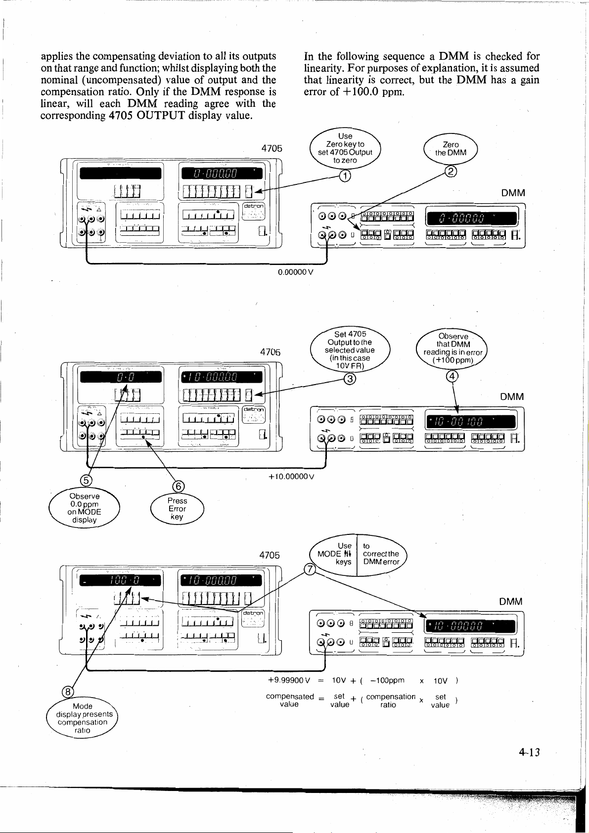
applies the compensating deviation to all its outputs
on that range and function; whilst displaying both the
of
nominal ( uncompensated) value
compensation ratio. Only if the
linear, will each
corresponding 4705
DMM
reading agree with the
OUTPUT
output and the
DMM
response is
display value.
In
the following sequence a D
linearity.
For
purposes
of
explanation, it is assumed
that linearity is correct, but the
error
of
+ 100 .0 ppm.
MM
DMM
is
checked for
has a gain
r (
~
17 17
u·u
1
ti,9
0·00000
+/O·ODDOO
'
4705
'
o.ooooov
r--,'.---,
0 0 0 B
-t--
0 0
.. _ __J
___J
,--
----..
IEJEJdtldBEi[j
>---
~
'---
-----<
[Ej~
___J
1gggggg
\,_
+ I ,-, ,-, ,-, I n
1gggggg
\,_
,-,
,_,
. u u
I I_/ ' I_/
,-,
;-,
,-,
'-'
1m;o,ggg
__J
'--
/_I
I
I_/
1ggggg
__J
'---
,-,
/_/
/_/
,_,
,-,
,-,
DMM
'
_J
DMM
V
_J
R:
fL
(
I I j
Ul?u?
:~~
+10.00000V
0 0 0 B
ll
+9.99900V
compensated = set + ( compensation x set
value value
IEJEJdtiEiBBH
>---
0 u
~[El~-
10V + (
-100ppm
rat10
-----<
x 10V
+ I
,-, ,-, ,-,
i-{
/ u . u u
'-'
1gggggg
value
DMM
,-,
,-,
'
/_/ /_/
1ggggg
R
4-13
Page 42

The 4 705 output has now
gain error of the
will be compensated in the same ratio on this range ·
and function until either the ratio
mode
is
deselected. The Mode display presents the
compensation ratio directly. Note that the
compensation polarity
polarity, therefore the true output
displayed values; in this case + 10 .00000V lO0ppm = +9.99900V.
The linearity
directly comparing its reading with the O UTPUT
display settings.
e.g. at
Other linearity check values could be:
Nominal
+5V
read
voltages are
Check
Point
DMM.
of
the
on this range, both 4705 and
+5.00000V
+4.99500V
4705 set
Value
b_een
compensated for the
All selected output values
is
changed or Error
is
shown, not the error
is
the sum of both
DMM
may now be checked by
, although the terminal
DMM
Reading
DMM
Terminal
Voltages
'Offset'
Offset key
A device being checked against the 4705 (say a
DMM)
N evertheless, a user may wish to perform other
measurements before removing the offset error. The
4705 "Offset" Mode is used for this purpose.
N.B. The
The value
sum ofthe OUTPUT display value and the
display offset value.
The following example generates an offset .of
-100µ,V
values ( unless the 4 705 would be driven
scale
Mode
(DC Functions only)
may have an inherent zero offset error.
MODE
action:
increment or decrement continuously until the
key
).
If
is
· released.
of
output at the 4 705 terminals
on the lOV range
a key
•
It
keys have an automatic
is
held pressed, the display will
is
now the
MODE
of a DMM,
for all set
off-
L
I .
I
r
-0.5V
+0.1 V +0.
+0.0lV
Full Scale Limiting. The OUTPUT display cannot
be raised to a value which sets its overrange digit to
greater than
cannotbe
N evertheless, a combination
value and gain error could result in an off-scale
value.. The 4 705 prevents this by rejecting any
demand for an error-corrected Output Voltage in
excess
message on the
the OUTPUT display.
· Deselection of Error
display, tums the green Error
restores the 4705 gain factor to unity. Normally the
mode
it
is
RANGE.
-0.50000V
lO000V
+0.0lO00V
1,
raised above
of
full scale. The user
MODE
is
deselected by repressing the Error key, but
also tumed off by changing FUNCTION or
-0.50000V
+0.
lO000V
+0.0lO00V
and the Error
+9.9999%
of
is
informed by Error 5
display with no change to
Mode
clears the
-0.49995V
+0.09999V
+0.00999V
MODE
(+999.9
O UTPUT display
LED
display
ppm).
MODE
OFF
and
Connect the
range, ensuring that 4 705 Error and Offset
are UNLIT.
Note that the negative polarity
shown on the
Output voltage
OUTPUT
displayed, not the polarity
error.
DMM
display, i.e. the 4705 offset polarity
to the 4705, both set to
of
the Offset value
MODE
is
more negative than the value on the
display indicates that the
of
the
DMM
l0V
LEDs
is
offset
~
4-14
~
l I
u.
l
u
Page 43

-
_,--
:-._------·---·,-
-_-,:;-·~----_
---
. -
D ·00000 ·
-0·00010
D ·00000 '
0·00000 '
o.ooooov
,--.'.-----..
0 0 0 B
~
.···
· · 0 u
,•a__J
+ D ·000
;---
1€JEIEIEle'e'EIEJ
>---
~!i§~
'---
----------._
-----<
___,/
D
·OOCWO
IQQgQQQ
'----
__J
DMM
!O
·
DMM
'
IQQQQQ
\__
R.
__j
Now the
DMM
gain error only 1?ay be measured:
-0·00010 '
-0.00010 V
Cancels DMM offset .
DMM Offset still cancelled
+9.99990V
=
10.00000
A A
OUTPUT OUTPUT
value = display setting
+ I
,-,
,-,
,-,
I
/_/ • I_/
I_/
+ (-0.00010V )
V
DMM
,-,
,-,
,-,
V
/_I
I_/
I_/
A
MODE display
Offset value
4-15
Page 44

Full Scale Limiting.
combination
result in
e.g
if
offset, the
-20.0000SV
4705
display as a signal
output
The
OUTPUT display
greater
cannot
for the Range in use.
i.e. lOOµV
Deselection of Offset
display,
the
4705
deselected
tumed
Combining Offset and Error modes
(DC
Functions ·only)
By
combining Offset
to
carry
instrument's linearity ( e.g. for a
converter) without the
and
gain errors.
This
is done
the
4705
then using Error Mode
DMM's
present.
In
this condition,
readings from the
represent non-linearities which would still
if
the D
errors.
This
facility also permits a
response
formy=mx+c.
in which y = instrument reading
of
set
an
off-scale output.
-19.99995V
user
is requesting
and
causes Error 5
its previous ( valid) value.
than
Full
be
set
to
a value
and
Other
Ranges:
tums
the
offset
by
repressing the Offset key,
off
by
changing
out
a rapid analysis
by
output
gain
error
MM
were corrected for offset
of
the instrument to its input values in the
x = input value
m = gain ratio
c = zero offset value
The
4705
value
and
zero
is
set
together with
the
combination is invalid.
to
appear
to
the user,
cannot
Scale.
using Offset Mode
The
Offset
greater
lmV
Ranges:
<2%
of
Mode
red
Offset
to
zero.
and
for the
with the offset compensation still
any
4705
LED
Normally
FUNCTION
Error
need
to
DMM's
to
residual deviations in
OUTPUT display settings
user
will reject
offset which would
an
offscale
on
and
continues
be
set
MODE
than
the Offset
<200µV
Full
Range
clears the
O
FF
the
or
modes it is possible
of
a measuring
DMM
correct
compensate
its zero offset
to
zero offset,
to
quantify the linear
any
-100µ,V
output
The
the
MODE
to
a value
display
span
value
MODE
and
reduces
mode
hut
it
is also
RANGE.
or
A-D
compensate
and
for the
DMM
be
present
and
gain
of
to
is
e.g. for a
if y =
then the
Combination
1. U se Offset-mode
2.
3.
either:
= 1 -
~
or:
=
[
4.
Deselect
NOTE:
Test Key
DMM
9.99995x -0.00008,
DMM
+ 5
+80
These
directly from the
the following procedure.
error
val_ue
With
Error
gain
error
value
page 4 - 13. ·
Use
setting
under
response,
of
the
transfe:i; function is:
Instrument
µ (in
---
1Q6
µ(in%)]
1-
---
For
procedure
Therefore the
inhibit
i.e. Offset
on
its 1
needs a gain compensation
ppm
and a zero
V.
compensation
procedure
and
record the
at
operation
Offset
suitable values
LED
mode
to
compensate
and
record the 4705
(ppm
or
to
check
test.
If
the
then
its readings will agree with those
4705
OUTPUT
ppm)]
100
in reverse sequence.
x Input value - y = y =
xlnputvalue-y=y=mx+c
these equations
must
any
deselected
and
the
secondary
OV
range:
offset
compensation
figures
4705
MODE
(See
Note
to
compensate
4705
6 -
(y)
still lit, press Error key.
%)
at
operation
of
the
linearity
instrument
display
reading
follow the above sequence.
4705
has
other
sequence.
mode
cannot
when
Offset key operates in its
function
can
display, <luring
below)
for input offset
MODE
on
page 4 - 13.
for
the
instrument' s
MODE
8 -
OUTPUT
of
the instrument
has
perfect linear
and
to
be valid, the
been
be selected
the
Error
of
'%'.
be
display
displ_ay
(µ)
display
its linear
mx
designed to
LED
read
Use
·
+ c
is lit,
of
of
on
or
r·
l
.-,
[
[
n!
l,
[,]
[]
[1
(
[
[
' [
[
[
4-16
Tests available
There
any
are two stages
Safety
'Test'
and
Memory
sequence.
of
'Test'
checks,
mode.
cannot
The
first stage,
be
omitted from
. ~li -
JI
Page 45

--------=:============
. ·-...
-----:-:-
.....
,.-··=·-=···=··--=--=·-=-=-·=···-=--=··=·····=··=--·-=.c.c·-=····~·-=-·=-·cc=-=cc··-~---cc=·-=c.=·~--··~
...
;;::.~-·-~-~-·-~-~
...
-~-~--~---~·._c.:.c:
...
~.-
~-
~-=··-~-----;;;
..
~
Il!
lll
lll
111
Il
Safety and
On
first pressing the Test key, the 4705 carries out
Memory
Checks
three checks:
1.
Operation
of
the Safety trip, buzzer and reset
circuitry.
2. Calibration Memory integrity.
3. Over-voltage check. (High voltage when not in
HV
state).
Mess,ages appear on the
completion is signalled by the
MODE
Test
LED
display, and
going OFF.
The second stage Display and Key checks may be
omitted by pressing any key
Display and Key Checks
If
the Test
Key
is re-pressed before pressing any
o~her
than Test.
other key, a visual sequence tests the front panel:
1.
Gas
discharge displays. .
2. Key
3.
LEDs.
Key contacts (user-selected).
4. Reset Check
The program ensures that user tests the Reset
action.
Press
Reset Key:
SAFEtY message is replaced by the running
The
message and the buzzer stops sounding. Relay
operation can be heard
<luring
the automatic checks
which follow.
5. Calibration
This
isa
Memory
sum-~heck
Check
ofthe
Non-volatile RAM.
Ifthe
check fails, the Message F AIL 6 appears, otherwise
no message.
6. Over-Voltage Checks
The 4 705 automatically tests
,the
over-voltage
detector threshold levels in Low Voltage state.
If
the check fails, the message Fait 2 appears,
otherwise
PASS message indicates both tests
completed successfully.
7. The Test
LED
goes OFF.
The 4 705 remains in the key-contact mode until the
Zero Key is pressed
deselected.
It
may then
or
test
is
be used normally.
N.B.
1.
At
ariy time
Test
sequence may be aborted by pressing
<luring
the second stage, the
Test Key again.
2. During self-test the instrument reset
is
facility
Test Sequence
The
Front
or
<luring
Safety and
1. Initial Conditions
Test
sequence.
Memory
Ensure that OUTPUT
Spec
LEDs
not available.
Rear
panel terminals are' not energized
Checks
OFF
LED
is lit, Error and
are unlit. Check that Test
LED
unlit.
2. Press Test
Test
LED
Key:
lights as the checks begin.
is
The following table summarizes the
MODE
messages: ·
Message
SAFEtY rumiing
PASS
FAIL
6 only
Reason
First
stage
of
'test' operative.
N o failure disco
ve
red.
Parity error in Calibration
Memory check.
FAIL
2 only
High voltage can be present in
Low Voltage state.
Any
combin~tion.
can appear m sequence, replacing the
of
these two F AIL messages
running
message.
8.
To
terminate Test before the
checks, press any key
other than Test:
Display
and Key
4705 returns to prior conditions.
display
3. Safety Trip Check
The 4 705 tests the safety trip circuits.
message appears on the
MODE
The
SAFEtY
display and the
buzzer will sound continuously when the trips have
operated, and the
Reset
LED
flashes.
. 4-17
Page 46
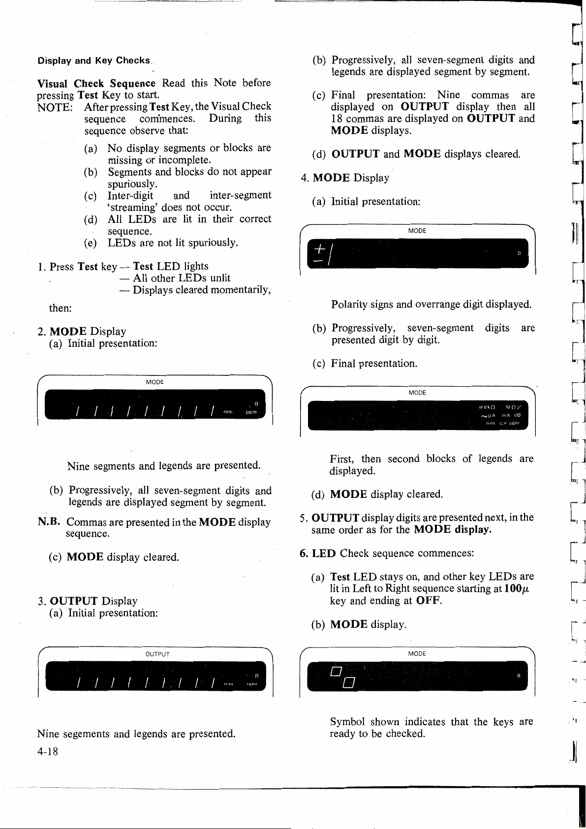
[
Display and Key Checks.
Visual Check Sequence Read this Note before
pressing Test Key to start.
NOTE:
1.
Press Test key - Test
then:
2.
MODE Display
(a) Initial presentation:
After pressing Test Key, the Visual Check
sequence cominences. During this
sequence observe that:
( a)
No
display segments or blocks are
missing
(b) Segments and blocks do not appear
spuriously.
( c) Inter-digit and inter-segment
'streaming' does not occur.
( d) All
sequence.
( e)
LEDs
or
incomplete.
LEDs
- All other
- Displays cleared momentarily,
are lit in their correct
are
not
lit spuriously.
LED
lights
LEDs
unlit
(b) Progressively, all seven-segment digits and
legends are displayed segment by segment.
( c) Final presentation: Nine commas are
displayed on
18 commas are displayed on
MODE displays.
OUTPUT and
(d)
MODE
4.
( a) Initial presentation:
Display
OUTPUT display then all
OUTPUT and
MODE
MODE
displays cleared.
+ I . 8
Polarity signs and overrange digit displayed.
(b) Progressively, seven-segment digits are
presented digit by digit.
( c) Final presentation.
[
r
..
,
[
[
lll
[
[
[
MODE
,,,
B
ppm
n
"'""
I I I I I I I I I
r
Nine segments and legends are presented.
(b) Progressively, all seven-segment digits and
legends are displayed segment by segment.
N.B. Commas are presented in the MODE display
sequence.
(c)
MODE display cleared.
3.
0 UTPUT Display
( a) Initial presentation:
OUTPUT
1
I I I I I I _ I I I
rem
,.
MODE
mVkO
...._.pA rnA
n•m
l
.il
First, then second blocks
displayed.
( d)
MODE display cleared.
5.
OUTPUT display digits are presented next, in the
same order as for the
6. LED Check sequence commences:
LED
(a) Test
lit in Left to Right sequence starting at
key and ending at O FF.
(b) MODE display.
stays on, and other key
MODE
MODE
of
legends are
display.
LEDs
100 µ
0 '
0 8
MO/
ppn1
C
clG
C
C
C
[
are
_[
. ''l
Nine segements and legends are presented.
4-18
Symbol shown indicates that the keys are
ready to be checked.
JI
I
Page 47
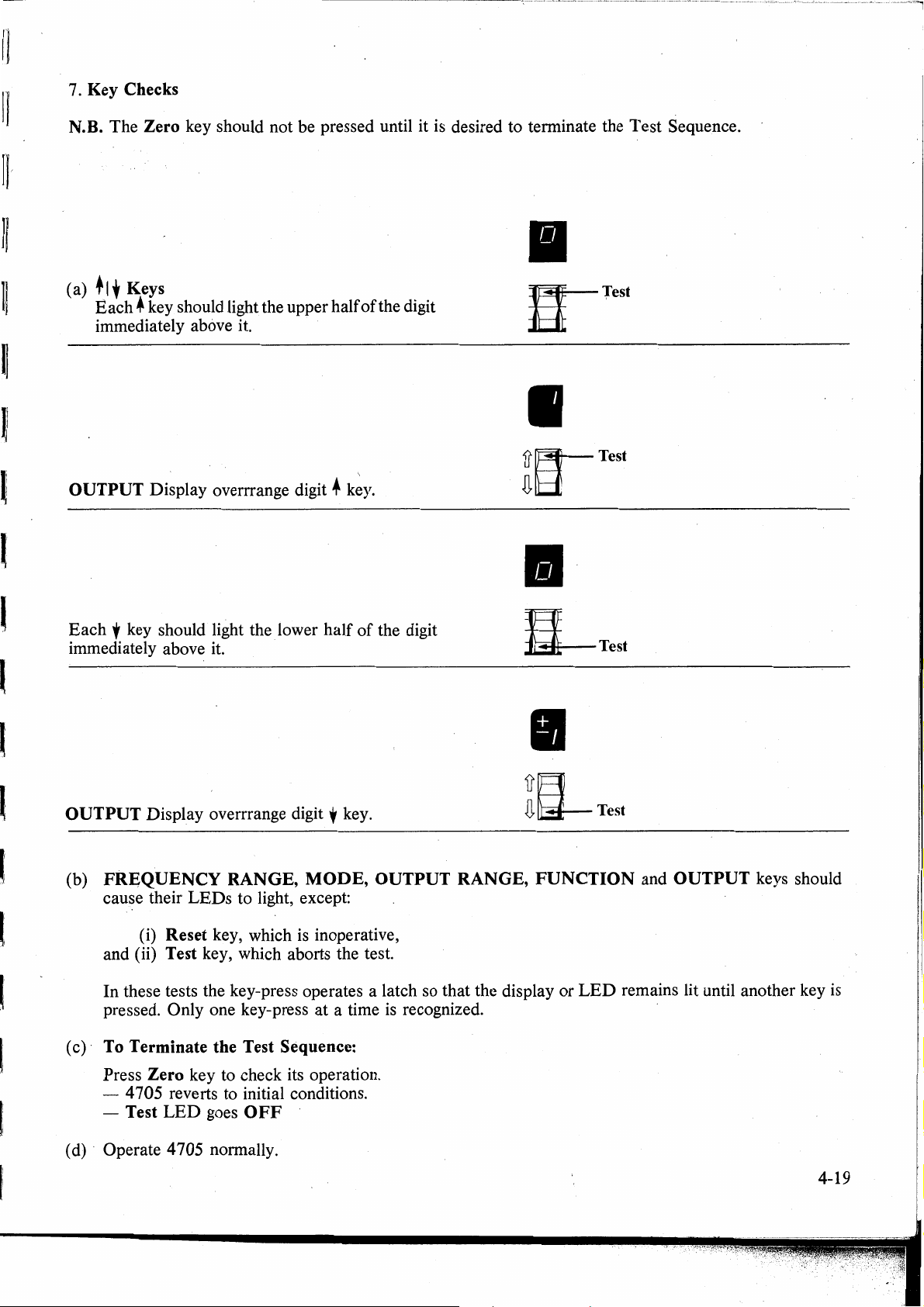
-------------,----------~~~-~---'-'·-·---·-------·.
11
7. Key Checks
-------~----···--------·-------------·---
--
----'-~-
---
------
·---·--·------·--·---
------·
--
Il
11
~
N.B. The Zero key should not be pressed until it
(a)
+1
t Keys
Bach*
immediately above
OUTPUT Display overrrange digit +
key should light the upper half
it.
k~y.
of
the digit
is
desired to terminate the Test Sequence.
Il
n-Test
Il
(
l
l
Il
Each f key should light the lower half
immediately above it.
OUTPUT Display overrrange digit
(b) FREQUENCY RANGE, MODE, OUTPUT RANGE, FUNCTION and OUTPUT keys should
cause their
(i) Reset key, which
and
(ii) Test key, which aborts the test.
In these tests the key-press operates a latch so that the display or
pressed. Only one key-press at a time
LEDs
to light, except:
is
of
the digit
y key.
inoperative,
is
recognized.
Et.-Test
IJ
ia-Test
LED
remains lit until another key
is
(c) · To Terminate the Test Sequence:
Press Zero key to check its operation.
- 4705 reverts to initial conditions.
- Test
(d) · Operate 4705 normally.
LED
goes
OFF
4-19
Page 48

Warnings
High Pitph Audible Warning
and
Massages
(a) Sounds at approx 5 pulses per second
the High Voltage being connected to the terminals, when the OUTPUT TERMINAL VOLTAGE
DC
WILL EXCEED 110V
(b) Sounds at approx 1 second intervals with OUTPUT
(c) Sounds for 1 second with blank FREQUENCY display when frequency auto-ranges up or down.
(d) Sounds continuously when SAFEtY message
Low Pitch Audible Warning
(a) _ Sounds when any message
messages).
(b) Sounds when any invalid bus command
FREQUENCY/MODE
Error 1 Spec
:[+Lim,
Calibrate Mode
Error 3
Error 4
Error
Error 6
Error 7
Error 8
Error 9
Error
Error OL - Voltage Ranges
FAIL 1
FAIL2
FAIL3
FAIL4
FAIL5
FAIL6
5
EF
Calibrate Mode
Calibrate Mode
Offset or
Error Mode
Calibrate Mode
(Resistance)
100V and
1000V Ranges
Selection error
Option not fitted
Externa! frequency -
- Current Ranges
- Excessive interna! temperature. F AIL 7 - 400V power supply fault - this 'trip' may
- Over-voltage reset itself if no hardware fault exists
-Control
- Precision divider fault. F AIL 8 - 3 8V power supply fault.
- Safety circuits tripped. FAIL 9 - 15V in-guard power supply fault.
- Calibration memory sumcheck
non-parity.
display
Mode:[%]
-Lim]
data corrupted. and the Fail message
or 75V RMS.
is
<luring
displayed on the
Tolerance exceeds 100%.
The selected limit
OUTPUT OFF. Error 2
Incorrect FUNCTION, OUTPUT or FREQUENCY
RANGE for this calibration mode.
Correction out
Temporary message. The selected deviation would exceed
the full-scale value. Activation has been prevented.
The resistance value selected exceeds the calibration
value.
Temporary message. The selected Voltage and Frequency
exceeds the 4 705 interna! constraints. Activation has
been prevented.
Temporary message. The operation requested by the user is not
possible
Temporary message. The requested range or function option is not
fitted.
The externa! frequency is not present, machine will
perform out of specification.
The output has been current-Iimited by an overload.
(If
in
switched OFF).
The terminal voltage has been compliance-limited to 3V.
(Load impedance too high)
the 3 second delay between selection
ON
in High Voltage State.
is
present on
MODE/FREQUENCY
is.
received.
is
of
limits.
.in
present machine configuration.
l00V
or 1000V range, OUTPUT
MODE
off-scale.
display
ofOUTPUT
<luring
displ~y (except recalled
is
automatically
self test.
is
temporary.
ON
and
SAFEtY - Test Mode
running - Test Mode - Indicates test in progress.
PASS
Recalled Messages
ISS
Addr
4-20
-Test
XX.XX
XX
Mode
- Firmware issue· number (selected by pressing Error then
-
IEEE
-Safety
-FAIL
and FAIL 2
488 Bus address
circuits tested by tripping: Press Reset key to continue test.
6 did not occur
<lid
not occur
as
set
on
<luring
<luring
Address switch (selected by pressing Error then +Lim).
test of calibration memory parity,
test of over-voltage thresholds.
-Lim).
[I]
Page 49

]I
JI
]I
]I
----·-~----·--···-·------------·---------------------·-·------------------------------------------11
Processor 'Busy' (Keyboard Unreceptive)
4705 will not respond to commands while legend 'B'
The
except t0 override
KEY LEDs
Basic Indications:
Lit - The labelled facility
Unlit - The labelled facility
Lit Green (Spec and Error
Lit Green (Store only)
<luring
safety delay.
only)-Other
printed ABOVE their keys, as directed by the arrows
-FREQUENCY
memory stores.
MODE
keys' facilities are reassigned to the secondary modes
RANGE keys are reassigned to select
is
present on the
is
selected and active.
is
not selected.
MODE
and OUTPUT displays
Fl-FS
JI
11
ll
li
ll
ll
ll
ll
·Warnings with Function
OUTPUT RANGE 100V or 1000V
- A voltage in excess
ON
LED
flashing while in Low Voltage State with
-An
~
attempt to select output in excess of 1 I0V
Repressing OUTPUT ON key will switch the
DC
or AC Selected:
of
HOV
DC
LED
flashing
or 75V RMS has been selected (OUTPUT
OUTPUT
DC
or 75V RMS has been prevented.
HIGH
ON
VOLTAGE ON.
ON
or OFF).
l!
lf
li
lf
. 4-21
Page 50

DANGIR
,..
'
THIS·
...
.
HIGH
INSTRUMENT
OF DELIVERING
A
llTHAl
VOLTAGE
IS -CAPABLE
lllCTRIC
SHOCK
!
m
L-:
__
-
__
-,
___
·,·,_,_
.•
=·11
r:
'
d_71
;·-
JlJ
~
,..
...
Unless
it is safe
DO
I+
I-
and terminals
It
your
you
NOT
Hi
Guard terminal is
sensitive
voltage
can
instrument!
are sure
damage
to
do so,
TOUCH
or
Lo leads.
to
over -
that
the
4-22
DANGIR
Page 51

l
]
]
l
l
l
l
l
l
l
l
S·ECTION 5
SYSTEMS
THE IEEE
APPLICATION
488
INTERFACE ·
VIA
I ntroduction bus-connected devices under the direction or a
system controller.
Section 5 gives the information necessary to put the
4705 into operation on the
will
operators
pitched at an introductory leve
information, refer to the standard specification,
which appears in the publication
Std. 488-1978.
Section Contents
The section
information together. These divisions are:
lnterface Capability - the permitted options
which have been implemented in the 4705.
Typical System - a briefview
using the 4705 to
Using the 4705
operation.
Programming I nstructions - how the 4 705
facilities have been transferred into remote
commands.
Programming of Operational Functions - more
detail about the codes which control 4 705
operation.
Programming of
program the 4 705 to obtain specific types of
readout.
be first-time users ofthe bus, the text
is
divided so as to group certain types of
checka
in
a System - implications ofbus
Bus
IEEE
DMM
Transmissions - how to
488 bus. As some
1.
For
more detailed
ANSI/IEEE
of
a typical process
calibration.
is
Programming Options
The instrument can be programmed via the
Interface,
( 1) Change its operational state (Range, Function,
(2) Transmit its own status data to other devices on
( 3) Request service from the system controller.
Capability Codes
To conform to the standard specification, it
essential for a compatible device to encompass the
full
The
of the standard bus features, so that manufacturers
can provide brief coded descriptions of their own
interfaces' overall capability. A code string
printed on the product itself.
The codes which apply to the 4 705 are given in
Table 5.1, together with short descriptions. They
also appear on the rear of the instrument next to the
interface connector.
Appendix C
fuller description of each code.
Code Interface Function
to:
Frequency, Mode, Output, etc).
the bus.
range of bus capabilities.
IEEE
488 document describes and codes each
ofthe
IEEE
488 document contains a
IEEE
is
is
often
not
Service Request - why the 4 705 needs the
controller' s attention and how it gets
Activation of Commands - what the 4 705 does
with the commands it receives.
Operational Sequence Guidelines a little
general · help with programming sequences.
INTERFACE
IE~E Standard
The 4 705 conforms to the Standard specification
IEEE
Interf ace for Programmable . Instrumentation'.
It can be connected to the
and set into programmed communication with other
4888-1978 -
CAPABILITY
488
'IEEE
IEEE
it.
Standard Digital
488 Interface Bus
SHl
AHl
T6
TE~
L4
LE~
SRl
RL2
pp~
DCl
DT~
o/,
El
Table
Source Handshake Capability
Acceptor Handshake Capability
Talker (basic talker, serial poll, unaddressed to
talk if addressed to listen)
No Address Extension Talker Mode
Listener (basic listener, unaddressed to listen if
addressed to talk)
No Address Extension Listener Mode
Service Request Capability
Remote/Local
Lockout)
No Parallel Poll Capability
Device Clear Capability
No Device Trigger Capability
No Controller Capability
Open-Collector Drivers
5.1
IEEE lnterface Capability.
Capability (without Local
5-1
Page 52

Bus Addresses
When an
IEEE
488 system comprises several
instruments, a unique 'Address' should be assigned
to each to enable the controller to communicate with
them individually.
One address
is
sufficient for a Datron instrument, as
the controller can add information to it to define
or
either 'talk'
'listen'.
I nterconnections
Instruments fitted with an
normally communicate through a set
interconnecting cables, specified in the
IEEE
488 interface
of
IEEE
488-
1978 Standard document.
The 4705's interface connector, J27, is fitted on its
rear panel.
It
receives the specified connector, whose
pin designations are also standardized and.shown in
Fig. 5.1 and Table 5.2.
Fig.
5.1
J27 Pin Layout
12
24
13
J27
PinNo
1
2
3
4
·5
6
7
8
9
10
11
12
13
14
15
16
17
18
19
20
21
22
23
24
Name Description
Data
Input
DIOl
DIO2
DIO3
DIO4
EOI
DAV
NRFD
NDAC
IFC
SRQ
ATN
SHIELD
DIO5
DIO6
DIO7
DIO8
REN
GND6
GND7
GND8
GND9
GNDlO
GNO
11
-GNO
Table 5.2
Data
Data
Data
End
Data
Not
ready for
Not
Interface Clear
Service Request
Attention
Screening
Safety
Data
Data
Data
Data
Remote
Gnd
Gnd
Gnd
Gnd
Gnd
Gnd
4 705 Logic
connected
IEEE
Output
Input
Output
Input
Output
Input
Output
or
Identify
Valid
Data
Data
Accepted
on
cable ( connected
Ground)
Input
Output
Input
Output
Input
Output
Input
Output
Enab]e
wire
of
twisted pair with DAV
wire
of
twisted
wire
of
twisted pair with
wire.
of
twisted pair with
wire
of
twisted pair with
wire
of
twisted pair with
Ground
to
4 705 Safety Ground)
488-1978 -Connector
- Pin Designations
Line 1
Line 2
Line 3
Line 4
Line 5
Line 6
Line 7
Line 8
pair
with
(lnternally
to
NRFD
NDAC
IFC
SRQ
ATN
5-2
Controller
Controls, Talks
and Listens
<
~
D
Datron4705
Talks
and
Listens
-
Fig
5.2. Typical System
DIO1
DIO2
. DIO3
Data DIO4
lnput-Output
D
Hi
Hi
Lo
Lo
DMM
Talks arid Listens
lJ
Printer
Listens
End
or ldentify
Inte
rface Clear
vice·Request
Ser
Att
ention
Re
mote Enable
Dat
a Valid
Not
Ready for Data
Not
Data Accepted NDAC (Handshake)
010 5
DIO6
DIO7
DIO8
IFC
EOI }
SRQ
ATN
REN
DAV
NRFD
5
. lnterface
Management
Lines
} 3 Transfer
Control Lines
Il,
Page 53

]]
]ij
]]
]]
])
Typical System
A typical system
directect' by a controlling device able to:
(a)
(b)
and ( c)
EXAMPLE
In
the system example (Fig. 5.2) the
programme task could be to check the
calibration against the
results.
events:
( 1)
output
commands must not be received
printer and so the controller sends the general bus
message
messages, the controller makes all bus devices
interpret any D1O-line
flow commands,
The
The
controller needs to instruct the 4 705 to setJts
toa
'Unlisten'.
is
shown in Fig. 5 .2.
'Control' (lssue commands)
'Listen' (Receive data)
'Talk' (Transmit data)
OF
A SYSTEM IN OPERATION
4705,
following is a typical sequence
calibration point for the
When
data
as configuration
by
holding the ATN line true.
The
and print
DMM.
by
the
DMM
sending general
system is
DMM
out
the
of
These
or
the
or
data-
(6)As
(Wired-OR function), the controller needs to
discover which one sent the
all devices one by one
the
ON.
(7)
sends the
via the D1O lines to initiate the reading. After a short
delay for measuremeni, the
data
transfer.
( 8) The controller identifies the D
poll. Finding that the reading is available, it sends
the
address, to activate both devices.
· (9)
releasing both devices to start the transfer.
DMM
to the printer. This
to the printer, and
byte is transferred
Transfer-Control lines.
the
SRQ
facility
4700
is the
SRQ
It
next addresses the
GET message
and
SRQ'
s the controller when it is ready for
DMM's
The
sends its data, byte
talk address, and printer's listen
controller sets the A TN line false, thus
is
available to all bus devices
'SRQ'.
('serial poll'), finds out that
source and that its
DMM
(Group
DMM
by
data
must be in a form acceptable
to
ensure orderly transfer, each
by
'Handshake', using the three
It
therefore asks
OUTPUT
as a listener, and
Execute Trigger)
prepares output
MM
byte, via the D1O lines
by
a serial
The
is
The
(2)
address to force it to receive, followed
4 705 configuration commands ( including the
Output Disable message, to prevent the
receiving an inappropriate analog input). The
instructions are passed along the
output) lines as coded messages (bytes).
used is
lnterchange ).
(3) Although the 4705 accepts the instructions as
they are passed, their implementation takes a short
time. The controller would perform other tasks
<luring
configuring commands to the D
and the
( 4)
operation, so the controller performs other tasks
while waiting, such as configuring the printer.
(5)
addresses the 4705 as listener, and re-configures its
Analog Output
the 4 705 has executed its previous instructions, it
sets·
OUTPUT
executed.
message back to the controller via the
Request) management line, if programmed to do
so.
controller then sends the
ASCII (American Std. Code for Information
this period.
DMM
The
D
MM
The
controller next generates 'Unlisten',
OUTPUT
In
is
In
the example, it would pass
MM,
listen address have been sent.
also needs time to settle into stab le
On
by
an Output Enable message.
ON
immediately, otherwise the
set
ON
as soon as they have been
either case,the instrument sends a
4705's
D10
after
SRQ
(
data
The
'U
(Service
listen
by
DMM
input-
code
nlisten'
If
( 10) U sually the controller is also listening to this
data
transfer to determine when it
aid to the controller and printer, the
another message with the last byte to be transferred
(EOI-end
management line ).
The
( 11)
can start again
The
controller holds the
remote control.
GTL,
· permit temporary manual control
IFC
line is used
clear any activity off the bus.
Sequences such as this are often assembled into
programs
points; changing functions, ranges and output levels
as designed by the user. The program would also
include 'display' messages to complete the printout
in a recognizable form for, the user' s convenience.
Programs must also cater for F
or identify, using another bus
sequence is complete, and the controller
at
another calibration point.
REN
It
can send an addressed command
or
some controllers can set
at
the discretion
to
check
DMMs
is
complete.
D
MM
line true when taking
REN
of
a device. The
ofthe
controller, to
at
many calibration
AIL
and
As
can send
false, to
ERROR
SRQs.
With a
cause the
within specification, using its 'calibrate' mode. ·
Datron
DMM
Autocal
DMM,
errors to be reduced until they are
other sequences can
an
·
.
5-3
Page 54

Using the
4705
in a System
ADDRESSING THE 4705
Bus Address
The instrument address
way miniature switch near the interface connector on
the rear panel. Five
any address
in
the range
code.
e.g. Switch setting -
5 4 3 2 1
is
set manually using a six-
of
the switches are used to set
00
to 30, using a binary
ADD
11010 = ADDRESS 26
'O'
'1'
'ADD'
The sixth switch
variants. In the 4705, the position of the
switch
is
immaterial, as the normal bus addresses
is
provided for possible future
ADD
can be selected at either setting.
Addresses
With an address selected in the range O to
0-30
30
the
instrument may be controlled manually, or remotely
as part
of
a system on the Bus. The address selected
must be the same as that used in the controller
program to activate the 4705.
N.B. The selected address can be temporarily
displayed on the front panel when in manual
control, by touching
Error and then
Guard.
AS
A4
A3
A2
Al
0 0 0
0 0 0
0 0 0
0 0 0
0 0 1
0 0 1
0 0 1
0 0 1
0 1 0
0 1 0
0 1 0
0 1 0
0 1 1
0 1 1
0 1 1
0 1 1
1 0 0
1 0 0
1 0 0
1 0 0
1 0 1
1 0 1
1 0 1
1 0 1
1 1 0
1 1 0
1 1 0
1 1 0
1 1 1
1 1 1
1 1 1
Table 5.3 Address Selection
0 0
0 1
1 0
1 1
0 0
0 1
1 0
1 1
0 0
· 0 1
1 0
1 1
0 0
0 1
1 0
1 1
0 0
0 1
1 0
1 1 .
0
O·
0 1
1 0
1 1
0 0
0 1
1 0
1 1
0 0
0 1
1 0
5-4
)-~-
Decimal
Code
00
01
02
t
03
04
05
06
07
08
09
10
11
12
13
14
15
16
17
18
19
20
21
22
23
24
25
26 ( e.g. above)
27
28
29
30
Remote Operation
When the 4 705
the controller, the legend
is
operating under the direction of
rem appears on the mode
display, and all front panel controls are disabled
except
Power and Reset.
On entering remote, any earlier (manual) selection
of
Error mode
operation, the facilities
is
cancelled. During remote
of
Error mode are excluded,
as they can easily be programmed into the controller.
Spec mode
can be obtained by bus command. There is no
mode display on · the front panel
is
also cancelled, but 'Spec' information
<luring
remote
Spec
operation.
is
The 4 705 power-up sequence
performed as for
manual operation. After power-up, and on recovery
from a power failure, the 4705 generates an
SRQ
and prepares an 'RQS Status Byte' for
transmission to the controller as a response to its
subsequent
Calibration Enable
A 'Calibration Enable' command via the bus
serial poll.
is
required to set the instrument into its Remote
Calibration mode (the
CALIBRATION
ENABLE
keyswitch on the rear panel must already be set at
ENABLE). Selection
of
any address 0-30 inhibits
manual calibration from the front panel.
Address
31
(Illegal bus address)
This address configures manual operation only,
inhibiting remote facilities. Address
selected (with
CAL
key set to ENABLE), for
31
must be
manual calibration to be carried out.
Temporary Transfer to Local Operation (GTL)
The 4705 can be programmed to switch into 'Local'
operation (Command GTL), permitting a user to
take manual control from the front panel. The system
controller regains
'Remote' control by sending the
Page 55
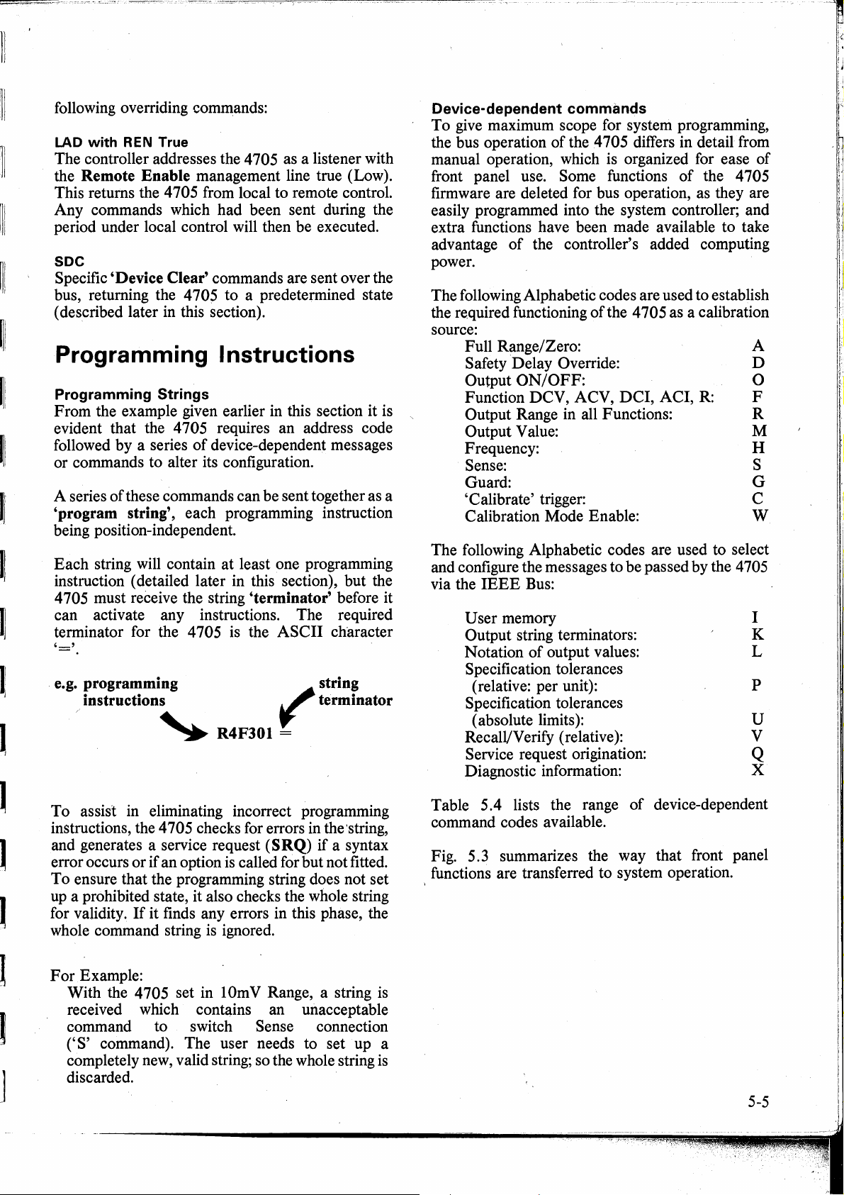
11
11
lli
I!
~
)!
1
. e.g. programming
following overriding commands:
LAD
with
REN
True
The controller addresses the 4705 as a listener with
Remote Enable management line true (Low).
the
This retums the 4705 from local to remote control.
Any commands which had been sent
period under local control will then be executed.
SDC
Specific 'Device Clear' commands are sent over the
bus, retuming the 4705 to a predetermined state
( des.cribed later in this section).
<luring
the
Programming lnstructions
Programming Strings
From the example given earlier in this section it is ,
evident that the 4 705 requires an address code
of
followed by a series
or commands to alter its configuration.
of
A series
'program string', each programming instruction
being position-independent.
Each string will contain at least one programming
instruction ( detailed later in this section), but the
4 705 must receive the string
can activate any instructions. The required
terminator for the 4 705
'='
these commands can be sent together as a
instructions
~
device-dependent messages
'terminator' before it
is
the ASCII character
string
~
terminator
R4F301 =
Device-dependent commands
To
give
maximum scope for system programming,
the bus operation of the 4705 differs in detail from
manual operation, which is organized for ease
front panel use. Some functions of the 4705
firmware are deleted for bus operation, as they are
easily programmed into the system controller; and
extra functions have been made available to take
of
advantage
power.
The following Alphabetic codes are used to establish
the required functioning
source:
Full Range/Zero: A
Safety Delay Override: D
Output
Function DCV, ACV,
Output Range in all Functions:
Output Value: M
Frequency: H
Sense: S
Guard: G
'Calibrate' trigger: C
Calibration Mode Enable: W
The following Alphabetic codes are used to select
and configure the messages to be passed by the 4705
via the
IEEE
User memory
Output string terminators:
Notation
Specification tolerances
(relative: per unit):
Specification tolerances
( absolute limits
Recall/Verify (relative):
Service request origination:
Diagnostic information:
the controller' s added computing
of
the 4 705 as a calibration
ON/OFF:
DCI,
ACI,
R:
Bus:
of
output values:
):
of
0
F
R
I
K
L
p
u
V
Q
X
J
To assist in eliminating incorrect programming
instructions, the 4705 checks for errors in the·string,
and generates a service request
if
error occurs or
To ensure that the programming string does not set
up a prohibited state, it also checks the whole string
for validity.
whole command string
For
Example:
With the 4705 set in lOmV Range, a string
received which contains an unacceptable
command to switch Sense connection
('S'
command). The user needs to set up a
completely new, valid string; so the whole string
discarded.
an option
If
it finds any errors in this phase, the
is
(SRQ)
is
called for but not fitted.
ignored.
if
a syntax
is
is
Table 5.4 lists the range
command codes available.
Fig.
5.
3 summarizes the way that front panel
functions are transferred to system operation.
of
device-dependent
5-5
Page 56

CONTROL
Full Range/Zero
Calibration Mod~
Safety Delay
Function
Guard
Frequency
Memory
(users Aide-Memoire)
Output String
Terminators
Value Notation
(Output to bus)
Main RegisterValue
Output
Specification T olerance
Service Request
Output Range
Sense
Specification Tolerance
(Absolute Limits
Uncertainty)
RecallNerify
Calibration
Diagnostic
(The calstore values
r.elate
set at the lime)
Refer to Calibration
and Servicing Handbook for description
correct process.
Table
of
to the function
5.4
4705
of
CODE
AO
+ FullRange ) li.e.notifROset)
A1
- FullRange )
A2
"CAL" (Calibration Trigger)
co
"SET"
C1
"STO"
C2
"±O"(inDC)
C3
"Precal" (in AC)
DC Coarse Gain
C4
DCLinearity
C5
Safety delay Active
00
Safety delay Over-Ridden
01
V (DC Voltage)
FO
F1
VA (DC Current)
F2
A-
F3
R (Resistance)
F4
LocalGuard
GO
Remote Guard
G1
Numeric value of frequency
H''''
Store next 16 ASCII characters
I
Crfollowed by Lf with EOI
KO
Crfollowed by Lf
K1
Crwith:EOI
K2
Cr
K3
LfwithEOI
K4
'Lf
K5
EOI with last character
K6
No terminator
K7
· Scientific with lengends
LO
Scientific with no legends
L1
Engineering with legends
L2
Engineering with no legends
L3
M±'"
Numericvalueof'Output' display
00
Output
01
OutputON
PO
24hours
P1
90days
P2 1 year
00
SRO on all specified states
01
SRO on Overload and Fail only
02
NoSROs
Autorange
RO
100µ
R1
1m
R2
10m
R3
100m
R4
1
R5
10
R6
100
R7
1000
R8
R9
LocalSense
so
Remote Sense
S1
24hours
uo
90days
U1
1 year
U2
24hours
U3
,90days
U4
1 year
U5
'Output' Value
vo
'Frequency Setting'
V1
4705Status
V2
Software Status (Part No/lssue)
V3
F1
V4
F2 )
V5
F3 ) Recall 'Stored' frequency value
V6
F4
V?
F5 )
va
Calibration Mode Disable
wo
Calibration Mode Enable
W1
Zero Cal Store
xo
Gain Cal Store
X1
STO Cal Gain Factor
X2
X3
Zero offset ) Factory
X4
Gain offset ) corrections
Linearity (not AC) )
X5
Reference Divider Setting
X6
NotUsed
X?
User Message Recall
xa
IEEE
DESCRIPTION
Zero ) But not in Autorange
(AC Voltage)
(AC Current)
OFF
10H
100H
1kH
10kH
100kH
1MH
10MH
100MH
)
)
488
Command Codes
888
Sectlon 8
)
) Output low limit to bus
)
)
) Output high limit to bus
)
I
I
I
I
, ,,,,
I .
I
,,,7n;
UUU,UL
i
((~)
OUTPUT RANGE
@aaäaaaä
100
1000
lkO
10k0
100k0
FS
~
Test
1gggg
0 l
AG
FUNCTION OUTPUT
Note: Frequency Range selection
is
not
autoranges to correct range
for
"H"
~
nt Panel Controls to System Operation
1MO 10MO 100MO
1g~gg
DC
Resel
_:
ON . .::....
required. Frequency
value.
= no comparable
OFF
commands
v
"'
Full
Rarige
Zero ,
~
rdatron"
IN.STRUMFNIS
4705 AUTOCAL
MUL TIFUNCTION
"- CALIBRATOR
~
Page 57

CONTROL
Full Range/Zero
Calibration Mode '
Safety Delay
Function
Guard
Frequency.
Memory
(usersAide-Memoire)
Output String
Terminators
Value Notation
(Outputto bus)
Main
Register Value
Output
Specification Tolerance
Service Request
Output Range
Sense
Specification Tolerance
(Absolute Limits of
Uncertainty)
RecallNerify
Calibration
Diagnostic
(The calstore values
r.elate
to the function
atthe
time)
set
Refer
to
Table
Calibration
5.4
4705
ol
and Servicing Handbook for description
correct process.
CODE
AO
+ Full Range ) li.e.
A1
- FullRange )
A2
"CAL "(Calibralion Trigger)
co
C1
"SET"
"STD"
C2
"±0"(inDC)
C3
"Precal" (in AC)
C4
DC Coarse Gain
C5
DCLinearity
Safety delay Active
D0
D1
Safety delay Over-Aidden
F0
V (DC Voltage)
F1
V-
F2
A (DC Current)
A-
F3
F4
R (Resistance)
LocalGuard
G0
Remote
Gt
H
....
Numeric value
Store
I
Cr
KO
Cr
K1
Crwith:EOI
K2
K3
Cr
LlwithEOI
K4
"LI
K5
EOI with last character
K6
K7
No terminator
Scientificwith lengends
LO.
Scientific with
L1
Engineering with legends
L2
Engineering with
L3
M±*'*
Numeric value
OutputOFF
00
OutputON
01
24hours
P0
P1
90days
P2
1 year
SRO
oo
SRO
01
02
NoSROs
RO
Autorange
R1
100/L
1m
A2
10m
A3
100m
A4
1
A5
10
A6
100
R7
1000
AB
A9
so
LocalSense
Remote Sense
St
24hours
uo
90days
Ut
1 year
U2
24hours
U3
,90days
U4
1year
U5
'Output' Value
vo
'Frequency Setting'
V1
V2
4705Status
V3
Soltware Status (Part Noilssue)
F1
V4
F2 )
V5
F3 ) Recall 'Stored" frequency value
V6
V7
F4 )
F5 )
VB
Calibration Mode Disable
wo
Calibration
W1
Zero Cal Store
xo
Gain Cal Store
X1
STD Cal Gain F actor
X2
X3
Zero offset ) Factory
X4
Gain offset ) correclions
Linearity (not AC) )
X5
X6
Reference Divider Setting
X7
NotUsed
X8
User Message Recall
IEEE
DESCRIPTION
Zero ) But
(ACVoltage)
(AC Current)
Guard
of
next
16
ASCII characters
lollowed by
followed
488
LI
by
LI
no
of
on all specified states
on
Overload and Fail only
10n
100n
1kU
10kh
100kU
1MU
10MU
100MU
)
Mode Enable
Command Codes
not
in Autorange
not
if
RO
set)
see
Sectlon8
frequency
with EOI
legends
no
legends
'Output' display
)
) Output low limit
)
)
) Output high limit to bus
)
to
bus
MOOE FREOUENCY
, n n k
I • LI
LI"'
I
I
I
,
nn,-,nn/
I
'UUU,UL
~
I
Full
Rarge
Zero
~
rdarron
INSTHUMFNTS
4705 AUTOCAL
MUL TIFUNCTION
CALIBRATOR
~f-Jl
[±]1
t,
JI
DANGER
HIGH VOL TAGE
~&
!+
I·
Guard
@@@
u
•.............
::.:.;.·
.·
.:::.
:,
...
/::.·
·.::::·::-::
~
FREOUENCY RANGE
~
-
F1
F2 F3
i
((~~~)
OUTPUT RANGE
@Elelåi9:täeleJ
100
1000
lkO
10k0
100k0
!MO
F4
FS-.
10MO 100MO
1~ggg1gg~g
0 I
AG
DC
Rese!
_:
ON
-~
FUNCTION OUTPUT
OFF
r±11
·r·
•.
i
._.
Bus
operation
of
"Spec"
mode
__
)
'·
l.
·-,l-1·111
IT-,11'
Note:
Guard Sense Spec Error
-Remote-
sro
MODE
ser
Frequency
is
autoranges
for
~
Range
not
required.
"H"
value.
- no comparable commands
Frequency
to
correct
selection
range
th
rh
-.
r-Jj
Fig 5.3 Transfer of Front Panel Controls
to
System Operation
.111
'11
. I
: - I
·1r
-
--
;
..,.
5-6
Page 58

DANGIR
HIGH VOLTAGE
FRONT
terminals
Full
THIS
,..
READ THIS: For manual operation, the47O5High Voltage lnterlocks
employ
at the OUTPUT
In
received
text).
In manual
control
protection
danger
WHENEVER THE 4705 IS BEING USED
EXCESS OF 75V, THERE MUST BE NO ACCESS
REAR PANEL OUTPUT TERMINALS .
deliberate
system
of
is
actions
terminals.
applications,
from
the
system
operation
the47O5output,
to
exposed
intensified
the
users
by
before voltages in excess
the same
controller.
user
but
the
who
it
when
high
interlocks
(But see Safety Delay Override command
is exposed
is
not
the
speed
Output
CAN
require the same deliberate commands
possible
instrument
of
remote programming,
IN
A SYSTEM
or
REAR
carry
Voltage.
KILL !
of
11
0V
to
danger from high voltages also has
to
give
the same degree
is
under remote program control. This
TO
TO
THE 4705 FRONT PANEL
the
ensurethat
DC
or
75V
RMS
of
built-in
so
it is ESSENTIAL that
GENERATE VOLTAGES
users
are generated
D1
in the
direct
OR
to
be
IN
...
,..
, Unless
DO NOT TOUCH
I+
.I
you
it
is safe
I-
and
Hi
terminals
are
or
Sllre
to
do so,
Lo
that
the
leads
DANGIR
5-7
Page 59

Programming of Operational Functions
OUTPUT
The analog
O.B
( output disable ), and switched on to the selected
value by
output are derived from the
data used to set the
'Auxiliary'
registers.
Safety Delay
The High Voltage Safety delay ( 3 seconds) is
normally active
command D
potentially dangerous situations.
åny Furiction or Range change ( including Autorange
changes).
WARNING:
DONOTUSEDl
'FOR HIGH .SPEED OPERATION. TAKE
SAFETY PRECAUTIONS
PERSONNEL IN THE VICINITY.
Function
FB
Current), F3
configure the instrument to the required function.
Output Range
Rl
through to R9 configure the 4 705 to specific c
ranges as shown earlier in Table 5 .4.
instrument in auto- range function, allowing the
output value to be specified as a number without
setting the actual range. Ranging down occurs
20%
range. Ranging up occurs at Full Scale.
autorange, commands
Output Display Value
In
remote programming, the
of
setting the output value
M±***
either in numeric, scientific or engineering notation
(DC
of
ON/OFF
OUTPUT
O
1.
The amplitude and frequency
(MODE/FREQUENCY
(DB).
1,
hut the use
Voltage),
(AC
range,
is
i.
used to set the output value explicitly,
is
switched off by command
'M'
code and
'Main'
e.
(OUTPUT
It
can be overridden by the
of
this command sets up
UNLESSITISESSENTIAL
Fl
(AC
Voltage), F2
Current) and
Full Scale value
AB,
Al
and A2 are invalid.
(Main
Register)
incremental,
is
not used. Instead, Code
display), and
DJJ
is enforced by
TO
PROTECT
F4
(Resistance)
RO
of
next lower
'H'
display)
puts the
1,
method
of
code
(DC
the
at
In
(see examples below).
the value is truncated to the correct resolution and
the controller
'byte (see
section).
H igh
Voltage
The change from Low to High voltage state
controlled by the same interlocks which govem the
manual changeover (Refer to Section 4, page 4-7).
To
effect the changeover, the command string:
'M
should be used if
change is not involved.
programmed to set the output into high voltage state
( for instance in
separate
is
informed by
RQS
Outputs
(followed
OUTPUT
RB)
string~·
If the M code alone
OUTPUT
set in the Main Register ( 0
output voltage · will not ramp to high voltage state
until the enabling string
If
the attempt had been made with
disabled
case.
It
should also be remembered that the output
circuitry needs time to settle to its final value,
especially
should be included in the controller program to allow
for this.
During these processes, the front panel wamings
flashing
manual operation.
panel should be restricted because the high speed
of
programming in the IEEE interface
safety hazard.
already enabled
(OB),
the
if a range-change is incurred. Delays
LEDs
and pulsing tones operate as for
If
the resolution is too high,
SRQ
and
RQS
Status
status byte formats later in this
by_
voltage)
the
'0
is
attempted
'01
01
would be required in any
N evertheless, access to the front
O_l
='
is already on
If
a range change is
l'
should be senf as a
anda
(M****
(01),
the new value
UTPUT
display); hut the
='
is received. ·
adds_
range
...
=)
with
OUTPUT
of
to the
is
is
Examples
Required
Output Value
-153V
+1.621257V
1.62125V
1.62125V
0.00256A
5-8
of
valid M codes:
Function Range M Code
F0
F0
RMS
RMS
RMS
Fl
Fl
F3
R7
R5
R5
R0
R0
M-153
M+l.621257
M162125E-6
Ml
621.25 E-03
. M.00256
Output Display
-153.000V
+ 1.621,257V
1.621,25V"'
1.621,25V
2.5630mA
-(Autorange
"'(Autorange to
to
R5
= lV)
R3
= lOmA)
Page 60
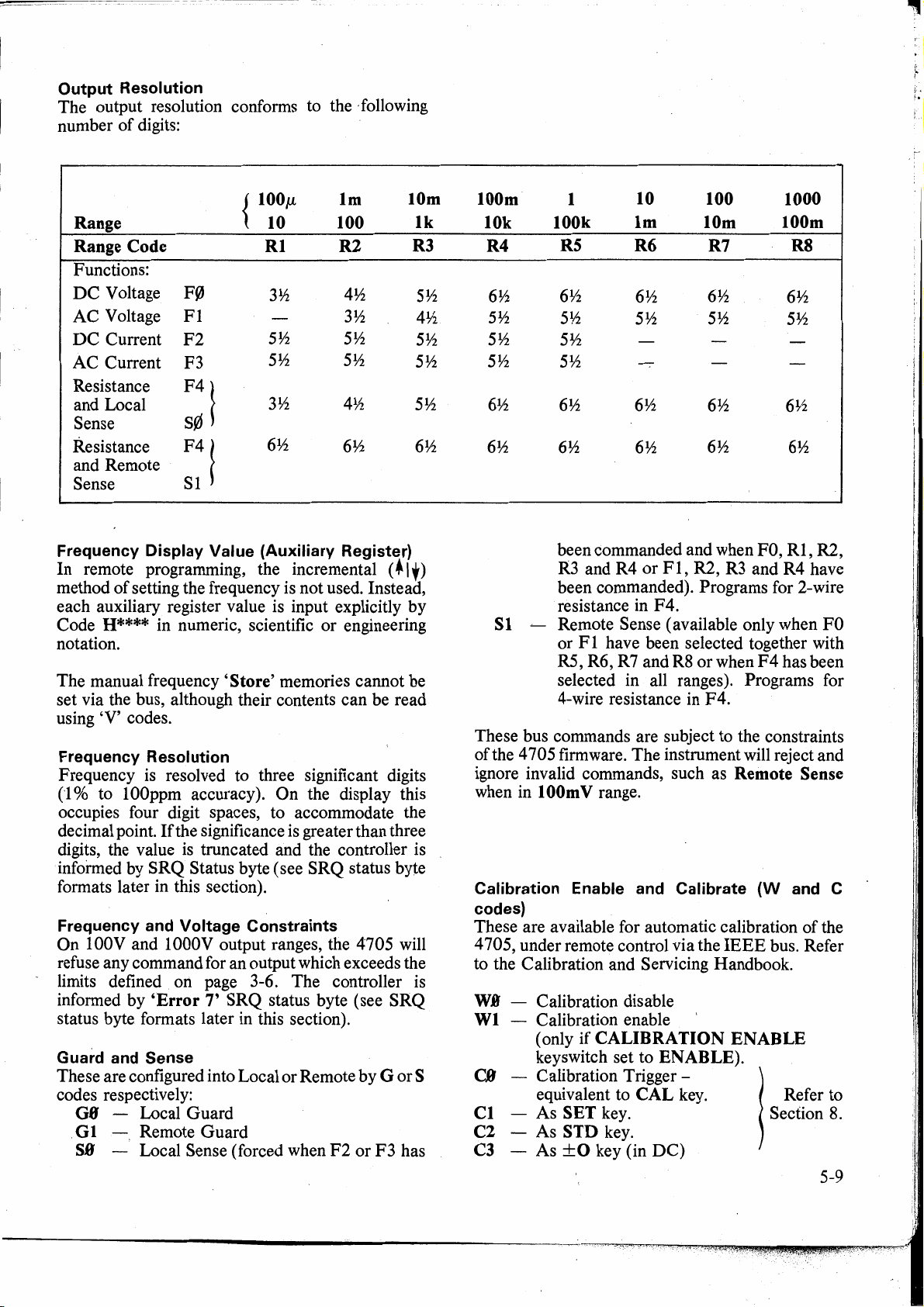
Output Resolution
The
output resolution conforms to the · following
number
of
digits:
{
100µ,
Range 10
Range Code
Functions:
DC
Voltage
AC
Voltage
DC
Current
AC
Current
Resistance
and Local
Sense
Resistance
and Remote
Sense
Frequency Display Value (Auxiliary Register)
In
remote programming, the incremental ( •
method
each auxiliary register value is input explicitly
Code
notation.
The
set via the bus, although their contents
using
Frequency Resolution
Frequency is resolved to three significant digits
(1
occupies four digit spaces, to accommodate the
decimal point.
digits, the value
informed by
formats later in this section).
Frequency and Voltage Constraints
On
refuse any command for an output which exceeds the
limits defined on page 3-6. The controller is
informed by 'Error 7' SRQ status byte (see SRQ
status byte formats later in this section).
Guard and Sense
These are configured into Local or Remote
codes respectively:
of
setting the frequency is
H****
manual frequency 'Store' memories cannot be
'V'
codes.
% to lOOppm accuracy).
lOOV
and 1000V output ranges, the 4705 will
G8 - Local
. G 1
-.
SB
- Local Sense (forced when
F~
Fl
F2
F3
F4!
S0
F4
!
S1
in numeric, scientific
If the significance is greater than three
is
truncated and the controller is
SRQ
Status byte ( see
Guard
Remote
Guard
Rl
3½
5½ 5½
5½
3½
6½
On
lm
100
R2
4½
3½
5½
4½
6½
not
used. Instead,
or
engineering
can
the display this
SRQ
status byte
by
F2
or
10m
R3
1,)
by
be read
G or S
F3
has
lk
5½
4½
5½
5½
5½
6½
100m
10k
R4
6½
5½
5½
5½
6½
6½
S 1
These bus commands are subject to the constraints
ofthe
4705 firmware.
ignore invalid commands, such as Remote Sense
when in
Calibration Enable and Calibrate
codes)
These are available for automatic calibration
4 705, under remote control via the
to the Calibration and Servicing Handbook.
- Calibration disable
W.0
Wl
- Calibration enable
- Calibration Trigger - '
C.0
-
Cl
C2
-
C3
-
1
100k
R5
6½
5½
5½
5½
6½
6½ 6½
been commanded and when FO,
R3 and R4
been commanded). Programs for 2-wire
resistance in
~
Remote Sense ( available only when
or F 1 have been selected together with
R5, R6, R7 and R8
selected in all ranges
4-wire resistance in
1
OOm
V range.
(only
if CALIBRATION
keyswitch set to ENABLE).
equivalent to
As
SET key.
As
STD
As
±0
10 100 1000
lm
R6 R7 R8
6½ 6½
5½ 5½
6½
or
F4.
The
CAL
key .
key (in
DC)
10m 100m
6½ 6½
6½
Fl,
R2, R3 and R4 have
or
when
).
F4.
instrument will reject and
IEEE
key.
6½
5½
6½
Rl,
F4
has been
Programs for
(W
and
of
bus. Refer
ENABLE
Refer to
1
1
Section 8.
'
R2,
FO
C
the
5-9
Page 61
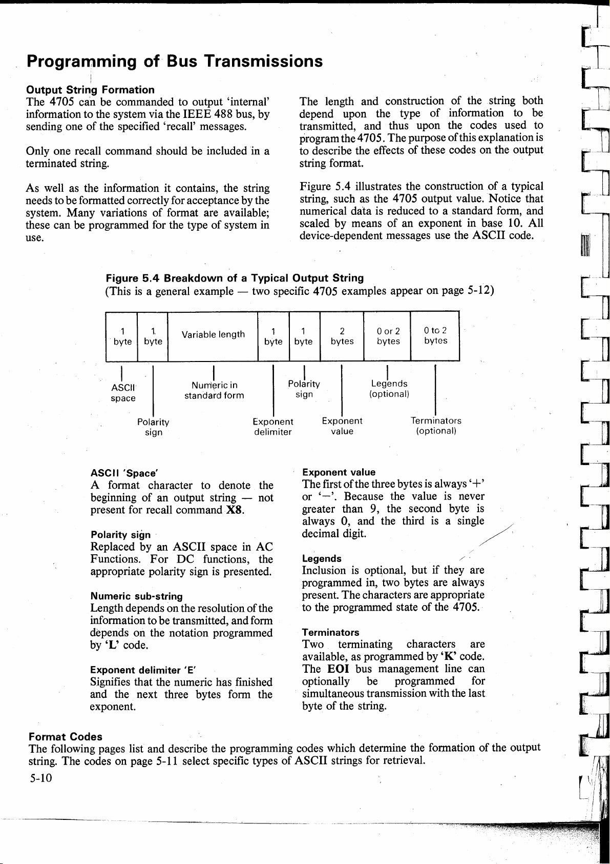
Programming of Bus Transmissions
!
Output String Formation
The 4705 can be commanded to output 'interna!'
information to the system via the
sending one
of
the specified 'recall' messages.
IEEE
Only one recall command should be included
488 bus, by
in
terminated string.
a
The length and construction
depend upon the type
transmitted, and thus upon the codes used to
program the 4705. The purpose ofthis explanation
to describe the effects
string format.
of
the string both
of
information to be
of
these codes on the output
is
As well as the information it contains, the string
needs to be formatted correctly for acceptance by the
system. Many variations
these can be programmed for the type
of
format are available;
of
system in
use.
Figure
(This
·
ASCII
space
ASC
1
byte
11
'Space'
5.4
Breakdown of a Typical Output String
is
a general example - two specific 4 705 examples appear on page 5-12)
l
byte
Polarity
sign
Variable length
I
Num'eric in
standa~d
form
Exponent
delimiter
A format character to denote the
of
beginning
present for recall command
Polarity sign ·
Replaced by an
Functions.
an output string - not
X8.
For
ASCII
DC
space in
AC
functions, the
appropriate polarity sign is presented.
Numeric sub-string
Length depends on the resolution
of
the
information to be transmitted, and form
depends on the notation programmed
by
'L' code.
Exponent delimiter
'E'
Signifies that the numeric has finished
and the next three bytes form the
exponent.
1
byte
Figure 5.4 illustrates the construction
string, such as the 4705 output value.
of
a typical
Notice
that
numerical data is reduced to a standard form, and
scaled
by
means
of
an exponent in base 10. All
device-dependent messages use the ASCII code.
0
to
1
byte
Exponent value
The first
or
2
bytes
Exponent
value
of
'-'.
Because the value is never
0 or 2
bytes
I
Legends
(optional)
Terminators
the three bytes is always '+'
2
bytes
(optional)
greater than 9, the second byte is
always 0, and the third
is
a single /
decimal digit. / ,
Legends / ·
Inclusion is opt~onal, but if they are
programmed in, two bytes are always
present. The characters are appropriate
to the programmed state
Terminators
of
the 4705.
Two terminating characters are
available, as programmed by 'K' code.
The
EO
I bus management line can
optionally be programmed for
simultaneous transmission with the last
byte
of
the string.
Format Codes
The following pages list and describe the programming codes which determine the formation
string. The codes on page 5-11 select specific types
5
..
10
of
ASCII
strings for retrieval.
of
the output
Page 62

Recall/Verify (code V).
By
sending a V code the controller interrogates the
4705 to obtain information about its present status.
Unless otherwise stated, the output strings are
formatted as programmed by
codes are as follows: \
VB
-
The
present Output value.
Vl
'.,__
The present Frequency setting
V2
- The present functional status.
The
response to
(space
The functions are represented by the same
numerics as for programming.
Output Range is identified
4705
V3·
The software status is the
number
as follows, in response to command code
R*F*O*G*S*W*Q*D*L*K*
is
programmed in autorange.
- Software status.
of
V2
is a standard
the internat program. This is formatted
K and L codes.
ASCII
In
addition, the
by
a lower case 'r' if the
part
number and issue
The
V
string:
terminator).
V3:
(space 890077 - numeric terminator)
A
A
Part No. Issue No.
(This status report is also available manually
by pressing
issue-number is presented on the
display).
V4
to
VS
Codes
held in volatile memory locations
can only be set or selected manually. (Refer to
page 3-7.)
The range
listed
under'
Codes)'.
1-code (Aide-Memoire)
This allows the user to identify a specific calibrator
with a designator up to 16 characters in length,
stored in non-volatile memory.
be placed in the
to
ENABLE
Sending the I command will store the subsequent 16
character string in memory. This string can be
recalled using the
N.B. The 1-command and the
not be sent in the same string.
Specification Tolerance (Per unit - P codes).
The
P commands give access to Spec mode over the .
Error key then
- 'Stored' Frequencies.
V4
to
VS
recall each
of
legends transmitted by the 4 705 is
String F ormattirtg Commands
CAL
mode by tuming the
and sending the
X8
command.
Lim-.
The firmware
MODE
of
the five frequencies
Fl
to F5.
(K
The
4705 must first
CAL
Wl
command.
Wl
command must
!hese
and L
key
bus, also setting the calibration interval:
PB
- 24 hour;
On
being commanded by P code, the
calculates the Output U ncertainty
( as a
Diagnostic Information
The X commands recall the contents
volatile calibration memory locations.
recalled are calibration constants stored at the most
recent Autocalibration. They are used in the
computations which establish the 4 705 output level,
as corrections for long-term drift in the analog
circuitry.
XB
Xl
X2
X3 Zero offset !
X4
X5
X6
X7
XS Recall message which was memorized
Activating the Recall Transmission
The 4 705 assembles the .appropriate output string in
its output registers in response to the
command.
bus by addressing the 4705 as a talker.
String Formatting Commands ( K and L Codes).
The output string can be formatted and terminated to
adapt to user's requirements. Scientific
Engineering notation can be programmed, with
'per
generates an output string formatted by K and
codes. Legends are transmitted as
Absolute Limits of Tolerance
In
this case, the O commands cause the 4 705 to
calculate the high
output value against the nominated calibration
interval.
U.0'
- Low limit
01
- Low limit
02
- Low limit 1 year
03
- High limit
04
- High limit 90 day
05
- High limit 1 year
On
being commanded, the calculated value is output
by the 4 705 in an output string formatted
codes.
Zero Cal. Store
Gain
calibration in
'STD'
Gain
Linearity(not
Reference Divider setting
Not
earlier by the operator using
Pl
-
90
day;
unit' fraction
or
24
90
Cal. Store in
calibration
error factory
used in 4705
It
can subsequently be released onto the
low limit
hour
day
24
hour
AC
AC)
of
P2
- 1 year.
of
its current state
the output value) and
pu
(per unit).
of
uncertainty
by
K and L
of
certain non-
The
valqes
DC,
LF
. gain +
· \
gai.
n facto
\
C?de
I.
V,
P,
0 or X
4705
L
of
its
HF
or
or
5-11
Page 63

without descriptive legends. Two examples are given
below.
LO
to
L3
Codes
configure the output string
notation:
I.B Scie·ntific notation with legends
Ll Scientific notation, no legends
·
L2
L3
Two sorts
a.
b.
Engineering notation with legends
Engineering notation, no legends
of
terminator are available:
One or two bytes can be added to the end
of
string. These contain either Carriage Retum
· (Cr) or Line
followed by
The
EO
Feed
(Lf); or both in the order:
Lf.
I bus management line can be
programmed to set true simultaneously with the
last byte
both
1.
Scientific
Bytes-
of
the string.
Cr
and
Lf
are suppressed.
Notation
(Codes
1 2 3 4
L,
EO
I can be used even if
and L 1
).
6
7
the
Cr
8
The 4705 can also be programmed to transmit
strings without terminators.
To
accommodate these
variations, the system programmer · uses the
codes:
KB
suppression (Cr,
Lf
and
EOI
No
present as terminators)
Kl
Suppress
EOI
(Terminator
Cr
followed by
Lf)
K2
K3
K4
KS
K6
Suppress
Suppress
Suppress
Suppress
Suppress
Lf
(Terminator
Lf
and
EOI
Cr
(Terminator Lf with EOI)
Cr
and
EOI
Cr
and Lf(Terminator
Cr
with EOI)
(Terminator
(Terminator Lf)
Cr)
EOI
last character)
Lf
and
9
K7
(No
10
11
Suppress Cr,
terminators).
12 13
14
EOI
15
16
17
18
K
all
with
Sp
Sp+
Two
ASCII spaces
or one space and
polarity
Outpllt
Value
Output Value Exponent:
Legend(s):
Terminator(s):
2.
Engineering Notation (Codes
Bytes -
Sp
Sp+
Two ASCII spaces
or one space and
polarity
Output
Value
Output Value Exponent:
Legends(s):
Termi.nator(s): (Gode K6 programmed.)
- 0/1
Num~ric:
· (In
2
- 0/1
Numeric:
(In this case L3 was programmed. i.e. no legends)
this
(Code
case
L2
3
0.000000
E±(0
code
K1
and
0.000000
E±(W
0-9 0-9
to
1.99999 9
to 9)
L~
was
programmed)
L3).
4
0-9
0-9
I
to
199.9999
10·
10')
programmed.)
6
0-9
I I
0-9 0-9
7
0-9 0-9 0-9
0-9
8 . 9
0-9
10
0-9
+I-
12
13
0
0
14
0
/3
/6
EOI
VAR
- EOI
with
line
last
E
11
E
+!-
0-9
SpN
byte
set
true
Cr
Lf
-
I
I
Descriptive Legends.
The following Legends will be fitted into the string after the exponent, if programmed by codes L0 or L2:
Recall Function
V0,
V0,
V0,
V0,
V0,
U0-U5
U0-U5
U0-U5
U0-U5
U0-U5
FO
Fl
F2
F3
F4
5-12
Legend Meaning Recall Legend Meaning
V
y,v
A
A,..,
DC
Volts P0-P2
AC
Volts
DC
Amps
AC
Amps
Frequency
pu per unit
Hz
frequency
R Resistance
Page 64

J
]
]
]
]
I
]
]
]
]
]
Service
The 4705 can asynchronously request service from
the controller by putting the
SRQ
the 4705 power ON, as the power-up defaultmode is
Request
SRQ line true (low).
is
always generated by the action of switching
QS.
A user can program the 4 705 to generate SRQs ( or
not) using command code Q:
QJJ
Code
Serial Poll and RQS Status Byte
If
programmed for
will pause in its operation to attend to the service
request.
determine which device initiated the
does not react to parallel poll, hut only to serial poll,
<luring
instrument responds to its serial poll address by
releasing a prepared
bus. The RQS Request Bit (bit
is
set true (Low) only if the 4705 has generated the
SRQ. This valida tes the remainder
which describes the causal condition by the state
codes listed in Table 5.5.
RQS Status Byte Composition
bit b8: Indicates a syntax error when true.
bit
bit
bit
- SRQ on any of the
Q 1 - SRQ on overload and any F
Table 5.5
Q2 -No
It
which each device
b7:
b6
true: Each combination
b6
false: Bits b5-bl each represent separate
SRQs generated
SRQ
response, the bus controller
first conducts a serial or parallel poll to
'RQS Status Byte' on to the
The RQS request bit, when true,
confirms that the 4 705 was the
originator. The RQS status byte
valid unless bit b7 is true.
represents a single state as listed in
Table 5.5
functional states within the 4705, and
RQS
the
as listed in Table 5. 5
byte represents several states
~tates
in Table 5
AIL
state
SRQ. The 4 705
is.
addressed in tum. The
B7
of its status byte)
of
the byte,
of
bits b5-bl
.5
in
SRQ
is
not
Example
RQS status byte 01000001 represents:
0 - Syntax error.
1 - This instrument originated the SRQ.
0 - The following bits each represent separate
0 - This bit
0 - N o High Voltage waming.
0 - Auxiliary register not
0 - Main register not at limit.
1 - Output
The RQS status byte should not be confused with
other status messages ( e.g. 'calibrator' or 'software'
status, described earlier under 'Recall/Verify')
which are called up by the system controller' s
program.
D10 Line Transmissions
Providing
4 705
sets the
status byte (
serial poll. On receiving the status byte, the
controller can address any device required to receive
the data as a listener, and address the 4705
talker. Then the message
programmed listener( s).
Fail Massages
The 4705 needs to react quickly to intemallygenerateq
take rapid protective action. A fault condition may
generate a train
occur too quickly for some controllers to detect.
Such a train may be terminated by a
message, which is detected by the controller. Thus
the receipt of F
as a final default condition, and not as indicating the
origin
cleared, if the 4705 has recovered, by pressing the
Reset key on the instrument front panel. As F
is
related to safety, it cannot be reset by remote
control.
with
bit b6 false:
states.
is
not used in the 4705.
at
limit.
is
ON.
QJJ
or Q 1 has been selected; when the
hasa
message to transmit over the
SRQ
line true and prepares the 'Recall' RQS
xl
100000) ready for the subsequent
is
sent via
F AIL messages and is programmed to
of
such interna! messages, which
AIL
5 by a controller should be taken
of
the fault. The F
AIL
D10
5 message can be
D10
lines, it
lines to the
FAIL
AIL
as
a
5
5
Page 65

Table 5.5 lists the possible
byte is valid only
if bit 7 (request bit) is true I
RQS
status bytes which may be transmitted by the 4705.
Legend: 1 = True, 0 = Fal se, X = 1 either 1 1or 0
bits
b8
1
X
b7 b6
1
X
1 X
b5
b4
X X
X
X
b3
X
X
b2
X
X
bl
Syntax! error
X
RQS
X
Combination Status Messages
X
1
0 X
X
1 0 X X X
X 1
X
0 X X 1
1 0 X 1 X X
X
X
Individual Status Messages
X 1
X 1
X
X
X
X 1
X
X
1
1
1 1
1
1
1
1
1
1 1
1
1
0 0
0
0 0 0
0 0
0
0 0
0
0 0
.1
0 0 1 0
0 0 1
0 0
1
X
1
X
0
0
1
1 1
0
1
1
Output'
1
Main l}egister limit reached
X
Auxili~ry Register limit reached
X
High
X
i
Recall 'message available
0
1
Error
Error 2 CAL
0
Error 3 CAL
Error 4 CAL
0
1 Error 5 Error or Offset mode: Overscale output requested
0 Error 6
Error 7
1
frequency constraints
X 1
X
X
X 1
X
X 1
X
X
X
X
X
X
X
X
X
1
1 1
1
1
1 1
1 1
1
1 1 1
1 1
1
1
1 1 1 1
1 1
1
1
1
1
1 1 1 1
1
1
1
0
1
1
1
0
0 0
0 0
0
0 0
0
0 0 F ail O F ault condition rectified
0
·o
1
1 1 F ail 3 Control data corrupted
0
1 0 1 0 0
1 0
0
0
0
0
1
1
0 0
0
1 1
1 0 1
1 0 1
1
1
1 1
Error 8 General selection error
1 Fail 1 Over-temperature
Fail 2 Over-voltage
0
Fail 4 Precision divider fault
1
Fail 5 Safety alarm
Fail 6 Cal. store sum check non-parity
0
1 Fall 7 400V power supply fault ( automatically resets if temporary)
Fail 8 3V power supply fault
1 Fail 9 15V ln-guard power supply fault
Reset. Instrument reset to power-up state
1 1 1 0 0 Error
1
1
1
1
1 1 Power-on
1
Overload - Current or Voltage limit
0
!
I
I
Request-for-service bit
i
I
I
I
ON
"Y:
oltage W
I
:
arning_
1 Specification not displayable
mode: Output not
ON
mode: Incorrect Range/Function
mode: Insufficient store span
CAL
mode: Resistance selected exceeds val. value
AC
Functions: Output has been limited by internat
EF
Externa! frequency not present
The
information in the
Table
5.5
Notes: (
Status Byte Coding
1) Power-up condition:
D0 F0 G0
K0
L0
M0
00
Q0
R0
(lV)
Device clear condition as power-up but K = and
'='
(2) Program string terminator:
activates preceding string.
S0
W0
L=
continue unchanged
Page 66

Activation of Commands
Use of Terminator
The 4 705 activates single or multiple commands,
only on receipt
the
ASCII character
of
the recognized terminator. This is
'='.
Commands or command strings may be received
while the instrument is in Local control, but will not
is
be activated even if a terminator
present, until the
instrument is set to Remote control. The two 'Clear'
messages
(DCL
and
SDC)
will be activated even
when in Local control.
Multipla Commands
Activation sequence
The input buffer has a capacity of 128 characters.
Commands in a multiple string may be entered in
any order, provided correct character syntax is
observed. They are extracted from the buffer in
received sequence and stored by alpha character into
Any
command stores.
store are over-written and lost.
When a string terminator
in the store are validated. V alidation ensures that the
proposed instrument state ( consisting
changes programmed and those current states not
reprogrammed) is valid.
string being ignored and a syntax error generated.
New commands are executed in this sequence:
K Output terminator format
L Output notation
Q
SRQMode
W Remote Calfbration Enable
I U ser Message lnput
00
OUTPUT
OFF
G Guard
D Safety Delay override
F Function
R Range
M Main Register Value ( Output)
A Full Range/Zero
S Sense
H Auxiliary Register Value (Frequency)
01
OUTPUT
ON
C Calibrate Mode
P Specification tolerance
U Specification limits
V Recall/Verify
X Diagnostic information
existing commands in the
is
received, the commands
of
those
Any
error results in the
A programmer may elect to change the sequence by
_inserting
.
basic constraints
For
command (e.g.
will set
re-programmed
, Succession of Multiple Commands
If
the input buffer
accepted to await their
terminators between commands, but the
of
the 4 705 will still be imposed.
example, if the function
F3=)
Output O
FF
as a result, and it must then be
ON
by the user.
is
not full, new commands are
is
changed as a single
the main program firmware
tum
for processing, and are
extracted string by string. The input system design
makes it extremely unlikely that the buffer will
overflow, unless the 4705 is in Local Control and the
is
command input
fill
buffer to
up, the 4 705 places a hold on the
excessive.
bus handshake sequence. The command
used to release the hold, followed by
If
this does cause the
IFC
DCL
to clear
IEEE
can be ·
the 4705 input buffer; but as·a general principle, this
situation should be avoided by suitable
'reprogramming.
lnput Errors ,
Some unwanted commands are ignored. Others
enter the input buffer, and are rejected later.
'Read' commands
Before addressing the 4705 as a talker, it
that it has been programmed by a
P,
is
essential
U,
V or X
command. Otherwise it will have no data to
transmit.
Universal commands
LLO (Local Lockout) - ignored, no capability.
PPU
(Parallel Poll Unconfigured) - ignored, no
capability for parallel poll.
SPE (Serial Poll Enable) - sets the 4705 to serial
poll state, which when addressed responds
with the RQS status byte. This byte contains
the condition ofthe request-service bit (bit 7).
If
the 4 705 is requesting service; bit 7 will be
true, the other bits describing the service
required.
SPD (Serial Poll
Disable)-
returns the instrument
to serial poll idle state.
Addressed commands
PPC (Parallel Poll Configure) - ignored, no
capability.
GET (Group Execute Trigger) - ignored, no
capability.
TCT (Take Control) - ignored, no capability.
GTL
(
Go
To
Local)-
instrument returns to Manual
Control. The controller regains remote
control by addressing the 4 705 as a listener
REN
with
line true. \
5-14
Page 67

11
I
Il
]]
I
I
I
Clear Commands
When the 4 705 receives either of the two 'Clear'
messages,
to a selected device) it will default to the
predetermined state defined below. During the time
taken to default, the
held. These commands are effective even in 'Local'
control.
A?
FP
R~
MjJ
H(value)
o,
S'1
00
Q"
D9
Wft
c'i
P?
U?
V?
X?
K*
L*
The frequency values held in 'Store' volatile
memory locations F
state described on page 3-
(DCL
Not Active ( see M code)
DC
Autorange 1 V default
Where value
. Where value is
Local guard
Local sense
OUTPUT
SRQ
Safety delay active
Calibration disabled
Not
Not
Not
Not
Not
Unchanged
Unchanged
(DCL
is universal and
Volts
on all specified states
active _:·disabled by
active
active
active
active·
and
SDC)
SDC
IEEE
1-
interf ace handshake is
is
zero
lkHz
OFF
state
F 5 are reset to the default
7.
is
a:ddressed
W0
Operational. Sequence
Guidelines
Most interf ace communication tasks require
sequences of coded messages to be sent over the
interf ace. Many · controllers assign a single
programming instruction to a complete sequence, so
it
is
advisable to study the available controller
capabilities carefully before attemping to program a ·
system. Because the
certain latitude in bus protocol, considerable
differences may be found between programming
instructions and operating sequences from one make
of controller to another. Consequently, the following
sequences are recommendations only.
IEEE
Std 488 (1978) allows a
Data Transfer
UNL
LAD1 Each address sent enables a specific
LAD
Inhibits all current listeners
device to receive future data bytes.
More than one address · may be sent if
0
multiple listeners desired. ·
I
TAD
DAB1
The address sent enables a specific
4
705
device to send data. The
already programmed to prepare data.
Data
talkers to all currently-enabled listeners.
bytes sent by currently-enabled
must be
I
DAB
0
UNT
UNL
LAD
T
AD
DAB
UNT
Serial Poll
UNL
SPE
TAD
SBN
or
SBA
SPD
UNT
SPE
SPD
SBN
[
SBA
Untalk
It
is
highly desirable that a sequence which causes a
device to be addressed as a talker should be
terminated by an 'untalk' command.
Disables the talker on receipt of the last
character.
= unlisten
= listen address
= talk address
= data bytes
of
specific device
of
specific device
= untalk
Inhibits all current listeners
Puts interface into serial poll mode
<luring
instead of data when addressed.
Enables a specific device to send status.
0
Within this loop, device should be
sequentially enabled.
which all devices send status
l Status byte sent by enabled device:
~
lf
SBN, loop should be repeated.
sent, the enabled device
having sent
remove
Disables serial poll mode.
Disable last talker.
it.
SRQ
and will automatically
is
= Serial poll enable · l
= Serial poll disable
= Status byte negative where bit 7 = 0
= Status byte affirmative where bit 7 = 1
If
SBA
identified
as
..
'
5-15
Page 68

SECTION 6 SPECIFICATIONS
General
POWER SUPPL V
Voltage
Line Frequency
~
Consumption
Fuses 2201240V
100!120V
100/120/220/240V±10%
48Hzto62Hz
370 VA normal
660 VA full power
3.15A
6.25A
MECHANICAL
Dimensions
Weight
SAFETY
PEAK
TERMINAL VOLTAGES
Guard to Ground 920V
Loto Guard 920V
Loto Ground 920V
Hi
to
Guard 1556V
Hi
to
Ground 1556V
Rear Panel Digital lnputs-
Hi
to
Lo
to
to Guard 920V
toGround
Height 178mm (7")
Width 455mm (17.9")
Depth 564mm (22.2")
35kg (77Ib)
The 4 705 has been designed
to meet BSI 4743, IEC 348
and UL 1244 specifications
1556V
920V
0Vto
+5V
N.B.
Digital Common is internally connected to Ground
ENVIRONMENTAL CONDITIONS
Operating temperature :
0°C
to +50°C
CAUTION.
Above 30°C on 1 kV Range: maximum output power is derated
-40°C
Storage Temperature
Maximum Relative Humidity 75% at 40°C
Warm-up Time One hourto meet
to + 70°C
Non-Condensing
all
specifications
OPERATING INDICATIONS
lndication Symbols lit on displays and
Scale Lengths
Output Display 6
Frequency Display 3 Digits plus store location
Mode Display
illuminated keys
1
/?
Digits maximum
1
/?
Digits maximum
6
6-1
Page 69

DCVOLTAGE
Accuracy
Range
100.0µVto
100.0000mV
1.000000V
10.00000V
100.0000V
1000.000V
Stability
24 hour
±(ppm
OUTPUT+
ppmFS) 24 hour
(1) (2)
2+1µV
2+1
1+0.5
2+0.5
2+0.5
Noise (4)
Bandwidth 2.5kHz Average
1V
(RMS)
4µV
4µV
10µV
120µV
2.5mV
Range
100µV-100mV
10V
100V
1000V
Accuracy Relative to Calibration Standards Calibration
±(ppm
OUTPUT
23 C
±
1'C
6+1µV
6+1
6+1
6+1
6+1
Over
1 Line Period
(pk-to-pk)
0.2µV
2µV
5µV
50µV
600µV
+ppmFS)
90days
23''C±
1''C
15+1µV
15+1
15+1
15+1
15+1
Average
1 O Line Periods
(pk-to-pk)
0.5µV
0.5µV
25µV
200µV
(2)
1 year
23"C ± 10°C
35+5µV
35+5
35+5
35+5
35+5
Over
2µV
Uncertainty
(ppm)(3)
1Ö+1µV
7
5
9
12
DC-2Hz
(Typical Null
Detector)
(pk-to-pk)
0.1µV
0.5µV
2µV
25µV
150µV
Temperature
Coefficient
OUTPUTl°C)
8°C-
33°C
-,
2.0
1.5
1.0
1.5
2.0
(±ppm
13°C
38r'C
Output Output
Reslstance Compliance
1000
<0.1m!!
<0.1m!!
<1m!!
<10mH
-
25mA
25mA
25mA
25mA
Notes:
(
1)
For same conditions between 18
(2)
FS=2xRange
(3)
Factory calibration uncertainty using automated calibration equipment.
Datron can provide better traceability. Contact factory for details.
(4)
For 10kHz-wide band, multiply 2.5kHz figures by
·c
and 28' C
2.
For RMS, divide pk-to-pk figures by 6.
Other Specifications
Output
Overrange
Voltage Sensing
Guarding
Common Mode Rejection
Settling Time
True bipolar output capable of delivering
100%
on
100µ
V to 1
OOV
ranges, 10% on 1
Selectable remote or local voltage sensing on 1 V to 1
Selectable remote
140dB at DC to 400Hz.
To 1 ppm of step size
To 1 Oppm of step size
To 1
OOppm
or
local guard connection. Max Guard to Ground voltage of 650V rms (2.5kV flash test).
<5s.
of step size < 1
<1
s.
OOms.
6-2
11
OOV
with respect to Output Lo.
OOOV
range
(11
OOOV
OOV).
ranges.
;o··
I .
l
Page 70

,.
----··'
'
·-
-,
- .
DANGIR
HIGH VOLTAGE
.
Lt
THIS
..
INSTRUMENT
OF DELIVERING
A
llTHAl
IS CAPABLE
EllCTRIC
Guard terminal is
sensitiva
voltage
SHOCK
to
over -
!
,.
Unless
,
-DO
I+
.
It
your
you
it
is safe
can
instrument!
.are
damage
sure
to
do so,
NOT TOUCH
I-
and
Hi
or
Lo leads
terminals
DANGIR
that
the
Page 71

ACVOLTAGE
'~!(:
Accuracy
Range
1.000mV
to
100.000mV
1.00000V
and
10.0000V
100.000V
1000.00V
Frequency Stabil ity
(Hz)
10-31
32-33k
30k-100k
10-31
32-33k
30k-100k
10-31
32-33k
30k-100k
45-330
300-10k
10k-33k
24hour
±(ppm
OUTPUT
+ppmFS)"
(1) (2)
170+10+10µV
80+10+10µV
80+10+10µV
150+
20
80+
10
80+
10
150+20
80+10
80+
10 .
150+20
80+20
150+30
Accuracy Relative to
24hour
23°c ± 1°c
250+60+10µV
200+60+10µV
800+80+10µV
250+60
200+50
250+80
250+60
200+50
250
+80
250+60
200+50
250+80
±
(ppm
Calibration
OUTPUT +
23°c ± 1°c
300+60+10µV
250+60+10µV
800+80+10µV
300+60
250+50
300+80
300+60
250+50
300+80
300+60
250+50
300+80
ppm
90days
Standards
FS)
(2)
23°c ± 10°c
400+60+10µV
300+60+10µV
0.1%+60+10µV
1
yea·r
400+60
300+50
500+80
400+60
380+50
500+80
400+60
300+50
500+80
-iiw
I
:---'-':-
~
~
Notes:
(1)
For same conditions between 18 C and 28
(2)
FS=2x
Range.
(3)
Factory calibration uncertainty using automated calibration equipment. Datron can provide better traceability. Contact factory for details.
(4)
Estimated. not fully traceable.
(5)
fredominantly
(6)
For Frequency Range or Output Range changes. Function changes. OFF ON changes. and Frequency changes between
S_ettling
•
In
remote operation via the IEEE 488 lnterface. hardware switching occurs under the control of 'H' (Frequency) codes. Any transfer (up or
down) between the undermentioned frequencies must be regarded as a frequency range change. Settling Time should be allowed as for
·other
•
For
se~ling
second harmonic (negligible error on mean sensing instruments).
Times are doubled.
Specifications. · ·
300-301Hz
3-.00
33.0 -33.1 kHz
to 1 Oppm
of Step Size,
·31
-32Hz
-3.01 kHz
multiply
C.
all
times
by
31
1 .5.
and 32Hz: the
6-4
Page 72

Calibration Temperature
Uncertainty (ppm)
(3)
Coefficient
(±ppm
33
OUTPUT
C-13··c
8
C-38
Total
Harmonic
''C)
C
Distortion
(%)(5)
Output I mpedance
at Zero to Full Load
Regulation
Output
Compliance
110+12µV
250+10µV
560+11µV
160
130
170
160
130
200(6)
190
170
250
Other Specifications
Scale Length
Voltage Sensing
Guarding
Common
. Settling Time (6)
Frequency Accuracy
Maximum Load
Capacitance
Mode Rejection
10
10
10
6
6
6
6
6
10
10
10
10
9%
to 200% of Range, 1 mV to 1 00V ranges.
9'%
to 110% of range, 1 000V range
Selectable remote or local voltage
sensing on 1 V to 1 000V ranges.
Selectable remote or local guard connection. Maximum Guard to Gound voltage
140dB at DC to 400Hz.
To 1 00ppm of step size (double for range changes);
1 0 -
32Hz< 1 Os.
32-
330Hz<3s.
>330Hz<1s.
< 100ppm, typically < 10ppm.
1 V to 1
00V
1 000V range: 300pF.
ranges: 1 000pF.
0.1
0.04
0.1
0.1
0.04
0.1
0.1
0.04
0.2
0.2
0.1
0.1
30H
at all frequencies
Typically
0.001% FS
to33kHz
increasing to
0.02% FS at 1 00kHz (2)
Typically
0.002%FS
to33kHz
increasing to.
0.02% FS at 1 00kHz (2)
Typically
0.002%FS
(11
to33kHz
00V).
(2)
. -
1 V Range:
10V Range: 60mA
<3.3kHz,
>3.3kHz,
25mA
120mA
15mA
65mA
650V
RMS (2.5kV flash test).
6-5
Page 73

VOL TAGE/FREQUENCY CONSTRAINTS
1000V
Output
Voltage
(Log. Scale)
200V
100V
20V
10V
Frequency
Range Spans
100Hz Range
45Hz
1300
330
I
-----------'
I·
1kHz Range
3.3k I
_10kHz
Range
! 3k 33k I
I
3ok
33kHz
I
I
100kHz Range
100k I
100kHz
1100V
1000VRange
200V
90V
100V Range
20V
9V
6-6
1V
10V Range
(Lower
Ranges
also cover
thefull
frequency
span)
0.9V
10
30
-I
100
300
Output
I I
I
1 k 3k
Frequency
(Hz)
(Log. Scale)
10k
30k
100k
Voltage
Range
Spans
Page 74

CAPACITIVE LOADING CONSTRAINTS
.8
6
Volt-
Hertz 3
7
X
10
Volt-Hertz Power Lim it versus Capacitance Load
7
5
4
2
Full Specification
specification
100
200 300 400 600 800 1000
I•
i
ii
-
,
...
(1
kV
Range}
4-wire:
11111
11111 1
11111 1
Il
11111 1
typical
I
I
I
-
,2,-vy)re
-
I
Il
...
"'-
~
"'1111
..
~
~
I
Not
..
(>1000pF)
Vaiid
~i,..~i,..-
.....
_
...
Total Load Capacitance - lncluding Leads
(pF)
6-7
Page 75

'oc
CURRENT
Accuracy
(
Range
OUTPUT+
100.000pA
1.00000mA
10.0000mA
100.000mA
1.00000A (4)
Noise
2.SkHz Average Over
(RMS)
5nA 6nA
SnA
50nA 30nA
.1µA
25µA
Stab11ity
24 hour
±(ppm
ppmFS)
(1)
15+10
15+10
15+10
15+10
15+15
Bandwidth
1 Line Period
(pk-to-pk)
500nA 400nA
30µA
Accuracy Relative to Calibration Standards Calibration
±(ppm
OUTPUT
(2)
6nA
24 hour
C±
23
20+15
20+15
20+15
20+15
20+20
Average Over
1
O Line Periods
1 C
(pk-to-pk)
2nA
2nA
20nA
20µA
+ppmFS)
90days
23 C ± 1 C
50+15
50+15
50+15
50+15
115+20
(2)
1 year
23
C±
115+20
115+20
115+20
115+20
250+30
10 C
Uncert_ainty
(±ppm)(3)
a,,;,f~_,,h,l.
35
33
33
33
80
T emperature
Coefficient (
OUTPUT'C)
a··c-13C
33'C-38C
30
12
12
12
30
±ppm
Output Output
Resistance Compliance
>2G!!
>2GU
>200MU
>20MU
>1MU
3V
3V
3V
3V
3V
.f'
Notes:
(1)
For same conditions between 18°C and 28°C.
(2)
FS=2xRange.
(3) Factory calibration uncertainty using automated calibration equipment.
Datron can provide better traceability. Contact factory for details.
(4)
Typical above 1A.
Other Specifications
Output
Overrange
Settling Time
Local Sense Only. all ranges
Max.
reactive loads
True bipolar output capable
100% on all ranges.
sto
full specification.
1
1mH(<1µs).
100nF,
of
delivering
6-8
±2A.
I
~
Page 76

\,
\
]
],
,.
THIS
...
HIGH
INSTRUMENT
OF DELIVERING
A
llTHAl
~•(
DANGIR
VOLTAGE
IS CAPABLE
ILICTRIC
FRONT
C terminals
Full
or
Output
SHOCK
REAR
carry
the
Voltage.
.Lh_; ....
_.
I
•
I •
THIS CAN KILL !
Guard terminal is
to
sensitive
voltage
It
can
your
r
Unless
DO
I+
you
it
is safe
NOT
I-
Hi
_instrument!
are sure
TOUCH
or
damage
to
do so,
Lo leads
over -
that
the
I·
and terminals
DANGIR
6-9
Page 77

ACCURRENT
Ac.curacy
Range Frequency
100.000µA
1.00000mA
10.0000mA
100.000mA
1.00000A(4)
(Hz)
10-1
1k-5k
10-1
1k-5k
10-1
1k-5k
10-1
1k-5k
10-1
1k-5k
---
Stabil ity
24hour
±(ppm
OUTPUT
+ppmFS)
(1) (2)
k
k
k
k
k
50+20
70+30
50+20
50+20
50+20
50+20
50+20
50+20
50+20
70+30
23°c + 1°c
400+80 400+80
550+100
200+80
350+80
200+80
350+80
200+80
350+80 350+80
400+80
550+100
Accuracy Relative to Calibration Standards
± (ppm OUTPUT + ppm
24hour 90days 1 year
(7)
(7)
23°C+
550+100
220+80
350+80
220+80
350+80
220+80
400+80
550+100
1°c
(7)
(7)
FS)
(2)
23°C+
500+100
650+160
350+100
450+100
350+100
450+100
350+100
450+100
500+100
650+160
10°c
(7)
(7)
[---
t]
-~
-,
n
r---~
]]
Notes:
(1)
For same conditions between 18°C and 28°C.
(2)
FS=2x
Range.
(3)
Factory calibration uncertainty using automated calibration equipment. Datron can provide better traceability. Contact factory for details.
(4)
Typical above 1
(5)
Predominantly second harmonic (negligible error on mean sensing instruments).
(6)
For Frequency Range or Output Range changes, Function changes, OFF
~ettling Times are doubled.
In
remote operation via the IEEE 488 lnterface, hardware switching occurs under the control of 'H' (Frequency) codes. Any transfer (up or
•
down) between the undermentioned frequencies must be regarded as a frequency range change. Settling Time should be allowed as for
'Other Specifications. · ·
• For settling to 1
(7)
Assumes similar load time constant to that at calibration.
A.
.31-32Hz
300-301Hz
3.00 -
3.01
Oppm
of Step Size, multiply all times by 1.5.
kHz
33.0 -33.1 kHz
330-331kHz
1
0N
changes, and Frequency changes between
31
I
and 32Hz: the
6-10
Page 78

I
J
Calibration Temperature
Uncertainty (ppm)
(3)
400
900
255
255
255
255 20
255
255
290
440 40
* Typical effective output capacitance = 200pF } Negligible on other Ranges.
** Typical effective output capacitance = 0.5µF
Coefficient
(±ppm
OUTPUT'°C
3°C-13°C
33°C-43°C
20
40 0.5
20
·20 0.2
20
20
20
40
Total
Harmonic Output
Distortion lmpedance
(%)(5)
0.2
0.2 30MH
0.2 3MH
0.2
0.2 300kH
0.2
0.2 30kU**
1.0
Typical
100MH*
Output
Compliance
3Vrms
3Vrms
3Vrms
3Vrms
3Vrms
Other Specifications
Scale Length
Settling Time (6)
Frequency Accuracy < ± 1 00ppm, typically 1
Maximum Load Capacitance 1
Maximum Load lnductance 1 mH ( < 1 µs)
Local Sense Only, all ranges.
9% to ~00% of range, all ranges.
OOppm
To 1
OnF ( <1
of step size ( double for range changes):
10-32Hz<10s
32-330Hz<3s
>330Hz<1s
µs).
..
Oppm.
I:
6-11
Page 79

RESISTANCE
Accuracy
10.ooooon
100.0000!l
1.000000k
10.00000k
190.0000k
1.000000M
10.00000M
100.0000M
* 2-wire Sense 24 Hrs and 90 days stability }
Range
(1)
(2-wire
or
4-wire
Stabil ity Accuracy Relative to Calibration Calibration Temperature
* 24 hour
±(ppm
OUTPUT
+ppmFS)
(1) (2)
l..._
10
2.5
2.5 3
2.5
2.5
8
30
sense)
Standards
OUTPUT
±(ppm
24hour
·
23°c ± 1°c
12
3 6
3
3 6
10 25 60
40 100 200
+ppmFS)
90days
23°c ± 1°c
30
6
6
(2)
1 year
l23°C
± 10°C
75 25
20
20 10
20 10
25 20
40 50 125 500 200
90 days accuracy
1 year accuracy
4-wire values
4-wire values
±0.1
±o.2n
Notes:
(1)
Range figures are nominal, actual calibrated values are displayed.
(2)
FS=2xRange.
(3)
Factory calibration uncertainty using automated calibration equipment.
Datron can provide better traceability. Contact factory for details.
Uncertainty Coefficient
(ppm)
(3)
Os~lterltei-
1
10
40
65
n
OUTPUT/°C)
(±ppm
8°C-13°C
33°C-38°C
6
2
2
2
2
6
10
20
Specified Maximum
Addition
Current Current . uncertainty
(Is) (lm)
forls~l<lm
(ppm)
(8.5x10
(~.5x10
(a.sx10
(15x10
(15x10
2
1
8
9
10mA 100mA (10x10
10mA
25mA
1mA 10mA
100µA
'100µA
10µA
1µA
1µA
2.5mA (8.5x10
1mA
100µA (10x10
10µA
10µA
al
12
)
3
12
)
4
)
12
5
)
12
6
)
12
)
12
2
)
1
)
12
Other Specifications
Connection
Guarding
Protection All resistors fuse protected to max applied voltage of 120V RMS.
Selectable 2 or 4-wire connection to resistors.
2-wire displayed value includes interna! lead resistance.
or
Selectable remote
local guard connection.
6-12
Page 80

I
i
]
I
J
l
l
l
l
l
SECTION 7
SPECIFICATION
lntroduction
The factory calibration of the 4705 ensures
trac.eable accuracy to national standards. Figures of
performance are quoted in the specifications of
Section 6, related to time since calibration.
This section deals with user-verification ofthe 4705
perf ormance to specification.
as
two independent vertifications:
AC
and then
specification.
It should be carried out
DC
specification
DC Specification Verification
Verification upon receipt of a 4705 Autocal
Multifunction Calibrator
Each instrument leaving the factory
DC
its nominal values in
to actual values in Resistance. The Accuracy
specifications can be roade relative (i.e. Traceable)
to National Standards, by the addition
Calibration Uncertainty figures printed in the
specifications. Thus either the 90-day or 1-year
accuracy specification
with traceable Reference Standards.
The 24:-hour stability specifications can only be
verified following a calibration operation or
calibration check against the user' s Reference
Standards.
voltage,
is
verifiable by comparison
is
calibrated to
DC
Current, and
of
Datron's
, Equipment Requirements
VERIFICATION
DC
Current - A
N.B. To allow the same value to be set on
CAUTION When choosing a set
DC
Voltage source, calibrated to
at
suitable accuracy
lV
and lO0mV. ·
Example: The standard voltage
source used for
Voltage, with the. Datron
4903
- The battery-operated null detector
DC
used for
- A set
- altematively, a D
of
suitable accuracy.
DC
the
range, the . shunts may be of
decade values. Then the same Null
Detector sensitivity can be used on
each range.
shunts ensure that their power
dissipation· ratings are sufficient to
avoid permanent degradation from
the self-heating effects
being checked. This applies
particularly to the 1 Amp shunt.
accuracy may be
the voltage across the set of
calibrated current shunts.
Example: Datron l081 using
Voltage.
calibrated current shunts of
Voltage source for each
"compute" mode.
approximately
DC
Switching Unit.
of
of
the current
MM
of
us'ed
to measure
DC
five
current
sufficient
DC
Voltage - A Standard
suitable accuracy
Example: Series bank of 10 standard
- A Precision Divider
Example: Datron 4902 High
- A battery-operated null detector
I
with variable sensitivity, able to
withstand 1200V across its input
terminals
Example: Keithley Instruments
DC
Voltage source of
cells and Datron 4904
Staridard Cell buffer.
Voltage
divider and Datron 4903
DC
Switching Unit
· Model 155
Resistance - a set of standard resistors covering
100
to
lOOMO.
should be 4-wire type.
- an acc:urate resistance bridge, or
other ratiometric device for
measuring resistance to the required .
accuracy.
- a Datron 1081 used as a transfer
measurement device.
The
100
to lOkO
7-1
.
..
;
."·.
Page 81

~r
[ .
Notes
on
the Use of the
Null Detector
The null detector is connected in the
DC
between the
high-input-impedance device should be chosen to
reduce off-null currents due to differences in the
outputs of the
battery-operated instrument
adequate isolation. Some null detectors possess high
input impedance only when their readings are onscale, so care should be taken to ensure that drain
currents from the
excessive. This applies particularly if the
isa
standard
important:
l.
The null detector should be connected to the 4705
{or 4705 load resistor in Current function) only
when the 4 705
Output
at high impedånce
2.
Always
sensitivity before connecting up, and increase
sensitivity only when the voltages output by the
DC
value.
OFF, the
Voltage source and the 4 705 are close in
Voltage Source arid the 4705. A
DC
voltage source and the 4 705. A
is
preferred to ensure
DC
Voltage source do not become
cellor
set
a bank
OUTPUT
I+,
).
the null detector to its lowest
I-,
of
cells. Five points are
OFF
LED
Hi
and Lo terminals are
Hi
DC
source
is
lit. (With
lead
~pecification Verification
Report Sheet
The verification procedures in this section use the
+ Lim and - Lim facilities
. written table of tolerance limits
most cases, users will wish to verify against
Reference Standards at non-cardinal values, so a
table of Full Range limits would have little value.
Instead of Limit tables, a Report Sheet is provided
later. This can be used for recording the results
verifying any of the three stored specifications.
Spaces are provided to record the displayed limits as
well as the measured values. The sheet may be used
as a master to generate duplicate copies for future
use.
Stored Specifications
Three specifications are stored within each 4
instrument's non-volatile memory:
24-hour accuracy,
90-day accuracy
1 year accuracy + Datron' s Calibration
+ Datron's Calibration
of
S pec mode, so a
is
unnecessary.
U ncertainty
, Uncertainty
In
of
705
]J
:n
.
'l
3.
Do
not change polarity of the 4 705 or
source without first switching the 4 705
0 FF. Care must be taken to ensure that the
ON
key
is
correct-polarity
excessive voltages being connected across the null
detector, particularly when checking the 4705
directly against a standard cell.
4. W ARNING
5.
CAUTION
7-2
· During Performance checks and
calibration a common mode
voltage equal to the full
range voltage is present at the
Null Detector input terminals. ,
On
+ 1
OOOV
is
potentially lethal,. so
EXTREME
be . observed when making
adjustments
· · sensitivity.
The N ull Detector used must be
able to withstand voltages up · to
1200V between · its input
terminals. Such voltages will be
present
4705 is ramping from zero to _
1000V Full Range · after setting
OUTPUTON.
<luring
pressed, to avoid
checks this voltage
CAUTION must
to
DC
Voltage
OUTPUT
the null detector
the time that the
These are selectable by the CALIBRA
INTERV
accessible to users by selecting 'Spec' mode (Refer
to Sections 3 and 4
tolerance and limit figures which are trå.ceable to
National Standards.
4700
The 'Spec' mode 24-hour accuracy limits are
computed from their specifications in Section
displayed 90-day and 1-year accuracy limits for the
4705 are given at 23°C
respectively. They include Datron's calibration
uncertainty, hut not the
uncertainty. This should be taken· into account if
appropriate.
Non-Verification
If
an instrument
refer to the Routine Autocalibration in Section 8, or
contact your nearest Datron Servicing Center.
N.B.
AL
switch on the rear panel, and are
).
Thus 'Spec' mode provides
Tolerance Limits
+ 1 °C and 23°C +
is
found to be out of specification,
It
is recommended
Sheets be duplicated to
use.
that
use.r'
s calibration
the Blank Report
give
copies for future
TION
6.
The
10°c
-
,--
Page 82

Verification Pro·cedures
A
full
verification should be carried . out in the
sequence appearing on the Specification
Verification Report Sheet. The instructions which
follow are divided into 4 procedures:
DC
Voltage Full Range
DC
Voltage Linearity (lOV Range only)
DC
Current Full Range
Resistance
The displayed limits do not include temperature·-
coefficient corrections or the user' s calibration
uncertainties which should be taken into account
this
is
appropriate.
4705
DC
Voltage
Performance
CAUTION: First read the notes on the use of the
Null Detector (page 7-2).
1.
Tum
on the instrument to be checked and
minimum
environment. ·
2. Cancel any
check that
display.
of
4 hours to warm-up in the specified
MODE
cal
keys, set
is
not present on the
OUTPUT
&llow
OFF
MODE
and
if
a
Tum
to the voltage source down to zero and allow
the circuit to stabilize
N.B. When changing polarity
leads are reversed it willbe necessary to allow
time for thermal effects to stabilize in the
reversed connection before proceeding with
the check.
5.
Full Range Checks
Press S pec Key, check each range in tum in the
following order to reduce the stabilization time for
thermal effects
+lO0µV,
+lOV;
The checks may be carried out either
Range voltage or at a user's Reference standard
voltage close to Full Range.
the routine detailed in para
Table 1 a to record the results.
6.
Linearity Check
This is performed on the lOV range. Press Spec
Key. Check each pair of values in tum in the
following order to reduce the stabilization time for
thermal eff ects at the terminals:
+lOmV, +lO0mV,
+lO0V,
at
+lmV,
_thermally.
<luring
the terminals:
+lOmV, +lO0mV, ±
+lO00V.
For
each check use
7. U se
+IV,
±lOV,
+19V.
the checks; if
at
Report Sheet
lV,
Full
I.
3.
Select Test to carry out the test routine described
in Section 4. Terminate the test routine.
DC
4. Select
and N ull Detector to the 4 700
terminals as shown. Use short leads.
(a) Low Voltage. lO0µV - lOV Ranges
DCVoltage
Calibration
Source
Terminals
and connect the
DC
Voltage source
Hi
Hi
and
4705
Terminals
(Remote
Sense)
Lo
The checks may be carried out either at the above
values or at user' s Reference standard voltages
For
close to the above values.
routine detailed in para 7. U se Report Sheet
_ Table 1 b to record the results.
·
7.
To check each value against its specification
limits use the following routine:
a) Null Detector Set to low sensitivity.
b)
c)
d)
e)
4705
DC
V oltage Source Set to correct polarity and
4705
4705
Switch
voltage.
Select
RANGE
Use
to set correct polarity and
voltage on
display.
Press
displayed positive . limit.
Press displayed negative limit.
each check use the
OUTPUT
DC
and correct
OUTPUT
+1,
OUTPUT
+ Lim: Record the
Lim:
Record the
OFF
keys
7-3
Page 83

f)
4705
g)
Null Detector
h)
4705
display
4705
Pre~s the correct-polarity
ONKey.
CAUTION. Pressing the
wrong
in approximately twice
the
being connected across
the null detector.
Increase sensitivity to
give
and use 4705
to back off to null, until
the null lies between two
consecutive values of the
OUTPUT
significant digit.
OUTPUT
Record the value closest
to null and check against
the specification limits.
DC Current
ON
Key·
will result
OUTPUT
an off-null reading
voltage
+ I f keys
display least-
An
output voltage of 1 V from the
full
,
now represents
current, except on
reduced by using an output voltage
Tum
the
DC
Voltage source down to zero and allow
the circuit to stabilize.
3.
Full Range checks
Press Spec Key. Check each range in tum, in the
following order to reduce thermal stabilization
time:
+l00µA,
These checks may be carried out either
Range current
represented by a user' s Reference standard
voltage.
para
results.
4.
To check each value against its specification
limits use the following
+lmA,
For
4.
Use Report Sheet Table 2 to record the
range values
lA
range where self-heating
+l0mA,
or
at a value close to full-range
each check use the routine detailed in
DC
+l00mA,
rot1;tine:
Voltage source
of
4 705 Output
of
100m
V.
+lA.
at
is
Full
I
Performance
1.
Carry out the
3 if the
to
verified.
2.
Select
source, null detector and calibrated current shunt
to the 4705
Do not connect
Preferred shunt values are as follows:
1 00mA range
DC
l00µA
lmA
10~
lA
DC
Voltage performance checks 1
DC
voltage performance has not been
and then I and connect the
I+
and I-terminals as shown below.
11:ull
detector to shunt yet.
range
range
range
range
l0kO
lkO
1000
100
0.10
DC
lmW
l0mW
l00mW
. 1 W min
lW
Voltage
min
min
min
min
a)
Null Detector
b)
4705
c)
DC
Voltage source Set to correct polarity and
d)
4705
e)
4705
g)
N ull Detector
Set to low sensitivity.
Switch
voltage.
Select
RANGE.
UseOUTPUTkeysto_set ·
correct polarity and
current on
display.
Press
displayed positive limit.
Press displayed negative limit.
Press the correct-polarity
ON key and allow
5 minutes to stabilize.
CAUTION: Pressing the
wrong
in
.
the
output voltage . being
connected across the null
detector.
Connect to the shunt
terminal. Increase
sitivity to
OUTPUT
OFF.
I and correct
OUTPUT
+
Lim:
Record the
Lim:
Record the
ON
key can result
approximately twice
DC
voltage source
se·n-
give
an off-null
7-4
Page 84

]
]
]
reading and use 4 705
keys to back off to null
again. Continue increasing
sensitivity and backing off
until the null lies between
two consecutive values
the
OUTPUT
least-significant digit.
Ensure that the null
obtained
h)
4705
OUTPUT
display
j)
Null Detector
k)
DC
Voltage source Set output to zero.
I)
4705
4705
1.
Carry out the
1 to 3
verified.
2.
For
checks are required:
a)
b) Local Sense (2-wire) at Full Range (Resistor
c)
The displayed values were obtained at the most
recent calibration, except
zero and Full Range in Local Sense which are the
same as in Remote Sense.
Resistance Performance
DC
if
the
DC
Voltage performance has not been
each resistance
Remote Sense ( 4-wire) at Full Range
(Resistor Value
plus intemal wiring). ·
Local Sense (2-wire) at Zero (interna! wiring
only).
Record the value closest
to null and check against
the specification limits.
Set to low sensitivity.
Disconnect from the
shunt terminal.
Switch
Voltage performance checks
(RANGE)
).
is
stable.
OUTPUT
selection, three
1
0Mn
and 1
display
OFF.
00Mn
+ I t
of
calculated directly from the specification figures
in Section 6 and are not modified by accuracy
derating factors. The displayed limits refer to the
90-day Accuracy specification. The Stability
specification should only be referred to, when
checking against the same standard used for the
previous calibration.
4. Press
Perform each check in the following order:
· and I-Terminals, voltage measurement across
Spec Key.
Carry out the checks in the order listed in Table
(Resistanc~) on the Verification Report Sheet, to
minimize waiting time for thermal stabilization.
Set 4705
Select resistor value
Zero press
Select
OFF).
Record
Press
Press
Connect measuring equipment (2-wire to
Lo Terminals, or 4-wire energizing current to
Hi and Lo Terminals).
Set 4705
Measure Resistance value and record on
Table
Check that this value is between + Lim and - Lim
values recorded. "
OUTPUT OFF.
(RANGE
OUTPUT
Local/Remote Sense ( 0
OUTPUT
+Lim
-Lim
3.
and record value on Table 3.
and record value on Table 3.
OUTPUT
Zero Key).
displayed value on Table 3.
ON.
Key).
UTPUT
(If
Local
must be
Hi
3
and
I+
3.
For
each verification check, the measured value
should lie between the 90-day specification limits
taken about the displayed value. The upper and
lower test limits should be determined using
Spec mode and secondary modes
-Lim,
switch on the rear panel set to 90-day ( see
Section 4 for operation
record these limits,
(Resistance) on the Specification Verification
Report Sheet.
N.B.
currents will be used to verify the resistance
specification, so· the displayed limits have been
with the CALIBRATION INTERVAL
of
Spec mode). Space to
is
reserved in Table 3
It
is
assumed that the specified energizing
+Lim
and
7-5
_/
Page 85

[
-,
Ti
Jj
..
THIS
....
HIGH VOLTAGE
INSTRUMENT
·
OF
A
llTHAl
·oANGIR.
IS CAPABLE
DELIVERING
EllCTRIC
SHOCK
I
[7]
7]
[·
]]
-
'
i I
(i
r-:
.]
5
..
...
Unless
it
DO
I+
I-
and terminals
,
It
your
you
is safe
NOT
Hi
or
Guard terminal is
sensitive
voltage
can
instrument!
are sure
to
do so,
TOUCH
to
over -
damage
that
the
Lo leads
5
rr
11
7-6
DANGIR
I I
~
I
ul
Page 86
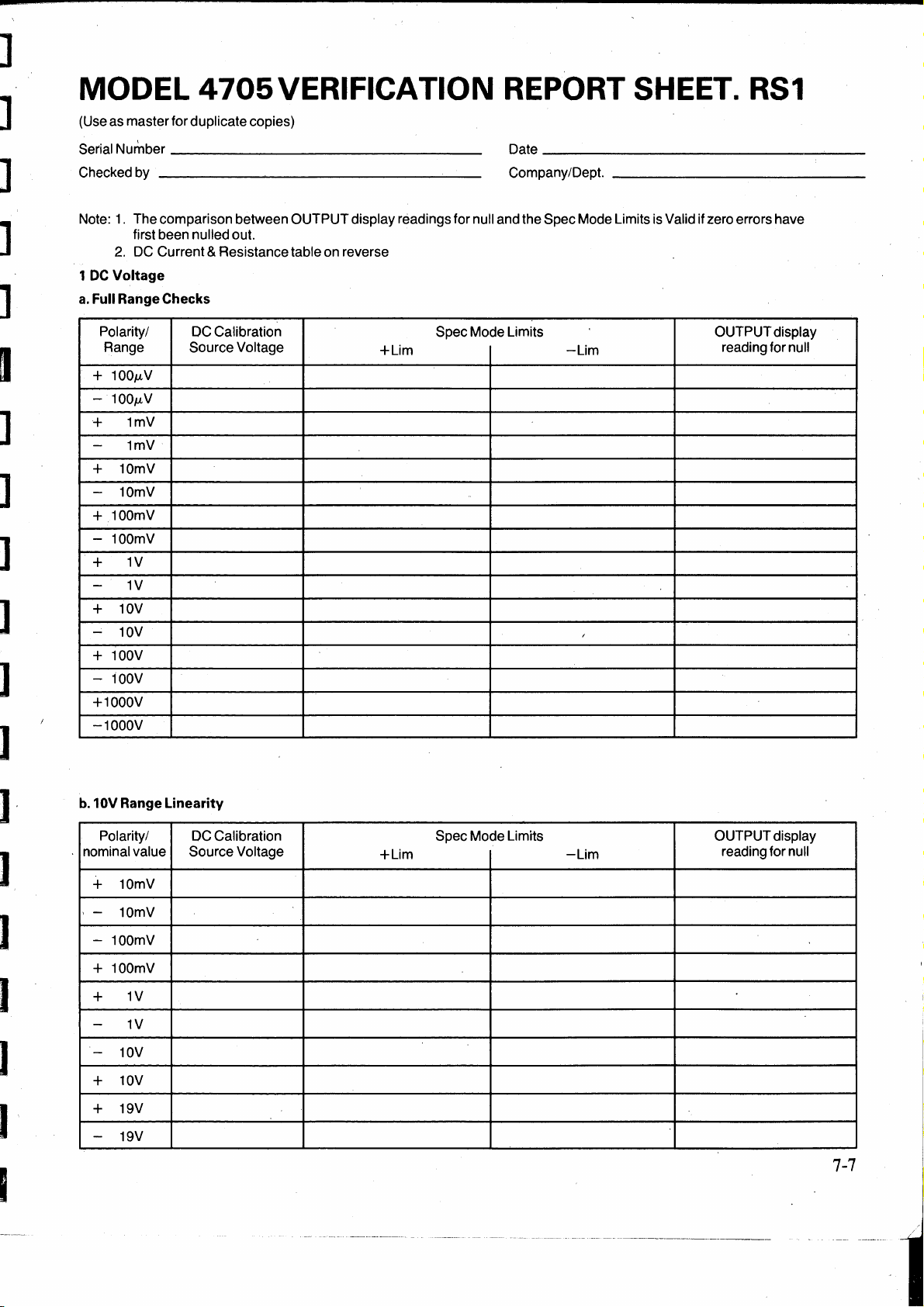
MODEL 4705VERIFICATION REPORT SHEET.
(Use as master for duplicate copies)
_______________
Serial Number
Checked by
________________
_
Date
Company/Dept.
_____________
RS1
__._
__
_
Note: 1 . The comparison between
1
a.
first been nulled out.
2.
DC Current & Resistance table on reverse
DC
Voltage
Full Range Checks
Polarity/ DC Calibration Spec Mode Limits OUTPUT display
Range
100µ.V
+
-
100µ.V
1mV
+
1mV
-
10mV
+
-
10mV
100mV
+
-
100mV
1V
+
-
1V
10V
+
-
10V
100V
+
-
100V
+1000V
-1000V
Source Voltage
OUTPUT
display readings for null and the Spec Mode Limits is Valid it zero errors have
+Lim
-Lim
,
reading for null
J
b.10V
Range Linearity
Polarity/
nominal value Source Voltage
10mV
+
-
10mV
-
100mV
100mV
+
1V
+
-
1V
-
10V
10V
+
19V
+
-
19V
DC Calibration Spec Mode Limits
+Lim
-Lim
OUTPUT display
reading for null
7-7
···-
--·---
-----------~----------
Page 87

2
DC
Current: Full Range Checks
Polarity/ Shunt
, Range
100µA
+
100µA
-
1mA
+
-
1mA
10mA
+
-
10mA
100mA
+
-
100mA
1A
+
-
1A
3 Resistance: Value Measurements
Range/Sense
100Mn Remote
LocalZero
10Mn
LocalZero
1MO
- LocalZero
1ookn
LocalZero
1okn
LocalZero
1kn
LocalZero
100n
LocalZero
i
:
10n
LocalZero
Value
Local
Remote
Local
Remote
Local
Remote
Local
Remote
Local
Remote
Local
Remote
Local
Remote
Local
DC
Calibration Spec Mode Limits OUTPUT display
Source Voltage
Specified
Current Used
1µA
1µA
10µA
100µA
100µA
1mA
10mA ·
10mA
+Lim
Method used
Current Displayed
Value
-Lim
___________________
SpecMode Measured
+Lim
-Lim
reading for
Value
nu11
·
_
7-8
Page 88

I
I
I
I
I
I
I
I
I
AC Specification Verification
Choice of Verification Method
The wide dynamic range of the 4705 makes it
necessary to employ diff erent verification methods
· for different groups of . output and frequency
ranges.
For
instance: The most common method of verifying
AC Voltage outputs is to check against an accurate
DC
Voltage Standard via a Thermal Transfer.
However, available thermal transfer standards are
not suitable for direct verification of the millivolt
ranges, because their transfer elements are
insufficiently sensitive.
Naturally, the range, accuracy and traceability of
users' standards governs the degree to which the
performance of any new equipment can be verified.
of
This is especially true for the 4705, in view
range of the parameters to be checked.
This section describes a recommended method of
verifying each ofthe parameters listed below. Where
appropriate, alternative methods are described in
. Appendices to the section.
Parameters to be Verified, with Recommended
Methods
The following list of parameters is grouped
according to the type of equipment suitable for
verification.
the
is
An alternative method
for users in possession
lO0kHz) Inductive Voltage Divider
3. Current Ranges (1mA to 1A).
a.
1 0mA, 1 00mA and 1 A Full Range values
are checked using a Thermal Transfer
Standard fitted with standard shunts at
and
HF,
against a
and
b.
The 1 mA Full Range value can be checked
using the same method, provided that lowcurrent shunts for the thermal transfer
standard are available.
Alternatively, if calibrated
available., the Current Ranges can be verified by
voltage measurement, using an
described in Appendix
Fixed or Adjustable Voltage Standard?
Many users who are able to verify
Current to the accuracy required for the 4705, will
also have access to an adjustable
as
Standard
be verified at cardinal values.
DC
Voltage Standards only, the 4705 can be
verified at non-cardinal values directly or by using
the 4 705 'Error Mode'. In both cases users will need
to calculate the effects
uncertainty, so calculations for total tolerance limits
are given in Appendix 4.
Reference.
described at Appendix 2
of
a ,Wideband (to
(WIVD).
DC
Current Standard.
AC
current shunts are
AC
DVM,
3.
AC
Voltage and
DC
Voltage
In
these cases their 4 705 can
For
users with fixed
of
their own Standards'
LF
as
1. Voltage Ranges
a.
Full Range values are verified at
by direct thermal transfer against a
Voltage Standard.
and
b.
Instrument Linearity
and 19.0000V on the lOV range at LF,
using the same method.
2. Millivolt Ranges
Full Range values are verified
a.
At LF:
Commercially available Inductive Voltage
Divider (IVD) -and standardized DVM
Transfer. (Such IVDs are normally only
suitable for
5kHz).
and
b.
at HF:
· A 100% to 10% of Range Transfer method,
after verifying 1 0V range
HF
1 V
standardized and corrected for linearity
error, then used as a transfer standard. The
method
(1
V to
1000V)
(1
mV to 1
LF
verification, up to about
Full Range value. A DVM
is
described later in this section.
is
verified
OOmV).
as
HF
LF
and
at 1 V,
follows:
linearity and
HF
DC
lOV
is
Summary of Equipment
Requirements
This summary relates to the recommended method
of verifying the 4 705. Alternative methods, with the
required equipment, are described in appendices.
AC VOL TAGE ( 1 V - 1 000V Full Range Values and
lOV Range Linearity)
An
Adjustable
accuracy.
Example:
Datron 4000 or 4000A Autocal Standard.
AC/DC
An
of operating over the range 1 V to
AC MILLIVOLTS
(lmV -l00mV
DC
Voltage Source of suitable
Thermal Transfer Standard capable
11
00V RMS.
Full Range Values)
7-9
Page 89

at
LF:
A commercially-available Inductive Voltage
1,
Divider tapped at 10:
suitable accuracy and frequency response.
100: 1 and 1000: 1
of
Transfer, and its displayed voltage is recorded and
checked against the, tol~rance limits. ·
See Appendix 1 for the procedure.
at HF:
The 4 705 under test with the correction figure for
10% of its 1 0V Range at
The
DC
Voltage Source used for 1 V - 1 000V
ranges.
and at both
The
AC/DC
1 000V ranges.
· . A D VM
response.
Example:
Datron 1081 or similar.
AC
CURRENT
DC
A
AC/DC
an
of Calibrated Thermal Transfer Current Shunts
_suitable
·
For
the alternative method at Appendix 3, a set
calibrated
and accuracy.
LF
and HF:
Thermal Transfer used for 1 V -
of
suitable accuracy and frequency
(lmA-
Current Source of suitable accuracy and
Thermal Transfer together with a set
accuracy.
AC
Current Shunts of suitable value
HF.
lA
Full Range Values)
of
of
Summary of Verification
Procedures
1. Full Range Voltage
Adjustable DC Standard
The 4 705
Range voltage · at
Thermal Transfer is nulled against the 4 705 Full ·
Range voltage. The
with the Thermal Transfer, and its output voltage
recorded. Its uncertainty
Tolerance Limits calculated. The
the
DC
Details of the procedure are on page 7-12.
Fixed DC Standard
The Thermal Transfer
Standard, and its fixed · voltage
Rep9rt Sheet. The 4705
this voltage, the
and the
output voltage
is
connected up and set to output a Full
voltage
Tolerance Limits are calculated. The 4705
is
within the tolerance limits.
S pec Mode tolerance
is
adjusted to null with the Thermal
(1V-
~e
required frequency. The
DC
Standard
is
OUTPUT display
1000V
is
adjusted to null
is
also recorded, and the
4705 is verified if
nulled · against _ the
is
recorded on the
is
Ranges)
DC
is
set to
recorded,
2. Linearity ( Performed
This should be checked at
in tum, or at user' s Reference standard voltages
close to the above values. Similar techniques are
used as for Full Range voltages.
results are recorded.
See page 7-12 or Appendix 1 for the procedure.
3. Full Range Voltage
Method 1
At
LF,
the 1 V Full Range value is first verified using
thermal transfer, then this voltage is divided via the
standard IVD to standardize an
millivolt Full Range value. The 4705 millivolt range
is
then verified at this standardized value by
measurement.
See page 7-13 for the procedure.
. .
At H
F,
the 4 705 is set to the 1 0V Range. Outputs are
measured at 1 0V and 1 V using thermal transfer, and
a linearity correction factor is calculated for the 1 V
output. . .
The 1 V Range is selected with output set to 1
HF.
at
correction factor and the output
standardize the
The 1 00m V Range is selected at
and the output measured on the DVM. The 1 00m V
Full Range value verifies if the
corrected value, plus or minus the specified
tolerances.
The
1 00m V Range, and used to verify
Range
verify the
See page 7-14 for the procedure.
Method 2
At
verified using thermal transfer, then this voltage is
divided via the wideband IVD to standardize an
DVM
millivolt range
value by
See Appendix 2 for the procedure.
The output setting
AC
DVM.
DVM
both
is
standardized again åt lOmV on the
in-
the same way. The process is
lmV
Range. ·
LF
and
HF,
the 1 V Full Range v~lue is first
at the millivolt Full Range value. The 4705
is
then verified at this standardized
D
VM
m~asurement.
on 1 OV
lV,
(1
mV
Range)
l0V
and 19.0000V
For
each check the
- 1
OOmV
AC
is
changed by the
HF
DVM
Ranges)
DVM
is
used to
Full Range,
reading is the
tp.e 1 Om
repe<:tted
at the
DVM
00m
V Full
to
AC
V
. '
I
[:
-77
C
~
C,.
JJ
__
,·
I
[
---
7-10
a
Page 90

4. Full Range Current
(us.ing
Standard Shunts)
The Thermal Transfer Current Shunt is fitted to the
of
Shunt lnput
the Thermal Transfer Standard and
the 4 705 set to output a Full Range current int~ the
shunt at the required frequency. The output current
is
split between the · shunt and the transfer element.
This is compared with the output from a Standard
DC
Current Source.
See Page 7-18 or Appendix 1 for the procedure.
Alternative M ethod
1
The 4 705 is connected up and set to output a Full
Range current into the calibrated
at the required frequency. The
AC
Current Shunt
4705 Current output
develops a voltage across the shunt which is
measured by the
,·
load the shunt.
The procedure is detailed in Appendix
AC DVM, with care taken not to
3.
·Specification Verification Procedures ·
Preparation
· Before attempting any verification ensure the following steps are carried out.
1.
Tum
on the instrument to be checked and allow a
of
minimum
2 hours to warm-up in the specified
environment.
2. Ensure familiarity with normal operation as
described in this Handbook.
Index of Recommended Procedures
( using adjustable
Voltage Ranges ( 1 V to 1 000V)
a.
Full Range Values
b.
Instrument Linearity ( 1
DC
Voltage Standard)
0V
Range)
Page
7-12
7-12
3. Cancel any
0
FF
and check that 'cal'
MODE
MODE
display.
Keys, ensure
is
(If
'cal'· is present,
OUTPUT
not present on the
tum
Calibration Keyswitch on the Rear Panel to its
RUN
4. Self-Test: select
described in Section
position).
Test
to carry out the test routine
4.
Terminate the test
routine.
·
'5:
Consult the manufacturer' s handbooks before
connecting and operating any equipment in the
measurement system.
6. Interconnections and Guarding: Refer to Section 4
page 4-1.
7. Select 24hr, 90dy or 1 yr on the
CALIBRA
TION
INTERVAL Switch. Refer to Section 4 page 4-10.
the
Millivolt Ranges ( 1 m V to 1
a.
LF
b.
HF
Current Ranges ( 1
Report Sheet
Alternative Procedures
As Recommended hut using Fixed
DC
Voltage Source ( with Report Sheet RS3) . 1
· Millivolt Checks using Wideband
Current Checks using Calibrated
Total Tolerance Limit Calculations
Uncertainty and Traceability
General Procedural Information
Harmonic Distortion Measurement
mA
RS2
00m
to 1 A)
V)
IVD
AC
7-13
7-14
7-18
7-19
Appendix
2
Shunts 3
4
5
6
7
7-11
Page 91

AC Voltage Verification Procedure
(U
sing Adjustable
Record Results on Report Sheet RS2 (page 7-19)
Full Range
DC
Checks
Voltage Calibration Standard)
(1
V - 1
OOOV)
,
r::::
:
[[
[:
I
DC
Voltage
Calibration
Standard
-----•~oc
I
I
WARNING
THE TERMINALS MARKED WITH THE -
SYMBOL CARRY THE OUTPUT OF THE
4705. THESE TERMINALS
OTHER CONNECTIONS
UNDER
VOLTAGES. UNDER NO CIRCUMSTANCES
SHOULD USERS TOUCH ANY OF THE
FRONT (OR REAR) PANEL TERMINALS
UNLESS THEY ARE FIRST SATISFIED
THAT NO DANGEROUS VOLTAGE IS
PRESENT.
a.
With
Standard to the Thermal Transfer
4-wire conriection and Remote Sense
available.
TEST COULD CARRY LETHAL
OUTPUT
OFF, connect the
AND
TO
THE LOAD
DC
DC
"-..
ANY
,Voltage
input. U
~~
se
if
Thermal
Transfer
Standard
...
·
I
AC....,.,..
___
_
4705to
Calibrated
be
I
j. Sum the Verification setup uncertainties . and
record in the U s column as voltage deviations.
(Refer to Appendix 5).
For Total Tolerance Limit Calculations refer to
Appendix 4 page 7-31, para
k.
Calculate the Lower and Upper Total Tolerance
Limits. Use Calculation A
calibrated by Datron.
Use Calculation B ifthe 4705 was last calibrated
against the standards being used for
verification.
1.
Each 4 705 Full Range output
Voltage outputs recorded in (g) are at or between
the corresponding Total Tolerance Limits.
1.
.
if the 4705 was last
is
verifiedif the
DC
[I
[
b.
With
OUTPUT
Thermal Transfer AC input. Use 4-wire
connection and Remote Sense.
c.
Configure the Thermal Transfer for
measurement at the required voltage.
d.
Set the 4705
Frequency (see Report Sheet RS2) . ·
e.
Set 4705
Transfer to the 4705 AC
f.
Configure the Thermal Transfer for
nulling.
g.
Configure the
required voltage, set its
its output to null the Thermal Transfer. Record its
output voltage on Report Sheet RS2.
h.
Repeat (
Sheet RS2 Table l(a).
7-12
OUTPUT
c)
OFF, connect the 4705 to the
OUTPUT
DC
to (g) for all 4 705 outputs on Report
Range, Voltage and ·
ON, ·and null the Thermal
OUTPUT.
Voltage Standard at the
OUTPUT
ON and adjust
AC
DC
Linearity
(l0V
Range)
m.If the
operations (
Tablel(b).
n.
Ifthe 1
Millivolt verification and
verification.
lOV Range verifi~d correctly, repeat
c)
to (g) for Report Sheet RS2
Vand
l0V
Ranges verified, proceed to
AC
AC
Current
Page 92
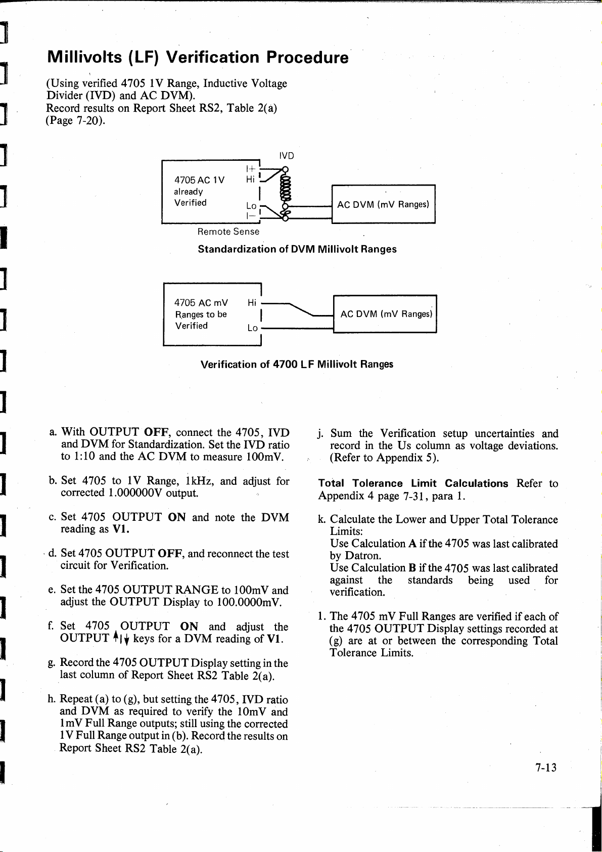
Millivolts (LF) Verification Procedure
I
(Using verified 4705 1 V Range, Inductive Voltage
Divider (IVD) and
Record results on Report Sheet RS2, Table 2(a)
(Page 7-20
).
AC
DVM).
a.
With
and
DVM
to
1:
10 and the
OUTPUT
4705AC
already
Verified
4705ACmV
R,anges
Verified Lo
OFF, connect the 4705, IVD
1V
Remote
Standardization
Verification
to
Sense
be
for Standardization. Set the IVD ratio
AC
DVM
to measure 100m
Hi
"j
of
,
of
-------,,
4700 L F
V.
----
DVM
~
AC
DVM
(mV
Ranges)
Millivolt
Millivolt
Ranges
AC
DVM
_______
Ranges
(mV
Rangesi
--J_
I
j. Sum the Verification setup uncertainties and
record
in
the U s column as voltage deviations.
(Refer to Appendix 5).
J
b.
Set 4 705 to 1 V Range, 1 kHz, and adjust for
corrected 1.000000V output.
c.
Set 4705
reading as
·
d.
Set 4705
OUTPUT
Vl.
OUTPUT
ON
and note the
OFF, and reconnect the test
circuit for Verification.
e.
Set the 4705
adjust the
f.
Set 4705
OUTPUT
g.
Record the 4705
_last
column
h.
Repeat ( a) to (g), hut setting the 4 705, IVD ratio
and D VM as required to verify the 1
OUTPUT
OUTPUT
OUTPUT
+
1,
keys for a
OUTPUT
of
Report Sheet RS2 Table 2(a).
RANGE
to lO0mV and
Display to 100.0000m
ON
and adjust the
DVM
reading
Display setting in the
Om
1 m V Full Range outputs; still using the corrected
1 V Full Range output in (b
).
Record the results on
Report Sheet RS2 Table 2(a).
DVM
V.
of
VI.
V and
Total Tolerance Limit Calculations Refer to
Appendix 4 page 7-31 , para
k.
Calculate the Lower and Upper Total Tolerance
1.
Limits:
Use Calculation A ifthe 4705 was last calibrated
by Datron.
Use Calculation
B ifthe 4705 was last calibrated
against the standards being used for
verification.
1.
The 4 705 m V Full Ranges are verified if each
the 4705
OUTPUT
Display settings recorded at
of
(g) are at or between the corresponding Total
Tolerance Limits.
7-13
Page 93

Millivol,ts (HF) Verification
Procedure
(Using verified 4705
Range Correction Factor and
results on Report Sheet RS2, Table 2(b) (Page 7-
20).
Full Range Checks
N.B. These verification checks,are not full traceable.
The verified output values
and
l0V
on the
4 705 linearity error at 1 V on the 1 0V range. From
the linearity measurement a 10%
and Scaling F actor
This fäctor
output setting at 10%
DVM
lnterconnections
PIG
is
subsequently used to correct the 4705
for verification
1 (lOV and 1 V Ranges)
AC
1 V and lOV Ranges, 10%
AC
DVM) Record
(1
mV
- 1 OOmV
of
1 V on the 1 V Range;
l0V
Range are used to measure the
'C'
is
derived.
of
r.ange,
of
the next range down.
at
1 OOkHz)
of
range Linearity
to standardize a
All
outputs
Remote
Local Guard
FIG 2 (l00mV
All
outputs at 1 MHz,
Local Guard
4705
Sense
to
4705
at
1 MHz ,
and
lmV
Ranges)
I
0.N/C
I
0N/C
600mm Uniradio
M70 (75a/67pF/m)
'
/
600mm Uniradio
'
M70 (75n/67pF/m)
1V
Range
Local Guard
4-wire
,100mV
Range
Local Guard
2-wire
7-14
Page 94

]
]
]
]
]
I
l
]
l
]
Stage 1 Derive the Linearity and Scaling Factor
as
follows: ( C
0.1):
a.
Ensure that the Millivolts (LF) Verification
has been completed.
Ensure- that the 4705 has been verified at
lOV
and 1 V HF(lO0kHz)Full Range (page
7-12
).
Record the measured values asfollows:
4705 lOV
Actual output voltage 4705 1 V
Actual output voltage - 'V2'
b.
Calculate 1 V correction 'V3' = 1
c.
With
OUTPUT
4705 terminals using the exact 4-wire
connections as_in Pig.
measure AC on its 1 V range.
d.
On 4705, select the 1 V range and Remote
Sense.
Set
FREQUENCY
Set O
UTPUT
Set
OUTPUT
reading
Set
as
OUTPUT
is
a number of value close to
FR
setting - 10.000,00V
'Vl'
FR
setting - 1.000,000V
OFF
connect a DVM to the
1.
Set the DVM to
to
lMHZ.
display reading to
ON, and note the DVM
'Vt'.
OFF.
V2
V3.
'C'
Record in 5 ½ digits resolution
Vl=
V2=
V3=
Vt
is
a transfer value
e.
On 4 705, select the
Sense).
Set 4705
Set
Adjust the
reading of Vt.
f.
Note the 4705
'V4'.
Set
g.
From the values
1 0V range linearity correction and scaling
factor
OUTPUT
OUTPUT
OUTPUT
OUTPUT
'C'
as
follows:
ON.
OUTPUT
OFF.
C
lOV
range (Remote
display reading to 1
display for a DVM
display reading
Vl
and
V4
calculate the
=
Vl x V4
100
V.
as
Vt=
Record in 5 ½ digits resolution
V4=
Calculate in 5 ½ digits resolution
c=
I
I
7-15
Page 95

L
Stage 2 To Verify the
Output
a.
Ensure that the
4705 terminals as shown
b. Set the 4705 to the 1 V
Calculate the value 'V3 x C'.
Set
OUTPUT
c.
Set the
d.
Set 4 705
settle. Note the
e.
Set4705
DVM
shown in Fig. 2.·
f.
Set 4705 to its lO0mV
(Remote Sense is automatically deselected.)
Set
Adjust the 4705 Output
ofV(lO0t).
setting as 'V(lO0m):
to the 4705 terminals in 2-wire as
OUTPUT
100mV
DVM
display to this value.
DVM
to measure lO0mV.
OUTPUT
DVM
OUTPUT
ON.
Notethe4705
AC Range Full Range
is still connected to the
in
Fig.
1.
AC
range.
ON,
allow the output to
reading as 'V(lO0t)'.
OFF
andreconnectthe
AC
range.
fora
DVM
OUTPUTdisplay
reading
Calculate in 5
I
V3xC=
V(l00t)
I
V(lO0t)=
Record in 5 ½ digits resolution
.1
V(I0Om) =
½ digits resolution
is a transfer value
L
[I
J
~
Il
[
i,
c-
Record this setting in the last column
table 2 (b).
Stage 3 To Verify the 1
Output
a.
Ensure that the
4 705 terminals as shown in Fig. 2.
b.
Ensure that the 4705
AC
range.
Calculate the value 'V( 1 00m) x C'.
Set
OUTPUT
c.
Set the
d.
Allow the output to settle.
Note the
e.
Set 4705 to its lOmV
Adjust the 4705 Output
ofV(l0t).
setting as 'V(lOm)'.
DVM
DVM
Note the 4705 OUTPUT display
Om
V AC Range Full Range
DVM
is still connected to the
is
set to the lO0mV
display to this value.
to measure lOmV.
reading as 'V( 1 0t)'.
AC
range.
fora
DVM
of
RS2
reading
Calculate in 5
V(lO0m) x
V(l0t)
V(l0t)
Record in
V(lOm) =
C=
is
=
4½
[:_
½ digits resolution
a transfer value
digits resolution
7-16
Record this setting in the last column
table 2(b).
of
RS2
a
Page 96

Stage 4 To Verify the 1
Output
a.
Ensure that the DVM is still connected to the
4705 terminals as shown in Fig.2.
mV
AC Range Full Range
Calculate in
4½
digits resolution
b.
Ensure that the 4705
is
set to the
range.
Calculate the value
OUTPUT
Set
c.
Set the DVM to measure lmV.
d.
Allow the output to settle.
'V(l0m)
display to this value.
x C'.
Note the DVM reading as 'V(lt)'.
e.
Set 4705 to its
Adjust the
lmV
AC range.
4705 Output to
give
DVM reading of V(lt).
Note the
4
705
OUTPUT
display setting
. 'V(lm)'.
Record this setting in the last column
table 2(b). ·
Stage 5 Verification Against Limits
For Total Tolerance Limit Calculations
Refer to Appendix 4 page
7-31
para
l0mV
1.
AC
a settled
as
of
RS2
V(lOm) x
V(lt)
V(lt) =
Record in
V(lm) =
C=
is
a transfer value
3 ½ digits resolution
a.
Sum the V erification setup uncertainties and
record in the Us column ofRS2 Table 2(b) as
voltage deviations. (Refer to Appendix 5).
b.
Calculate the Lower and Upper Total
Tolerance Limits:
Use Calculation A
if the 4705 was last
calibrated by Datron.
Use · Calculation B if the 4705 was last
calibrated against the standards being used
for verification .
.
c.
Each 4 705 m V Full Range (HF) is verified if
4705
the
OUTPUT display settings
V(lOm) and V(lm), recorded in the last
columnofRS2 Table2(b), are atorbetween
their corresponding Wideband Calculated
Tolerance Limits.
V(lOOm),
7-17
Page 97

AC Current Verification Procedure
(U
sing Thermal Transfer, Current Shunts and
Current Standard).
Record results on Report Sheet RS2, Table 3
(Page 7-20
).
DC
Full Range Checks
a.
With 4705
AC
and then I,
OUTPUT
Frequency
b.
Configure the Thermal Transfer for 1 0mA
Current measurement and connect the
appropriate shunt.
c.
With
I---:
terminals across the Shunt.
d.
Set 4705
Transfer to the 4705
Set 4705
e.
With
Standard for an output
across the Transfer Shunt.
f.
Set the
output current to null the Thermal Transfer.
Record its output current on Report Sheet RS2
Table3(a).
OUTPUT
of
OUTPUT
OUTPUT
OUTPUT
OUTPUT
DC
Standard
(1
mA - 1A)
4705 under
Verification
DC
Current
Calibration
Standard
OUTPUT
Display to 10.00000mA at a
300Hz.
OFF, connect the 4705 I+ and
OFF, configure the
AC~
-0-
DC!_/
OFF, set the Function to
RANGE
ON, and null the Thermal
AC
OUTPUT.
OFF.
of
1 0mA, and connect
OUTPUT
ON
to 10m,
DC
Current
and adjust its
Current
I
Transfer
Switch
I
I
--
Shuntlnput
with
Shunt Fitted
Thermal
Transfer
Standard
I
j.
If
the Thermal Transfer has been adequately
calibrated for 1 mA transfers, repeat ( a) to
4 705 1 mA Full Range outputs, recording the
Standard output currents in Report Sheet RS2
Table 3(b).
k.
Sum the Verification setup uncertainties and
record in the
(Refer to Appendix 5).
For Total Tolerance Limit Calculations
refer to Appendix 4 page
1.
Calculate the Lower and Upper Total
Tolerance Limits.
Use Calculation
by Datron.
Use Calculation
against the standards being used for
verification.
m.Each 4705 Full Range output verifies if the
Current outputs recorded in (
the corresponding Total Tolerance Limits.
U s column as current deviations.
7-31
Para
1.
A ifthe 4705 was last calibrated
B ifthe 4705 was last calibrated
f)
are at or between
(g)
for
DC
DC
g.
Set 4705 Frequency to 5kHz, and repeat (c)
to
(f).
h.
Repeat (a) to (g), but for 4705 lO0mA and
Full Range outputs.
7-18
lA
Page 98

MODEL
RS2
-For Users
Serial
Number
with
______________
4705
Adjustable
VERIFICATION REPORT SHEET. RS2
DC
Voltage Standards.
Date
Checkedby
Note: -On
1.
AC
a.
1Vto
OUTPUT
RANGE/
FREQUENCY Voltage
1V
1V
10V
10V 100kHz 10.0000V 9.9954
100V 1kHz
100V 100kHz
1000V
1000V
_____________
receipt of the instrument it
VOLTAGE (Using Adjustable
1000V Ranges.
4705
1kHz 1.00000V .99965 1.00035 0.00013V
100kHz 1.00000V .99954
1kHz 10.0000V 9.9965 10.0035
1kHz 1000.00V
30kHz 1000.00V
4705 Wideband
Nominal
OUTPUT
100.000V
100.000V
Lower(Lr) Upper(Ur)
(
99.965
99.954
999.65
999.54
_
Company/Dept.
is
recommended
DC
Voltage Standard via Thermal Transfer)
Relative Accuracy
Tolerance Limits Uncert'y Uncert'y
1.00046
10.0046 0.0115V
100.035 0.013V
100.046 0.020V
1000.35
1000.46 0.25V
to
checkat the frequencies
Datron User's Wideband Calculated Total
Cal.Std.
±Ud(Abs)
· 0.00115V
0.0013V
0.17V
Cal.Std.
±Us(Abs)
_________________
shown
below.
Tolerance Limits
Lower
Upper
User's
DCStandard
valuefor
Null
_
J
b.
Linearity (Performed
1kHz 1.0000V
10V
1kHz
10V
10V
10.oboov
1kHz 19.0000V
on 1 OV
0.9987
9.9965
18.0040
Range)
1.0013 0.00013V
10.0035 0.0013V
19.0060 0.0026V
J
7-19
Page 99

[
2.AC MILLIVOLTS
a.
LF 1 kHz
100mV
10mV
1mV
b.
HF
100mV 100.0000rriV 99.894
10mV 10.0000mV
1mV 1.0000mV .989
3.
AC
a.
10mA
(using Verified 1 V Full Range, lnductive Voltage Divider and
4705 4705 Wideband Datron User's Wideband Calculated Total
OUTPUT
RANGE
100.000mV
10.000mV 9.986
1.000mV
100kHz
(Using Verified 1 V and 1
CURRENT
to
1A
Ranges. (Using.Thermal Transfer, Current Shunts and
1mVto
Nominal Relative Accuracy
OUTPUT Tolerance Limits
Voltage
100mV
Lower(Lr) Upper(Ur)
99.953
.990
9.980
Ranges
100.047
10.014
1.010 0.010mV
OV
Full Range, 10% Range Correction and
100.106
10.020 0.017mV
1.011
AC
DVM)
Cal.Std. Cal.Std. Tolerance Limits
Uncert'y Uncert'y
±Ud(Abs)
0.035mV
0.013mV
0.067mV
0.012mV
±Us(Abs)
l..ower
AC
DC
Current Standard)
DVM)
Upper
4705
OUTPUT
Display
Setting,
4705
OUTPUT
RANGE,
F.REQUENCY
300Hz 9.9962 10.0038
10mA
10mA 5kHz 9.9949
100mA 300Hz
100mA 5kHz
1A 300Hz .99944 1.00056 0.00029A
1A 5kHz
b. 1 mA
Range. (It Thermal Transfer is calibrated at this level)
1mA 300Hz
1mA 5kHz
Transfer
Shunt Relative Accuracy Cal.Std.
Value Tolerance Limits Uncert'y Uncert'y
Wideband
Lower(Lr) Upper(Ur)
10.0051
99.962
99.949
'
.99925
.99962
.99949 1.00051 0.00026mA
100.038
100.051 0.026mA
1.00075 0.00044A
1.00038 · 0.00026mA
Datron
±Ud(Abs)
0.0026mA
0.0026mA
0.026mA
User's Wideband Calculated Total
Cal.Std.
±Us(Abs)
Tolerance Limits
Lower
Upper
User's
DC Standard
våluefor
Null
7-20
Page 100

Appendix 1 to:
4705 User's Handbook
Section 7
]I
APPENDIX
VERIFICATION
,flXED
DC VOLTAGE
1 ·
PROCEDURES FOR USERS
STANDARDS
AC Voltage Verification Procedure
(U
sing Fixed Voltage
Record results on,~eport Sheet RS3 (Page 7-25).
Full Range
Checks
DC
(1
V - 1
DC
Voltage
Cal
ibration
Standard
Calibration Standard).
OOOV)
I
•
DC
Thermal
Transfer
Standard
I
WARNING
THE TERMINALS
~
THE 4705. THESE TERMINALS
OTHER CONNECTIONS
UNDER
VOLTAGES.
SHOULD
FRONT (OR REAR) PANEL TERMINALS
UNLESS THEY ARE FIRST SATISFIED
THAT NO
PRESENT.
a.
· available.
b.
c.
d.
e.
SYMBOL CARRY THE OUTPUT
TEST COULD CARRY LETHAL
UNDER
USERS
DANGEROUS
With
OUTPUT
Standard to the Thermal Transfer
4-wire connection and Remote Sense if
With
OUTPUT
Thermal Transfer
connection and Remote Sense.
Configure the Thermal Transfer for
measurement at the required voltage.
Set the
voltage,
Transfer to its output.
Record its output voltage on Report Sheet RS3
Table
Voltage'.
Configure the Thermal Transfer for
measurement at the required voltage.
DC
Voltage Standard to the required
OUTPUT
l(a)
as '4705 Required
MARKED
NO CIRCUMSTANCES
TOUCH
OFF, connect the
OFF, connect the 4705 to the
AC
input. U se 4-wire
ON,
and null the Thermal
WITH THE
AND
TO
THE LOAD
ANY
VOLTAGE IS
OF
DC
DC
input. U se
OUTPUT
Voltage
OF
ANY
THE
DC
AC
f.
g.
h.
j;
k.
I.
Total Tolerance Limit Calculations
See Appendix 4 page
m.Calculate the Lower and Upper Total Tolerance
WITH
.
AC
I
...
4705
under
Verification
I
Set 4705
0
UTPUT
Transfer.
Record
Null' on Report Sheet RS3 Table l(a).
Ensure that the 4705 CALIBRATION
INTERV
Spec key and record the
in ppm as
canceL
Obtain the Datron Calibration Uncertainty from
Section
ppm'.
Repeat ( c) to
4705 outputs on Report Sheet RS3
Table l(a).
Sum the Verification setup uncertainties and
record as
(Refer to Appendix 5).
Limits.
Use Calculations A and C if the 4705 was last
calibrated by Datron.
se
Calculations B and C if the 4 705 was last
U
calibrated against the standards being used for
verification.
OUTPUT
Display reading to null on the Thermal
the'4705
AL
'±Ur
6 for the 4 705 output, and record
'+
OUTPUT
switch is set to 90dy. Press the 4705
ppm'. Press the S pec key again to
G)
for required voltages close to all
U s ppm'.
7-31
ON,
MODE
and adjust its
Display Reading for
Display reading
Para
2.
as'+
Ud
7-21
 Loading...