

DATREND Systems vPad-TI Operating Manual

™
vPad-TI
Transport Incubator Tester
Operating Manual
MN-120


vPad-TI
TM
Transport Incubator Tester
Operating Manual
© 2019 Datrend Systems Inc.
130-4020 Viking Way
Richmond, BC • CANADA • V6V 2L4
Tel: 800.667.6557 (North America Only) or
604.291.7747 • Fax 604.294.2355
e-mail: customerservice@datrend.com


This manual is Datrend P/N: 6100-126
Revision
A Initial Release 2019-Jan-24
Revision History
Description Date
Copyright
Datrend Systems Inc. (“DSI”) agrees to a limited copyright release that allows you to reproduce manuals and other
printed materials for use in service training programs and other technical publications. If you would like other
reproductions or distributions, submit a written request to Datrend Systems Inc.
Unpacking and Inspection
Follow standard receiving practices upon receipt of the instrument. Check the shipping carton for damage. If damage
is found, stop unpacking the instrument. Notify the freight carrier and ask for an agent to be present while the
instrument is unpacked. There are no special unpacking instructions, but be careful not to damage the instrument
when unpacking it. Inspect the instrument for physical damage such as bent or broken parts, dents, or scratches.
Claims
Our routine method of shipment is via common carrier. Upon delivery, if physical damage is found, retain all packing
materials in their original condition and contact the carrier immediately to file a claim. If the instrument is delivered in
good physical condition but does not operate within specifications, or if there are any other problems not caused by
shipping damage, please contact your local sales representative or Datrend Systems immediately.
Standard Terms and Conditions
Refunds & Credits
Please note only serialized products (products labelled with a distinct serial number) and accessories are eligible for
partial refund and/or credit. Non-serialized parts and accessory items (cables, carrying cases, auxiliary modules,
etc.) are not eligible for return or refund. In order to receive a partial refund/credit, the product must not have been
damaged, and must be returned complete (meaning all manuals, cables, accessories, etc.) within 90 days of original
purchase and in “as new” and resalable condition. The Return Procedure must be followed.
Return Procedure
Every product returned for refund/credit must be accompanied by a Return Material Authorization (RMA) number,
obtained from Datrend Customer Service. All items being returned must be sent prepaid (freight, duty, brokerage,
and taxes) to our factory location.
Restocking Charges
Products returned within 30 days of original purchase are subject to a minimum restocking fee of 15%. Products
returned in excess of 30 days after purchase, but prior to 90 days, are subject to a minimum restocking fee of 20%.
Additional charges for damage and/or missing parts and accessories will be applied to all returns. Products which
are not in “as new” and resalable condition, are not eligible for credit return and will be returned to the customer at
their expense.
Certification
This instrument was thoroughly tested and inspected and found to meet DSI’s manufacturing specifications when it
was shipped from the factory. Calibration measurements are traceable to the National Research Council of Canada
(NRC) and/or the National Institute of Standards and Technology (NIST). Devices for which there are no NRC/NIST
calibration standards are measured against in-house performance standards using accepted test procedures.

WARRANTY
Warranty and Product Support
Datrend Systems Inc. ("DSI") warrants this instrument to be free from defects in materials and workmanship under
normal use and service for one (1) year from the date of original purchase. This warranty will be automatically
extended to a maximum of two (2) years from the date of original purchase provided that calibration is performed
on an annual basis by a Datrend Authorized Service Center (refer to Chapter 7 of this manual). During the warranty
period DSI will, at our option, either repair or replace a product at no charge that proves to be defective; provided
you return the product (shipping, duty, brokerage and taxes prepaid) to DSI. Any and all transportation charges
incurred are the responsibility of the purchaser and are not included within this warranty. This warranty extends only
to the original purchaser and does not cover damage from abuse, neglect, accident or misuse or as the result of
service or modification by other than DSI. IN NO EVENT SHALL DATREND SYSTEMS INC. BE LIABLE FOR
CONSEQUENTIAL DAMAGES.
This warranty applies only to Datrend manufactured product and does not include OEM components which are
provided as part of a system. These OEM components include, but are not limited to netbook, laptop or desktop
computers, and these components shall be covered only by the OEM manufacturer’s limited warranty, and warranty
issues must be handled direct with the manufacturer.
No warranty shall apply when damage is caused by any of the following:
! Misuse or abuse of any form;
! Use of an AC power supply adapter other than the AC adapter specified for the instrument;
! Power failure, surges, or spikes;
! Damage in transit or when moving the instrument;
! Improper power supply such as low voltage, incorrect voltage, defective wiring or inadequate fuses;
! Accident, alteration, abuse or misuse of the instrument;
! Fire, water damage, theft, war, riot, hostility, acts of God, such as hurricanes, floods, etc.
Only serialized products (those items bearing a distinct serial number tag) and their accessory items are covered
under this warranty. PHYSICAL DAMAGE CAUSED BY MISUSE OR PHYSICAL ABUSE IS NOT COVERED
UNDER THE WARRANTY. Items such as cables and non-serialized modules are not covered under this warranty.
This warranty gives you specific legal rights and you may have other rights, which vary from province to province,
state to state, or country to country. This warranty is limited to repairing the instrument to DSI's specifications.
When you return an instrument to DSI for service, repair or calibration, we recommend shipment using the original
shipping foam and container. If the original packing materials are not available, we recommend the following guide
for repackaging:
! Use a double-walled carton of sufficient strength for the weight being shipped.
! Use heavy paper or cardboard to protect all instrument surfaces. Use non-abrasive material around all projecting
parts.
! Use at least four inches of tightly packed, industrial-approved, shock-absorbent material all around the instrument.
DSI will not be responsible for lost shipments or instruments received in damaged condition due to improper
packaging or handling. All warranty claim shipments must be made on a prepaid basis (freight, duty, brokerage, and
taxes). No returns will be accepted without a Return Materials Authorization ("RMA”) number. Please contact
Datrend Systems, 1(604)291-7747 or email customerservice@datrend.com to obtain a Return Materials
Authorization (RMA) number and receive help with shipping/customs documentation.
Re-calibration costs of instruments are not covered under the warranty.

Warranty Disclaimer
Should you elect to have your instrument serviced and/or calibrated by someone other than Datrend Systems,
please be advised that the original warranty covering your product becomes void when the tamper-resistant Quality
Seal is removed or broken without proper factory authorization. We strongly recommend, therefore, that you send
your instrument to Datrend Systems for service and calibration, especially during the original warranty period.
In all cases, breaking the tamper-resistant Quality Seal should be avoided at all cost, as this seal is the key to your
original instrument warranty. In the event that the seal must be broken to gain internal access to the instrument (e.g.,
in the case of a customer-installed firmware upgrade), you must first contact Datrend Systems. You will be required
to provide us with the serial number for your instrument as well as a valid reason for breaking the Quality Seal. You
should break this seal only after you have received factory authorization. Do not break the Quality Seal before you
have contacted us! Following these steps will help ensure that you will retain the original warranty on your instrument
without interruption.
WARNING
Unauthorized user modifications or application beyond the published specifications may result in electrical shock
hazards or improper operation. Datrend Systems will not be responsible for any injuries sustained due to
unauthorized equipment modifications.
DSI DISCLAIMS ALL OTHER WARRANTIES, EXPRESSED OR IMPLIED, INCLUDING ANY WARRANTY OF
MERCHANTABILITY OR FITNESS FOR A PARTICULAR PURPOSE OR APPLICATION.
THIS PRODUCT CONTAINS NO USER-SERVICEABLE COMPONENTS.
UNAUTHORIZED OPENING OF THE INSTRUMENT SHALL VOID THIS AND
ALL OTHER EXPRESSED OR IMPLIED WARRANTIES.
vPad™, vPad-XPORT™, vPad-ES™, vPad-353™, vPad-AS™, vPad-A3™, vPad-NFPA™, vPad-IN™, vPad-TI™,
vPad-RF™, vPad-Record Manager™, vPad-RM™ , vPad-EQM™, vPad-Check™, vPad-Cal™, and Datrend Docs™
and CMX™ are trademarks of Datrend Systems Inc.
Android
™
is trademark of Google Inc.


vPad-TI OPERATING MANUAL
Table of Contents
1Specifications ....................................................... 1
1.1 General ......................................................... 1
1.2 Data Collection Specifications ........................................ 2
1.3 Standard Accessories .............................................. 3
1.4 Optional Accessories ............................................... 3
2 General Information ................................................... 5
2.1 Overview ........................................................ 5
2.2 Features ........................................................ 6
2.3 Controls and Interface Connections ................................... 6
2.4 Setup .......................................................... 9
2.5 Power On....................................................... 13
2.6 vPad-TI Software ................................................. 13
2.7 Incubator ....................................................... 14
3 Tablet Setup ....................................................... 15
4Operation .......................................................... 17
4.1 HOME Screen ................................................... 17
4.2 Startup ......................................................... 19
4.3 Test Settings .................................................... 19
4.4 Global Settings .................................................. 20
4.5 Create/Edit/Run Autosequences ..................................... 24
4.6 Run Test ....................................................... 31
5 Running a Test ..................................................... 33
5.1 Overview ....................................................... 33
5.2 Noise Sound Level Test ........................................... 33
5.3 Probe Test ...................................................... 38
5.4 Air Flow/Air Velocity Test........................................... 42
5.5 Warm Up Time Test .............................................. 44
5.6 Cold Ambient Temperature at 36°C .................................. 47
5.7 Air Temperature Control Regulation Error(ACTRE) at 36 .................. 52
5.8 Air Temperature Control Test - High .................................. 54
5.9 Air Temperature Control Test - Low .................................. 57
5.10 Baby Temperature Control ........................................ 59
5.11 Humidity and Temperature Checks .................................. 61
5.12 Temperature Overshoot .......................................... 62
5.13 Alarm Sound Level - Inside ........................................ 65
5.14 Alarm Sound Level - Outside ....................................... 66
5.15 Saving Test Reports ............................................. 68
6 Test Reports ....................................................... 70
6.1 Overview ....................................................... 70
6.2 Recalling Records ................................................ 70
6.3 View Raw Data .................................................. 71
6.4 Exporting data .................................................. 72

vPad-TI OPERATING MANUAL
7 Calibration and Maintenance ........................................... 73

vPad-TI OPERATING MANUAL
Abbreviations, Definitions and Symbols
The following abbreviations, terms and acronyms are used throughout this manual:
ACTRE Air Control Temperature Regulation Error
AIT Average Incubator Temperature
ATX Average Temperature of Temperature Sensor X, where X = 2 - 5
AV Air Velocity
BSL Background Sound Level
°C degrees Celsius (centigrade)
°F degrees Fahrenheit
Autosequence A series of measurements or test operations that are run
automatically in a predefined order, with or without user involvement.
DUT Device Under Test
GUI Graphical User Interface
IT Incubator Temperature
IIT Independent Incubator Temperature
NSL Noise Sound Level
STC Steady Temperature Condition
STS Skin Temperature Sensor
TC Temperature Control
TEMP Temperature
WT Warm Up Time
CAUTION: Read the instructions for use before operating this device.
Definitions:
Some of the following definitions are paraphrased from the relevant sections and
clauses of IEC 60601-2-20, Edition 2
Air Control
Temperature
Regulation Error
Average Transport
Incubator
Temperature
Clause 201.12.1.106: an incubator operating in AIR
TEMPERATURE CONTROL shall have an AVERAGE
TEMPERATURE that does not differ from the CONTROL
TEMPERATURE of 36°C by more than ±1.5°C at an ambient
temperature between 20°C and 25°C; or, ±2°C at an ambient
temperature between 10°C and 20°C
Clause 201.3.203: the average of the maximum and minimum
INCUBATOR TEMPERATURES achieved during STEADY
TEMPERATURE CONDITION

vPad-TI OPERATING MANUAL
Average
Temperature
Clause 201.3.202: the average of the maximum and minimum
temperatures at any specified point in the COMPARTMENT
achieved during STEADY TEMPERATURE CONDITION
Compartment Clause 201.3.205: environmentally controlled portion of the
INCUBATOR intended to contain a baby
Control
Temperature
Clause 201.3.206: temperature selected on the incubator as the
desired temperature in the COMPARTMENT
Autosequence A series of measurements or test operations that are run
automatically in a predefined order, with or without user
involvement
Device Under Test The device (the transport incubator) being tested by VPad-TI
Graphical User
Interface
A display system for the test instrument (vPad-TI) which relies
on graphics to a large extent to display information. In the case
of vPad-TI, this is an Android tablet (10") with and Android type
operating system (5.1.1), or equivalent
Incubator Clause 201.3.205: an enclosure, intended to contain a baby and
having transparent section(s) which allow(s) for viewing of the
baby, provided with means to control the environment of the
baby primarily by heated air within the enclosure
Transport Incubator
Temperature
Independent
Incubator
Temperature
Clause 201.3.212: temperature of the air at a point 10 cm above
the center of the mattress surface in the COMPARTMENT
A temperature representative of INCUBATOR TEMPERATURE
provided by an independent indicator (not powered by the
incubator). Commonly an alcohol based thermometer (nonmercury), but may be of an alternate type)
NSL Noise Sound Level
Steady Temperature
Condition
Clause 201.3.211: the condition reached when the
INCUBATOR TEMPERATURE does not vary by more than 1
over a period of one hour
Skin Temperature
Sensor
Clause 201.3.210: a sensing device intended to measure the
baby’s SKIN TEMPERATURE
o
C

vPad-TI OPERATING MANUAL
1 Specifications
1.1 General Specifications
Environment:
• 15 °C to 40 °C (59 °F to 104 °F)
• 10% to 90% Relative Humidity
• Indoor Use Only
• Category II
• Pollution Degree 2
Note: Mains supply voltage fluctuations not to exceed +/- 10% of the nominal supply voltage.
User Interface:
vPad-TI is supplied with a 10" (nominal) Android tablet which has the vPad-TI application
pre-installed and ready to run. The software is controlled by touching a function button on
the graphical user interface (GUI) or, where applicable, by entering specific data via the
keyboard.
Display (10" Android Tablet):
1920 x 1200 color IPS touch screen LCD
Specifications/Chapter 1 # Page 1

vPad-TI OPERATING MANUAL
1.2 Data Collection Specifications
Temperature:
• Measurement Range: 25 °C - 50 °C
• Accuracy: Ta: ± 0.05 °C
• Resolution: 0.01 °C
• Convection: 5 ‘puck’ sensors (T6 - T10) - radiant warmer
• Air Conduction: 5 sensors (alternate ‘post’ Ta - Te) - incubator
1 mattress temperature
• Optional Skin Sensor
‘oven’ with thermal pad
contact:
Airflow:
• Measurement Range: 0.1 to 1 m/s
• Accuracy: ± 0.1 m/s
Relative Humidity:
• Measurement Range: 0 - 100%
• Accuracy: ± 3 %
• Resolution: 0.1% RH
Sound Level:
• Measurement Range: 30 dbA to 100 dbA, Type III
28 °C to 40 °C in 2 °C increments ± 0.01 °C resolution,
± 0.05 °C Accuracy
at 50% RH ± 15%
Non Condensing
• Accuracy: ± 3 dbA
• Resolution: 0.1 dbA
Data Retention:
• Capacity: up to 48 hours per test
• Sample Rate: 1/min or 1/sec, depending on parameter
Specifications/Chapter 1 # Page 2

vPad-TI OPERATING MANUAL
1.3 Standard Accessories
AC Adapter (all models): 100-240 VAC 50/60 Hz to 9 VDC (p/n 3000-611)
Blade Sets kit for P/N 3000-611: P/N 7500-490
(Includes: North America; Europe/Schuko; United Kingdom; China/Australia)
AA Battery, 1.2V 2300mAH: P/N 3310-012
1.4 Optional Accessories
For a complete list of available accessories, visit www.datrend.com or contact Datrend
Customer Service (see Chapter 7 for contact details)
Specifications/Chapter 1 # Page 3

vPad-TI OPERATING MANUAL
Specifications/Chapter 1 # Page 4

vPad-TI OPERATING MANUAL
2 General Information
2.1 Overview
vPad-TI is a portable data logging system for temperature, air flow, humidity, and sound level;
specifically configured to test infant transport incubators and, optionally, incubators and radiant
warmers to applicable IEC performance standards. The data collection system is designed to
operate for up to 48 hours from a rechargeable 4.8VDC nickel-metal hydride (4 AA cells)
battery, or alternatively, from a 5VDC switch mode AC adapter. The sensors and the data
collection system are placed on the mattress of the transport incubator, and external to the device
under test (DUT), a user interface based on an Android tablet communicates wirelessly to the
sensor system via Bluetooth, and provides the user with the ability to control the test operation
and display the results without disturbing the test environment.
vPad-TI incorporates all the functionality necessary to meet the requirements of the IEC
standard, related to temperature, airflow, humidity, and sound level tests. vPad-TI incorporates a
graphical user interface which interfaces wirelessly to 6 temperature sensors, 1 airflow sensor, 1
humidity sensor, and 1 sound level meter. vPad-TI also incorporates a non-volatile memory or "data
log" which is used to save test data, such tests typically being conducted by the user over several
hours or days.
Overview/Chapter 2 # Page 5

vPad-TI OPERATING MANUAL
2.2 Features
IEC 60601-2-20 ed.21 is a standard which specifies safety and performance requirements for an
infant transport incubator. Some of the parameters that lend themselves to testing are
temperature, sound level, air flow and humidity. These parameters are monitored at specific
locations within the incubator and are expected to conform to the values defined by the
Standard. vPad-TI provides the mechanical framework to hold the sensors in the appropriate
locations, and provides the ability to adjust the framework to fit incubators of various sizes.
vPad-TI provides 5 temperature sensors which are positioned according to the standard, with
one central sensor and one sensor in the center of each of four quadrants on the mattress. The
central sensor is an integral component of the data collection and wireless communication hub
of the system. In addition to the 5 temperature sensors, vPad-TI provides mattress
temperature, airflow, sound level and humidity sensors in separate packages which connect to
the central hub. The test protocols are designed to perform all the temperature tests in one
contiguous time block to avoid numerous long heating and cooling cycles. Tests of airflow,
sound and/or humidity are performed either before or after the temperature tests so that the
sensors can be moved about in the incubator without disrupting a temperature test.
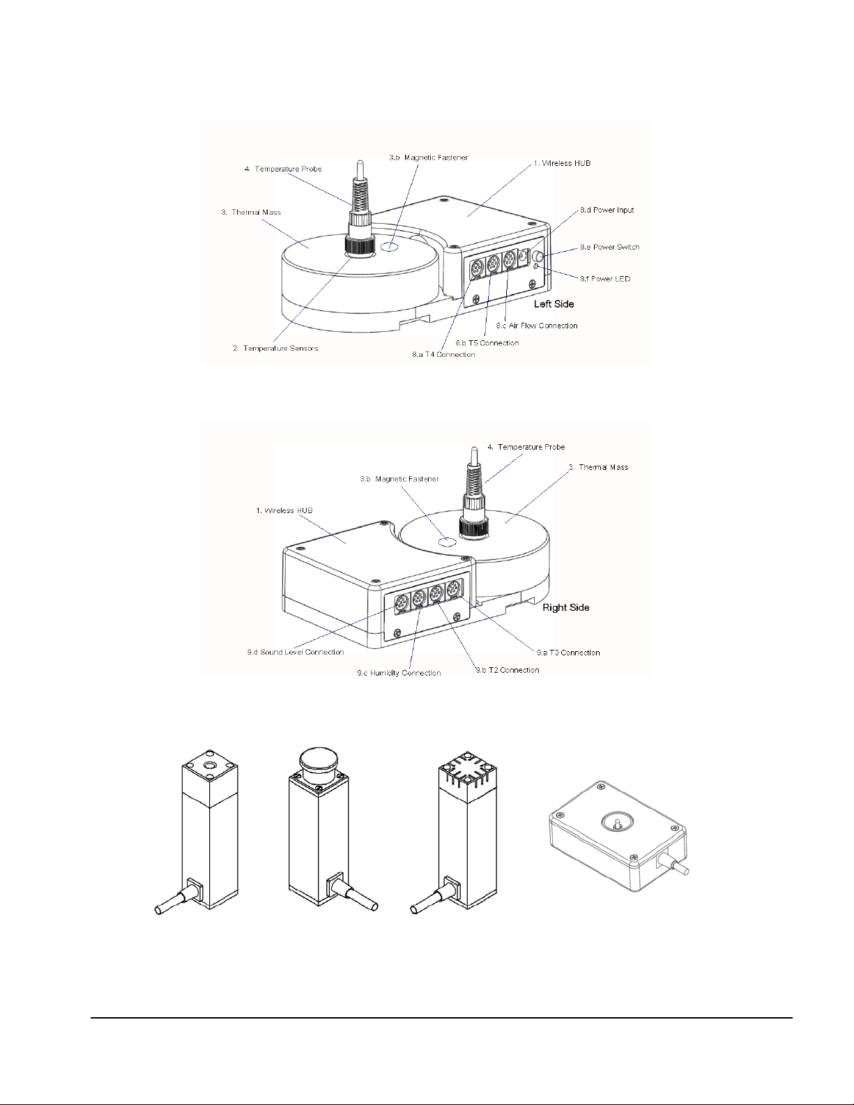
2.3 Controls and Interface Connections
Referring to Figure 1 through Figure 5, the following components, controls and interfaces of
the vPad-TI Transport Incubator Test system are:
1. Sensor Electronics and Wireless
Hub (the HUB)
2. Temperature Connectors Temperature Probes (Ta - Te) are connected on
3. Thermal Mass (the Puck)
4. Temperature Probe (Ta - Te) Bypasses the thermistor in the Puck and places the
Provides the connection point for all sensors used
internally to the incubator or warmer under test.
Also referred to as the DAT unit.
the top of a large, black thermal mass (Puck) to
place the thermistor in the correct position above
the mattress.
Thermal mass to mimic the infant body for
convection warming in a radiant warmer. Contains
Magnetic Fastener (3.b) for attachment of other
sensors
thermistor at the correct position above the
mattress, per the Standard.
1
Throughout this manual, IEC 60601-2-20 ed.2 is referred to as the “Standard”
Overview/Chapter 2 # Page 6

vPad-TI OPERATING MANUAL
5. Mattress Temperature Measures the temperature of the mattress
6. Airflow Sensor Measures the flow of air, and can be moved as
required. Held in place on the Puck magnetically.
7. Sound Level Sensor Measures sound level. Can be moved within the
device under test (DUT) and can also be connected
to an extension cable for external sound/alarm
level measurements. Held in place on the Puck
magnetically.
8. Humidity Sensor Measures Humidity. Can be moved within the
device under test (DUT). Held in place on the
Puck magnetically.
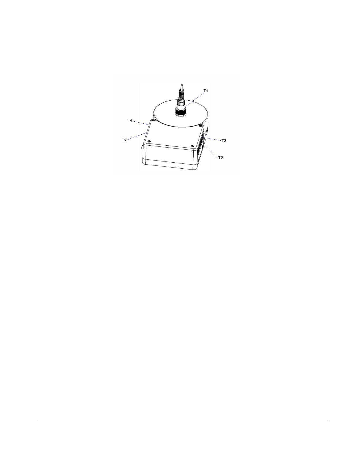
9. Hub Connections - Left Side a. T4 (Td) Temperature Input
b. T5 (Te)Temperature Input
c. Airflow Sensor Input
d. Power Input
e. Power LED
f. Power Switch
10. Hub Connections - Right Side a. T3 (Tc)Temperature Input
b. T2 (Tb)Temperature Input
c. Humidity Sensor Input
d. Sound Level Sensor Input
11. Positioning Frame Allows Tb - Te Pucks to be positioned with respect
to Ta at the center of the mattress
12. Positioning Frame Components a. longitudinal positioning bar
b. horizontal positioning bar
c. T bracket
Each of the sensors has an internal magnet on the bottom which will hold it in place on the
Thermal Mass. Each sensor also has a cable with a miniDIN connection to connect to the
HUB.
When used, the
Mattress Temperature sensor connects to the HUB in the Humidity
position, and the Humidity Sensor connects to the Mattress Temperature module in a daisy
chain fashion.
Overview/Chapter 2 # Page 7
vPad-TI OPERATING MANUAL
Figure 1: Wireless HUB - Left Side View
Figure 2: Wireless HUB - Right Side View
Figure 3:
Sound Level Sensor
Figure 4:
Air Flow Sensor
Overview/Chapter 2 # Page 8
Figure 5:
Humidity Sensor
Figure 6: Mattress
Temperature Sensor
vPad-TI OPERATING MANUAL
2.4 Setup
To test a transport incubator according to the Standard, the Sensor System must be placed on
the mattress of the DUT with the Temperature Probe of the Hub in the center of the mattress,
and the Temperature Probes of the remaining 4 Temperature Pucks placed in the center of
each of the 4 quadrants of the mattress. The positioning frame is designed to assist in the
positioning of the Pucks and to hold them in place during a test.
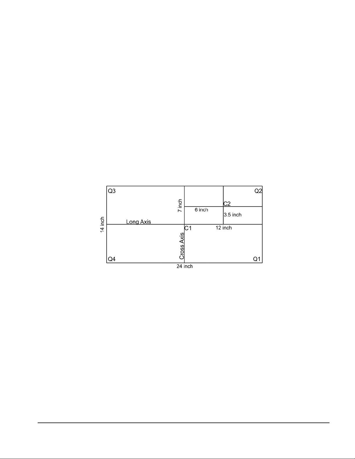
Measure the mattress to determine its size. For instance, the AirShields C200 has a nominal
mattress size of 14 inches wide (36 cm) by 24 inches long (61 cm). Divide the mattress into 4
quadrants, each quadrant being 7 inches (18 cm) by 12 inches (30.5 cm). For this mattress, the
center of quadrant Q2 is 3.5 inches above the long axis and 7 inches from the cross axis, see
point C2, Figure 7.
Figure 7: Mattress Quadrants and Center Locations
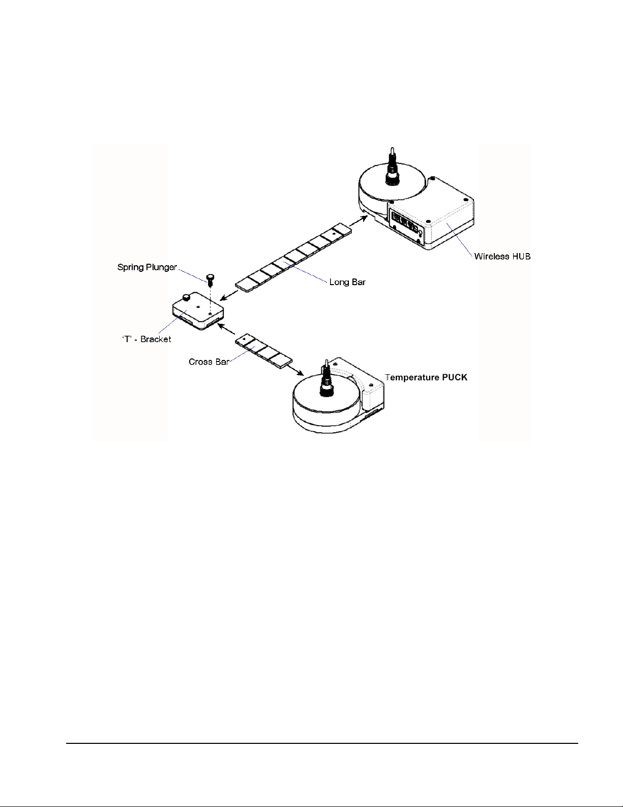
In setting up the positioning frame, the longitudinal (long) bar would be placed in the body of
the HUB, with the end having a small hole about 1" from the end sliding into the slot in the
HUB, as indicated in Figure 8. The ‘T- bracket’ is placed over the long bar and slid into the
position marked ‘6’ inches on the long bar. Similarly, the horizontal (cross) bar is slid into the
‘T- bracket’ and locked in place with the spring plunger. The smaller Temperature Puck is
then slid into place to the position marked ‘3.5’ inches on the cross bar. If the positioning
frame is placed with the temperature probe of the HUB in the center of the mattress at C1,
then the second temperature probe would be in the center of the mattress quadrant Q2 at
position C2 in the diagram. For mattresses of other sizes, the ‘small’ Pucks can be moved
along the bars as required to meet the dimensional requirements.
Overview/Chapter 2 # Page 9
vPad-TI OPERATING MANUAL
If the smaller Temperature Puck seems too close, it can be rotated 180 degrees, in which
case, add 3.5" to the markings on the long bar. In the example above, the 9.5 inch marking (6"
+ 3.5" = 9.5") would be used.
Figure 8: Positioning Frame Assembly
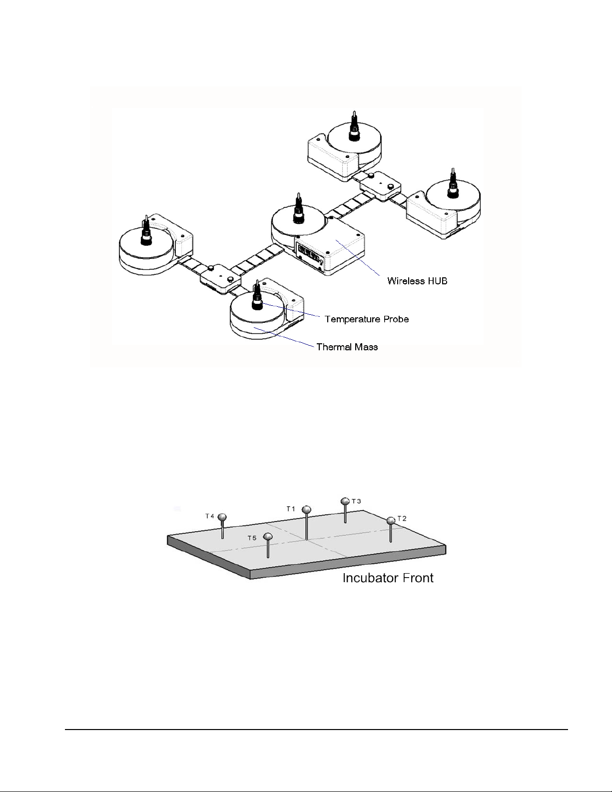
Temperature Pucks for each of the other three quadrants are set up in the same manner. The
fully assembled system is shown in Figure 9Figure 9.
The vPad-TI Transport Incubator test system is now configured mechanically, according to the
Standard, to take temperature and other measurements in the center of the incubator and in the
center of each of the four quadrants of the mattress. It is now necessary to make the electrical
connections for each of the sensors.
As previously described, the large round ‘Puck’ represents a thermal mass imitating the infant
body in a convection warming environment. This ‘Puck’ is made of aluminum with a black
heat absorbing coating, with a temperature sensor embedded in the aluminum block. In this
configuration, the temperature measured by the ‘Puck’ is specifically configured to test
warmers
. For testing
incubators
, a Temperature Probe is inserted into the connector at the
radiant
center of each Puck. This Temperature Probe bypasses the thermistor in the Puck and elevates
the thermistor in the Probe to a position approximately 10 cm above the mattress, in
accordance with the Standard.
Overview/Chapter 2 # Page 10
vPad-TI OPERATING MANUAL
Figure 9: Sensor Frame Fully Assembled
In the Test Reports generated by the test software, the temperatures are referred to as Ta (1) for
the center of the incubator, and Tb (2), Tc (3), Td (4) and Te (5) for each of the quadrants as
shown in Figure 10.
Figure 10: Temperature Sensor Positions
Overview/Chapter 2 # Page 11
vPad-TI OPERATING MANUAL
The cables from the individual Pucks will connect to the HUB as indicated in Figure 11,
Figure 1 and Figure 2.
Figure 11: Temperature Sensor Connection Locations
The sensors for Sound, Airflow and Humidity also connect to the HUB, as indicated in Figure
1 and Figure 2. These sensors are utilized when the relevant test is selected in the software test
setup. When utilized, the sensors are held in place on the Puck by magnets.
The tablet connects wirelessly via Bluetooth to the wireless HUB.
The tablet also provides connection to the Skin Sensor Oven through the USB port so
that Skin Temperature Probes can be checked for accuracy.
Overview/Chapter 2 # Page 12

vPad-TI OPERATING MANUAL
2.5 Power On
After the System has been setup for the required mechanical positions, it may be turned on by
pressing the Power On switch on the HUB, shown in Figure 1. If the HUB is being charged,
with the AC Adapter plugged into the Power Input connector, a small LED below the Power
On switch will illuminate RED, regardless of the position of the Power On switch. If the
Power On switch is activated but the AC Adapter is not plugged in, the LED will illuminate
YELLOW. If the AC Adapter is not plugged in and the Power On switch is NOT activated,
the LED will not illuminate.
The HUB may be powered by battery or by AC Adapter.
Once turned ON, the HUB will wait for the tablet to initiate communications.
2.6 vPad-TI Software
The vPad-TI software is pre-loaded on the tablet. When turned on, the tablet presents the
Android Home screen, where selecting the vPad-TI icon will run the vPad-TI Application.
When you exit the Application, the tablet will return to the Home screen. It is recommended
no other apps be loaded onto the tablet so as to avoid conflicts with other apps, or accidentally
infecting the computer with a virus or other malware. Problems which arise from loading other
apps on the tablet are not covered by warranty.
NOTE: The vPad-TI software is setup to test Infant Transport Incubators. The large
black PUCKs are the required thermal mass for Radiant Warmer testing and have
embedded temperature sensors for that purpose. The vPad-RW app is available for
Radiant Warmer testing.
The software will allow the user to create different test protocols that may not encompass the
complete requirements of the Standard, but which are suitable for testing or verifying different
parts of the incubator’s operation. The Default test protocol includes all of the tests required
by Section 8 (Accuracy of Data) and some parts of Section 11(Additional Requirements) of the
Standard. User defined protocols may be created, saved and recalled for future use.
In addition, the user can create a mini database of the incubators and warmers that have been
or are to be tested. In order to do a test, the user must input an identification number (ID)
and/or a serial number, so that the test report can be identified. The test technician’s initials
are also required so the report will show who was responsible for doing the test. Other
information can be optionally input to further identify the DUT.
Overview/Chapter 2 # Page 13

vPad-TI OPERATING MANUAL
2.7 Incubator Primer
Infant Incubators are a controlled temperature environment which are used to maintain the
body temperature of newborns who, for various reasons, are unable to regulate their own body
temperature. Incubators generally work in one of two modes: 1) air temperature control, or 2)
body temperature control.
In air temperature control, the heater in the incubator is used to control the temperature of the
air at a location close to the heater. The air is forced to flow through the incubator chamber by
means of a fan. The air circulates through the main chamber of the incubator where the infant
lies on a mattress. The air returns to the heating chamber, which normally is located in a
mechanical structure below the main chamber. The incubator is designed to create an airflow
which is reasonably consistent in the main chamber, normally from back to front. In addition,
the main chamber is designed to reduce temperature loss as much as possible through the use
of double walls of acrylic.
In many circumstances, keeping the infant surrounded by a blanket of air at a constant
temperature is sufficient to keep the infant warm. However, under certain circumstances the
infant may continue to lose heat. In these cases it may be more effective to control the
temperature of the air by monitoring the baby skin temperature directly and adjusting the air
temperature to maintain the skin temperature at the desired temperature. When operating in
this mode, the incubator will generally have an air temperature slightly above the skin
temperature of the infant.
In addition to controlling the temperature of the air, incubators will also support a number of
other features, including but not limited to: alarms for high temperature, humidity control and
independent, non-electronic, temperature indicators.
Overview/Chapter 2 # Page 14
 Loading...