

DATREND Systems Phase 3 Operating Manual

Phase 3
De fib rillato r and Transc utaneous Pac e m aker Analyze r
Operating Manual


Phase 3
Defibrillator and Transcutaneous Pacemaker Analyzer
Operating Manual
© 2007-2009 Datrend Systems Inc.
Unit #1 - 3531 Jacombs Road
Richmond, BC • CANADA. • V6V 1Z8
Tel: 800.667.6557 (North America Only) or
604.291.7747 • Fax 604.294.2355
e-mail: customerservice@datrend.com
This device is intended to be used only by
qualified Biomedical Electronics Technicians,
Technologists or Engineers, properly trained in
the operation, theory and service of
defibrillators


To order this manual, use Part Number 6100-440
Revision
Revision History
Description Date
G
- 5 Year Warranty
- Specify Mains Fluctuation
2009-June-24
Copyright
Datrend Systems Inc. (“DSI”) agrees to a limited copyright release that allows you to reproduce manuals and other
printed materials for use in service training programs and other technical publications. If you would like other
reproductions or distributions, submit a written request to Datrend Systems Inc.
Unpacking and Inspection
Follow standard receiving practices upon receipt of the instrum ent. Check the shipping carton for dam age. If
damage is found, stop unpack ing the instrument. Notify the freight carrier and ask for an agent to be present while
the instrument is unpacked. There are no special unpacking instructions, but be careful not to damage the
instrument when unpacking it. Inspect the instrument for physical damage such as bent or broken parts, dents, or
scratches.
Claims
Our routine method of shipment is via common carrier. Upon delivery, if physical damage is found, retain all packing
materials in their original condition and contact the carrier im mediately to file a claim.
If the instrument is delivered in good physical condition but does not operate within specifications, or if there are any
other problems not caused by shipping dam age, please contact your local sales representative or DSI imm ediately.
Standard Terms and Conditions
Refunds & Credits
Please note only serialized products (products labelled with a distinct serial number) and accessories are eligible for
partial refund and/or credit. Non-serialized parts and accessory items (cables, carrying cases, auxiliary modules,
etc.) are not eligible for return or refund. In order to receive a partial refund/credit, the product must not have been
damaged, and must be returned complete (meaning all manuals, cables, accessories, etc.) within 90 days of original
purchase and in “as new” and resalable condition. The Return Procedure must be followed.
Return Procedure
Every product returned for refund/credit must be accompanied by a Return Material Authorization (RMA) number,
obtained from Datrend Customer Service. All items being returned must be sent prepaid (freight, duty, brokerage,
and taxes) to our factory location.
Restocking Charges
Products returned within 30 days of original purchase are subject to a minimum restocking fee of 15%. Products
returned in excess of 30 days after purchase, but prior to 90 days, are subject to a minimum restocking fee of 20%.
Additional charges for damage and/or missing parts and accessories will be applied to all returns. Products which
are not in “as new” and resalable condition, are not eligible for credit return and will be returned to the customer at
their expense.
Certification
This instrument was thoroughly tested and inspected and found to m eet DSI’s manufacturing specifications when it
was shipped from the factory. Calibration measurements are traceable to the National Research Council of Canada
(NRC) and/or the National Institute of Standards and Technology (NIST). Devices for which there are no NRC/NIST
calibration standards are measured against in-house performance standards using accepted test procedures.
Page i

Warranty
Warranty and Product Support
Datrend Systems Inc. ("DSI") warrants this instrument to be free from defects in materials and workmanship under
normal use and service for five (5) years from the date of original purchase, subject to the exemptions listed below,
providing the instrument is calibrated in accordance with Chapter 7 of this manual. During the warranty period DSI
will, at our option, either repair or replace a product at no charge that proves to be defective; provided you return the
product (shipping, duty, brokerage and taxes prepaid) to DSI. Any and all transportation charges incurred are the
responsibility of the purchaser and are not included within this warranty. This warranty extends only to the original
purchaser and does not cover damage from abuse, neglect, accident or misuse or as the result of service or
modification by other than DSI. IN NO EVENT SHALL DATREND SYSTEMS INC. BE LIABLE FOR
CONSEQUENTIAL DAMAGES.
The following components are only covered for a period of two (2) years:
!NiCad Battery Pack
!Power Resistors
No warranty shall apply when damage is caused by any of the following:
!Discharge of a defibrillator into any terminal, interface connection or port, other than the specified Defibrillator
Input terminals of the instrum ent,
!Discharge of a transcutaneous pacemaker into any terminal, interface connection or port, other than the specified
Pacer Input term inals of the instrument,
!Use of an AC power supply adapter other than the AC adapter supplied with the instrument,
!Power failure, surges, or spikes,
!Dam age in transit or when m oving the instrument,
!Improper power supply such as low voltage, incorrect voltage, defective wiring or inadequate fuses,
!Accident, alteration, abuse or m isuse of the instrum ent,
!Fire, water damage, theft, war, riot, hostility, acts of God, such as hurricanes, floods, etc.
Only serialized products (those items bearing a distinct serial number tag) and their accessory items are covered
under this warranty. PHYSICAL DAMAGE CAUSED BY MISUSE OR PHYSICAL ABUSE IS NOT COVERED
UNDER THE W ARRAN TY. Items such as cables and non-serialized modules are not covered under this warranty.
This warranty gives you specific legal rights and you may have other rights, which vary from province to province,
state to state, or country to country. This warranty is limited to repairing the instrument to DSI's specifications.
When you return an instrument to DSI for service, repair or calibration, we recommend shipment using the original
shipping foam and container. If the original packing materials are not available, we recommend the following guide
for repackaging:
!Use a double-walled carton of sufficient strength for the weight being shipped.
!Use heavy paper or cardboard to protect all instrument surfaces. Use nonabrasive material around all projecting
parts.
!Use at least four inches of tightly packed, industrial-approved, shock-absorbent material all around the
instrum ent.
DSI will not be responsible for lost shipments or instruments received in damaged condition due to improper
packaging or handling. All warranty claim shipments must be made on a prepaid basis (freight, duty, brokerage, and
taxes). No returns will be accepted without a Return Materials Authorization ("RMA) number. Please contact
Datrend (see Chapter 7) to obtain an RMA number and receive help with shipping/customs documentation.
Recalibration of instruments, which have a recommended annual calibration frequency, is not covered under the
warranty.
Page ii

Warranty Disclaimer
Should you elect to have your instrument serviced and/or calibrated by someone other than Datrend Systems,
please be advised that the original warranty covering your product becomes void when the tamper-resistant Q uality
Seal is removed or broken without proper factory authorization. We strongly recommend, therefore, that you send
your instrument to Datrend Systems for service and calibration, especially during the original warranty period.
In all cases, breaking the tamper-resistant Quality Seal should be avoided at all cost, as this seal is the key to your
original instrument warranty. In the event that the seal must be broken to gain internal access to the instrum ent (e.g.,
in the case of a customer-installed firmware upgrade), you must first contact Datrend Systems (see Chapter 7). You
will be required to provide us with the serial number for your instrument as well as a valid reason for breaking the
Quality Seal. You should break this seal only after you have received factory authorization. Do not break the Quality
Seal before you have contacted us! Following these steps will help ensure that you will retain the original warranty on
your instrument without interruption.
WARNING
Unauthorized user modifications or application beyond the published specifications may result in electrical shock
hazards or improper operation. Datrend System s will not be responsible for any injuries sustained due to
unauthorized equipment modifications.
DSI DISCLAIMS ALL OTHER WARRANTIES, EXPRESSED OR IMPLIED, INCLUDING ANY WARRANTY OF
MERCHANTABILITY OR FITNESS FOR A PARTICULAR PURPOSE OR APPLICATION.
THIS PRODUCT CONTAINS NO USER-SERVICEABLE COMPONENTS.
UNAUTHORIZED REMOVAL OF THE INSTRUMENT COVER SHALL VOID
THIS AND ALL OTHER EXPRESSED OR IMPLIED WARRANTIES.
Multipulse Biowave® is a registered trademark of SCHILLER AG
Lifepak® is a registered trademark of Medtronic Inc.
HP Code Master® is a registered trademark of Hewlett Packard Inc.
Windows® is a registered trademark of Microsoft Corp.
Page iii

Page iv

Phase 3 OPERATING MANUAL
Table of Contents
1 SPECIFICATIONS. .......................................................1
1.1 Tests Performed.......................................................1
1.2 Performance Specifications...............................................1
1.2.1 Energy Measurement, General........................................1
1.2.2 Defibrillator High Range Energy Test. . . . . . . . . . . . . . . . . . . . . . . . . . . . . . . . . . . 2
1.2.3 Defibrillator Low Range Energy Test. . . . . . . . . . . . . . . . . . . . . . . . . . . . . . . . . . . 2
1.2.4 Defibrillator Charge Time Test. .......................................3
1.2.5 Defibrillator Cardioversion Test........................................3
1.2.6 AED Performance Test..............................................3
1.2.7 Pacemaker Pulse Test..............................................3
1.2.8 Pacemaker Noise Immunity Test......................................4
1.2.9 Pacemaker Sensitivity Test. .........................................4
1.2.10 Pacemaker Refractory Period Test.. . . . . . . . . . . . . . . . . . . . . . . . . . . . . . . . . . . 4
1.3 ECG Simulator. .......................................................5
1.3.1 Performance Test Waveforms. .......................................5
1.3.2 Normal Sinus Rhythm...............................................5
1.3.3 Cardioversion, Shock Advisory and AED Test Waveforms. . . . . . . . . . . . . . . . . . . 5
1.3.4 Arrhythmia Simulations..............................................5
1.3.5 Pacemaker Test Waveforms. ........................................5
1.3.6 Performance Specifications. .........................................6
1.4 Non-Volatile Memory....................................................6
1.4.1 Memory Type.....................................................6
1.4.2 Data Capacity.....................................................6
1.4.3 Test Record Content. ..............................................6
1.4.4 Waveform Record Content...........................................6
1.5 Interface. ............................................................7
1.5.1 User Interface.....................................................7
1.5.2 Defibrillator Input. .................................................7
1.5.3 Pacemaker Input. .................................................7
1.5.4 ECG Simulator Outputs. ............................................7
1.5.5 Defibrillator/Pacer Waveform Output. . . . . . . . . . . . . . . . . . . . . . . . . . . . . . . . . . . 7
1.5.6 High-Level ECG Output. ............................................7
1.5.7 USB Port. .......................................................7
1.5.8 Serial (RS-232) Port................................................7
1.5.9 Keyboard Port.....................................................7
1.5.10 Power Supply. ..................................................8
1.6 Environment. .........................................................8
1.7 Dimensions...........................................................8
1.8 Accessories...........................................................8
1.8.1 Standard Accessories...............................................8
1.8.2 Optional Accessories...............................................9
Table of Contents # Page v

Phase 3 OPERATING MANUAL
2 OVERVIEW.............................................................1 1
2.1 General Description....................................................1 1
2.1.1 Test Capabilities..................................................1 1
2.1.2 Data Log........................................................1 2
2.1.3 Automated Testing................................................1 3
2.1.4 Connectivity. ....................................................1 3
2.1.5 Viewing and Saving Defibrillator Waveforms. . . . . . . . . . . . . . . . . . . . . . . . . . . . 1 3
2.1.6 Principle of Operation..............................................1 4
2.2 Controls and Interface Connections. ......................................1 5
3 SETUP. ...............................................................1 7
3.1 Connections. ........................................................1 7
3.2 Optional Connections. .................................................2 1
3.2.1 High-Level ECG Output. ...........................................2 1
3.2.2 Waveform Output.................................................2 1
3.2.3 Serial (RS-232) Input/Output. .......................................2 2
3.2.4 Keyboard Port....................................................2 4
3.2.5 USB Port. ......................................................2 4
3.3 Setting Up a HyperTerminal Connection. . . . . . . . . . . . . . . . . . . . . . . . . . . . . . . . . . . . 2 6
4 OPERATION AND RELATED DISPLAYS......................................2 9
4.1 General Features of the User Interface. . . . . . . . . . . . . . . . . . . . . . . . . . . . . . . . . . . . . 2 9
4.1.1 Keypad and Display Operation.......................................2 9
4.1.2 Clip Record......................................................3 0
4.1.3 CANCEL Key Operation............................................3 1
4.1.4 User Preference Settings...........................................3 2
4.2 Powering Up.........................................................3 3
4.3 Main Menu. .........................................................3 5
4.3.1 Test Pulse. .....................................................3 6
4.3.2 Phase 3 ID......................................................3 7
4.3.3 Set Clock. ......................................................3 9
4.4 Manual Test Menu.....................................................4 0
4.4.1 DUT ID.........................................................4 1
4.4.2 Restarting Manual Tests............................................4 3
4.5 Defibrillator Test Menu. ................................................4 4
4.5.1 Defibrillator Energy Test............................................4 5
4.5.1.1 Selecting the Energy Test.....................................4 5
4.5.1.2 Setting the ECG Simulator. ...................................4 7
4.5.1.3 Setting a Target and Tolerance.. . . . . . . . . . . . . . . . . . . . . . . . . . . . . . . . 5 2
4.5.1.4 Performing the Energy Test. ..................................5 4
4.5.1.5 Viewing and Saving Defibrillator Waveforms.. . . . . . . . . . . . . . . . . . . . . . 5 9
4.5.1.6 Capturing the Defibrillator Waveform in Real-Time.. . . . . . . . . . . . . . . . . 6 2
4.5.2 Defibrillator Charge Time Test. ......................................6 3
4.5.2.1 Selecting the Charge Time Test. . . . . . . . . . . . . . . . . . . . . . . . . . . . . . . . 6 3
Table of Contents # Page vi

Phase 3 OPERATING MANUAL
4.5.2.2 Performing the Charge Time Test.. . . . . . . . . . . . . . . . . . . . . . . . . . . . . . 6 4
4.5.3 Defibrillator Cardioversion Test.......................................6 7
4.5.3.1 Selecting the Cardioversion Test. . . . . . . . . . . . . . . . . . . . . . . . . . . . . . . 6 7
4.5.3.2 Performing the Cardioversion Test. . . . . . . . . . . . . . . . . . . . . . . . . . . . . . 6 8
4.6 ECG Test Menu. .....................................................7 2
4.6.1 Selecting the ECG Test. ...........................................7 2
4.6.2 Performing the ECG Test...........................................7 4
4.7 Pacemaker Test Menu. ................................................7 5
4.7.1 Pacemaker Load Selection..........................................7 6
4.7.2 Pacemaker Pulse Test.............................................7 8
4.7.2.1 Selecting the Pulse Test. ....................................7 8
4.7.2.2 Performing the Pulse Test....................................8 0
4.7.2.3 Capturing the Pacemaker Waveform.. . . . . . . . . . . . . . . . . . . . . . . . . . . 8 2
4.7.3 Pacemaker Refractory Period Test.. . . . . . . . . . . . . . . . . . . . . . . . . . . . . . . . . . . 8 3
4.7.3.1 Selecting the Refractory Period Test.. . . . . . . . . . . . . . . . . . . . . . . . . . . . 8 3
4.7.3.2 Performing the Refractory Period Test. . . . . . . . . . . . . . . . . . . . . . . . . . . 8 4
4.7.4 Pacemaker Noise Immunity Test.....................................8 7
4.7.4.1 Selecting the Noise Immunity Test. . . . . . . . . . . . . . . . . . . . . . . . . . . . . . 8 7
4.7.4.2 Performing the Noise Immunity Test.. . . . . . . . . . . . . . . . . . . . . . . . . . . . 8 8
4.7.5 Pacemaker Sensitivity Test. ........................................8 9
4.7.5.1 Selecting the Sensitivity Test. . . . . . . . . . . . . . . . . . . . . . . . . . . . . . . . . . 8 9
4.7.5.2 Performing the Sensitivity Test. . . . . . . . . . . . . . . . . . . . . . . . . . . . . . . . 9 0
4.8 AED Test Menu.......................................................9 3
4.8.1 Selecting the AED Test. ...........................................9 3
4.8.2 Performing the AED Test...........................................9 4
4.9 Data Log............................................................9 7
4.9.1 Viewing and Storing the Clip Record. . . . . . . . . . . . . . . . . . . . . . . . . . . . . . . . . . 9 7
4.9.2 Recalling and Viewing Test Records. . . . . . . . . . . . . . . . . . . . . . . . . . . . . . . . . . 9 8
4.9.2.1 Selecting a Test Record.....................................100
4.9.2.2 Printing a Test Record. .....................................100
4.10 Automated Testing. .................................................102
4.10.1 AutoSequence Overview. ........................................102
4.10.2 Selecting an AutoSequence.......................................103
4.10.3 Running a Defib/Pacer AutoSequence. . . . . . . . . . . . . . . . . . . . . . . . . . . . . . . 104
4.10.3.1 Automated Defibrillator Tests. . . . . . . . . . . . . . . . . . . . . . . . . . . . . . . . 104
4.10.3.2 Automated ECG Tests. ....................................107
4.10.3.3Automated Pacemaker Tests.. . . . . . . . . . . . . . . . . . . . . . . . . . . . . . . . 109
4.10.4 Running an AED AutoSequence....................................111
4.10.5 AutoSequence Conclusion........................................113
4.11 Self-Test Error Messages.............................................114
4.11.1 Critical Self-Test Failures.........................................114
4.11.2 Non-Critical Self-Test Failures. ....................................115
5 REMOTE CONTROL. ...................................................117
5.1 General Description...................................................117
Table of Contents # Page vii

Phase 3 OPERATING MANUAL
5.2 Remote Interface Mode................................................118
5.3 Command Set.......................................................118
5.3.1 ECG Configuration Command. .....................................119
5.3.2 Defib Energy Command...........................................122
5.3.3 Defib Charge Time Command. .....................................123
5.3.4 Defib Sync (Cardioversion) Command. . . . . . . . . . . . . . . . . . . . . . . . . . . . . . . . 124
5.3.5 Pacer Load Select Command.......................................125
5.3.6 Pacer Pulse Command............................................126
5.3.7 Pacer Refractory Command........................................127
5.3.8 Pacer Noise Immunity Command....................................128
5.3.9 Pacer Sensitivity Command........................................129
5.3.10 Phase 3 ID Command. ..........................................130
5.3.11 Clear Last Test Command........................................130
5.3.12 Clear Wave Records Command....................................131
5.3.13 Clear Test Records Command.....................................131
5.3.14 Acquire Waveform Data Command. . . . . . . . . . . . . . . . . . . . . . . . . . . . . . . . . 132
5.3.15 Number of Test Records Command. . . . . . . . . . . . . . . . . . . . . . . . . . . . . . . . . 133
5.3.16 Send Test Report Command. .....................................134
6 Phase3pc SOFTWARE. .................................................135
6.1 Installation..........................................................135
6.1.1 Installing Phase3pc. .............................................135
6.1.2 Installing USB Drivers.............................................136
6.2 Phase 3 Remote Mode................................................137
6.3 AutoSequence Editor. ................................................138
6.3.1 Creating an AutoSequence.........................................139
6.3.2 Editing an AutoSequence..........................................139
6.3.3 Copying and Deleting AutoSequences. . . . . . . . . . . . . . . . . . . . . . . . . . . . . . . . 139
6.3.4 Uploading and Downloading AutoSequences.. . . . . . . . . . . . . . . . . . . . . . . . . . 140
6.3.5 Printing AutoSequences...........................................140
6.3.6 AutoSequence Editor.............................................140
6.3.6.1 Editing the AutoSequence Title.. . . . . . . . . . . . . . . . . . . . . . . . . . . . . . . 141
6.3.6.2 Selecting the Device Under Test.. . . . . . . . . . . . . . . . . . . . . . . . . . . . . . 142
6.3.6.3 Editing Defibrillator Energy Tests. . . . . . . . . . . . . . . . . . . . . . . . . . . . . . 142
6.3.6.4 Editing the Charge Time Test.................................142
6.3.6.5 Editing Cardioversion Tests. . . . . . . . . . . . . . . . . . . . . . . . . . . . . . . . . . 143
6.3.6.6 Editing ECG Performance Tests. . . . . . . . . . . . . . . . . . . . . . . . . . . . . . . 143
6.3.6.7 Editing Pacer Tests.........................................144
6.3.6.8 Editing the Pacer Load......................................144
6.3.6.9 Editing Pacer Pulse Tests....................................144
6.3.6.10 Editing the Noise Immunity Test. . . . . . . . . . . . . . . . . . . . . . . . . . . . . . 145
6.3.6.11 Editing Demand Sensitivity Tests. . . . . . . . . . . . . . . . . . . . . . . . . . . . . 145
6.3.6.12 Editing Refractory Period Tests. . . . . . . . . . . . . . . . . . . . . . . . . . . . . . 146
6.3.6.13 Editing Advanced Options...................................146
6.3.6.14 Editing AED Energy Tests...................................147
Table of Contents # Page viii

Phase 3 OPERATING MANUAL
6.4 Test Report Generator. ...............................................148
6.4.1 Downloading Test Reports.........................................148
6.4.2 Viewing Test Reports.............................................149
6.4.3 Saving Test Reports..............................................150
6.4.3.1 Saving as a Text File. ......................................150
6.4.3.2 Saving as a CSV File. ......................................150
6.4.3.3 Saving as a MUP File.......................................151
6.4.4 Searching for Test Reports.........................................151
6.4.5 Opening Existing Test Reports......................................151
6.4.6 Printing Test Reports.............................................151
6.5 Waveform Viewer....................................................152
6.5.1 Downloading Wave Records. ......................................152
6.5.2 Viewing Wave Records. ..........................................153
6.5.3 Capturing High-Resolution Waveforms.. . . . . . . . . . . . . . . . . . . . . . . . . . . . . . . 154
6.5.4 Opening Existing Waveforms.......................................154
6.5.5 Using the Waveform Viewer........................................154
6.5.5.1 Zooming In and Out. .......................................155
6.5.5.2 Panning the Chart..........................................155
6.5.5.3 Undo Zoom...............................................155
6.5.5.4 Data Points On/Off.........................................155
6.5.5.5 Setting the Chart Axes. .....................................155
6.5.5.6 Saving Waveform Data......................................156
6.5.5.7 Printing Waveforms. .......................................156
6.5.5.8 Editing the Device ID Field. ..................................157
6.5.5.9 Hot Key Summary..........................................157
7 TROUBLESHOOTING AND MAINTENANCE..................................159
APPENDIX A.DEFAULT AUTOSEQUENCES....................................161
APPENDIX B.SAMPLE TEST REPORT. .......................................167
Table of Contents # Page ix

Phase 3 OPERATING MANUAL
Table of Contents # Page x

Phase 3 OPERATING MANUAL
Abbreviations, Definitions and Symbols
The following abbreviations, terms and acronyms are used throughout this manual:
AED
AAMI
Arrhythmia
AutoSequence
BPM
Cardioversion
Clip Record
Defib
Demand Mode
Automated External Defibrillator
American Association of Medical Instrumentation
An abnormal rhythm of the cardiac muscle; an abnormal
pattern or rate of heart beats.
A series of measurements or test operations that are run
automatically in a predefined order, with or without user
involvement.
(ECG) Beats Per Minute
A medical procedure in which an electrical discharge is
applied to a patient to correct a cardiac arrhythmia,
specifically tachycardia or atrial fibrillation. The procedure
requires a defibrillator which can be set to synchronize its
discharge to the electrocardiogram.
Temporary (volatile) memory where device information and
test data is accumulated, until the data is saved as a Test
Record.
A defibrillator; or, the act of defibrillating.
In reference to pacemakers, a mode of operation in which
the pacemaker is responsive to an ECG input signal. Also
referred to as "synchronous mode". When operating in
demand mode, the pacemaker generates pacing pulses in
the absence of ECG activity.
DUT
ECG
Hz
IEC
LA
LL
Defibrillator Under Test, or Device Under Test
Electrocardiogram. Equivalent to EKG.
Hertz
International Electrotechnical Commission
Left arm ECG lead
Left leg ECG lead
Definitions # Page xi

Phase 3 OPERATING MANUAL
Non-Demand Mode
Paced Refractory Period
Pacer
PPM
QRS complex
RA
RL
Refractory Period
In reference to pacemakers, a mode of operation in which
the pacemaker is not responsive to an ECG input signal.
Also referred to as "asynchronous mode". When operating
in non-demand mode, the pacemaker generates pacing
pulses regardless of whether there is ECG activity or not.
Immediately after generation of a pacing pulse, paced
refractory period (PRP) is the time interval over which the
pacemaker remains insensitive to the ECG. If a QRS
occurs within the PRP following output of a pacing pulse,
the pacemaker ignores this QRS.
A transcutaneous pacemaker
(Pacemaker) Pulses Per Minute
A specific segment of the electrocardiogram signal,
comprising the Q, R and S waves, which corresponds to
the heart systole.
Right arm ECG lead
Right leg ECG lead
When a pacemaker is operating in synchronous or
demand mode, the refractory period is the time interval
during which the pacemaker is insensitive to an ECG input
signal, and in particular, the QRS complex of the ECG.
Sensed Refractory Period
Test Record
Transcutaneous Pacemaker
V1-V6
The time interval after a detected QRS during which a
pacemaker remains insensitive to the ECG. If a QRS
occurs within the refractory period following a detected
QRS, the pacemaker then ignores this second QRS.
Test result data which has been saved to the non-volatile
Data Log as a record of all tests performed on a particular
defibrillator or pacemaker, as identified by I.D. or control
number. A Test Record may be recalled from the Data Log
for viewing on the LCD or printing. Test Records can be
downloaded in bulk to a PC using Phase3pc software.
A pacemaker which stimulates cardiac muscle via
electrodes applied to the outside of the body, usually the
chest. Many defibrillators incorporate a transcutaneous
pacemaker.
Precordial ECG leads
Definitions # Page xii
Phase 3 OPERATING MANUAL
The following symbols appear on the labelling of Phase 3, and throughout this manual:
The operating manual provides valuable information on the proper use of Phase 3.
It is highly recommended that the operator read the instructions thoroughly before
operating the device. It is possible to damage the Device Under Test (DUT) and/or
cause harm to the operator if Phase 3 is used incorrectly
CAUTION: Electrical Shock Hazard, Refer servicing to qualified personnel
CAUTION: Consult Accompanying Documents
These warnings appear on the serial number label of Phase 3. Phase 3 measures hazardous
electrical voltages which MAY BE present when the covers are removed. The operator should read
the Operating Manual to determine what actions to take in the event of failure of Phase 3. Refer to
the Troubleshooting and Maintenance section of the Operating Manual.
In order to ensure ongoing performance accuracy, a TEST mode is provided on the Main Menu
(refer to section 4.3.1). It is recommended that this feature be used on a routine basis, or any time
a test result is in question.
NOTE: Protection of the operator may be compromised if the instructions in this
manual are not followed, or if Phase 3 is used for a purpose not specified in this
manual.
CAUTION: This device measures high voltage signals. For protection of the
operator, inspect the Paddle Adapter and the interconnecting Paddle Adapter Cables
on a regular basis for nicks, cracks or other damage that may compromise the
insulating properties of the housing, wire or connectors. Replace any damaged or
worn components immediately.
Definitions # Page xiii
Phase 3 OPERATING MANUAL
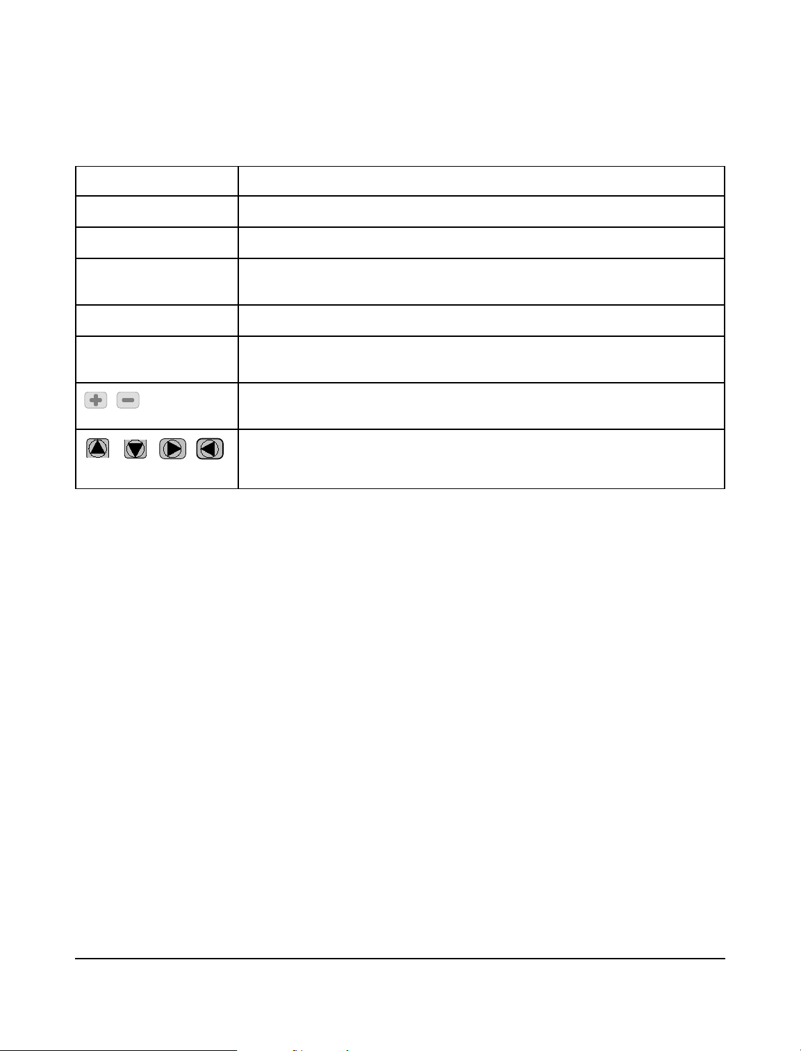
Typographic Conventions Used in this Manual
Style Example Definition
CANCEL
TEST RESULTS Text which appear on the Phase 3 unit display
Add Test
|{}
b+T
, Represents clickable icons which appear on the PC screen when running
, , , ,
>, ?, <, =
Softkeys which appear on the Phase 3 unit display
Text which appears on the PC screen when running Phase3pc software, or
text which describes the action of an icon located on the PC screen.
Represents an actual key on a computer keyboard.
Represents the simultaneous pressing of the specified key combination on a
computer keyboard.
Phase3pc software
Represent special function keys located on the front panel of the Phase 3 unit.
Refer to section 4.1.1 for a detailed explanation of how these keys are used.
Definitions # Page xiv

Phase 3 OPERATING MANUAL
1 SPECIFICATIONS
1.1 Tests Performed
• Defibrillator Energy
• Defibrillator Charge Time
• Defibrillator Cardioversion
• Automated External Defibrillator (AED) Performance
• ECG Monitor Performance
• Pacer Pulse Characteristics
• Pacer Noise Immunity
• Pacer Sensitivity
• Pacer Refractory Periods
1.2 Performance Specifications
1.2.1 Energy Measurement, General
• Load resistance: 50 ohms ±1%, non-inductive
• Signal sampling interval: 11.4 microseconds
• Measurement time window: 58.368 milliseconds
• ECG amplitude at defib pads: 1 mV QRS
• WAVEFORM (oscilloscope) Output
High Range: 1000:1 amplitude attenuation
Low Range: 200:1 amplitude attenuation
• Waveform Playback: Captured discharge can be viewed via
ECG outputs and paddles, with 200:1
time base expansion
Specifications/Chapter 1 # Page 1

Phase 3 OPERATING MANUAL
1.2.2 Defibrillator High Range Energy Test
• Energy Measurement:
Range: 0.0 to 600.0 Joules
Accuracy: ±1% ±2 LSD
• Voltage Measurement:
Range: 0 to 5000 Volts
Accuracy: ±1% ±2 LSD
• Current Measurement:
Range: 0.0 to 100.0 Amps
Accuracy: ±1% ±2 LSD
• Pulse Width Measurement:
Range: 0.10 to 58.36 milliseconds
Accuracy: ±1% ±2 LSD
• Trigger Level: 80 Volts
• Playback Amplitude: 1 millivolt per 1000 volts on Lead II;
• Test Pulse: 126 Joules ±10%
1 millivolt per 2000 volts at defib pads
1.2.3 Defibrillator Low Range Energy Test
• Energy Measurement:
Range: 0.0 to 50.0 Joules
Accuracy: ±1% ±2 LSD
• Voltage Measurement:
Range: 0 to 1000 Volts
Accuracy: ±1% ±2 LSD
• Current Measurement:
Range: 0.0 to 20.0 Amps
Accuracy: ±1% ±2 LSD
• Pulse Width Measurement:
Range: 0.10 to 58.36 milliseconds
Accuracy: ±1% ±2 LSD
• Trigger Level: 16 Volts
• Playback Amplitude: 1 millivolt per 200 volts on Lead II;
1 millivolt per 400 volts at defib paddles
• Test Pulse: 46 Joules ±10%
Specifications/Chapter 1 # Page 2

Phase 3 OPERATING MANUAL
1.2.4 Defibrillator Charge Time Test
• Energy, Voltage, Current and Pulse Width specifications per 1.2.1.
• Charge Time Measurement:
Range: 0.0 to 99.9 seconds
Accuracy: ±1 LSD
1.2.5 Defibrillator Cardioversion Test
• Energy, Voltage, Current and Pulse Width specifications per 1.2.1, 1.2.2.
• Sync Delay Measurement:
Range: -200 to +800 milliseconds
Accuracy: ±1 LSD
• Delay Target: +20 to +65 msec window when enabled
• Sync Point: Selectable, peak of ECG Q or R wave
1.2.6 AED Performance Test
• Energy specifications per 1.2.1.
• Test Method: Verification of AED shock advisory
report for specified ECG arrhythmia
1.2.7 Pacemaker Pulse Test
• Pulse Amplitude Measurement:
Range: 4 to 250 milliamps, all loads
Accuracy: ±1% ±1 LSD
• Pulse Rate Measurement:
Range: 20 to 220 pulses per minute (PPM)
Accuracy: ±1% ±1 LSD
• Pulse Width Measurement:
Range: 0.5 to 58.36 milliseconds
Accuracy: ±1% ±2 LSD
• Test Load Range: 50 to 1600 ohms, in 50 ohm steps
• WAVEFORM output: 50 milliamps per volt, all loads
• Measurement Methods: Average, leading edge, trailing edge, peak
• Test Pulse: 125 mA ±10%
Specifications/Chapter 1 # Page 3

Phase 3 OPERATING MANUAL
1.2.8 Pacemaker Noise Immunity Test
• Test Waveform: 50Hz or 60Hz sine wave
• Noise Amplitude Range: 0.00 to 6.00 millivolts peak-to-peak
• Noise Amplitude Precision: 0.023 millivolts
1.2.9 Pacemaker Sensitivity Test
• Test Waveform: Square (SQRP), Triangle (TRIP) or
• Waveform Width: 10, 25, 40, 100, or 200 milliseconds
• Amplitude Range: 0.00 to 3.00 millivolts peak
1.2.10 Pacemaker Refractory Period Test
• Paced Refractory Period (PRP):
Range: 50 to 750 milliseconds
Accuracy: ±1 LSD
• Sensed Refractory Period (SRP):
Range: 50 to 750 milliseconds
Accuracy: ±1 LSD
Haversine (SSQP) pulse
Specifications/Chapter 1 # Page 4

Phase 3 OPERATING MANUAL
1.3 ECG Simulator
1.3.1 Performance Test Waveforms
• DC Pulse, 4 seconds
• Square Wave, 2 Hz
• Triangle Wave, 2 Hz
• Sine Wave @ 0.1, 0.5, 10, 20, 40, 50, 60, 70, or 100 Hz
1.3.2 Normal Sinus Rhythm
• 30, 60, 90, 120, 150, 180, 240 or 300 BPM
1.3.3 Cardioversion, Shock Advisory and AED Test Waveforms
• Atrial Fibrillation, Coarse (AFIB1)
• Atrial Fibrillation, Fine AFIB2)
• Asystole (ASYS1) (random, low-frequency baseline fluctuation)
• Asystole - Flat (ASYS2) (flat line/zero volts)
• Supraventricular Tachycardia (SVTACH)
• Ventricular Tachycardia at 140 BPM (VTACH1)
• Ventricular Tachycardia at 160 BPM (VTACH2)
• Ventricular Tachycardia at 190 BPM (VTACH3)
• Torsades de Pointes at 200 BPM (PVTACH)
• Coarse Ventricular Fibrillation (VFIB1)
• Fine Ventricular Fibrillation (VFIB2)
1.3.4 Arrhythmia Simulations
• Second Degree A-V Block
• Premature Atrial Contraction (PAC)
• Right Bundle Branch Block (RBBB)
• Premature Ventricular Contraction (PVC)
• R-on-T PVC
• Multifocal PVC
• Run of 5 PVC
• Bigeminy
• Trigeminy
1.3.5 Pacemaker Test Waveforms
• SQRP (square) Pacer Trigger, width = 10, 25, 40, 100 or 200 msec
• TRIP (triangle) Pacer Trigger, width = 10, 25, 40, 100 or 200 msec
• SSQP (haversine) Pacer Trigger, width = 10, 25, 40, 100 or 200 msec
Specifications/Chapter 1 # Page 5

Phase 3 OPERATING MANUAL
1.3.6 Performance Specifications
• Output Level: Selectable, 1 millivolt, 2 millivolt or 0.5 millivolt into ECG Lead II
• Impedance: 500 ohms
• Accuracy:
Rate: ±0.2%
Amplitude: ±2%
1.4 Non-Volatile Memory
1.4.1 Memory Type
• EEPROM
1.4.2 Data Capacity
• 80 Test Records
• 10 Defibrillator Waveform Records
• 32 Automated Test Sequences
1.4.3 Test Record Content
• Device ID (equipment control number)
• Time/date of test
• Test type (manual or AutoSequence test)
• Device type (standard defibrillator, or AED)
• Up to 10 defibrillator energy tests (or 32 AED energy tests)
• 1 defibrillator charge time test
• Up to 4 defibrillator cardioversion tests
• Up to 12 ECG performance tests
• Up to 10 pacer pulse tests
• 1 pacer noise immunity test
• Up to 2 pacer sensitivity tests
• Up to 2 pacer refractory period tests
1.4.4 Waveform Record Content
• Device ID (equipment control number)
• Time/date of test
• Energy, voltage, current, and pulse width of captured discharge
• Discharge waveform data
Specifications/Chapter 1 # Page 6

Phase 3 OPERATING MANUAL
1.5 Interface
1.5.1 User Interface
• LCD (5.2" x 1.5"; 40 characters x 8 lines text; 240 x 64 pixel graphics)
• 4 front panel soft-keys + 4 navigation keys
• Audio beeper
• LCD contrast adjustment (side panel)
1.5.2 Defibrillator Input
• Molex 42820-3212
1.5.3 Pacemaker Input
• 2 x safety-style banana jack (red (+)/black (-))
1.5.4 ECG Simulator Outputs
• 10 x safety-style banana jack (RA; RL; LA; LL; V1-V6)
1.5.5 Defibrillator/Pacer Waveform Output
• 1/8" monaural phono jack with signal on tip, sleeve ground
1.5.6 High-Level ECG Output
• 1/8" monaural phono jack with signal on tip, sleeve ground
1.5.7 USB Port
• Connector: Type "B"
• Protocol: USB 1.1 or USB 2.0 compatible
• Data Transfer Rate: 64 bytes per millisecond
1.5.8 Serial (RS-232) Port
• Connector: DB9 Male
• Protocol: RS-232C; bidirectional; CTS handshaking;
9600 baud; 8 data bits; no parity bit;
1 stop bit
1.5.9 Keyboard Port
• Connector: PS/2 (6-pin miniDIN female)
• Protocol: Per PS/2 standard
Specifications/Chapter 1 # Page 7

Phase 3 OPERATING MANUAL
1.5.10 Power Supply
• Battery: Internal 12.5V/1.4A-h NiCad, P/N 3310-007
• Battery Life: 24 hours of use between charges
• Battery Charger: See AC adapter, section 1.8.1
• DC Voltage Input: 18VDC, 0.8A max
1.6 Environment
• 15EC to 40EC
• 15% to 90% RH
• Altitude: 2000m max.
• Indoor Use Only
• Category II
• Pollution Degree 2
1.7 Dimensions
• 9.5" (24cm) W x 8" (20cm) H x 5.5" (14cm) D
• Weight 3 lbs. (1.4 kg)
1.8 Accessories
1.8.1 Standard Accessories
• Adult Paddle Adapter (P/N 7400-442)
• Adult Paddle Adapter Cable (P/N 7200-444)
• USB Cable (A-B Male) (P/N 3140-440)
• Phase3pc Software on CDROM (P/N 6950-004)
• Operator's Manual on CDROM (P/N 6950-004)
• AC Adapter , one of:
- North America:
- UK:
- Europe:
- Australia/China:
*
Note: The mains power supply voltage fluctuation is not to exceed +/- 10% of
*
the specified nominal supply voltage or the specified input voltage range,
whichever is applicable.
120VAC/60Hz to 15VDC/1A (P/N 3000-500)
240VAC/50Hz to 15VDC/0.8A (P/N 3000-501)
100-264VAC 50/60Hz to 18VDC/0.8A (3000-440 + 3000-442)
100-264VAC 50/60Hz to 18VDC/0.8A (3000-440 + 3000-441)
Specifications/Chapter 1 # Page 8

Phase 3 OPERATING MANUAL
1.8.2 Optional Accessories
• ECG-to-Banana Adapter Set (P/N 7500-425 - Set of 10)
• Internal Paddle Adapter Set (P/N 7400-443)
• Variable Load Module (P/N 7900-460)
• Variable Load Module Software on CDROM (P/N 6950-004)
• Unterminated Defibrillator Adapter Cable (P/N 7200-445)
• Unterminated Pacemaker Adapter Cable (P/N 7200-446)
• Terminated Defibrillator Adapter Cable - Banana Jacks (P/N 7200-448)
• Computer Interface Cable (RS-232), DB9F - DB9F (P/N 3140-400)
• Computer Interface Adapter (RS-232), DB9M - DB25F (P/N 3140-401)
• Printer Interface Adapter, DB9M - DB25M (P/N 3140-402)
• Citizen iDP-3110 Serial Printer (P/N 7050-055)
• Barcode Pen Reader, RS-232 (P/N 7050-050)
• Barcode CCD Scanner, RS-232 (P/N 7600-051)
• Barcode CCD Scanner, PS/2 (P/N 7600-052)
Compliance With Standards
Phase 3 has been certified to meet the following safety standards:
CAN/CSA-C22.2 No. 61010-1-(2 Edition) - Safety Requirements for Electrical Equipment for
Measurement, Control, and Laboratory Use, Part 1: General Requirements
UL Std. No. 61010-1 (2 Edition) - Safety Requirements for Electrical Equipment for
nd
Measurement, Control, and Laboratory Use - Part 1: General Requirements
IEC/EN 61010-1 (Ed.2.0) - Safety requirements for electrical equipment for measurement, control,
and laboratory use - Part 1: General requirement
Following manufacture, all units are subjected to, and have passed the requirements of the ‘Routine
Tests’ defined in Annex F of the above Standard(s).
nd
Specifications/Chapter 1 # Page 9

Phase 3 OPERATING MANUAL
Specifications/Chapter 1 # Page 10

Phase 3 OPERATING MANUAL
2 OVERVIEW
2.1 General Description
2.1.1 Test Capabilities
Phase 3 is a portable, automated system for verifying performance of defibrillators and
transcutaneous pacemakers of all types, including defibrillators which produce monophasic,
biphasic, and Multipulse Biowave discharges. Phase 3 provides menu-driven procedures which
allow you to test:
®
Delivered Energ y Measure the output energy of a defibrillator when it is discharged
into Phase 3. Along with energy in joules, also measures peak
voltage, current and duration of the discharge pulse.
Charg e Tim e Measure the time required for a defibrillator to charge up to its
maximum energy setting. After charging, measures the energy
delivered when the defibrillator is discharged into Phase 3.
Cardioversion Verify the ability of a defibrillator to correctly synchronize its
discharge to the QRS complex of the electrocardiogram.
Monitor Perfo rm ance Check the ECG monitor and chart recorder of a defibrillator with
performance waves, normal sinus rhythms, and a wide variety of
arrhythmias provided by the full-featured ECG simulator of
Phase 3.
AED Perform anc e Verify the ability of an Automated External Defibrillator (AED) to
correctly recognize life-threatening arrhythmias and advise delivery
of a shock at the appropriate energy.
Pulse Charac te ristic s Measure amplitude, rate and width of pulses generated by the
transcutaneous pacemaker of a defibrillator.
Overview/Chapter 2 # Page 11

Phase 3 OPERATING MANUAL
Noise Immunity Verify the ability of a transcutaneous pacemaker to reject line
frequency interference in the electrocardiogram.
Sensitivity Determine the smallest QRS complex that a transcutaneous
pacemaker will recognize as valid.
Re frac to ry Period Determine the paced refractory period (PRP) and sensed refractory
period (SRP) of a transcutaneous pacemaker.
Phase 3 incorporates one fixed 50 ohm load for defibrillator testing, and a variable load for pacer
testing that may be set from 50 to 1600 ohms in 50 ohm steps. To accommodate requirements of
the IEC60601-2-4 standard for defibrillators, the Variable Load Mo d u le (VLM) may be added to
Phase 3 as an optional accessory, allowing the user to perform energy tests with an alternative
defibrillator load ranging from 25 to 175 ohms in 25 ohm steps.
Phase 3 may be powered from its internal NiCad battery or from AC power using the accessory
adapter provided with the unit. The rechargeable battery can provide up to 24 hours of continuous
operation.
Phase 3 is small and light-weight, allowing you to easily carry the analyzer to institutional areas
where defibrillators are located. As you perform each test, results can be saved to the non-volatile
Data Log of Phase 3, for later review on the LCD, output to an attached printer, or download to a
personal computer.
2.1.2 Data Log
Phase 3 incorporates a non-volatile memory or "data log" which is used to save test results or Test
Re cords. For each defibrillator tested, Phase 3 can create a Test Record containing energy, charge
time and cardioversion test results, which may be combined with results from ECG and
transcutaneous pacemaker tests. The non-volatile memory of Phase 3 provides storage for up to 80
such Test Records, each Record being identified by the control number of the defibrillator tested.
The non-volatile memory can also be used to store up to 10 defibrillator discharge waveforms as
Wave Records. Test Records and Wave Records can be downloaded to a personal computer by
means of Phase3pc software, included on CDROM with the analyzer.
Overview/Chapter 2 # Page 12
 Loading...