

DATREND Systems Oxitest Plus 7 Operating Manual

Oxitest
Plus7
Pulse Oximeter Tester
Operating Manual


Oxitest Plus7
Pulse Oximeter Tester
Operating Manual
© 2003-2014 Datrend Systems Inc.
Unit 130 - 4020 Viking Way
Richmond, BC • CANADA • V6V 2L4
Tel: 800.667.6557 (North America Only) or
604.291.7747 • Fax 604.294.2355
e-mail customerservice@datrend.com


To order this manual, use Part Number 6100-105
Revision
E New Corporate Address 2014-Dec-09
Revision History
Description Date
Copyright
Datrend Systems Inc. (“DSI”) agrees to a limited copyright release that allows you to reproduce manuals
and other printed materials for use in service training programs and other technical publications. If you
would like other reproductions or distributions, submit a written request to Datrend Systems Inc.
Unpacking and Inspection
Follow standard receiving practices upon receipt of the instrument. Check the shipping carton for
damage. If damage is found, stop unpacking the instrument. Notify the freight carrier and ask for an
agent to be present while the instrument is unpacked. There are no special unpacking instructions, but
be careful not to damage the instrument when unpacking it. Inspect the instrument for physical damage
such as bent or broken parts, dents, or scratches.
Claims
Our routine method of shipment is via common carrier. Upon delivery, if physical damage is found,
retain all packing materials in their original condition and contact the carrier immediately to file a claim.
If the instrument is delivered in good physical condition but does not operate within specifications, or if
there are any other problems not caused by shipping damage, please contact your local sales
representative or DSI immediately.
Standard Terms and Conditions
Refunds & Credits
Please note only serialized products (products labeled with a distinct serial number) and accessories are
eligible for partial refund and/or credit. Non-serialized parts and accessory items (cables, carrying cases,
auxiliary modules, etc.) are not eligible for return or refund. In order to receive a partial refund/credit, the
product must not have been damaged, and must be returned complete (meaning all manuals, cables,
accessories, etc.) within 90 days of original purchase and in “as new” and resalable condition. The
Return Procedure must be followed.
Return Procedure
Every product returned for refund/credit must be accompanied by a Return Material Authorization (RMA)
number, obtained from Datrend Customer Service. All items being returned must be sent prepaid
(freight, duty, brokerage, and taxes ) to our factory location.
Restocking Charges
Products returned within 30 days of original purchase are subject to a minimum restocking fee of 15%.
Products returned in excess of 30 days after purchase, but prior to 90 days, are subject to a minimum
restocking fee of 20%. Additional charges for damage and/or missing parts and accessories will be
applied to all returns. Products which are not in “as new” and resalable condition, are not eligible for
credit return and will be returned to the customer at their expense.
Certification
This instrument was thoroughly tested and inspected and found to meet DSI's manufacturing
specifications when it was shipped from the factory. Calibration measurements are traceable to the
National Research Council of Canada (NRC) and/or the National Institute of Standards and Technology
(NIST). Devices for which there are no NRC/NIST calibration standards are measured against in-house
performance standards using accepted test procedures.

Warranty
Warranty and Product Support
Datrend Systems Inc. ("DSI") warrants this instrument to be free from defects in materials and
workmanship under normal use and service for one (1) year from the date of original purchase. This
warranty will be automatically extended to a maximum of five (5) years from the date of original
purchase provided that calibration is performed on an annual basis by a Datrend Authorized Service
Center (refer to Section 6.2 of this manual).
This warranty is subject to the following limitations:
! Oxitest Battery Pack: 90 day limited warranty
! Standard Accessories: 90 day limited warranty
! Re-calibration of the instrument, which has a recommended annual calibration frequency, is not
covered under the warranty.
During the warranty period DSI will, at our option, either repair or replace a product that proves to be
defective at no charge; provided you return the product (shipping, duty, brokerage and taxes prepaid) to
DSI. Any and all transportation charges incurred are the responsibility of the purchaser and are not
included within this warranty. This warranty extends only to the original purchaser and does not cover
damage from abuse, neglect, accident or misuse or as the result of service or modification by other than
DSI. IN NO EVENT SHALL DATREND SYSTEMS INC. BE LIABLE FOR CONSEQUENTIAL
DAMAGES.
No warranty shall apply when damage is caused by any of the following:
! Power failure, surges, or spikes,
! Damage in transit or when moving the instrument,
! Improper power supply such as low voltage, incorrect voltage, defective wiring or inadequate fuses,
! Accident, alteration, abuse or misuse of the instrument,
! Fire, water damage, theft, war, riot, hostility, acts of God, such as hurricanes, floods, etc.
Only serialized products (those items bearing a distinct serial number tag) and their standard accessory
items are covered under this warranty. PHYSICAL DAMAGE CAUSED BY MISUSE OR PHYSICAL
ABUSE IS NOT COVERED UNDER THE WARRANTY. Items such as cables and non-serialized
modules are not covered under this warranty.
This warranty gives you specific legal rights and you may have other rights, which vary from province to
province, state to state, or country to country. This warranty is limited to repairing the instrument to
DSI's specifications.
When you return a DSI instrument for service, repair or calibration, we recommend shipment using the
original shipping foam and container. If the original packing materials are not available, we recommend
the following guide for repackaging:
! Use a double-walled carton of sufficient strength for the weight being shipped.
! Use heavy paper or cardboard to protect all instrument surfaces. Use non-abrasive material around
all projecting parts.
! Use at least four inches of tightly packed, industrial-approved, shock-absorbent material all around
the instrument.
DSI will not be responsible for lost shipments or instruments received in damaged condition due to
improper packaging or handling. All warranty claim shipments must be made on a prepaid basis
(freight, duty, brokerage, and taxes). No returns will be accepted without a Return Materials
Authorization ("RMA) number. Please contact Datrend at 1-800-667-6557 to obtain an RMA number
and receive help with shipping/customs documentation.

Warranty Disclaimer
Should you elect to have your instrument serviced and/or calibrated by someone other than Datrend
Systems, please be advised that the original warranty covering your product becomes void when the
tamper-resistant Quality Seal is removed or broken without proper factory authorization. We strongly
recommend, therefore, that you send your instrument to Datrend Systems for service and calibration,
especially during the original warranty period.
In all cases, breaking the tamper-resistant Quality Seal should be avoided at all cost, as this seal is the
key to your original instrument warranty. In the event that the seal must be broken to gain internal
access to the instrument (e.g., in the case of a customer-installed firmware upgrade), you must first
contact Datrend Systems at 1-800-667-6557. You will be required to provide us with the serial number
for your instrument as well as a valid reason for breaking the Quality Seal. You should break this seal
only after you have received factory authorization. Do not break the Quality Seal before you have
contacted us! Following these steps will help ensure that you will retain the original warranty on your
instrument without interruption.
WARNING
Unauthorized user modifications or application beyond the published specifications may result in
electrical shock hazards or improper operation. Datrend Systems will not be responsible for any injuries
sustained due to unauthorized equipment modifications.
DSI DISCLAIMS ALL OTHER WARRANTIES, EXPRESSED OR IMPLIED, INCLUDING ANY
WARRANTY OF MERCHANTABILITY OR FITNESS FOR A PARTICULAR PURPOSE OR
APPLICATION.
THIS PRODUCT CONTAINS NO USERSERVICEABLE COMPONENTS. UNAUTHORIZED
REMOVAL OF THE INSTRUMENT COVER SHALL
VOID THIS AND ALL OTHER EXPRESSED OR
IMPLIED WARRANTIES.

Nellcor® is a registered trademark of Tyco Healthcare
QBasic™ and Visual Basic™ are trademarks of Microsoft Corp.
MS-DOS® is a registered trademark of Microsoft Corp.

OXITEST PLUS 7 OPERATING MANUAL
Table of Contents
1. Specifications . . . . . . . . . . . . . . . . . . . . . . . . . . . . . . . . . . . . . . . . . . . . . . . . . . . . . . . . . . . . . . . . . . . . 1
2. Overview . . . . . . . . . . . . . . . . . . . . . . . . . . . . . . . . . . . . . . . . . . . . . . . . . . . . . . . . . . . . . . . . . . . . . . . . 5
2.1 General Description . . . . . . . . . . . . . . . . . . . . . . . . . . . . . . . . . . . . . . . . . . . . . . . . . . . . . . . . . . 5
2.2 Detailed Description . . . . . . . . . . . . . . . . . . . . . . . . . . . . . . . . . . . . . . . . . . . . . . . . . . . . . . . . . . 6
3. Operation . . . . . . . . . . . . . . . . . . . . . . . . . . . . . . . . . . . . . . . . . . . . . . . . . . . . . . . . . . . . . . . . . . . . . . . 9
3.1 General Description . . . . . . . . . . . . . . . . . . . . . . . . . . . . . . . . . . . . . . . . . . . . . . . . . . . . . . . . . . 9
3.2 Powering Up, and Modifying the Oxitest Plus 7 Menu . . . . . . . . . . . . . . . . . . . . . . . . . . . . . . . 11
3.3 Setting Display Contrast . . . . . . . . . . . . . . . . . . . . . . . . . . . . . . . . . . . . . . . . . . . . . . . . . . . . . . 12
3.4 Choosing an Oximeter . . . . . . . . . . . . . . . . . . . . . . . . . . . . . . . . . . . . . . . . . . . . . . . . . . . . . . . 13
3.5 Selecting an SpO2 level . . . . . . . . . . . . . . . . . . . . . . . . . . . . . . . . . . . . . . . . . . . . . . . . . . . . . . 14
3.6 Selecting a Heart Rate . . . . . . . . . . . . . . . . . . . . . . . . . . . . . . . . . . . . . . . . . . . . . . . . . . . . . . . 15
3.7 Selecting a Pulse Amplitude . . . . . . . . . . . . . . . . . . . . . . . . . . . . . . . . . . . . . . . . . . . . . . . . . . 15
3.8 Status Indicator . . . . . . . . . . . . . . . . . . . . . . . . . . . . . . . . . . . . . . . . . . . . . . . . . . . . . . . . . . . . 16
3.9 Selecting Motion Artifact Simulation . . . . . . . . . . . . . . . . . . . . . . . . . . . . . . . . . . . . . . . . . . . . . 17
3.10 Selecting Auto Presets . . . . . . . . . . . . . . . . . . . . . . . . . . . . . . . . . . . . . . . . . . . . . . . . . . . . . . . 18
3.11 Selecting Alarm Tests . . . . . . . . . . . . . . . . . . . . . . . . . . . . . . . . . . . . . . . . . . . . . . . . . . . . . . . 18
3.12 Saving and Printing Test Results . . . . . . . . . . . . . . . . . . . . . . . . . . . . . . . . . . . . . . . . . . . . . . . 22
3.13 Using the Nellcor Sensor Port . . . . . . . . . . . . . . . . . . . . . . . . . . . . . . . . . . . . . . . . . . . . . . . . . 24
3.14 ECG Trigger Output . . . . . . . . . . . . . . . . . . . . . . . . . . . . . . . . . . . . . . . . . . . . . . . . . . . . . . . . . 26
3.15 Recharging the Battery . . . . . . . . . . . . . . . . . . . . . . . . . . . . . . . . . . . . . . . . . . . . . . . . . . . . . . 27
4. Computer Control and RS-232 . . . . . . . . . . . . . . . . . . . . . . . . . . . . . . . . . . . . . . . . . . . . . . . . . . . . . . 29
4.1 Electrical Interface . . . . . . . . . . . . . . . . . . . . . . . . . . . . . . . . . . . . . . . . . . . . . . . . . . . . . . . . . . 29
4.2 Mechanical Interface . . . . . . . . . . . . . . . . . . . . . . . . . . . . . . . . . . . . . . . . . . . . . . . . . . . . . . . . 30
4.3 Functional Description . . . . . . . . . . . . . . . . . . . . . . . . . . . . . . . . . . . . . . . . . . . . . . . . . . . . . . . 30
4.4 Command Definitions . . . . . . . . . . . . . . . . . . . . . . . . . . . . . . . . . . . . . . . . . . . . . . . . . . . . . . . . 31
4.4.1 Select Oximeter and Initialize Simulation . . . . . . . . . . . . . . . . . . . . . . . . . . . . . . . . . . 31
4.4.2 Set SpO2 Command . . . . . . . . . . . . . . . . . . . . . . . . . . . . . . . . . . . . . . . . . . . . . . . . . . 32
4.4.3 Set Heart Rate Command . . . . . . . . . . . . . . . . . . . . . . . . . . . . . . . . . . . . . . . . . . . . . . 32
4.4.4 Set Pulse Amplitude Command . . . . . . . . . . . . . . . . . . . . . . . . . . . . . . . . . . . . . . . . . 32
4.4.5 Activate Artifact Simulation . . . . . . . . . . . . . . . . . . . . . . . . . . . . . . . . . . . . . . . . . . . . . 33
4.4.6 Activate Auto Preset Protocol . . . . . . . . . . . . . . . . . . . . . . . . . . . . . . . . . . . . . . . . . . . 33
4.4.7 Download Test Report . . . . . . . . . . . . . . . . . . . . . . . . . . . . . . . . . . . . . . . . . . . . . . . . 33
4.4.8 Download Manual Record . . . . . . . . . . . . . . . . . . . . . . . . . . . . . . . . . . . . . . . . . . . . . . 34
4.4.9 Download Auto Preset Test Record . . . . . . . . . . . . . . . . . . . . . . . . . . . . . . . . . . . . . . 34
4.4.10 Download Alarm Test Record . . . . . . . . . . . . . . . . . . . . . . . . . . . . . . . . . . . . . . . . . . . 34
4.4.11 Erase All Test Records . . . . . . . . . . . . . . . . . . . . . . . . . . . . . . . . . . . . . . . . . . . . . . . . 34
4.4.12 Command Summary . . . . . . . . . . . . . . . . . . . . . . . . . . . . . . . . . . . . . . . . . . . . . . . . . . 35
4.5 Programming Example . . . . . . . . . . . . . . . . . . . . . . . . . . . . . . . . . . . . . . . . . . . . . . . . . . . . . . 36
5. Test Usage Guidelines . . . . . . . . . . . . . . . . . . . . . . . . . . . . . . . . . . . . . . . . . . . . . . . . . . . . . . . . . . . . 39
5.1 General Rules . . . . . . . . . . . . . . . . . . . . . . . . . . . . . . . . . . . . . . . . . . . . . . . . . . . . . . . . . . . . . 39
5.1.1 Interpretation of Results . . . . . . . . . . . . . . . . . . . . . . . . . . . . . . . . . . . . . . . . . . . . . . . 39
5.1.2 Probe/Sensor Interface . . . . . . . . . . . . . . . . . . . . . . . . . . . . . . . . . . . . . . . . . . . . . . . . 40
5.2 Diagnosing Sensor Faults . . . . . . . . . . . . . . . . . . . . . . . . . . . . . . . . . . . . . . . . . . . . . . . . . . . . 48
5.3 Cross-Manufacturer Compatibility . . . . . . . . . . . . . . . . . . . . . . . . . . . . . . . . . . . . . . . . . . . . . . 49
Table of Contents # Page i

OXITEST PLUS 7 OPERATING MANUAL
6. Routine Maintenance . . . . . . . . . . . . . . . . . . . . . . . . . . . . . . . . . . . . . . . . . . . . . . . . . . . . . . . . . . . . . 51
6.1 Probe Cleaning . . . . . . . . . . . . . . . . . . . . . . . . . . . . . . . . . . . . . . . . . . . . . . . . . . . . . . . . . . . . 51
6.2 Calibration . . . . . . . . . . . . . . . . . . . . . . . . . . . . . . . . . . . . . . . . . . . . . . . . . . . . . . . . . . . . . . . . 52
Table of Contents # Page ii

OXITEST PLUS 7 OPERATING MANUAL
1. Specifications
1.1 Saturation (SpO2)
Range of adjustment is according to pulse oximeter manufacturer and/or model.
Masimo, Mindray, Nellcor, and Nellcor OEM's (e.g., Critikon; Protocol; Philips; etc.):
Variable from 35% to 100% in steps of 1%
SpO2 presets at 35, 70, 80, 90, 93, and 97%
Selected EnviteC, Hewlett-Packard, Nihon Kohden, and Philips models:
Variable from 55% to 100% in steps of 1%
SpO2 presets at 55, 70, 80, 90, 93, and 97%
All other manufacturers and models:
Variable from 70% to 100% in steps of 1%
SpO2 presets at 70, 80, 90, 93, and 97%
1.2 SpO2 Accuracy
All supported oximeters except Datex and Invivo oximeters:
55 to 100% SpO2: ±1% at specified SpO2 presets
35% SpO2: ±2%
Nellcor accuracy specified with either DS100A sensor, or with SpO2 calibration
selected via Nellcor Port.
Specifications/Chapter 1 # Page 1

OXITEST PLUS 7 OPERATING MANUAL
Datex and Invivo oximeters:
±1% at 97, 93% SpO
±2% at 90, 80, 70% SpO
2
2
1.3 Heart Rate
Variable from 20 to 250 beats per minute (BPM) in 1 BPM steps
Presets: 30, 60, 90, 120, 180, 240 BPM
Accuracy: ± 1 BPM
1.4 Pulse Amplitude
Variable from zero (no blood flow) to 100% (normal adult pulse) in 1% steps.
Presets: 100%, 30%, 10%, and 5%
Accuracy: ± 1%
1.5 Signal Artifact
Four preset simulations:
Movement
Tapping (Spike artifact)
Shivering (Tremor artifact)
Shake Table (2.5Hz Sinewave)
1.6 Auto Presets
Nine preset patient simulations. Factory default Auto Presets are:
Normal Adult Hypoxia
Tachycardia Bradycardia
Low Perfusion No Perfusion
Movement Artifact Neonate
Tremor (Shivering Artifact)
Auto Preset parameters may be user-programmed via the RS-232 port.
Specifications/Chapter 1 # Page 2

OXITEST PLUS 7 OPERATING MANUAL
1.7 Alarm Tests
Five automated test sequences for determining oximeter alarm response time to Low SpO2;
Low Heart Rate; High Heart Rate; Low Perfusion; and Motion Artifact conditions. Also
determines time required for oximeter alarm to self-clear after test conditions are returned to
normal.
Alarm Test parameters may be user-programmed via the RS-232 port.
1.8 Memory
Auto Preset and Alarm Test results saved in battery-backed, non-volatile Memory, along
with up to 20 PASS/FAIL records from manually-conducted tests. Test results in Memory
may be printed as a Test Report via optional external Printer, or may be downloaded via RS232 port to personal computer or automated tester.
1.9 Pulse Oximeter Make / Model
Major makes and models supported. Refer to the
Oxitest Plus 7
product CD, or
www.datrend.com, for a detailed listing.
1.10 User Interface
Display:
LCD - 20 character x 2 line
Keypad - 15 keys:
PULSE OX, SPO2 (%), HEART RATE (preset), HR•, HR–, PULSE AMP (preset),
PUL• , PUL–, PASS, FAIL, AUTO (preset), ALARM TEST, START/STOP (alarm
test), ERASE (memory), PRINT
1.11 Nellcor Port
Allows temporary connection of Nellcor pulse oximeter sensors for selection of sensorspecific SpO2 calibration curve. Intended for high-accuracy testing of all Nellcor disposable
and re-usable sensors.
Specifications/Chapter 1 # Page 3

OXITEST PLUS 7 OPERATING MANUAL
1.12 Serial / Printer Interface
Mechanical: 5 Pin Mini-DIN
Electrical: Bi-directional RS-232. 9600 baud, 8 bits, no parity, 1 stop.
1.13 Power Supply
Battery: 7.2V rechargeable.
Capacity: 1.4 Ah
Battery life: 40 hours continuous
1.14 Environment
15OC to 40OC, 10% to 90% RH
Indoor Use Only
Category II
Pollution Degree 2
Altitude 2000m (max)
Note: Mains supply voltage fluctuations not to exceed +/- 10% of the nominal supply
voltage.
1.15 Standard Accessories
AC Adapter (all models): 100-240 VAC 50/60 Hz to 12 VDC adaptor; P/N: 3000-025
And one of the Blade Sets for P/N 3000-025:
North America: P/N: 3000-401
Europe: P/N: 3000-402
United Kingdom: P/N: 3000-403
Australia: P/N: 3000-404
1.16 Optional Accessories
For a complete list of available accessories, visit www.datrend.com or contact Datrend
Customer Service (see section 6.2 for contact details)
Specifications/Chapter 1 # Page 4

OXITEST PLUS 7 OPERATING MANUAL
2. Overview
2.1 General Description
The
Oxitest Plus 7
the operation of pulse oximeters and their optical sensors. In use, a pulse oximeter sensor is placed
on the
Oxitest Plus 7
sensor which simulates a predetermined oxygen saturation (SpO2) level, at a given heart rate and
signal strength (pulse amplitude). Proper operation of the pulse oximeter is confirmed if the
parameters measured by the oximeter match those generated by
Pulse Oximeter Tester is a portable, battery operated device designed to test
probe.
Oxitest Plus 7
transmits an optical signal to the pulse oximeter
Oxitest Plus 7
.
Oxitest Plus 7
tapping the oximeter sensor, shivering or trembling, and shake table laboratory test.
provides four simulations of patient motion artifacts: gross body movement,
Oxitest Plus 7
also provides 9 preset simulations to test oximeters under realistic clinical conditions, and five
automated oximeter alarm tests. High accuracy testing of Nellcor sensors is available through the
use of Nellcor’s sensor specific calibration curves. Auto Preset, Alarm and manual test results may
be output to a printer, or downloaded to a PC or automated tester for easy documentation.
Most problems with pulse oximeters can be traced to complete or partial failure of the oximeter
sensor (the photo sensor, one of the two light transmitting elements [LEDs], the cable, or the
connector).
Oxitest Plus 7
will assist in diagnosing sensor failures by providing an indication of
the status of the oximeter’s LEDs.
For comprehensive testing of sensors when no pulse oximeter is available, Datrend provides a
companion test instrument: Sensitest.
Overview/Chapter 2 # Page 5

OXITEST PLUS 7 OPERATING MANUAL
2.2 Detailed Description
Pulse oximeters commonly utilized in hospitals are based on the principle of the absorption of light
by blood, at two separate wavelengths, 660 nm and 940 nm. Specifically, the relationship between
the absorption of light for Oxygenated Haemoglobin (HbO2) and reduced Haemoglobin (Hb)
allows the calculation of HbO2, and subsequently oxygen saturation.
A typical pulse oximeter probe incorporates one 660 nm light emitting diode (LED) and one 940
nm LED on the transmitting side of the sensor, and one broad spectrum photosensitive element on
the receiving side of the sensor. The pulse oximeter activates the LEDs in a particular sequence
which allows the received signals to be correctly interpreted. The light passes through a portion of
the body of the patient, commonly the finger, ear, toe, scalp, etc., and falls on the photosensitive
element, which translates the attenuated light signals into electrical signals.
Using various means, the pulse oximeters interpret the
ratio
of the attenuated signals at the two
wavelengths as a percentage of oxygen saturation. A more detailed description of the process, and
the scientific principles of pulse oximetry can be found in the article “Knowing Your Pulse
Oximetry Monitors”, S. Ackerman and P. Weith, Medical Electronics, February, 1995, pp 82-86.
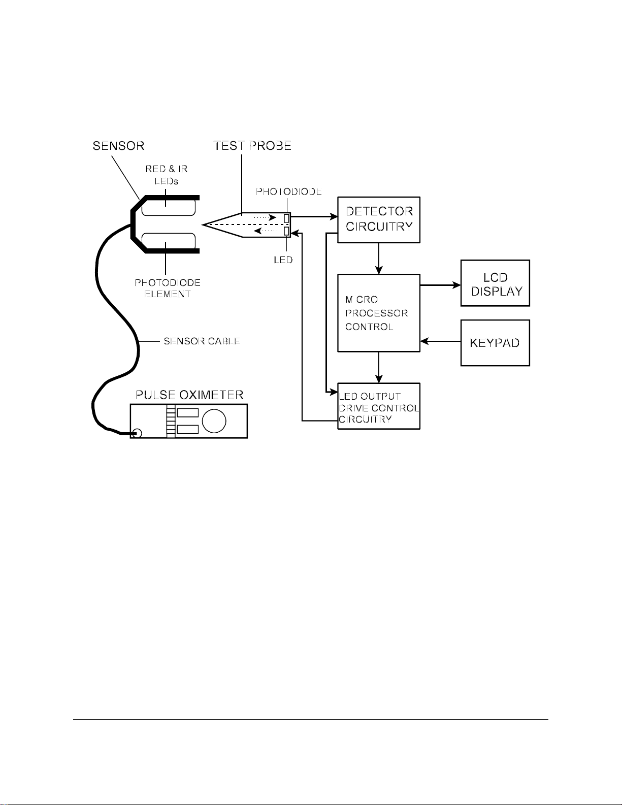
A block diagram of the
Oxitest Plus 7
is provided in Figure 1. The
Oxitest Plus 7
incorporates a
probe, resembling a finger, which is placed between the transmitting and receiving elements of the
oximeter. The
Oxitest Plus 7
probe intercepts the light signals produced by the pulse oximeter
and generates pulses of light that are controlled in level, and which simulate the light levels which
would normally be received by the pulse oximeter’s photosensitive element, at predetermined
oxygen saturation levels.
Overview/Chapter 2 # Page 6
OXITEST PLUS 7 OPERATING MANUAL
Figure 1 - Block Diagram
A photodiode in the
and generates an electrical signal which is analysed by the
microprocessor, in turn, produces control signals to drive an LED in the
Oxitest Plus 7
probe intercepts the oximeter's red and infrared light signals,
Oxitest Plus 7
microprocessor. The
Oxitest Plus 7
probe,
with the correct timing and amplitude appropriate to the oximeter under test. Light from the
Oxitest Plus 7
LED is detected by the photodiode in the oximeter sensor, causing the oximeter to
display simulated SpO2 and heart rate indications.
Overview/Chapter 2 # Page 7

OXITEST PLUS 7 OPERATING MANUAL
Overview/Chapter 2 # Page 8

OXITEST PLUS 7 OPERATING MANUAL
3. Operation
3.1 General Description
The
Oxitest Plus 7
oximeter, its cable and sensor. A test is performed by applying the oximeter sensor to the
Plus 7
Plus 7
probe, after first setting up the test parameters on
are depicted in Figure 2 and Figure 3, and are referred to throughout the rest of section 3.
The following procedure should be followed for correct operation:
provides a quick and efficient method of testing the overall operation of a pulse
Oxitest Plus 7
. The features of
Oxitest
Oxitest
1. Turn the
Oxitest Plus 7
ON by rotating the test probe 90 degrees from its protective
storage compartment.
2. Following power-up, select an oximeter make (Pulse Ox) from the menu. Set the SpO2,
Heart Rate and Pulse Amp to the desired settings using the appropriately labelled push
button keys on the front panel. See sections 3.2 through 3.7 for further details. Default
values for SpO2, Heart Rate and Pulse Amp on selection of a new oximeter are 97%, 60
BPM and 100% respectively.
3. Turn on the oximeter and examine the sensor to determine which side has the LEDs (this
side will radiate red light). Apply the sensor to the test probe, orienting the sensor
with the
LEDs on the underside of the probe.
4. Wait for the
5. Change
oximeter alarms when SpO2 and/or heart rate exceed corresponding alarm thresholds.
Optionally, decrease the Pulse Amp and note how the oximeter's SpO2 and heart rate may
be affected by low tissue perfusion.
6. Remove the oximeter sensor from the test probe.
Oxitest Plus 7
Oxitest Plus 7
to display "RED+IR OK!" on its LCD.
SpO2 and Heart Rate and note the oximeter's response. Verify the
7. Select a new oximeter (if required) and go back to step (3), or turn
rotating the test probe back into the storage compartment.
Operation/Chapter 3 # Page 9
Oxitest Plus 7
OFF by
 Loading...