


DATOptic RM12-S6.TB User Manual

6Gb/s SATA RAID TB
T12-S6.TB - Desktop
RM12-S6.TB - Rackmount
User Manual
Version: 1.0
Issue Date: October, 2013

ARCHTTP PROXY SERVER INSTALLATION
5.5 For Mac OS 10.X
The ArcHttp proxy server is provided on the software CD delivered
with 6Gb/s SATA RAID controller or download from the www.areca.
com.tw. The rmware embedded McRAID storage manager can
congure and monitor the 6Gb/s SATA RAID controller via ArcHttp
proxy server. The Archttp proxy server for Mac pro, please refer to
Chapter 4.6 "Driver Installation" for Mac 10.X.
5.6 ArcHttp Conguration
The ArcHttp proxy server will automatically assign one additional
port for setup its conguration. If you want to change the "archttpsrv.conf" setting up of ArcHttp proxy server conguration, for
example: General Conguration, Mail Conguration, and SNMP
Conguration, please start Web Browser http:\\localhost: Cfg Assistant. Such as http:\\localhost: 81. The port number for rst controller McRAID storage manager is ArcHttp proxy server congura-
tion port number plus 1.
• General Conguration:
Binding IP: Restrict ArcHttp proxy server to bind only single
interface (If more than one physical network in the server).
HTTP Port#: Value 1~65535.
Display HTTP Connection Information To Console: Select “Yes" to
show Http send bytes and receive bytes information in the console.
Scanning PCI Device: Select “Yes” for ARC-1XXX series controller.
Scanning RS-232 Device: No.
Scanning Inband Device: No.
111
ARCHTTP PROXY SERVER INSTALLATION
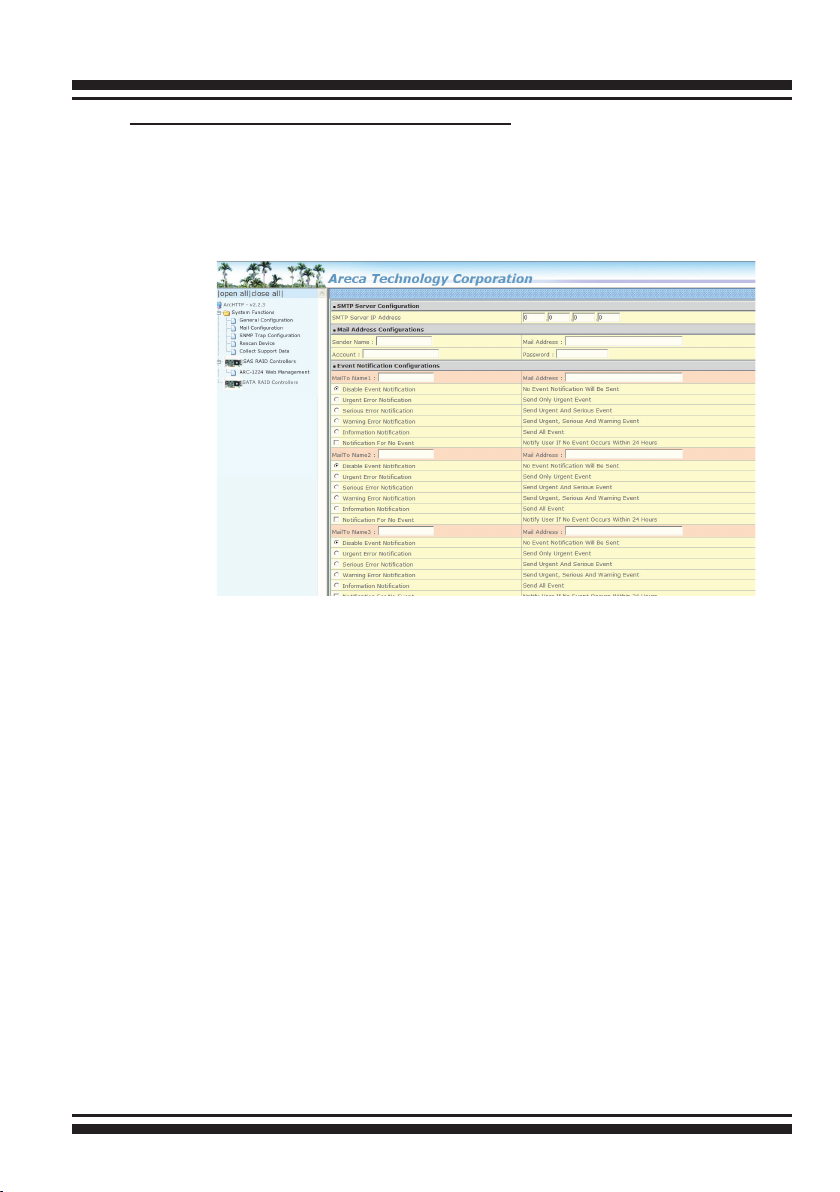
• Mail (alert by Mail) Conguration:
To enable the controller to send the email function, you need to
congure the SMTP function on the ArcHttp software. To enable
the RAID controller email sending function, click on the “Mail Conguration” link. The "SMTP Server Congurations" menu will show
as following:
When you open the mail conguration page, you will see the
following settings:
(1). SMTP Server Conguration:
SMTP Server IP Address: Enter the SMTP server IP address which is
not McRAID storage manager IP.
Ex: 192.168.0.2.
(2). Mail Address Congurations:
Sender Name: Enter the sender name that will be shown on the
outgoing mail.
Ex: RaidController_1.
Mail address: Enter the sender email that will be shown on the
outgoing mail, but don’t type IP to replace domain name.
Ex: RaidController_1@areca.com.tw.
Account: Enter the valid account if your SMTP mail server requires
authentication.
Password: Enter the valid password if your SMTP mail server
requires authentication.
112

ARCHTTP PROXY SERVER INSTALLATION
(3). Event Notication Congurations:
MailTo Name: Enter the alert receiver name that will be shown on
the outgoing mail.
Mail Address: Enter the alert receiver mail address.
Ex: admin@areca.com.tw.
According to your requirement, set the corresponding event level :
Disable Event Notication: No event notication will be sent.
Urgent Error Notication: Send only urgent events.
Serious Error Notication: Send urgent and serious events.
Warning Error Notication: Send urgent, serious and warning
events.
Information Notication: Send all events.
Notication For No Event: Notify user if no event occurs within 24
hours.
• SNMP Traps Conguration:
To enable the RAID controller to send the SNMP traps to client
SNMP manager using the IP address assigned to the operating
system, such as Net-SNMP manager, you can simply use the SNMP
function on the ArcHttp proxy server software. To enable the
RAID controller SNMP traps sending function, click on the “SNMP
Conguration” link. The Archttp proxy only provide one direction
to send the trap to the SNMP manager without needing to install
the SNMP extension agent on the host. If SNMP manager requests
to query the SNMP information from RAID controller, please refer
the Appendix C "SNMP Operation & Installation". The “SNMP traps
Conguration” menu will be shown as following:
113

ARCHTTP PROXY SERVER INSTALLATION
When you open the SNMP traps conguration page, you will see the
following settings:
(1). SNMP Trap Congurations
Enter the SNMP trap IP address.
(2). SNMP System Congurations
Community name acts as a password to screen accesses to the
SNMP agent of a particular network device. Type the community
names of the SNMP agent in this eld. Before access is granted to
a request station, this station must incorporate a valid community
name into its request; otherwise, the SNMP agent will deny access
to the system. Most network devices use “public” as default of their
community names. This value is case-sensitive.
(3). SNMP Trap Notication Congurations
Before the client side SNMP manager application accepts the 6Gb/
s SATA RAID controller traps, it is necessary to integrate the MIB
into the management application’s database of events and status
indicator codes. This process is known as compiling the MIB into
the application. This process is highly vendor-specic and should be
well-covered in the User’s Guide of your SNMP application. Ensure
the compilation process successfully integrates the contents of the
areca_SATA.mib le into the traps database. Please refer to Appen-
dix C of “SNMP Operation & Installation”. The MIBs le resides at:
<CD-ROM>\packages\SNMP_MIBs on the software CD.
Note:
Event Notication Table refer to Appendix D.
After you conrm and submit congurations, you can use
"Generate Test Event" feature to make sure these settings are
correct.
• Rescan Device Conguration:
Let's assume you've put all Areca RAID adapters to a system.
The Archttp scans the RAID adapters on the system and create
an individual adapter icon located on left column of the Archttp
Congurations screen. This adapter icon is for user to launch web
browser RAID manager. If there is any RAID adapter missed on the
system start-up, you can use the "Rescan Device" function. The
114
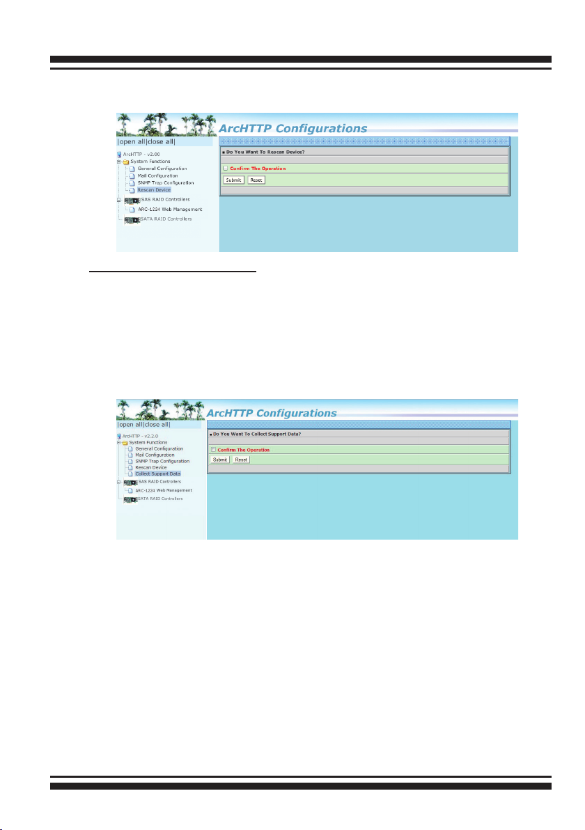
ARCHTTP PROXY SERVER INSTALLATION
"Rescan Device" function is a procedure which forces the archttp to
rescan the targets to allow a missed RAID adapter to be added.
• Collect Support Data:
Areca has added the “Collect Support Data” option on the Archttp
proxy server utility to download a support le (le name:ctlrxxxxxxx.log) with all necessary information (system information,
conguration, disk information, eventlog). The “Collect Support
Data” function will be automatically started when ERROR or
SERIOUS event has occurred.
115

WEB BROWSER-BASED CONFIGURATION
6. Web Browser-based Conguration
Before using the rmware-based browser McRAID storage manager, do
the initial setup and installation of this product. If you need to boot up
the operating system from a RAID volume set, you must rst create a
RAID volume by using McBIOS RAID manager. Please refer to section
3.3 “Using Quick Volume /Raid Setup” conguration for information on
creating this initial volume set.
The McRAID storage manager is rmware-based utility, which is accessible via the web browser installed on your operating system. The web
browser-based McRAID storage manager is a HTML-based application,
which utilizes the browser (IE, Safari, Netscape and Mozilla etc) installed on your monitor station.
It can be accessed through the in-band PCIe 2.0 bus or out-of-band
LAN port. The in-band method can launch the web browser-based
McRAID storage manager via archttp proxy server. The rmware-
embedded web browser-based McRAID storage manager allows local
or remote to access it from any standard internet browser via a LAN
or WAN with no software or patches required. The rmware contains
SMTP manager monitors all system events and user can select either
single or multiple user notications to be sent via LAN with “Plain English” e-mails. The rmware-embedded SNMP agent allows remote to
monitor events via LAN with no SNMP agent required.
• Create RAID set
• Expand RAID set
• Dene volume set
• Add physical drive
• Modify volume set
• Modify RAID level/stripe size
• Dene pass-through disk drives
• Modify system function
• Update rmware
• Designate drives as hot spares
6.1 Start-up McRAID Storage Manager
With the McRAID storage manager, you can locally manage a system containing a 6Gb/s SATA RAID controller that has Windows,
116

WEB BROWSER-BASED CONFIGURATION
Linux or more and a supported browser. A locally managed system requires all of the following components:
• A supported web browser, which should already be installed on
the system.
• Install ArcHttp proxy server on the SATA RAID system. (Refer to
Chapter 5, Archttp Proxy Server Installation)
• Remote and managed systems must have a TCP/IP connection.
• Start-up McRAID Storage Manager from Windows
Local Administration
Screen captures in this section are taken from a Windows XP
installation. If you are running another version of Windows, your
screens may look different, but the ArcHttp proxy server installation is essentially the same.
There “Areca RAID Controller” icon bar window start appearing
in the taskbar, double-click to launch the ArcHTTP Conguration
screen. Or click on the “Start” button in the Windows task bar and
then click “Program”, select the “McRAID” and run “ Archttp proxy
server”. The “ArcHTTP Congurations” dialog box appears.
When you click the archttp proxy server utility, it shows all RAID
adapters available on the system and create an individual adapter
icon located on left column of the “Archttp Congurations” screen.
This adapter icon is for user to launch the selected RAID adapter
web browser RAID manager.
The “Enter Network Password” dialog screen appears, type the
117

WEB BROWSER-BASED CONFIGURATION
User Name and Password. The RAID controller default User Name
is “admin” and the Password is “0000”. After entering the user
name and password, press Enter key to access the McRAID storage manager.
• Start-up McRAID Storage Manager from Linux/
FreeBSD/Solaris/Mac Local Administration
To congure the internal 6Gb/s SATA RAID controller. You need
to know its IP address. You can nd the IP address assigned by
the Archttp proxy server installation:Binding IP:[X.X.X.X] and
controller listen port.
(1). You can click the individual adapter icon located on left
column of the “Archttp Congurations” screen or Launch your
McRAID storage manager by entering http://[Computer IP
Address]:[Port Number] in the web browser.
(2). When connection is established, the "System Login" screen
appears. The 6Gb/s SATA RAID controller default User Name is
“admin” and the Password is “0000”.
• Start-up McRAID Storage Manager Through Ethernet Port (Out-of-Band)
Areca now offers an alternative means of communication for the
PCIe RAID controller – web browser-based McRAID storage man-
ager program. User can access the built-in conguration without
needing system starting up running the ArcHttp proxy sever.
The web browser-based McRAID storage manager program is an
HTML-based application, which utilizes the browser installed on
your remote system.
To ensure proper communications between the PCIe RAID controller and web browser-based McRAID storage manager, Please
connect the RAID controller LAN port to any LAN switch port. The
controller has embedded the TCP/IP & Web Browser-based RAID
manager in the rmware. User can remote manage the RAID
controller without adding any user specic software (platform
independent) via standard web browsers directly connected to the
10/100Mbit RJ45 LAN port.
118
WEB BROWSER-BASED CONFIGURATION
To congure RAID controller on a remote machine, you need to
know its IP address. The IP address will default show in McBIOS
RAID manager of “Ethernet Conguration” or “System Information” option. Launch your rmware-embedded TCP/IP & web
browser-based McRAID storage manager by entering http://[IP
Address] in the web browser.
Note:
You can nd controller Ethernet port IP address in McBIOS
RAID manager “System Information” option.
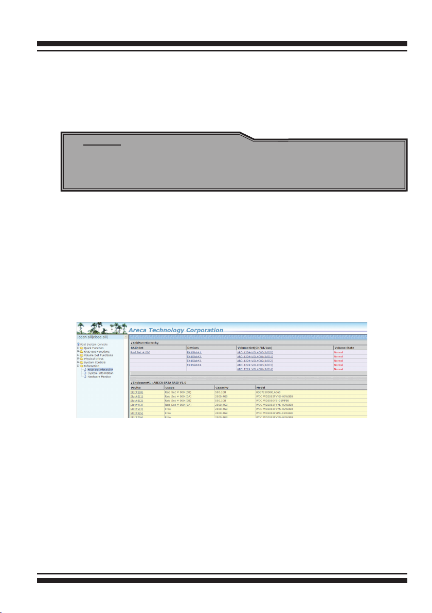
6.2 McRAID Storage Manager
The McRAID storage manager initial start-up screen displays the
current conguration of your 6Gb/s SATA RAID controller. It displays the “Raid Set List”, “Volume Set List”, and “Physical Disk List”.
The RAID set information, volume set information, and drive infor-
mation can also be viewed by clicking on the “RAID Set Hierarchy”
screen. The current conguration can also be viewed by clicking on
“RAID Set Hierarchy” in the main menu.
To display RAID set information, move the mouse cursor to the desired RAID set number, then click it. The RAID set information will
be displayed. To display volume set information, move the mouse
cursor to the desired volume set number, then click it. The volume set information will be displayed. To display drive information,
move the mouse cursor to the desired physical drive number, then
click it. The drive information will be displayed.
119
WEB BROWSER-BASED CONFIGURATION
6.3 Main Menu
The main menu shows all available functions, accessible by clicking
on the appropriate link.
Individual Category Description
Quick Function Create a default conguration, which is based
Raid Set Functions Create a customized RAID set.
Volume Set Functions Create customized volume sets and modify the
Physical Drives Create pass through disks and modify the existing
System Controls Setting the RAID system conguration.
Information Viewing the controller information. The Raid Set
on the number of physical disks installed; it can
modify the volume set Capacity, Raid Level, and
Stripe Size.
existed volume sets parameter.
pass through drives parameters. Also provides
the function to identify disk drives (blinking fault
LED).
Hierarchy can be viewed through the “Raid Set
Hierarchy” item.
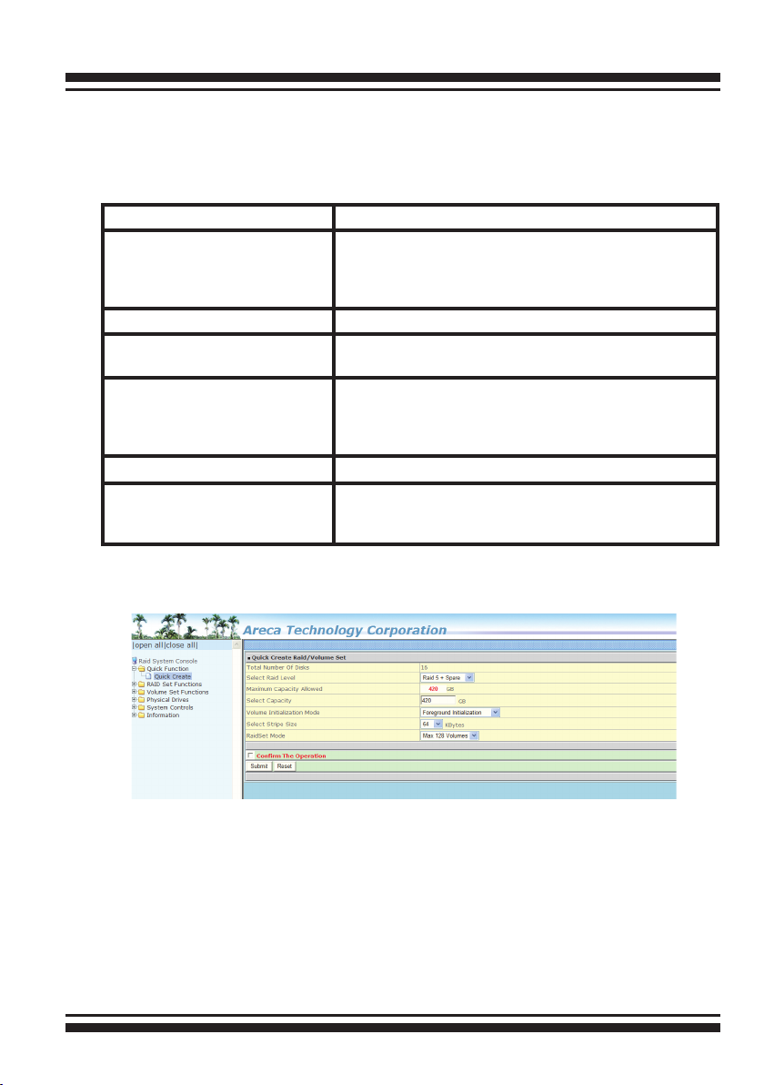
6.4 Quick Function
The number of physical drives in the 6Gb/s SATA RAID controller
determines the Raid Levels that can be implemented with the RAID
set. You can create a RAID set associated with exactly one volume
set. The user can change the Raid Level, Capacity, Initialization
Mode and Stripe Size. A hot spare option is also created, depending
on the exist conguration. Click the “Conrm The Operation” check
box and click on the “Submit” button in the “Quick Create” screen,
the RAID set and volume set will start to initialize.
120
WEB BROWSER-BASED CONFIGURATION
Note:
In “Quick Create”, your volume set is automatically congured
based on the number of disks in your system. Use the “Raid
Set Functions” and “Volume Set Functions” if you prefer to
customize your volume set, or RAID 30/50/60 volume set.
6.5 Raid Set Functions
Use the “Raid Set Function” and “Volume Set Function” if you prefer to customize your volume set. Manual conguration can provide
full control of the RAID set settings, but it will take longer to com-
plete than the “Quick Volume/Raid Setup” conguration. Select the
“Raid Set Function” to manually congure the RAID set for the rst
time or delete and recongure existing RAID sets. (A RAID set is a
group of disks containing one or more volume sets.)
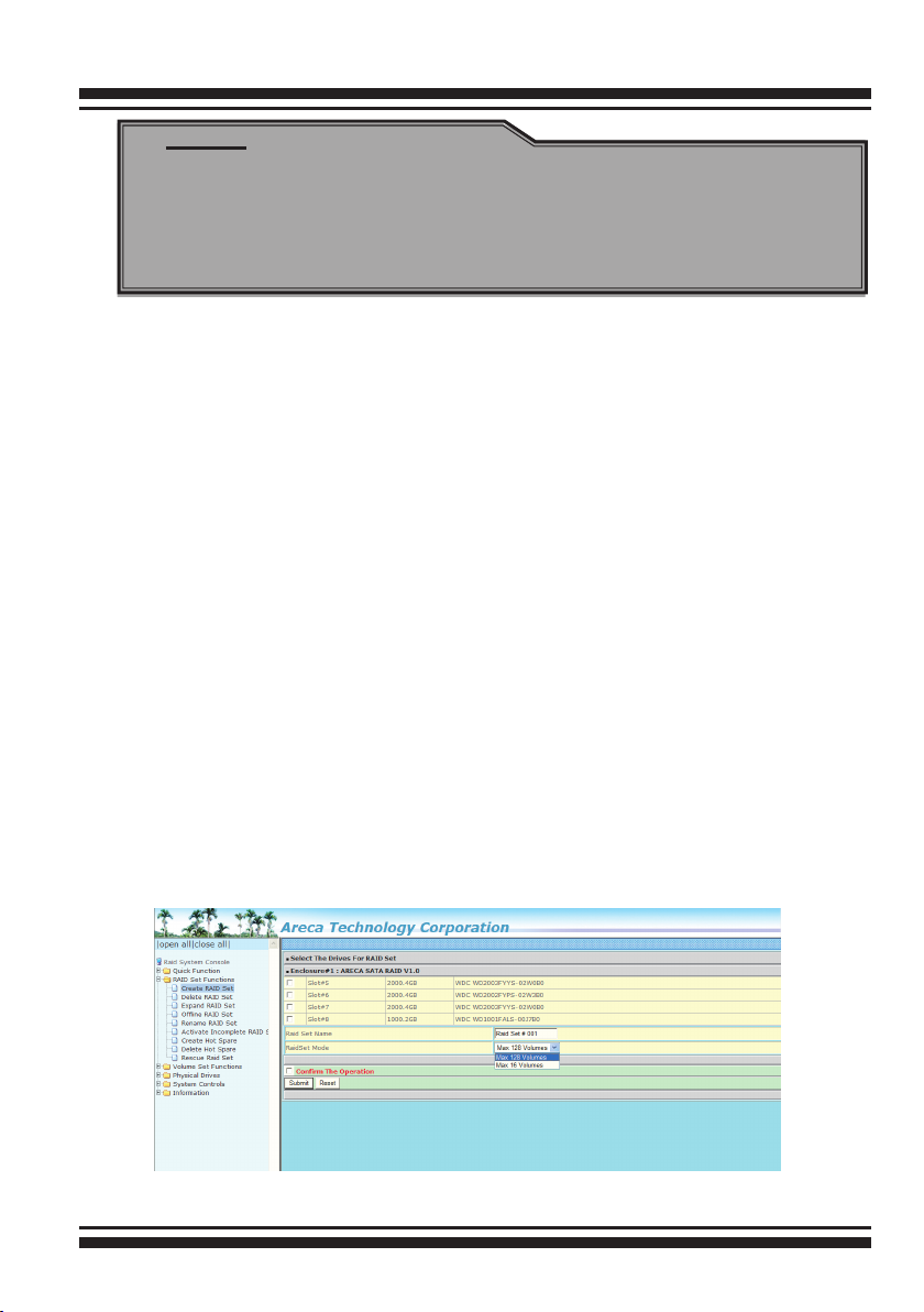
6.5.1 Create Raid Set
To create a RAID set, click on the “Create Raid Set” link. A “Select
The Drive For RAID Set” screen is displayed showing the drive(s)
connected to the current controller and enclosures. Click on the
selected physical drives within the current RAID set. Enter 1 to 15
alphanumeric characters to dene a unique identier for a RAID
set. The default RAID set name will always appear as “Raid Set
#”. Click the “Conrm The Operation” check box and click on the
“Submit” button on the screen; the RAID set will start to initialize.
If you have available disk member, you can repeat above proce-
dures to dene another RAID sets.
121

WEB BROWSER-BASED CONFIGURATION
128 volumes is the default mode for SAS RAID controller, the 16
volumes mode is used for support roaming this raidset to 3Gb/s
SATA RAID controllers. The 3Gb/s SATA RAID controller is de-
signed to support up to 16 volumes only. You have to use “Max
16 volumes” on the raidset mode if you plan to roam this raidset
between 6Gb/s SATA RAID controller and 3Gb/s SATA RAID controller.
Note:
To create RAID 30/50/60 volume, you need create multiple
RAID sets rst (up to 8 RAID sets) with the same disk
numbers on each RAID set. The max no. disk drives per
RAID set: 24 for RAID 0/10(1E)/3/5/6/30/50/60.
6.5.2 Delete Raid Set
To delete a RAID set, click on the “Deleted Raid Set” link. A
“Select The RAID Set To Delete” screen is displayed showing all
exist RAID sets in the current controller. Click the RAID set num-
ber which you want to delete in the select column on the delete
screen. Then, click the “Conrm The Operation” check box and
click on the “Submit” button in the screen to delete it. The volume
sets included in the “Delete RAID Set”. It will be deleted by this
action. But for the Raid 30/50/60, you need to delete the volumes
belonging to those RAID sets.
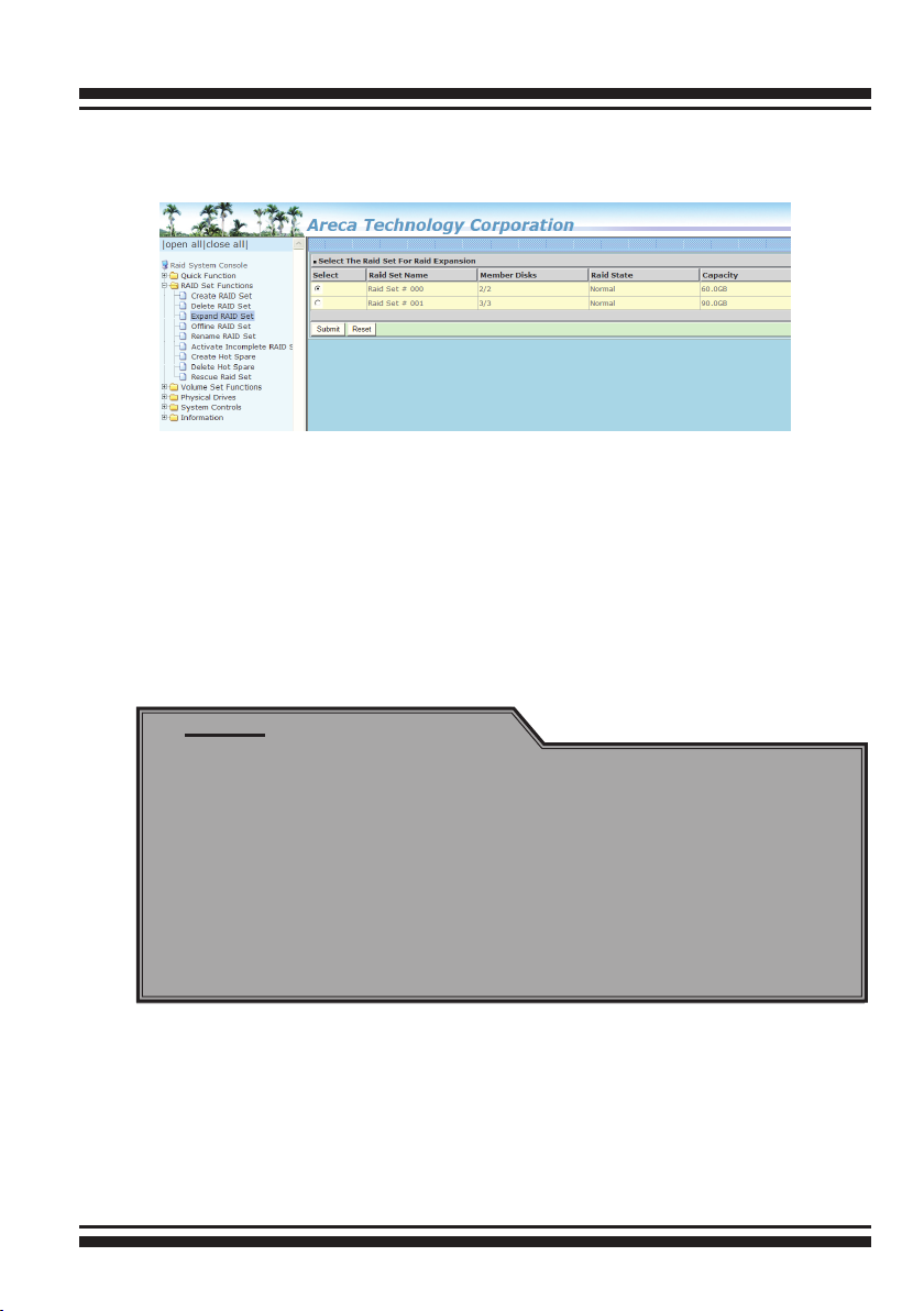
6.5.3 Expand Raid Set
Instead of deleting a RAID set and recreating it with additional
disk drives, the “Expand Raid Set” function allows the users to
add disk drives to the RAID set that have already been created.
To expand a RAID set:
122
WEB BROWSER-BASED CONFIGURATION
Select the “Expand Raid Set” option. If there is an available disk,
then the “Select SATA Drives For Raid Set Expansion” screen
appears.
Select the target RAID set by clicking on the appropriate radio
button. Select the target disk by clicking on the appropriate check
box. Click on the "Submit" button to start the expansion on the
RAID set. The new additional capacity can be utilized by one or
more volume sets. The volume sets associated with this RAID set
appear for you to have chance to modify RAID level or stripe size.
Follow the instruction presented in the “Modify Volume Set ” to
modify the volume sets; operation system specic utilities may be
required to expand operating system partitions.
Note:
1. Once the “Expand Raid Set” process has started, user can
not stop it. The process must be completed.
2. If a disk drive fails during RAID set expansion and a hot
spare is available, an auto rebuild operation will occur after
the RAID set expansion completes.
3. RAID 30/50/60 does not support the "Expand Raid set".
4. RAID set expansion is a quite critical process, we strongly
recommend customer backup data before expand. Unex-
pected accident may cause serious data corruption.
6.5.4 Ofine Raid Set
This function is for customer being able to unmount and remount
a multi-disk volume. All Hdds of the selected RAID set will be put
into ofine state, spun down and fault LED in fast blinking mode.
User can remove those Hdds and insert new Hdds on those empty
slots without needing power down the controller.
123

WEB BROWSER-BASED CONFIGURATION
6.5.5 Rename Raid Set
The default RAID set name will always appear as “Raid Set #”
when it is rst created by the controller. The "Rename Raid Set"
function is for customer to rename the default RAID set name.
To rename a RAID set from a group of RAID sets:
(1). Click on the ”Rename Raid Set" link.
(2). Click the RAID set check box from the list that you wish to
rename. Click the “Submit” button. The following screen appears.
Use this option to rename the RAID set name.
6.5.6 Activate Incomplete Raid Set
If one of the disk drives is removed in power off state, the RAID
set state will change to “Incomplete State”. If the user wants to
continue to operate the controller without power-off the 6Gb/s
SATA RAID controller, the user can use the “Activate Incomplete
Raid Set” option to active the RAID set. After the user completes
this function, the Raid State will change to “Degraded Mode” and
start to work.
To activate the incomplete the RAID set, click on the “Activate
Raid Set” link. A “Select The RAID SET To Activate” screen is
124
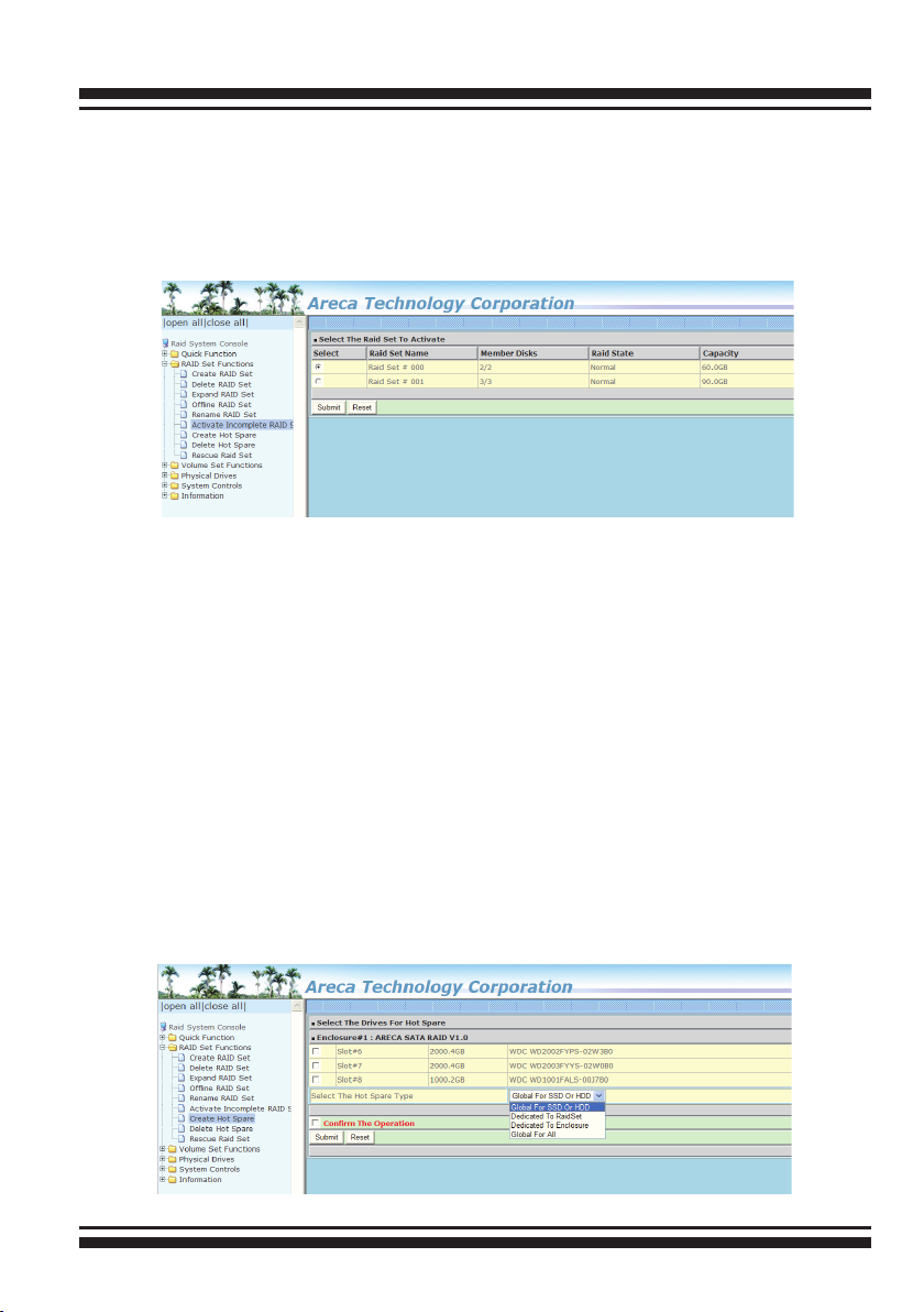
WEB BROWSER-BASED CONFIGURATION
displayed showing all RAID sets existing on the current controller.
Click the RAID set number to activate in the select column.
Click on the “Submit” button on the screen to activate the RAID
set that had a disk removed (or failed) in the power off state.
The 6Gb/s SATA RAID controller will continue to work in degraded
mode.
6.5.7 Create Hot Spare
When you choose the “Create Hot Spare” option in the “Raid Set
Function”, all unused physical devices connected to the current
controller appear. Select the target disk by clicking on the ap-
propriate check box. Click the “Conrm The Operation” check
box and click the “Submit” button in the screen to create the hot
spares. The “Create Hot Spare” gives you the ability to dene a
global or dedicated hot spare. Unlike “Global Hot Spare” which
can be used with any RAID sets, “Dedicated Hot Spare” can only
be used with a specic RAID set or Enclosure. Under “Global For
SSD or HDD” option, SSD hot spare is used to rebuild failed SSD
and HDD hot spare for rebuild failed HDD. When a disk drive fails
in the RAID set or enclosure with a dedicated hot spare is pre-set,
data on the disk drive is rebuild automatically on the dedicated
hot spare disk.
125

WEB BROWSER-BASED CONFIGURATION
6.5.8 Delete Hot Spare
Select the target hot spare disk to delete by clicking on the ap-
propriate check box. Click the “Conrm The Operation” check
box and click the “Submit” button on the screen to delete the hot
spares.
6.5.9 Rescue Raid Set
When the system is powered off in the RAID set update/creation
period, the conguration possibly could disappear due to this abnormal condition. The “RESCUE” function can recover the missing
RAID set information. The RAID controller uses the time as the
RAID set signature. The RAID set may have different time after
the RAID set is recovered. The “SIGANT” function can regenerate
the signature for the RAID set.
Caution:
Please contact us to make sure if you need to use rescue
function. Improperly usage may cause conguration
corruption.
126

WEB BROWSER-BASED CONFIGURATION
6.6 Volume Set Functions
A volume set is seen by the host system as a single logical device.
It is organized in a RAID level with one or more physical disks.
RAID level refers to the level of data performance and protection of
a volume set. A volume set capacity can consume all or a portion
of the disk capacity available in a RAID set. Multiple volume sets
can exist on a group of disks in a RAID set. Additional volume sets
created in a specied RAID set will reside on all the physical disks
in the RAID set. Thus each volume set on the RAID set will have its
data spread evenly across all the disks in the RAID set.
The following summaries are the volume set features for the 6Gb/s
SATA RAID controller.
1. Volume sets of different RAID levels may coexist on the same
RAID set and up to 128 volume sets per controller.
2. Up to 128 volume sets can be created in a RAID set.
3. The maximum addressable size of a single volume set is not limited to 2TB, because the controller is capable of 64-bit LBA mode.
However the operating system itself may not be capable of addressing more than 2TB.
See Areca website ftp://ftp.areca.com.tw/RaidCards/Docu-
ments/Manual_Spec/ Over2TB_050721.ZIP le for details.
6.6.1 Create Volume Set (0/1/10/3/5/6)
To create volume set from RAID set system, move the cursor bar
to the main menu and click on the “Create Volume Set” link. The
“Select The Raid Set To Create On It” screen will show all RAID
set number. Tick on a RAID set number that you want to create
and then click on the “Submit” button.
The new create volume set attribute allows user to select the
Volume Name, RAID Level, Capacity, Greater Two TB Volume
Support, Initialization Mode, Strip Size, Cache Mode, Tagged
Command Queuing, and SCSI Channel/SCSI ID/SCSI Lun.
127

WEB BROWSER-BASED CONFIGURATION
• Volume Name
The default volume name will always appear as “ARC-12x4-VOL”.
You can rename the volume set providing it does not exceed the
15 characters limit.
• Volume Raid Level
Set the Raid Level for the volume set. Highlight the desired
RAID level from the available RAID levels option.
• Capacity
The maximum volume size is the default initial setting. Enter the
appropriate volume size to t your application.
• Greater Two TB Volume Support
If volume capacity will exceed 2TB, controller will show the
"Greater Two TB Volume Support" sub-menu. Greater Two TB
Volume Support option: "No", "64bit LBA" and "4K Block".
- No
It keeps the volume size with max. 2TB limitation.
- 64bit LBA
This option uses 16 bytes CDB instead of 10 bytes. The
maximum volume capacity is up to 512TB.
This option works on different OS which supports 16 bytes CDB.
Such as:
Windows 2003 with SP1 or later
Linux kernel 2.6.x or later
128

WEB BROWSER-BASED CONFIGURATION
- 4K Block
It changes the sector size from default 512 bytes to 4k bytes.
The maximum volume capacity is up to 16TB. This option works
under Windows platform only. And it can not be converted to
“Dynamic Disk”, because 4k sector size is not a standard format.
For more details, please download Over2TB manual from
http://www.areca.com.tw/support/main.htm
• Initialization Mode
This option is used to dene “Background Initialization”, “Foreground Initialization” or “No Init (To Rescue Volume)”. When
“Background Initialization”, the initialization proceeds as a
background task, the volume set is fully accessible for system
reads and writes. The operating system can instantly access to
the newly created arrays without requiring a reboot and waiting
the initialization complete. When “Foreground Initialization”, the
initialization proceeds must be completed before the volume set
ready for system accesses. There is no initialization happened
when you select “No Init” option. “No Init“ is for customer to
rescue volume without losing data in the disk.
• Stripe Size
This parameter sets the size of the stripe written to each disk
in a RAID 0, 1, 10, 5, 6, 50 or 60 logical drive. You can set the
stripe size to 4 KB, 8 KB, 16 KB, 32 KB, 64 KB, 128 KB, 256KB,
512KB, or 1024KB. A larger stripe size produces better read
performance, especially if your computer does mostly sequential
reads. However, if you are sure that your computer does random reads more often, select a smaller stripe size.
Note:
RAID level 3 and 30 can’t modify the cache strip size.
• Cache Mode
The 6Gb/s SATA RAID controller supports “Write Through” and
“Write Back” cache.
129

WEB BROWSER-BASED CONFIGURATION
•Volume Write Protection
When "Volume Write Protection" is enabled on the "Modify
Volume Set", host commands fail if they are issued to a volume
in that RAID controller and attempt to modify a volume's data
or attributes. Volume Write Protection is used primarily for
customer-initiated disaster recovery testing.
• Volume IO Mode:
The Cache IO and Direct IO cache policies apply to read on a
specic virtual disk. The volume IO mode options are as follows:
- Cache Io
Species that all reads are buffered in the controller cache
memory.
- Direct Io
Species that reads are not buffered in cache memory. When
using direct IO mode, data is transferred to the controller cache
memory and the host system simultaneously during a read
request.
If a subsequent read request requires data from the same data
block, it can be read directly from the controller cache memory.
• Tagged Command Queuing
The “Enabled” option is useful for enhancing overall system
performance under multi-tasking operating systems. The
Command Tag (Drive Channel) function controls the SATA
command tag queuing support for each drive channel. This
function should normally remain “Enabled”. “Disabled” this
function only when using SATA drives that do not support
command tag queuing.
• SCSI Channel/SCSI ID/SCSI Lun
SCSI Channel: The 6Gb/s SATA RAID controller function is simulated as an external SCSI RAID controller. The host bus is represented as a SCSI channel. Choose the SCSI Channel.
SCSI ID: Each SCSI device attached to the SCSI card, as well
as the card itself, must be assigned an unique SCSI ID number.
A SCSI channel can connect up to 15 devices. The 6Gb/s SATA
RAID controller is a large SCSI device. Assign an ID from a list
of SCSI IDs.
130

WEB BROWSER-BASED CONFIGURATION
SCSI LUN: Each SCSI ID can support up to 8 LUNs. Most 6Gb/s
SATA controllers treat each LUN like a SATA disk.
6.6.2 Create Raid30/50/60 (Volume Set
30/50/60)
To create 30/50/60 volume set from RAID set group, move
the cursor bar to the main menu and click on the “Create
Raid30/50/60” link. The “Select The Raid Set To Create Volume
On It” screen will show all RAID set number. Tick on the RAID set
numbers (same disk No per RAID set) that you want to create
and then click on the “Submit” button.
The new create volume set attribute allows user to select the Volume Name, Raid Level, Capacity, Greater Two TB Volume Support,
Initialization Mode, Strip Size, Cache Mode, Tagged Command
Queuing, and SCSI Channel/SCSI ID/SCSI Lun. Please refer to
above section for details description of each item.
Note:
RAID level 30 50 and 60 can support up to eight RAID set
(four pairs), but it can not support expansion and migration.
6.6.3 Delete Volume Set
To delete a volume from RAID set, move the cursor bar to the
main menu and click on the “Delete Volume Set” link. The “Select
The Raid Set To Delete” screen will show all RAID set numbers.
Click a RAID set number and the “Conrm The Operation” check
box and then click the “Submit” button to show all volume set
131

WEB BROWSER-BASED CONFIGURATION
items in the selected RAID set. Click a volume set number and
the “Conrm The Operation” check box and then click the “Submit” button to delete the volume set.
6.6.4 Modify Volume Set
To modify a volume set from a RAID set:
(1). Click on the “Modify Volume Set” link.
(2). Click the volume set check box from the list that you wish to
modify. Click the “Submit” button. The following screen appears.
Use this option to modify the volume set conguration. To modify
volume set attributes, move the cursor bar to the volume set at-
tribute menu and click it. The “Enter The Volume Attribute” screen
appears. Move the cursor to an attribute item and then click the
attribute to modify the value. After you complete the modication,
click the “Conrm The Operation” check box and click the “Submit” button to complete the action. The user can only modify the
last volume set capacity.
6.6.4.1 Volume Growth
Use “Expand RAID Set" function to add disk to a RAID set. The
additional capacity can be used to enlarge the last volume set
size or to create another volume set. The “Modify Volume Set”
132

WEB BROWSER-BASED CONFIGURATION
function can support the “Volume Modication” function. To
expand the last volume set capacity, move the cursor bar to
the “Capacity” item and entry the capacity size. When nished
the above action, click on the "Sumbit" button to complete the
action. The last volume set starts to expand its capacity.
To expand an existing volume noticed:
• Only the last volume can expand capacity.
• When expand volume capacity, you can’t modify stripe size or
modify RAID level simultaneously.
• You can expand volume capacity, but can’t reduce volume
capacity size.
• After volume expansion, the volume capacity can't be
decreased.
For greater 2TB expansion:
• If your system installed in the volume, don't expand the
volume capacity greater 2TB; except your OS and RAID
controller can support boot up from a greater 2TB capacity
device.
• Expand over 2TB used LBA64 mode. Please make sure your
OS supports LBA64 before expand it.
6.6.4.2 Volume Set Migration
Migrating occurs when a volume set is migrating from one RAID
level to another, when a volume set strip size changes, or when
a disk is added to a RAID set. Migration state is displayed in the
volume state area of the “Volume Set Information” screen.
133

WEB BROWSER-BASED CONFIGURATION
Note:
1. If the volume is RAID level 30, 50, or 60, you can not
change the volume to another RAID level. If the volume
is RAID level 0, 1, 10(1E), 3, 5, or 6, you can not change
the volume to RAID level 30, 50, or 60.
2.Power failure may damage the migration data. Please
backup the RAID data before you start the migration
function.
6.6.5 Check Volume Set
To check a volume set from a RAID set:
(1). Click on the “Check Volume Set” link.
(2). Click on the volume set from the list that you wish to check.
Click on “Conrm The Operation” and click on the “Submit” button. Use this option to verify the correctness of the redundant
data in a volume set. For example, in a system with dedicated
parity, volume set check means computing the parity of the data
disk drives and comparing the results to the contents of the
dedicated parity disk drive. The checking percentage can also be
viewed by clicking on “RAID Set Hierarchy” in the main menu.
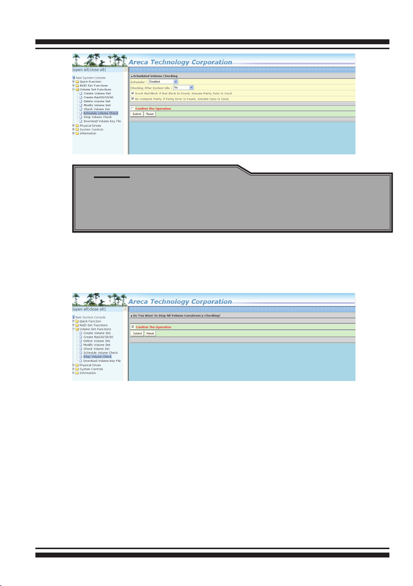
6.6.6 Schedule Volume Check
A volume check is a process that veries the integrity of redundant data. To verify RAID 3, 5, 6, 30, 50 or 60 redundancy, a
volume check reads all associated data blocks, computes parity,
reads parity, and veries that the computed parity matches the
read parity.
Volume checks are very important because they detect and correct parity errors or bad disk blocks in the drive. A consistency
check forces every block on a volume to be read, and any bad
blocks are marked; those blocks are not used again. This is critical and important because a bad disk block can prevent a disk
rebuild from completing. We strongly recommend that you run
consistency checks on a regular basis—at least once per week (
set on ‘Scheduler). Volume checks degrade performance, so you
can also run them when the system is idle (set by “Checking After
System Idle”).
134
WEB BROWSER-BASED CONFIGURATION
Note:
Please make sure of the inconsistency source generated
by parity error or bad block before you click the recovery
method. Otherwise, you will lose the recovery data.
6.6.7 Stop Volume Set Check
Use this option to stop the “Check Volume Set” function.
6.7 Physical Drive
Choose this option to select a physical disk from the main menu
and then perform the operations listed below.
6.7.1 Create Pass-Through Disk
To create pass-through disk, move the mouse cursor to the main
menu and click on the “Create Pass-Through” link. The relative
setting function screen appears. A pass-through disk is not con-
trolled by the 6Gb/s SATA RAID controller rmware; it can’t be a
part of a volume set. The disk is available to the operating system
135

WEB BROWSER-BASED CONFIGURATION
as an individual disk. It is typically used on a system where the
operating system is on a disk not controlled by the RAID rmware. The user can also select the Cache Mode, Tagged Command
Queuing, and SCSI channel/SCSI_ID/SCSI_LUN for this pass-
through disk.
6.7.2 Modify Pass-Through Disk
Use this option to modify the pass-through disk attribute. The
user can modify the Cache Mode, Tagged Command Queuing, and
SCSI Channel/ID/LUN on an existing pass-through disk.
To modify the pass-through drive attribute from the pass-through
drive pool, move the mouse cursor bar and click on the “Modify
Pass-Through” link. The “Select The Pass Through Disk For Modication” screen appears mark the check box for the pass-through
disk from the pass-through drive pool and click on the “Submit”
button to select drive. When the “Enter Pass-Through Disk Attribute” screen appears, modify the drive attribute values, as you
want. After you complete the selection, mark the check box for
“Conrm The Operation” and click on the “Submit” button to com-
plete the selection action.
136