

Datexel DAT 6000 SERIES, DAT 6011, DAT 6012, DAT 6013, DAT 6021 User Manual
...
DAT 6000 SERIES
ANALOG to DIGITAL
INTERFACE UNITS
for PLC
DATA ACQUISITION
- USER MANUAL -
FEATURES
- Analog Signal Acquisition on PLC digital I/O
- Models and analog inputs :
DAT6012 - 2 channels for RTD, Resistance or Pot.
- 16-bits resolution with high F.S. accuracy
- Linearization function for Tc and RTD
- PC and DIP-SWITCH configurable
- 3-ways 2000Vac galvanic isolation
- In compliance with EMC directives - CE mark
- 12.5 mm thin profile housing
- DIN rail mounting
APPLICATIONS
- Factory Automation
- Building Automation
- Agricolture Automation
- Chemical Industry Measurement
- Security system
- Machine Control

DAT 6000
2
PRELIMINARY
DAT6000
Introduction
The DA T6000 series is an evolution in the connection techniques of the analog
signals to the PLC.
The devices of this serie performs many functions as: amplification, linearization,
isolation, filtering and conversion of analog signals, coming from various sensors,
in a high resolution digital signal. The digital signal is transfered to the PLC by
a bus connected to any one of the controller’s digital input. It is composed by a
series of 16-bit ‘words’ containing the values of the analog signals to be
measured. The transfer is PLC controlled by a clock signal coming from one of
its output ports. At every clock pulse a bit of the data is transmitted.
Using few and simple instructions the PLC is even capable to acquire more
analog signal on a single digital input.
The devices are also provided of an Enable signal which, handled by the
controller, allows to " multiplexing " many devices on the same digital input.
The DA T6000 series is composed of the following devices:
Device Channels Input Type
DAT 6011 2 mV and Tc
DAT 6012 2 RTD, Res. and Pot.
DAT 6013 2 V and mA
DAT 6021 4 mV and Tc
DAT 6023 4 V or mA
DAT 6000
3
PRELIMINARY
4.7 K4.7 K
4.7 K
DC/DC
N
P
M
O
R
Q
>560 R
18..3 0 Vdc
+
ENABLE
DATA
CLK
GND
+V
DAT 6000
PLC
+V
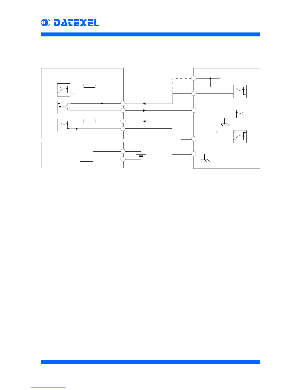
How to connect DA T6000 to PLC
The serial interface of the DA T 6000 series devices is shown hereup. Input and
output signals are optoisolated among analog input and power supply. The
DA T A signal circuit is powered directly with the ENABLE signal voltage. Without
the ENABLE signal, the data output is disabled. The ENABLE input
(terminal N) can be connected directly to the supply voltage, leaving available a
PLC output port; in this case the data output is always enabled. Using the
ENABLE signal, the CLK signal can be always active, because when ENABLE
signal is off, the microprocessor ignores the clock signal, stopping the data
sending; by this way, it is possible to connect many devices in multidrop
connection, using few PLC I/O ports.
The power supply of the DAT6000 is isolated from the serial interface so that
the auxiliary supply of the PLC can be used to power it.
DAT 6000
4
PRELIMINARY
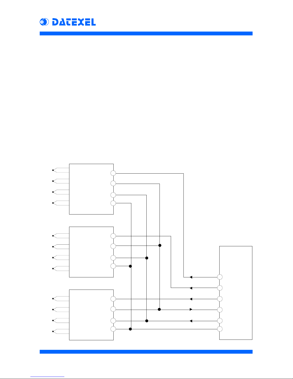
Multidrop connection
The CLK input and the DA TA output of the DA T6000 devices are actives only
when the ENABLE signal is on. Consequently It is possible to connect all the
DA T A signals to the same PLC digital input and all the CLK signals to the same
PLC digital output. Devices can be activated one by one sending the ENABLE
signal to the selected device only .
As shown in the figure below , using n°3 DA T6000 devices it is possible to read
the value of up to 12 analog sensors using only 4 PLC digital outputs and 1 PLC
digital input. Each new device connected will use only one more PLC digital
output (ENABLE).
Changing the device type, it is possible to create many combinations of analog
inputs (i.e.: 4 Tc inputs on the first device, 4 mA inputs on the second device
and 2 Potentiometer inputs on the third device), without to change the wiring to
the PLC and the software data reading procedure.
P
M
O
ENABLE 3
DATA
CLK
GND
DAT6021
N° 1
P
M
O
P
M
O
N
N
N
ENABLE 2
ENABLE 1
Digital out
Digital out
Digital out
Digital in
Digital out
Ground
Tc 1
Tc 2
Tc 3
Tc 4
Tc 5
Tc 6
Tc 7
Tc 8
Tc 9
Tc 10
Tc 11
Tc 12
DAT6021
N° 2
DAT6021
N° 3
PLC
Digital I/O
DAT 6000
5
PRELIMINARY
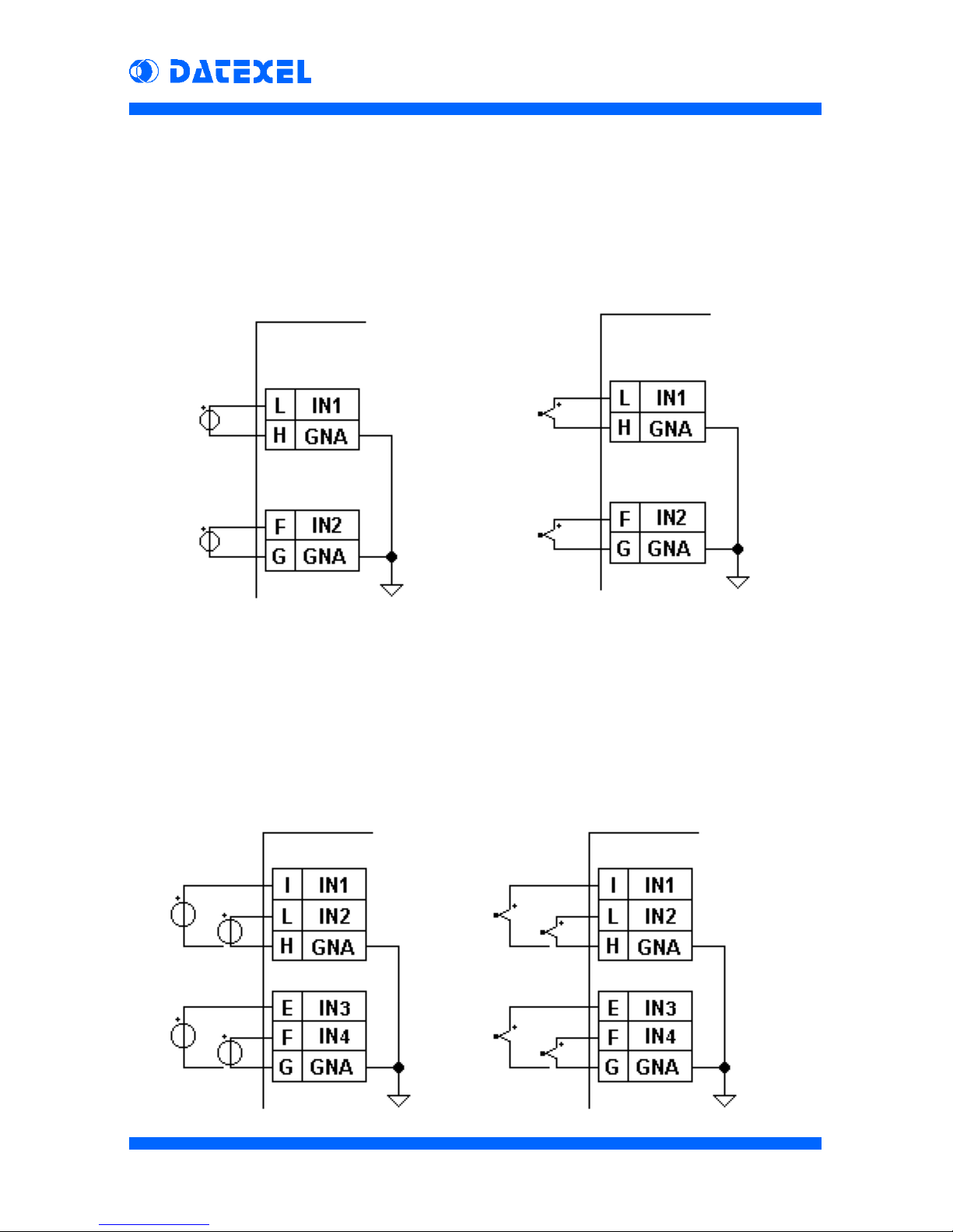
Analog Inputs connection
Tc
wiring
mV
wiring
DAT 6011
Tc
wiring
mV
wiring
DAT 6021
DAT 6000
6
PRELIMINARY
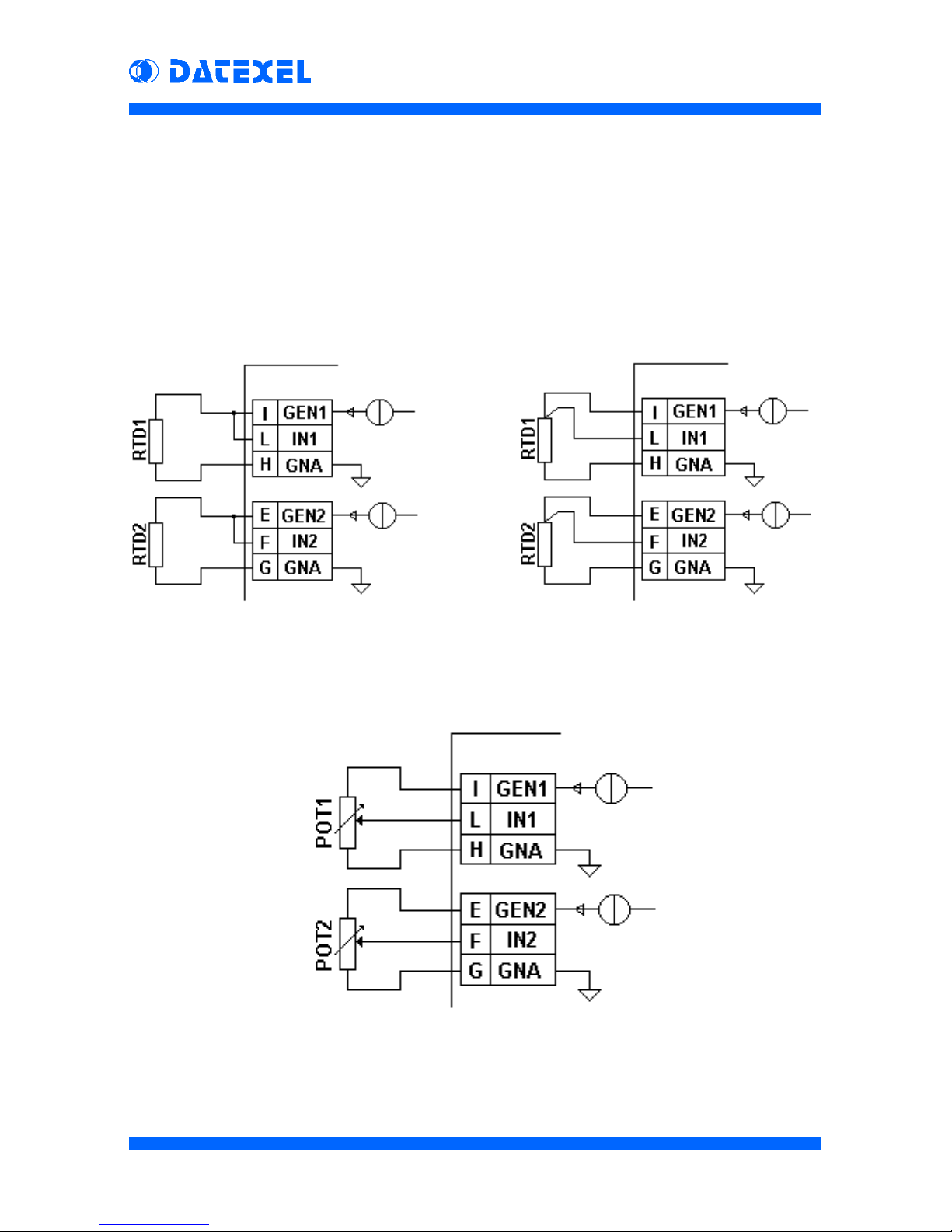
3 wires RTD/Res
wiring
2 wires RTD/Res
wiring
DAT 6012
Potentiometer
wiring
 Loading...