

Datexel DAT 4530 User Manual

DAT 4530
DAT 4530
Universal isolated converter
configurable by Dip-Switch or PC
double output & trip amplifier
TECHNICAL SPECIFICATIONS (Typical @ 25 °C and in nominal conditions)
Line resistance influence (1)
TC, mV <=0.8 uV/Ohm
RTD 3w (50W max balanced) 0.05%/W
RTD 4w (100W max balanced) 0.005%/W
Linearity (1)
TC, RTD ± 0.1 % f.s.
mV, V, mA ± 0.05 % f.s.
Thermal drift (1)
Full scale ± 0.01% / °C
CJC ± 0.01% / °C
RTD excitation current
RTD, Res 400 uA
CJC Comp. ± 0.5°C
Input impedance
TC, mV >= 10 MW
mA ~22 W
Aux. Voltage >18V @ 20mA
ALARM TRIP (SSR)
Contact SPST
Max Load (resistive) :
Voltage 48 Vdc / 30 Vac
Current 0.4 A
Aux. Voltage >12V @ 20mA
FEATURES
- Universal configurable input for:
mV, Tc, RTD, Res, Potentiometer, V and mA
- Two outputs configurable in current or voltage
- Trip alarm
- Configurable by dip-switch or PC
- High accuracy
- On-field reconfigurable
- Galvanic isolation among all the ways
- UL / CE mark
- Suitable for DIN rail mounting in compliance
with EN-50022 and EN-50035
GENERAL DESCRIPTION
The universal isolated converter DAT 4530 is able to measure and linearise voltage, current and resistance signals, potentiometers and the standard
thermocouples and RTDs with, if required, the cold junction compensation, the wires compensation. For mV, V and mA input it is possible to set an
option for the fast sampling (option HS) or to extract the square root of the measured signal (option SQRT). In function of programming, the measured
values are converted in a current or voltage signal on the two outputs. Moreover an output contact is available as trip alarm.
By dip-switches accessible opening the window on the side of the enclosure, it is possible to select the input type and range and the output type without
recalibrate the device.
By Personal Computer the user can set the two outputs with independent settings, the parameters of the Trip Alarm and the optional parameters for his
own necessity;
The galvanic isolation between input, outputs and power supply eliminates the effects of all ground loops eventually existing and allows the use of the
converter in heavy environmental conditions found in industrial applications. The device guarantees high accuracy and performances stability both
versus time and temperature.
The DAT 4530 is in compliance with the Directive UL 61010-1 for US market and with the Directive CSA C22.2 No 61010-1 for the Canadian market.
It is housed in a plastic enclosure of 12.5 mm thickness suitable for DIN rail mounting in compliance with EN-50022 and EN-50035 standards.
USER INSTRUCTIONS
The connections must be made as shown in the section "Connections".It is possible to configure the converter on field by dip-switch or Personal
Computer as shown in the section “ Programming ". The configuration by dip-switches can be made also if the device is powered (note: after the
configuration the device takes some seconds to provide the right output measure ).
Output type Min Max Min Span
Output resolution
Current 7 uA
Voltage 4 mV
Burn-out values
Max. output value 22 mA or 11 V
Min. output value 0 mA or -0.6 V
Current 0 mA 20 mA 4 mA
Voltage 0 V 10 V 1 V
Response time (10÷ 90%) about 400 ms
100 ms (option HS)
Output load Resistance - Rload
Current output < 500 W
Voltage output > 10 KW
Short circuit current 30 mA max.
OUTPUT (2 CHANNELS)
MECHANICAL SPECIFICATIONS
Material Self-extinguish plastic
IP Code IP20
Wiring wires with diameter
0.8÷2.1 mm2 /AWG 14-18
Tightening Torque 0.8 N m
Mounting in compliance with DIN
rail standard EN-50022
and EN-50035
Weight about 90 g.
Power supply voltage 20 .. 30 Vdc
Reverse polarity protection 60 Vdc max
Current consumption
Current output 90 mA max.
Voltage output 30 mA max.
ISOLATION
Among all the ways 1500 Vac,
50 Hz, 1 min
POWER SUPPLY
Input type Min Max Span min
Accuracy (1)
mV, TC the higher of ±0.1% and ±12 uV
RTD the higher of ±0.1% and ±0.2°C
Res. the higher of ±0.1% and ±0.15
Potentiometer ± 0.05 % f.s.
Voltage the higher of ±0.1% and ± 2 mV
mA the higher of ±0.1% and ± 6 uA
mV, V, mA ± 0.5 % f.s (opt. HS)
RTD (2, 3, 4 wires)
Pt100 -200°C 850°C 50°C
Pt1000 -85°C 185°C 30°C
Ni100 -60°C 180°C 50°C
Ni1000 -60°C 150°C 30°C
RES. (2, 3, 4 wires) 0 W 500 W 50 W
0 W 2000 W 50 W
INPUT
Voltage -10 V 10 V 1 V
TC (CJC int./ext.)
J -200°C 1200°C 100°C
K -200°C 1300°C 100°C
S 0°C 1750°C 400°C
R 0°C 1750°C 400°C
B 0°C 1850°C 400°C
E -200°C 1000°C 100°C
T -200°C 400°C 100°C
N -200°C 1300°C 100°C
Voltage
mV -100 mV +90 mV 5 mV
mV -100 mV +200 mV 10 mV
mV -100 mV +800 mV 20 mV
(1) referred to the input Span (difference between max. and min.)
Pot. (Rnom.< 50KW) 0 % 100 % 10 %
Current 0 mA 20 mA 1 mA
RTD/RES
V
mA
V
mA
TcmV
mA
V
Pot
Alarm
DC SUPPLY
+
-
ENVIRONMENTAL CONDITIONS
Operative Temperature -20°C .. +60°C
UL Operative Temperature -10°C .. +60°C
Storage Temperature -40°C.. +85°C
Humidity (not condensed) 0 .. 90 %
Maximum Altitude 2000 m
Installation Indoor
Category of installation II
Pollution Degree 2
CERTIFICATIONS
EMC ( for industrial environments)
Immunity EN 61000-6-2
Emission EN 61000-6-4
UL
US Standard UL 61010-1
Canadian Standard CSA C22.2 No 61010-1
CCN NRAQ/NRAQ7
Typology Open Type device
Classification Industrial Control
Equipment
File Number E352854
4-20mA Current Splitter
Phone: +1 561 779 5660 E-mail : Info@datexel.com - Web Site www.datexel.com
87654321
87654321
SW1
SW2
Input type
Out B
Full scale
Zero
OFF
ON
- Input type Pt100
- Option 3 wires
- Out A 4-20 mA
- Out B 0-10 V
- Full scale 200 °C
- Zero -50 °C
EX. of configuration
SW1 =
SW2 =
SW3 =
4321
SW3
Out AOpt
CONFIGURATION BY PC
By software DATESOFT it is possible to:
- set the default programming of the device;
- program the options not available with the dip-switch;
(burn-out level, CJC offset, trip alarm settings, fast sampling, etc...);
- read, in real time, the input and output measures;
- follow the dip-switches configuration wizard.
To configure the device follow the next steps:
1) Power-on the device.
2) Open the protection plastic label on the front of the device.
3) Connect the interface PRODAT to the PC (COM port)
and to the device (PGRM connector).
4) Open DATESOFT.
5) Select the COM port in use.
6) Click on “Open COM”.
7) Click on the icon “Program”.
8) Set the programming data.
9) Click on the icon “Write” to send the programming data to the device.
Warning: during these operations the device must always be powered and the TX/RX cable always connected.
For information about DATESOFT refer to the software's user guide.
J1
TX/RX CABLE
PRODAT
COM PORT
P.C.
V+ V-
U
V
PGRM
Plastic label protection
DAT
POWER SUPPLY
UNIT
PROGRAMMING
CONFIGURATION BY DIP-SWITCHES
1) Open the suitable door on the side of the device.
2) Set the input type by the dip-switch SW1 [1..5] (see TAB.1)
3) Set the output A type by the dip-switch SW1 [7..8] and SW2 [1..2] (see TAB.2)
4) Set, if available, the input option by the dip-switch SW1 [6] (see TAB.3)
5) Set the minimum input scale value (Zero) by the dip-switch SW3 [1..4] (see TAB.4)*
6) Set the maximum input value (Full scale) by the dip-switch SW2 [3..8] (see TAB.4)*
NOTE:
- It is also possible to set the dip-switches using the wizard of the
configuration software following the procedure described in the section
”Configuration by PC” until the step 6 and clicking on icon “Switch”.
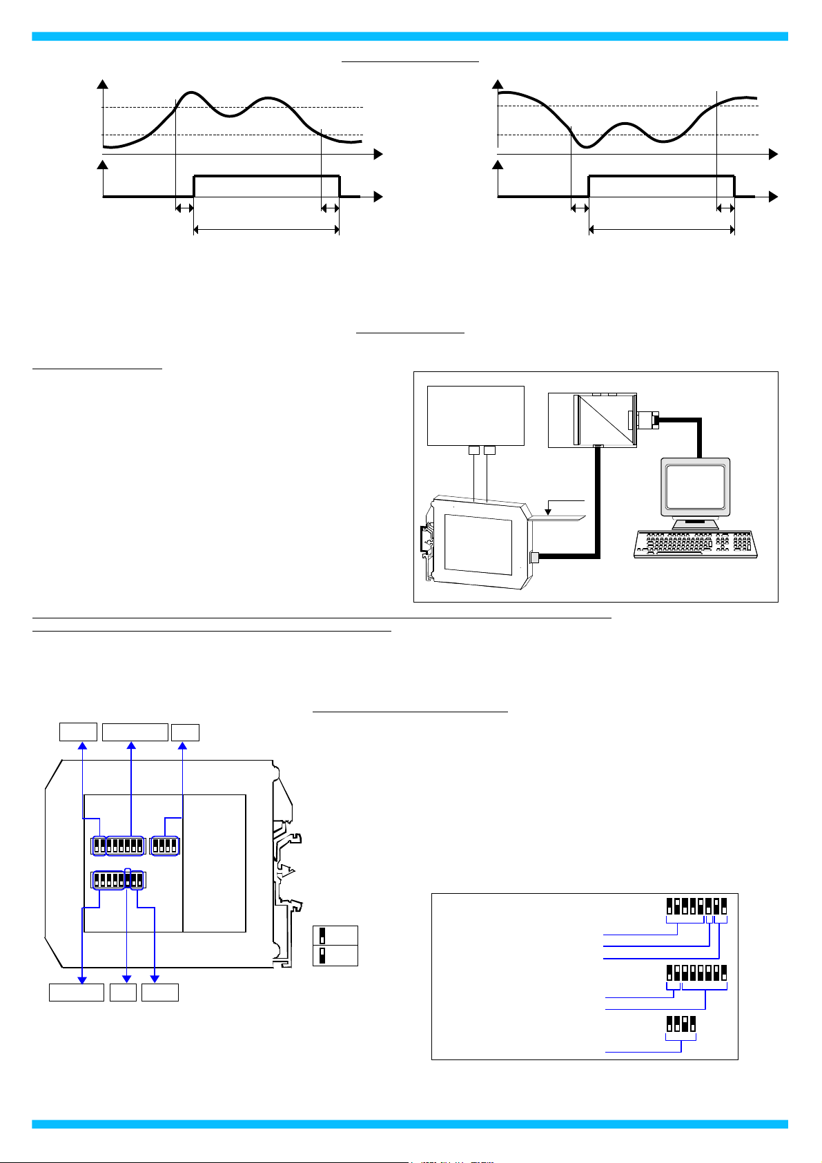
THRESHOLD OPERATION
For the high alarm the relay goes on when the input signal is higher than
the trip level and after the delay time. The relay goes off only when the
input signal is lower than the trip level minus the hysteresis value or when
reaches the minimum value of the input scale and after the delay time.
For the low alarm the relay goes on when the input signal is lower than the
trip level and after the delay time. The relay goes off only when the input
signal is higher than the trip level plus the hysteresis value or when
reaches the maximum value of the input scale and after the delay time.
T(delay) T(delay)
Active relay
Trip level
Trip level - hyst.
T(delay) T(delay)
Active relay
Trip level
Trip level + hyst.
HIGH ALARM THRESHOLD
LOW ALARM THRESHOLD
 Loading...