

Datexel DAT 1111 Installation Instructions Manual

Via monte Nero, 40/B – 21049 TRADATE (VA) ITALY
Phone: +39 (0)331841070 Fax:+39 (0)331841950 - e-mail:datexel@datexel.it - www.datexel.it
Low profile, dip-switch
programmable and linearised
transmitter for Pt100
DAT 1111
DAT 1111
GENERAL DESCRIPTION
The transmitter DAT 1111 is designed to provide on output a 4÷20 mA current loop linearised signal proportional with the temperature characteristic provided
from the Pt100 connected to its input.
It is possible to connect on input both Pt100 3 wires and Pt100 2 wires sensors.
It is possible to program the input range by the 4 way DIP-switches available removing the protection plastic cap located on the top of device (see the section
“Input ranges table”).
The regulation of the zero and full-scale value are made using the ZERO and SPAN potentiometers.
The DAT 1111 is in compliance with the Directive 2004/108/EC on the Electromagnetic Compatibility.
It is housed in a self-extinguish plastic enclosure suitable for DIN B in-head mounting.
Moreover ( by proper mounting kit ) it is possible to mount the DAT 1111 on DIN rail.
FEATURES
- Input from Pt100
- Input scale in °C or °F
- Zero and Span programmable by DIP-switches
- 4÷20 mA current loop linearised output
- Good accuracy and linearity
- EMC compliant – CE mark
- Suitable for DIN B in-head mounting
- Option for DIN rail mounting in compliance with EN 50022 (DIN RAIL Option)
USER INSTRUCTIONS
The transmitter DAT 1111 must be powered by a direct voltage between 10 to 32 V applied to the terminals +V and -V.
The 4÷20 mA output signal is measurable in the power loop as shown in the section “Output/Power supply connections”; Rload is the input impedance of
instruments on the current loop; to obtain a correct measure, the value of Rload will be calculated as function of the power supply value ( see section “ Load
characteristic”).
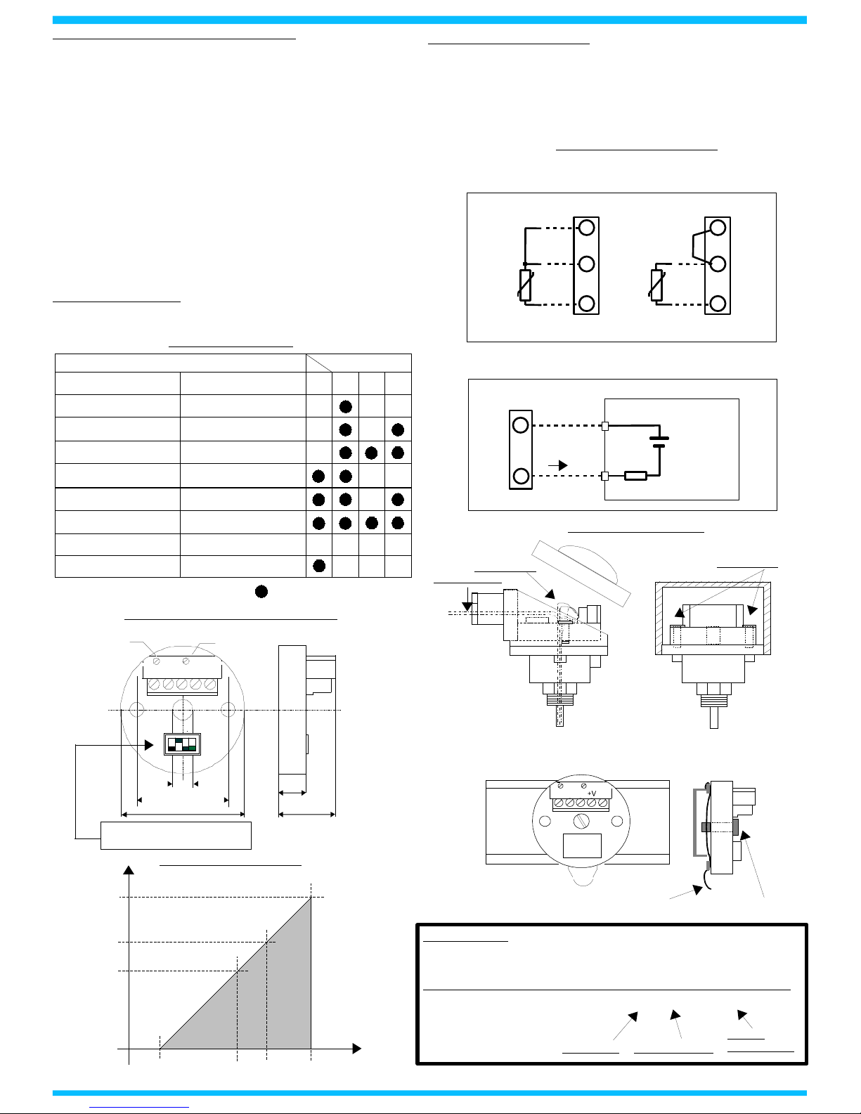
The input connections must be made as shown in the section "Input connections".
The Pt100 three wires must be connected to the terminals 1 and 3, connecting the third wire to the terminal 2.
The Pt100 two wires must be connected to the terminals 1 and 3, connecting the terminal 2 and 3.
The configuration of the input range must be made by DIP-switches. To configure the device refer to the section “Input ranges table”.
Regulate the output value by the ZERO and SPAN regulations.
To calibrate and install the transmitter refer to sections " DAT1111: configuration and calibration" and “Installation Instructions”.
TECHNICAL SPECIFICATIONS (Typical at 25 °C and in nominal conditions)
Input
Sensor type RTD Pt100 in according to IEC 60751
Minimum input Span 50 °C (122 °F)
Zero programmability From -50 °C (-58 °F) up to + 50 °C (122 °F)
Span programmability From 50 °C (122 °F) up to 650 °C (1202 °F)
Excitation current 1 mA typ.
Line resistance influence 0.05 % of f.s./ohm (100 ohm max. balanced per wire)
Output
Output type 4 ÷ 20 mA on current loop
Sensor interruption signalling Positive out of scale (> 20 mA)
Maximum output signal 35 mA
Load resistance (Rload) see section “Load characteristic”
Response time (from 10 to 90 % of f.s.) 300 ms
Warm-up time 3 min.
Performances
Calibration error ± 0.1 % of f.s.
Linearity error (*) ± 0.15 % of f.s.
Thermal drift 0.03 % of f.s./°C
Power supply voltage (**) 10÷32 Vdc
Electromagnetic Compatibility (EMC)
( for industrial environments ) Immunity: EN 61000-6-2; Emission : EN 61000-6-4.
Operating Temperature -20 ÷ 70 °C
Storage Temperature -40 ÷ 85 °C
Humidity (not condensed) 0 ÷ 90%
Weight about 35 g.
(*)inclusive of hysteresis, linearisation error and power supply voltage variation
(**)internally protected against reverse polarity.
Datexel s.r.l. reserves its rights to modify the characteristics of its products without warning at any time .
DAT 1111: CONFIGURATION AND CALIBRATION
1) Calculate the difference between the full-scale and the begin scale values
(Span).
2) Refer to the “Input range table” and determine in the column " SPAN "
where the calculated value is included. Determine in the column “ZERO”,
the range of value where the zero scale value is included. In the line
obtained with the combination, is shown the DIP-switches configuration.
3) Remove the protection plastic cap.
4) Set the switches as indicated.
5) Connect on input a Pt100 simulator or a fixed resistance value
corresponding to the resistive value provided from the Pt100 sensor at the
selected temperatures.
6) Set the simulator at the minimum temperature or connect a fixed
resistance value corresponding to the zero value.
7) Regulate the output value at 4 mA by the “ZERO” potentiometer .
8) Set the simulator at the maximum temperature or connect a fixed
resistance value corresponding to the span value.
9) Regulate the output value at 20 mA by the “SPAN” potentiometer .
10) Repeat the operation from the step 6 to the step 9 until the output
values are accurate ( typical 3 attempts required ).
Example of configuration: -30/200 °C.
Span => 200°C - (-30°C) = 230°C;
Input switches configuration: Off, Off, Off, Off.
INSTALLATION INSTRUCTIONS
The device DAT 1111 is suitable for direct DIN B in-head mounting. The
transmitter must be fixed inside the probe by the proper kit.
By apposite stirrup, provided on request, it is possible to mount the device
on DIN rail in compliance with EN-50022. It is necessary to install the
device in a place without vibrations; avoid to routing conductors near
power signal cables .
ED.02.07 REV.02
INPUT RANGE TABLE
DAT1111: CONNECTIONS
INPUT CONNECTIONS
POWER SUPPLY/OUTPUT CONNECTIONS
+
-
Rload
Iout
10÷32 Vdc
+
Pt100 3 wires
+V
-V
Pt100 2 wires
Pt100
3
2
1
Pt100
2
3
1
Working
Area
0
1K
700
400
10 18 24 32 V
Ohm
LOAD CHARACTERISTIC
DIMENSIONS (mm) & REGULATIONS
21-V3
ZERO SPAN
DIN rail mounting (DIN RAIL Option)
Fixing screw
Stirrup
HOW TO ORDER
The DAT1111 is provided as requested on the Customer's order.
In case of the configuration is not specified, the parameters must be set by the
user.
The mounting kit for DIN rail is provided only on request with code DIN RAIL.
ORDER CODE EXAMPLE: DAT1111 0÷200 °C/°F – DIN RAIL Option
Input range
Unit of measure
DIN rail
mounting KIT
Fixing screws
DIN B In-head mounting
Sensor cables
4÷20 mA cables
Dip-switches available removing
protection plastic cap
7
4 3
1 7
3 3
Z E R O
S P A N
O N
1
9
= DIP SWITCH : " ON"
SPAN
ZERO
SWITCH
INPUT
1 2
3
4
< 80°C (176°F)
80÷200°C(176÷392°F)
200÷250°C(392÷482°F)
- 50÷50°C(-58÷122°F)
- 50 ÷ -15°C(-58÷5°F)
- 15 ÷ 15°C(5÷59°F)
15 ÷ 50°C(59÷122 °F)
< 80°C (176°F)
< 80°C (176°F)
80÷200°C(176÷392°F)
80÷200°C(176÷392°F)
250÷650°C(482÷1202°F)
- 50÷50°C(-58÷122°F)
- 50 ÷ -15°C(-58÷5°F)
- 15÷ 15°C(5÷59°F)
15 ÷ 50°C(59÷122 °F)
 Loading...