

Page 1

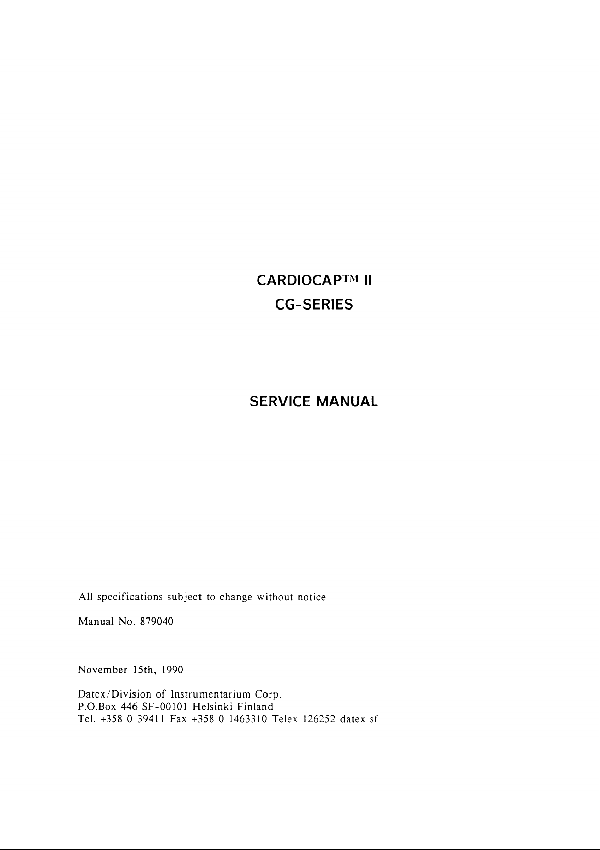
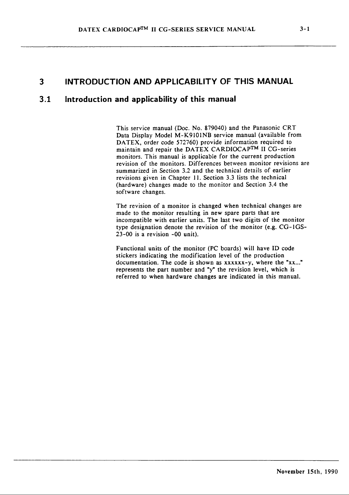
ENTERING
SERVICE
MODE
ON
Allow
Press
When
Select
Unit
Buttons
"S"
preference
to
carry
1,
2,
appears
then
out
startup
3, 4 then
to
top
Left
press
DATEX
Sequence.
press
and
corner
Return
To
Adjust
CARDIOCAP
hold
Return
of
screen,
to
Monitor
Date,
to
Monitor
Press
button
button.
Time
11
button.
4
Press
and
hold
Mark/Reset
button
and
turn
unit
on
Page 2
CARDIOCAPTM
CG-SERIES
II
All
specifications
Manual!
November
Datex/Division
P.O.Box
Tel.
No.
15th,
446
+358 0 39411
subject
879040
1990
of
SF-00101
Fax
to
change
Instrumentarium
Helsinki
+358 0 1463310
SERVICE
without
Corp.
Finland
Telex
MANUAL
notice
126252
datex
sf
Page 3

DATEX
CARDIOCAP™
II
CG-SERIES
SERVICE
MANUAL
CONTENTS
1.1
1.2
1.3 。 List
U
WARNINGSANDCAUTIONS....................................
INTRODUCTION
3.1
Introduction
3.2
Summary
3.3
Manual
3.3.1
3.3.2
3.4
Software changeS
GENERAL
4.1
Typical
TS
4.2
Technical
SS
4.3.
Principle
4.3.1
4.3.2
4.3.3
4.3.4
4.3.5
44
General
45
VWiringdiagram...............................
4.6
External
4.6.1 | Input/Output
4.6.2
-----ι,,
Table
List
of
contentS.
of
figures
of
tables……… せ トー
of
updates..............
e
AND
APPLICABILITYOFTHISMANUAL..........................
and
applicability
revision
CARDIOCAPTM
Record
DESCRIPTION...............M
of
manual
eee
performance
specifications
of
operatig0n
Principle
Principle
Principle
Principleof
Principle
block
connector
Connectors..................................
of
CO,/N,0
of
O。
of
ECG
NIBPmeasurement.................................................
of
SpO,
diagram
COnfIguratiOns..…..............
specifications............
of
changeS
ii
II
CG-series
updates
of
CARDIOCAPTM
of
CARDIOCAP™
measurement...
measurement
measurement
measurement
.… せ iene
this
carried
iii
KRK K Rano
KP
manual...
erener
service
KPP
EK
is.
.….....................................................
eee
manual
out...
re
II
CG-SERIES
PRK R KRKA
eee
AKKO
I
CG-SERIES
1-1
ss
n n
nn nn
ekk
1-1
1-5
1-8
2-1
3-1
3-1
sner
ennen
nerne
nere
enge
3-3
3-4
changes.....................
3-4
3-5
3-6
ーー
4-1
KKK K OKO
KP
OPOP
нии
ener
Kn P PAP PAE E OKA
eemrenerer
renere
nn
elena
reeks
ne
eee
eee
e
nn
4-1
4-7
4-11
4-11
4-12
4-12
4-13
4-14
4-18
4-20
eee.
erre
errar
re
eeenseannnne
vee
seiner
4-21
4-21
4-21
DETAILED
5.1
Gas
5.2
CO。/N。O
5.2.1
52.2
5.2.3.
5.2.4
5.2.5
DESCRIPTION
sampling
system...............
measurements
Introduction...
SS
Preamplifier
CO,/N,O
O,
measurement
OF
MODULES
ieri
erer
eee
board
measuring
board...
iii
eee
eee
ーー
Rea e eee n 5-9
a
Renate
iii
v
1.
5-1
5-1
5-9
5-9
5-13
5-15
5-20
Page 4
DATEX
WwW
¡JACA
a
uu
IPT
Mm
un
NIBP
5.5.1
5.5.2
5.5.3 。 NIBP
55.4
5.5.5 。 NIBP
5.5.6
5.5.7
SPO,
5.6.1
5.6.2
5.6.3
5.7
CPU _ board
5.8
Video
5.9
Power
5.10
Motherboard.....................................
5.11
Keyboard...
5.12
Loudspeaker
5.13
Internal
CARDIOCAP™
(Invasive-
measurement...
NIBP
Pneumatic
Safety
Twin
Blood
measurement
SpO;,
SpO。
SpO,
control
Supply
connector
Pleth-Temperature)
board
air
valve
tubing
hose
pressure
measuring
processor
connector
board
board
einen
unit
II
CG-SERIES
board… せ ………………………… ス ーー
SERVICE
MANUAL
нии
ина
eee
unit
pumD
iii
ii
i
cuff...............................,..............
ieee
eee
board
board
I/O
board...
站
usines
.Ne
erer
configurations...
een
eee
ener
eee
iii
nens erne
eeeee
トー に ーー
erne
naha
ee
eeee
eee
ининнининини
κανε
κανα
εν
nerne
n
kn
ena o een ken n ké
eee
eee
nn
ennen
enes
елииншннния
n
nn
1-2
SERVICE
6.1
6.2
6.3
AND
TROUBLESHOOTING
General
Disassemblyandreassembiy....................................
Troubleshooting
6.3.1
¡A
6.3.3
6.3.4
6.3.5
6.3.6
6.3.7
6.3.8
6.3.9
6.3.10
6.3.11
6.3.12
service
Monitor
Y
Troubleshooting
Gas
Gasmeasurementtroubleshooting................................................
О.
ECG
IPT
NIBP
SpO,
SpO,
CPU
6.3.12.1
information
start-up
AAN
sampling
system
measurement
board
board
troubleshooting
troubleshooting
board
troubleshooting
..................
sequenoe
in
general...
troubleshooting
eee
enem.
troubleshooting..….........................................
eee
eue
measuringelectronicstroubleshooting..................................
processor
board
Instructions
board
troubleshooting...................
troubleshooting
after
replacing
eee
the
eee
eee
software
emen
or
acena
ec
renere
ee
ーーーーー…
re
CPU
Page 5
DATEX
CARDIOCAPTM
II
CG-SERIES
SERVICE
MANUAL
1-3
6.3.13
6.3.14
6.3.15
6.3.16
6.4
Service
ADJUSTMENTS
7.1
Adjustments
7.2
Gas
73
CO,
7.3.1
7.3.2
7.3.3
7.3.4
7.3.5
7.4
Oxygen
7.4.1
7.4.2
7.43
7.4.4
7.5
ECG
7.6
IPT
7.7
NIBP
7.8
SpO,
7,9:
CPU
Video
Power
Motherboard/Keyboardtroubleshooting..................................
Loudspeakertroubleshooting..................................
sampling
and
Zeroadjustmenis..................................
Gain
Reference
Temperature
Pressure
oOffsetlzero)adjustment..................
Gain
Temperature
Frequency
board
board
board
processor
board
mode
N。O
control
supply
een
after
system
measurement
adjustments
board
board
component
adjustment
voltage
adjustments..............
compensation
measurement
measurement
adjustment
adjustments.................................................
compensation
adjustment
AdjUStMent..
adjustment.…..........
adjustment
board
eee
adjustment..….................................................
adjustment
troubleshooting
troubleshooting..….............................................
replacements
adjustments
ννεωνο
νο
νετ
εεεκωνωκκκεεεεεεκνε
i
<<we
sr
serene
τετ
ετεκ
renerne
εκ
ετεκ
eee
κεετεε
εκατ
ани
adjustments
offset
adjustment
issues
and
ooo
ии
eee
..................................,...….
gain
adjustments
eee
eee
eee
enine
........................
eeeeeeeeeeeen
ии,
цитяшиинининнннье
ии
лиан
cerises
ens
ετεκ
rss
i
εεττ
nere
ss
εν
εαν
7-14
7-16
7-17
7-18
7-19
7-19
6-24
6-2
6-26
6-26
6-27
7-1
7-
1
7-2
7-6
7-6
7-7
7-10
7-10
7-12
7-13
7-13
7-13
7-14
FUNCTIONAL
8.1
Preoperative
8.2
Checks
8.3
Preventive
SPARE
9.1
9.2
12
APPENDİCES...............................
A
B
ο
Spare
Service
COMPUTER
CCP-104
FIELD
CHECK
check
after
component
maintenance
μμ...”
PartS
eee
accessories...
OUTPUT
GRAPHICS
list...
iene
iii
eren
PRINTER
PROCEDURE
replacements
check
list...
dus
eee
ie
eee
ーーーーー……
eee
eee
nene
enne
none
nana n 8-6
8-1
8-1
8-3
9-1
9-1
9-4
10-1
10-1
10-6
Page 6
DATEX
CCK
-104
С.1
GENERAL
C.1.1
Specifications
C.1.2
Principle
C.1.3
General
С.1.4
Connector
C.2
DETAILED
C2.IKeyboard...........................
C.2.2
Control
C.3
SERVICE
C.3.1
Disassembly
C.3.2
Generaltroubleshooting.............................
C.3.3
Keyboard
C.3.3.1
C.3.4
Contro!
C.3.5
Connecting
CARDIOCAPTM
KEYBOARD
DESCRIPTITON
.......
of
operation...................
block
diagram
configurations
DESCRIPTION
board
eee
AND
TROUBLESHOOTING
and
troubleshooting
Keyboard
board
troubleshooting
cable
II
ui
e
issu
OF
MODULES
erener
reassembiy
test
mode
ie.
...........
troubleshooting
CG-SERIES
i
ee
ie
ee
een
SERVICE
een
MANUAL
ke
kk
kk
ῄᾗὧᾗὖὖ----Ἄ-Ἂ-Ἂ-
anar
eee
rei
rn
nono
ere
ennen
nree
no
nnnananos
nn
nere
ne
sneen
κκ
κκ
τν
10-7
10-7
10-7
10-7
10-9
10-10
10-11
10-11
10-11
10-13
10-13
10-13
10-14
10-14
10-15
10-15
C.4
SPARE PARTS
πι
υυυυ------Ἂ-
10-20
Page 7
DATEX
List
of
Figures 니 니 니 니 니 아 미 미 나 디 미 이 아 미 이 미 미 미 이 마 리 아 마 미 이 마
4.1.
CO3/N70
4.2
Absorption
and
near-infrared
4.3
Absorption
4.4
Finger
4.5
General
46
”Wiring
CARDIOCAP™
gas
coefficients
of
clamp
block
diagram
JI
CG-SERIES
absorption
spectra...............
of
oxy-
iii
and
regiOnSs.................
infrared
probe
diagramn
.vt
light
parts
.pe
in
layout
the
and
SERVICE
마 아 마 마 아 이
deoxy-hemogiobin
finger
schematic
diagrarm.……… せ ーー…・
MANUAL
아 마 마 아 아
아 마 이 아 아 아 아 아 아 아 아 아 아 아 마 다 아 이 PAGE
in
the
red
тии
n
en
nnné
1-5
4-11
4-15
4-16
4-17
4-19
4-20
5.1
Gas
sampling
5.2
Gas
sampling
5.3
CO,J/N,O
っ
>.4 。 Photometer
5.5
Synchronizing
(modification
5.5а
Synchronizing
measuringsystemblockdiagram..............................
(modificatilonlevel
5.6 | Preamplifier
5.7
5.8
5.9
CO,/N,0
CO,/N,O
schematic
O,
measurement
measuring
measuring
diagram
system
system
board
level 6 and
board
board
schematic
layout
parts
parts
Tand
parts
board
board
diagram
(modificationlevel
layout
ljower)
layout
and
.Ne
and
schematic
schematic
higher)...........................................
layout
and
parts
Iayout
timing
schematic
diagram
iii
principle.................
eee
0000000000000
6and
diagram
diagram
diagram
iii
and
onen
een
nee
nenene
5-4
higher)...............................
eee
ARA R R
ARA
KARA
RA n ete
5-5
5-10
5-11
5
.…… せ …
инииитьниинииния
2
5.10
5.11
5.12
ECG
ECG
(board
IPT
board
board
board
block
parts
modification
block
diagraM.....comoooononnnnnnncnnononesannonncnronanocnonoracnanannnononanacnnnnnrniracaneonaness
layout
diagram
and
schematic
level ! and
(CS,2CS,2G,2GS)
diagram
higher}...
no
errar
oné
Page 8
DATEX
IPT
5.13
5.14
5.15
5.16
5.17
5.18
5.19
IPT
(CS,
IPT
IPT
IPT
(1G,
Block
NIBP
(part
board
connector
board
board
connector
2CS,
IGS)
Diagram
board
parts
CE
block
parts
parts
layout
board
CA
diagram
layout
board
of
NIBP
layout
0/0
CARDIOCAPTM
(CS,
2CS,
and
IPT
(1G,1GS)
(1G,1GS)
and
IPT
System
and
iii
II
2G,
board
schematic
.ee
board
schematic
schematic
(USA
CG-SERIES
2GS)
ee
VEersion)................
diagram
SERVICE
diagrams
diagrams
ーーーーー
MANUAL
esse
5-28
5-29
5-30
5-31
O
нненниниция
5-32
5-40
5-4]
1-6
5.19a
5.20
5.20a
5.21
5.22
5.22a
5.23
5.23a
NIBP
(part
NIBP
NIBP
board
1)
(board
board
board
parts
layout
modification
schematic
schematic
(boardmodificationlevel
SpO,
SpO,
diagram
SpO,
diagram
SpO,
SpO,
(part
measuring
measuring
(Dart
measuring
(part
measuring
IS
measuring
2)
(board
board
board
1)…
せ
board
1)
(board
board
ii
board
modification
and
schematic
level 5 and
diagram
diagram
(part
(part
diagram
higher)...
2).................................
iii
es
2)
Sandhigher)........................................
block
parts
parts
signal
signal
diagram...................
layout,
layout,
modification
waveforms
waveforms
level 6 and
timing
timing
diagram
diagram
level 6 and
and
and
higher)
schematic
schematic
ii
and
schematic
and
schematic
higher).….……………………………………………………・
diagram
diagram
cccccccsessscccesscesevevers
5-4la
5-42a
essens
ーー
5-49a
5-50a
5-42
5-48
5-49
5-50
5.24
5.25
5.26
SpO,
SpO,
SpO。
processor
processor
boards
configuratOn
boardblockdiagram................................
boardpartslayoutandschematicdiagram..................................
eee
ee
5-52
5-53
5-54
Page 9
DATEX
5.27
SpO,
connector
CPU
5.28
5.29
5.30
5.31
5.32
boardblockdiagram........................
CPU
board
CPU
board
Video
Video
E
5.33
Power
CARDIOCAPTM
parts
jumper
control
control
supply
I/O
layout and
board
board
board
II
board
configuratiOn
block
parts
parts
schematic
diagram
layout,
eee
block
diagram......................
CG-SERIES
layout
and
diagram......................................
timing
SERVICE
schematic
eee
diagram
MANUAL
diagram............................
トト
and
トト
ストー
トット
schematic
ーー
スレ
eeneeeeeeeeaeeeeeneseeseseeseeaaia
0
εναν
ピー
レト
ピピ
ーー
denn eneret
1-7
5-55
5-59
5-60
5-61
5-63
5-64
5-66
5.34
Transformerdiağram....................................
5.35
5.36
Power
Power
supply
supply
board
board
parts
signal
layout
and
waveforms
schematic
and
schematic
diagram
diagram
(part
A
5.37
Mother
5.38
Keyboard
5.39
Loudspeaker
6.1
Gas
7.1
Gas
7.2
Adjustment
7.3
O,measuringunitadjustments............................................
9.1
Exploded
board
parts
sampling
sampling
pictures
parts
layout
unit
parts
system
system
trimmers
of
layout
and
schematic
and
schematic
layout
troubleshooting
adjustment
location
the
and
monitor...
diagram..…..............................
diagram.....................
schematic
Chart.........v.
Chart.................
diagram...........
ice
ricer
verrei
eee
cirie
O A RKK
PP
KARA
AP Ra
een
5-67
1)........................
иене
i
ii
eee
еиненнини
εεττ
τε εν
5-68
5-69
5-71
5-72
5-73
6-10
2
7-15
>
7-4
7-7
9-6
9.2
9.3
C.1
ECG
and
Pneumatic
Example
CCP-104
IPT
boards
unit
of
anesthesia
printer...............................
assemblY..................
parts
layOUt...........
ὐὐ------
record
produced
with
eee
CCK-104
eee
keyboard
eee
and
っ
9-7
9-8
12-7
Page 10

DATEX
C.2
CCK
-104
block
C.3
C4
C.5
C.6
C.7
C.8
Control
Generaltroubleshooting
Keyboard
Соп!то!
Control
Connecting
board
partslayoutandschematicdiagram...........................»...»..».....
Боаг4
board
cable
CARDIOCAPTM
diagram
block
diagram..............
chart..................................
поцЫезБоойпв
parts
layout
schematic
II
CG-SERIES
сВаги.......
and
schematic
diagram............
или
diagram.................
iene
eee
нина
SERVICE
rei
sise
MANUAL
neces
ーーーーーー
ーー
1-8
12-9
12-11
12-12
12-15
12-16
12-17
12-18
C.9
Exploded
view
of
CCK-104
Keyboard
ienes
12-20
Page 11
DATEX
List
of 工 ables
4.1
Pin
order
4.2
Pin
order
4.3.
Pin
order
4.4
Pin
order
4.5.
Pin
order
4.6
Pin
order
seen
of
of
of
of
of
of
CARDIOCAP™
the
ECG
the
invasive
the
invasive
the
pulse
the
SERIAL
the
AUX
II
CG-SERIES
SERVICE
MANUAL
connector.…..................................
pressure
pressure
oximeter
&
I/O
connector........................
probe
ANALOG
connector
connector
connector
(PRESSURE
(PRESSURE
(SpOsz)
<
connector..................
1)...........
2)...............
i
PAGE
nene
nn
.……………---….
onen
eno
nn
1-9
4-2]
4-22
4-22
4-22
4-23
4-24
5.1
5.2
5.3
5.4
5.5
5.6
5.7
5.8.
5.9
5.10
SAG
Tube
lengths
Other
Video
Main
CO;/N,0
NIBP
Power
sampling
control
CPU
board
supply
Keyboard
Power
Mother
supply
System
board
board
measuring
(X1) - Mother
(X1) - Mother
board
(X1) - Mother
board - Mother
board
test
connector
parts
(X1) - Mother
board
board
(X10) - Mother
(X1) - Mother
board
board
(X8)
board
(X13)........
линии
инет
ii
board
(X4).........
(X1)..........
(X2)........
board
eee
board
(X5)........
eterno
(X0)
erre
линии
ини
ини
(X3)..............................
iii
υ----------
щинининнинннь
creer
ーーーーーーーーーーー
arena
raras
ana
nn
4-25
5-74
5-75
5-76
5-77
2
5-78
5-79
5-79
5-79
5-6
5-7
5.11
Front
5.12
SpO,
5.13
SpO,
514
ECGboard-Motherboard(X193)................................
panel
SpO,
connector - SpO,
measuring
processorboard(X1)
board
measuring
(X2) - SpO,
-SpO,connector1/Oboard.......................................
connector
board
I/O
(X1)...............
board
„er
eee
eee
5-80
5-80
5-81
5-82
Page 12
DATEX
IPT
board - Mother
CARDIOCATTM
board
(入
10)
use
II
CG-SERIES
SERVICE
MANUAL
5-82
Video
Power
Power
Power
Power
NIBP
board
O,
measuring
Gas
zero
Pressure
Power
Error
messages
control
supply
supply
supply
supply
board
board
board
board
board
(X2) — NIBP
unit - Mother
valve - Mother
valve - Mother
supply
board
(X2) - Videounitmainpcboard(Xl3).......................
(X1) - Line
(X3) - Fan...
(X6) - Video
(X8) - Loudspeaker
Pump
board
board
(X2) - IR
eee
transformer...............
unit
main
pc
board
board
(X9)
(X I 1)
(XT)
lamp
<<<<©©<<zc<<<crzr94
enr
линии
sieurs
ii
se
mmm
m
лилии
ss
onen
лилии,
eee
ené n n
5-82
5-83
5-83
5-83
5-83
5-84
5-84
5-84
5-85
5-85
6-5
6.2
General
6.3
Gas
6.4
ECG
6.5
IPT
6.6
NIBP
6.7
SpO,
6.8
Power
71
CO,
7.2
N,Olinearizatlon.........................................
troubleshooting
measurement
board
board
troubleshooting
troubleshooting
board
measuringelectronicstroubleshooting
supply
linearizatlon.....................
troubleshooting
troubleshooting
board
een
chart
chart...
ie
chart.............
eee
Chart
troubleshooting
chart
errei
Chart
ei
eee
eee
rante
chart.....................................
“«ἃὃ.«:
«ὁ«
«κ
een
линия
лининшинини
εκ
αν
6-7
6-11
6-16
6-17
6-18
6-21
6-25
7-8
7-9
Page 13
DATEX
CARDIOCAPTM
II
CG-SERIES
SERVICE
MANUAL
2-1
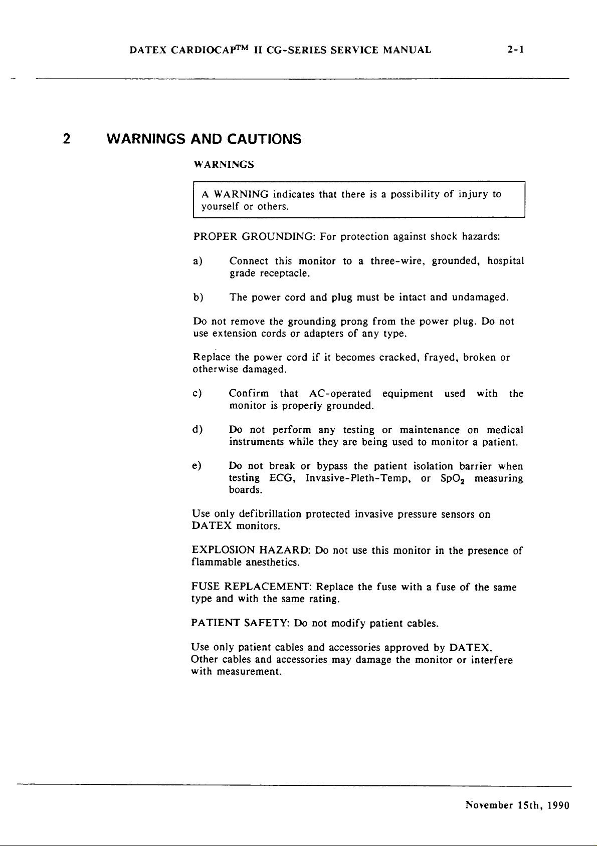
2
WARNINGS
AND
WARNINGS
A
WARNING
yourself
PROPER
a)
b)
Do
not
use
extension
Replace
otherwise
c)
d)
CAUTIONS
indicates
or
others.
GROUNDING:
Connect
grade
The
remove
the
damaged.
Confirm
monitor
Do
instruments
this
receptacle.
power
the
cords
power
that
is
properly
not
perform
that
For
monitor
cord
and
grounding
or
adapters
cord
if
AC-operated
any
while
they
there
is a possibility
protection
to a three-wire,
plug
must
be
prong
it
becomes
grounded.
from
of
any
testing
are
being
type.
cracked,
equipment
or
against
shock
grounded,
intact
the
and
power
frayed,
maintenance
used
to
monitor a patient.
of
injury
hazards:
undamaged.
plug.
broken
used
with
on
to
hospital
Do
not
or
the
medical
e)
Do
testing
boards.
Use
only
DATEX
EXPLOSION
flammable
FUSE
type
REPLACEMENT:
and
PATIENT
Use
only
Other
with
cables
measurement.
not
break
ECG,
defibrillation
monitors.
HAZARD:
anesthetics.
with
the
same
SAFETY:
patient
cables
and
accessories
or
bypass
the
patient
Invasive-Pleth-Temp,
protected
Do
Replace
not
invasive
use
this
the
fuse
rating.
Do
not
modify
and
accessories
may
patient
damage
isolation
pressure
monitor
with a fuse
cables.
approved
the
monitor
or
SpO,
sensors
in
the
by
DATEX.
barrier
measuring
on
presence
of
the
or
interfere
when
of
same
November
15th,
1990
Page 14
DATEX
CARDIOCAP™
II
CG-SERIES
SERVICE
MANUAL
2-2
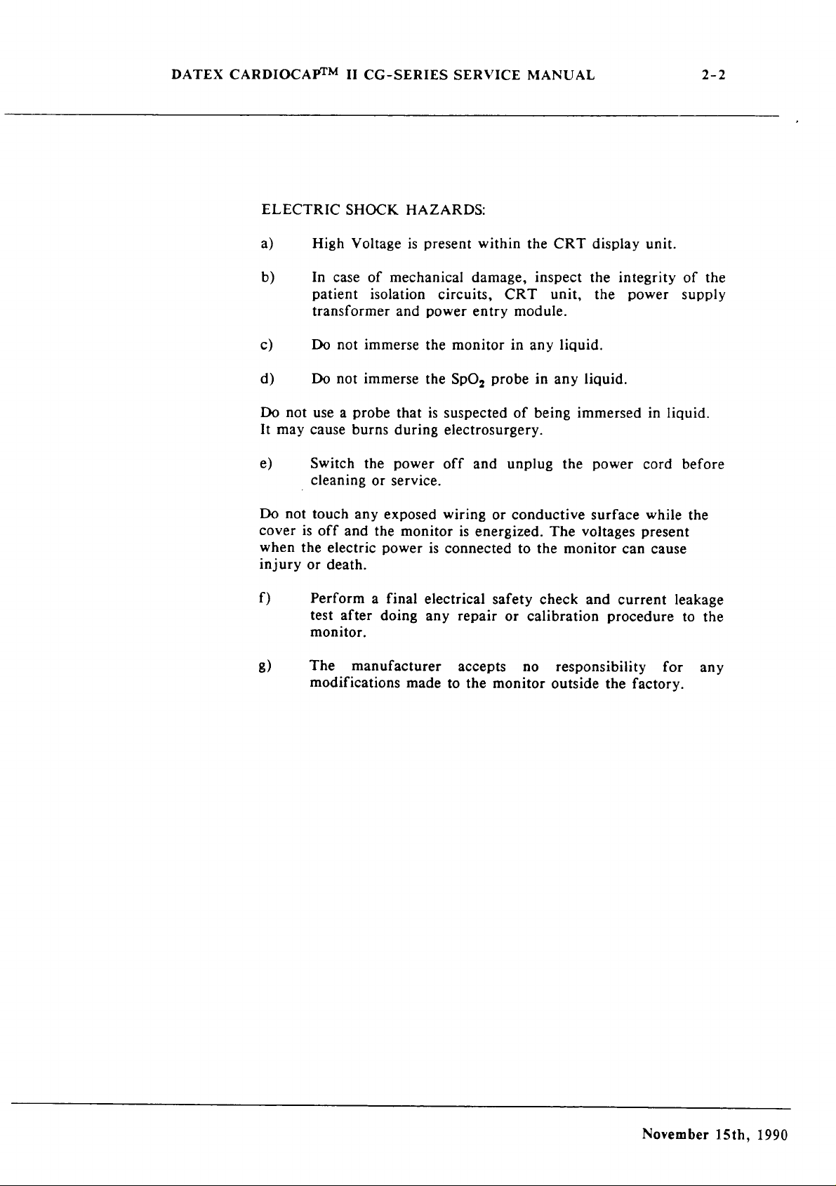
ELECTRIC
a)
b)
c)
d)
Do
not
It
may
e)
,
Do
not
cover
when
the
injury
f)
SHOCK
High
Voltage
In
case
of
mechanical
patient
transformer
Do
Do
use a probe
cause
Switch
cleaning
touch
is
off
electric
or
death.
not
not
burns
and
isolation
immerse
immerse
the
or
service.
any
exposed
the
power
and
that
during
power
monitor
Perform a final
test
after
doing
monitor.
HAZARDS:
is
present
circuits,
power
the
monitor
the
SpO,
is
suspected
electrosurgery.
off
wiring
is
connected
electrical
any
within
damage,
entry
probe
and
or
is
energized.
safety
repair
the
CRT
inspect
CRT
unit,
module.
in
any
in
any
of
being
unplug
conductive
The
to
the
check
or
calibration
display
the
the
liquid.
liquid.
immersed
the
power
surface
voltages
monitor
and
unit.
integrity
power
in
cord
while
present
can
cause
current
procedure
of
the
supply
liquid.
before
the
leakage
to
the
g)
The
manufacturer
modifications
made
accepts
to
the
no
monitor
responsibility
outside
the
factory.
for
any
November
15th,
1990
Page 15

DATEX
CARDIOCAP™
IT
CG-SERIES
SERVICE
MANUAL
2-3
CAUTIONS
A
CAUTION
damage
indicates a condition
or
malfunction.
that
may
lead
to
equipment
a)
b)
c)
Clean
d)
e)
f)
g)
The
tests
and
be
done
by
equipment.
warranty.
Check
monitor
Leave
the
to
space
ventilation.
or
replace
Before
error
the
Switch
external
Do
These
the
use,
messages
Operator’s
the
equipment.
not
use
cleaners
Electrostatic
the
components.
repairs
trained
Unauthorized
rear
panel
AC
mains
behind
fan
filter
allow
monitor
ammonia-,
five
or
deviations
Manual.
off
may
damage
discharge
described
personnel
service
voltage
power
outlet.
the
monitor
regularly.
minutes
before
phenoi-,
the
through
in
with
setting
for
from
making
or
monitor
the
this
manual
proper
may
before
to
warm-up
expected
any
acetone-based
tools
void
connecting
allow
operation.
connections
surface.
PC
boards
should
the
for
and
may
only
and
test
monitor
the
proper
note
any
See
with
cleaners.
damage
Before
wrist
Handie
static
h)
The
larger
operating
internal
i)
replacing
Strap.
all
containers
Connect
scavenging
diameter
than
pressure
damage
The
to 3 times
and
PC
boards
when
sample
of
the
that
of
may
diameter
system
sample
within
larger
overpressurization
internal
damage
repairing
by their
transporting
gas
outlet
to
prevent
scavenging
out
the
monitor.
result.
of
the
calibration
than
of
the
of
the
PC
boards,
wear a static
non-conductive
them.
on
the
monitor’s
room
air
system
tubing
tubing
to
avoid
Inaccurate
gas
delivery
that
of
the
sensors.
monitor
Inaccurate
may
result.
edges
pollution.
must
changing
readings
sampling
control
and
use
anti-
rear
panel
to
be 2 to 3 times
the
or
tube
must
be
2
line
to
avoid
calibration
November
or
15th,
1990
Page 16
DATEX
CARDIOCAP™
II
CG-SERIES
SERVICE
MANUAL
2-4
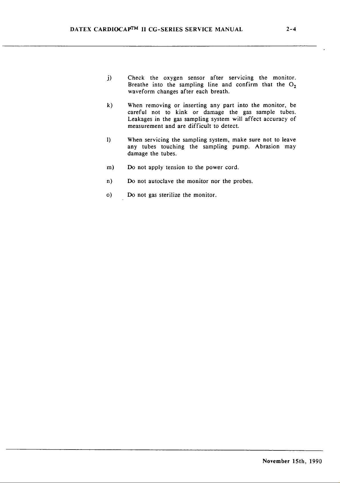
1)
k)
1)
m)
n)
ο)
Check
Breathe
waveform
When
careful
Leakages
the
into
changes
removing
not
in
measurement
When
any
damage
Do
Do
Do
servicing
tubes
the
not
apply
not
autoclave
not
gas
oxygen
the
sampling
or
to
kink
the
gas
and
are
the
touching
tubes.
tension
the
sterilize
sensor
after
each
inserting
or
sampling
difficult
sampling
the
to
the
monitor
the
monitor.
after
line
breath.
any
damage
system
to
detect.
system,
sampling
power
nor
servicing
and
confirm
part
into
the
will
make
pump.
cord.
the
probes.
the
gas
affect
sure
Abrasion
the
that
monitor,
sample
accuracy
not
monitor.
the
O,
be
tubes.
of
to
leave
may
November
15th,
1990
Page 17
DATEX
CARDIOCAP™
II
CG-SERIES
SERVICE
MANUAL
3-1
3
3.1
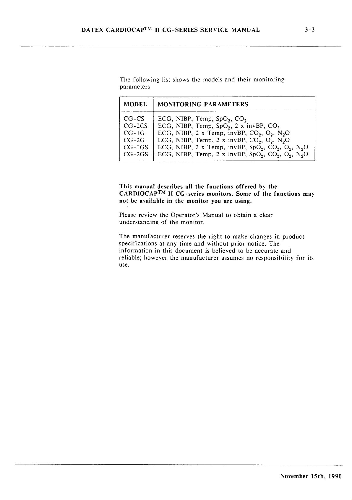
INTRODUCTION
Introduction
AND
and
applicability
This
service
Data
Display
DATEX,
maintain
monitors.
revision
summarized
revisions
(hardware)
software
Thé
revision
made
to
incompatible
type
designation
23-00
Functional
stickers
documentation.
represents
referred
is a revision
manual
order
and
This
of
the
in
given
changes
changes.
the
monitor
units
indicating
the
to
when
APPLICABILITY
of
this
(Doc.
No.
879040)
Model
repair
of a monitor
with
M-K9101NB
code
572760)
the
manual
monitors.
Section
in
Chapter
made
resulting
earlier
denote
-00
of
the
the
The
code
part
number
hardware
provide
DATEX
is
applicable
Differences
3.2
and
the
11.
Section
to
the
is
changed
in
units.
the
revision
unit).
monitor
modification
is
shown
and
changes
OF
THIS
manual
and
service
CARDIOCAPTM
technical
monitor
new
The
(PC
as
"y"
the
manual
information
for the
between
3.3
lists
and
when
spare
last
two
of
the
boards)
level
of
xxxxxx-y,
revision
are
indicated
MANUAL
the
Panasonic
(available
required
II
current
details
Section
technical
parts
digits
monitor
will
the
production
monitor
of
the
technical
that
of
have
production
where
level,
in
CRT
from
to
CG-series
revisions
earlier
3.4
the
changes
are
the
monitor
(e.g.
CG-1GS-
ID
code
the
"xx..."
which
this
manual.
are
are
is
November
15th,
1990
Page 18
DATEX
CARDIOCAPTM
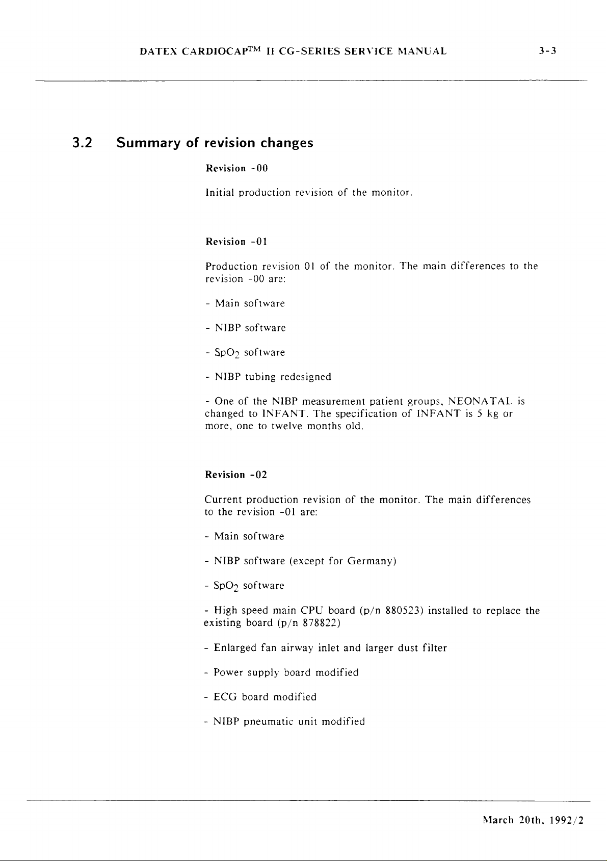
The
II
following
CG-SERIES
list
shows
the
SERVICE
models
MANUAL
and
their
3-2
monitoring
parameters.
MODEL
CG-CS
CG-2CS
CG-1G
CG-2G
CG-IGS
CG-2GS
This
manual
CARDIOCAP™
not
be
available
MONITORING
ECG,
|
ECG,
ECG,
ECG,
|
ECG,
¡
ECG,
describes
NIBP,
NIBP,
NIBP,
NIBP,
NIBP, 2 x
NIBP,
II
CG-series
in
the
Temp,
Temp,
2 x
Temp, 2 x
Temp,
all
the
monitor
PARAMETERS
SpO,,
SpO,,
Temp,
Temp,
functions
2 x
invBP,
invBP,
invBP,
invBP,
monitors.
you
are
CO,
2 x
invBP,
CO,,
CO,,
SpO,,
SpO,,
offered
Some
using.
of
by
CO,
O2,
O,,
CO»,
CO»,
the
the
N30
N30
Oz,
N¿0
03,
N30
functions
may
Please
review
understanding
The
manufacturer
specifications
information
reliable;
in
however
use.
the
Operator’s
of
the
reserves
at
any
this
the
monitor.
the
time
and
document
manufacturer
Manual
right
without
is
believed
to
obtain a clear
to
make
prior
to
be
assumes
changes
notice.
no
The
accurate
responsibility
in
product
and
for
its
November
15th,
1990
Page 19
DATEX
CARDIOCAPTM
II
CG-SERIES
SERVICE
MANUAL
3-3
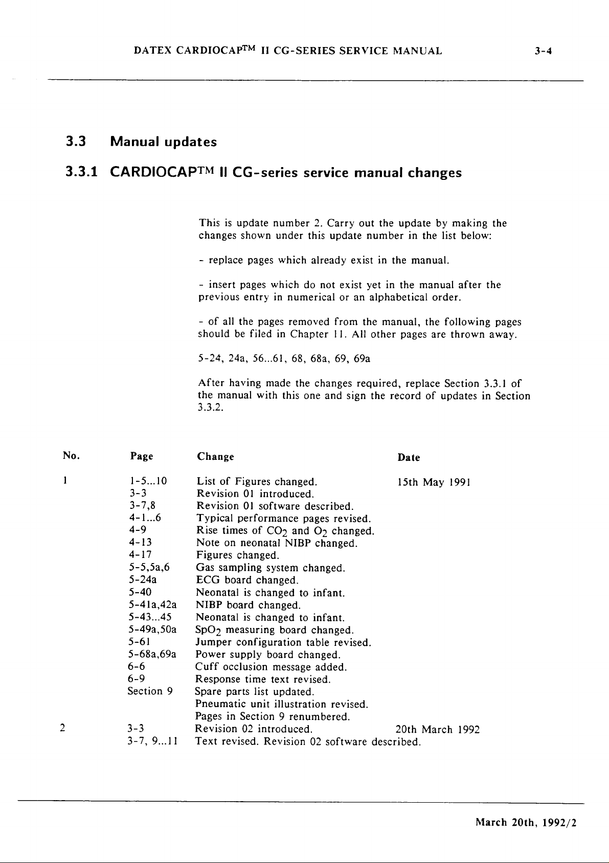
3.2
Summary
of
revision
Revision
Initial
Revision
Production
revision
-
-
-
changed
more,
Main
NIBP
SpO>
NIBP
One
changes
-00
production
-01
revision
-00
are:
software
software
software
tubing
of
the
NIBP
to
INFANT.
one
to
twelve
revision
01
of
redesigned
measurement
The
months
of
the
monitor.
the
monitor. The
patient
specification
old.
main
groups,
of
INFANT
differences
NEONATAL
is 5 kg
or
to
the
is
Revision
Current
to
the
-
Main
NIBP
-
SpO;
High
existing
Enlarged
Power
-
ECG
NIBP
-02
production
revision
software
software
software
speed
board
fan
supply
board
pneumatic
revision
-01
are:
(except
main
CPU
(p/n
878822)
airway
board
modified
unit
of
for
Germany)
board
inlet
and
modified
modified
the
monitor.
(p/n
larger
880523)
dust
The
main
installed
filter
differences
to
replace
the
March
20th.
1992/2
Page 20
DATEX
CARDIOCAPTM
II
CG-SERIES
SERVICE
MANUAL
3-4
3.3
3.3.1
Manual
updates
CARDIOCAPTM
||
This
is
changes
-
replace
-
Insert
previous
-
of
all
should
5-24,
24a,
After
the
3.3.2.
having
manual
CG-series
update
shown
pages
the
be
pages
which
entry
pages
filed
56...61,
made
with
number
under
which
in
numerical
removed
in
Chapter
this
service
2.
this
already
do
not
68,
68a,
the
changes
one
and
Carry
update
exist
or
from
11.
69,
sign
manual
out
the
number
exist
in
yet
in
an
alphabetical
the
manual,
All
other
69a
required,
the
changes
update
in
the
manual.
the
pages
replace
record
by
the
list
manual
order.
the
are
of
updates
making
below:
after
following
thrown
Section
in
the
the
pages
away.
3.3.1 of
Section
No.
]
2
Page
1-5...10
3-3
3-7,8
4-1...6
4-9
4-13
4-17
5-5,5а,6
5-24a
5-40
5-41а,42а
5-43...45
5-49a,50a
5-61
5-68a,69a
6-6
6-9
Section
3-3
3-7,
9
9...11
Change
Figures
of
List
Revision
Revision
Typical
times
Rise
on
Note
Figures
sampling
Gas
board
ECG
Neonatal
NIBP
board
Neonatal
measuring
SpO>
Jumper
Power
Cuff
Response
Spare
configuration
supply
occlusion
parts
Pneumatic
Pages
in
Revision
revised.
Text
changed.
introduced.
01
software
01
performance
CO»
of
neonatal
changed.
system
changed.
changed
is
changed.
changed
is
board
board
message
text
time
updated.
list
illustration
unit
Section
02
9
introduced.
Revision
described.
pages
O»
and
changed.
NIBP
changed.
infant.
to
infant.
to
changed.
table
changed.
added.
revised.
renumbered.
software
02
revised.
changed.
revised.
revised.
Date
15th
20th
described.
May
March
1991
1992
March
20th,
1992/2
Page 21
DATEX
CARDIOCAPTM
II
CG-SERIES
SERVICE
MANUAL
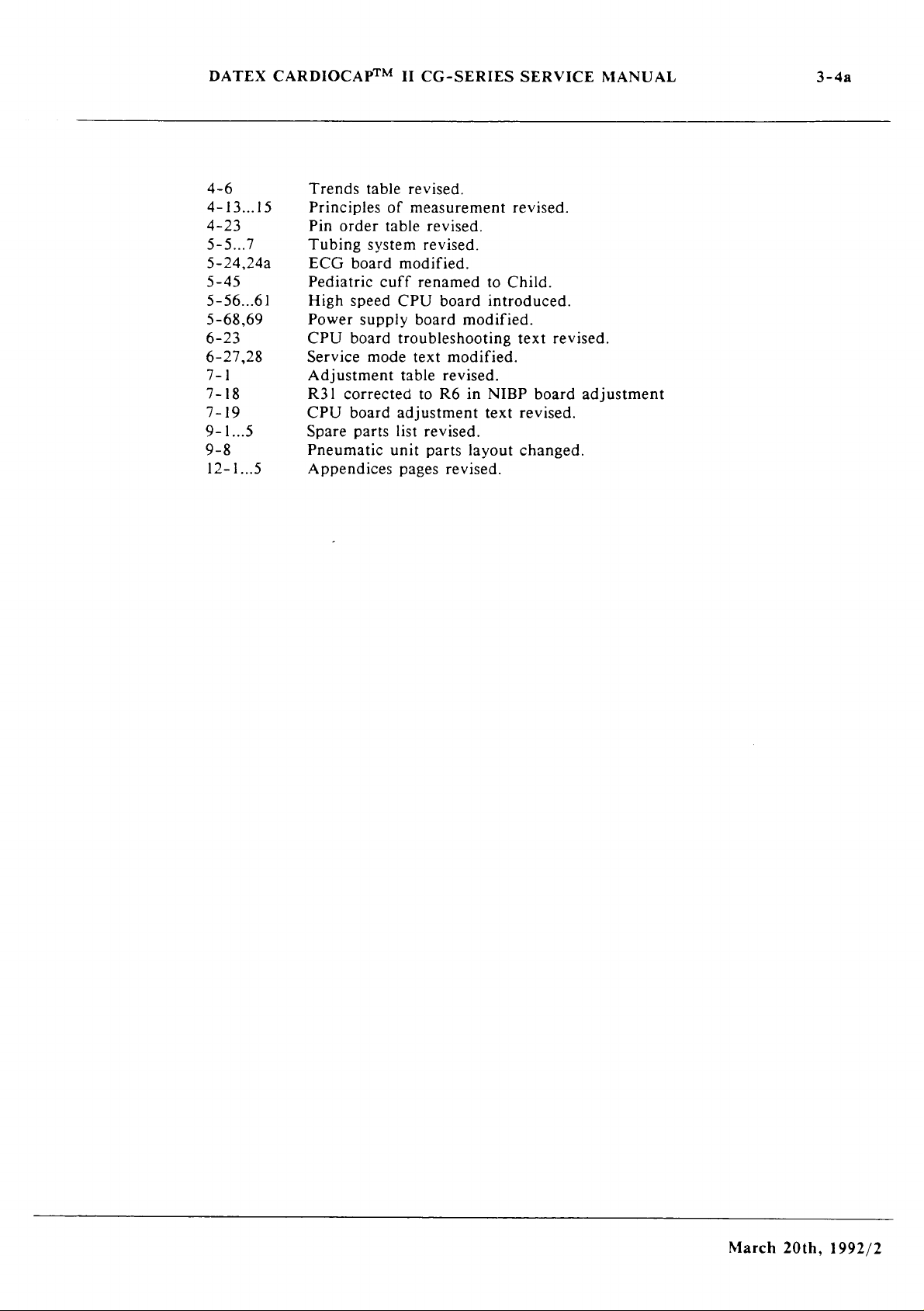
3-48
A
A
AB
UVU
UVU
AVU
LO
UI
ODO
—
|
to
3...15
3
7
4,24a
5
6...61
8,69
3
7,28
8
9
„5
1...5
Trends
table
Principles
Pin
order
Tubing
ECG
system
board
Pediatric
High
speed
Power
CPU
Service
supply
board
mode
Adjustment
R31
corrected
CPU
board
Spare
parts
Pneumatic
Appendices
revised.
of
measurement
table
revised.
revised.
modified.
cuff
renamed
CPU
board
board
modified.
troubleshooting
text
modified.
table
revised.
to
R6
in
adjustment
list
revised.
unit
parts
layout
pages
revised.
revised.
to
Child.
introduced.
text
NIBP
board
text
revised.
changed.
revised.
adjustment
March
20th,
1992/2
Page 22
DATEX
CARDIOCAPTM
II
CG-SERIES
SERVICE
MANUAL
3-5
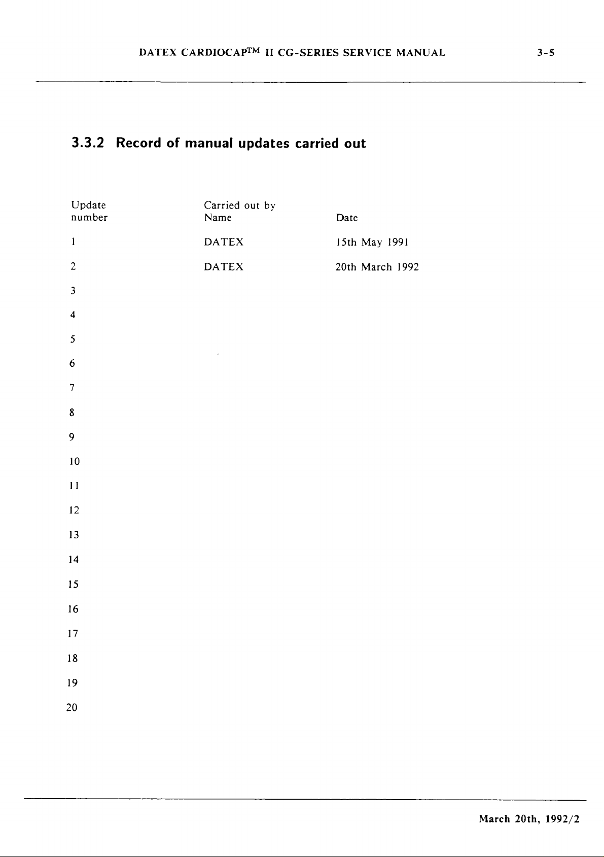
3.3.2
Update
number
1
2
Record
of
manual
Carried
Name
DATEX
DATEX
updates
out
by
carried
Date
15th
20th
out
May
March
1991
1992
10
11
12
13
14
15
16
17
18
19
20
March
20th,
1992/2
Page 23
DATEX
CARDIOCAP™
II
CG-SERIES
SERVICE
MANUAL
3-6
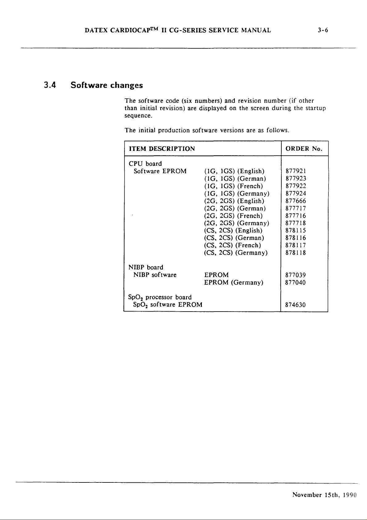
3.4
Software
changes
The
than
sequence.
The
ITEM
CPU
Software
software
initial
initial
production
DESCRIPTION
board
code
(six
revision)
EPROM
numbers)
are
displayed
software
(1G,
(1G,
(1G,
(1G,
(2G,
(2G,
(2G,
(2G,
(CS,
(CS,
(CS,
(CS,
and
on
versions
1GS)
(English)
1GS)
(German)
1GS)
(French)
1GS)
(Germany)
2GS)
(English)
2GS)
(German)
2GS)
(French)
2GS)
(Germany)
2CS)
(English)
2CS)
(German)
2CS)
(French)
2CS)
(Germany)
revision
the
screen
are
as
number
during
follows.
(if
other
the
ORDER
877921
877923
877922
877924
877666
877717
877716
877718
878115
878116
878117
878118
startup
No.
NIBP
board
NIBP
software
SpO,
processor
SpO,
software
board
EPROM
EPROM
EPROM
(Germany)
877039
877040
874630
November
15th,
1990
Page 24
DATEX
CARDIOCAP™
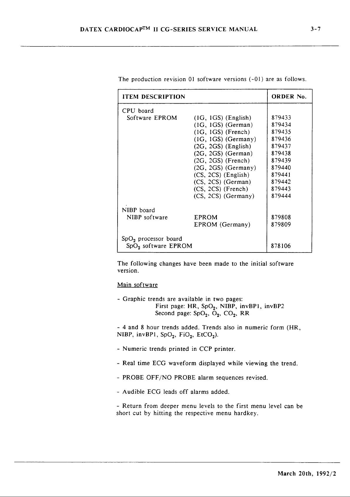
The
ITEM
CPU
Software
II
production
DESCRIPTION
board
EPROM
CG-SERIES
revision
SERVICE
01
software
(1G,
(1G,
(1G,
(1G,
(2G,
(2G,
(2G,
(2G,
(CS,
(CS,
(CS,
(CS,
1GS)
1GS)
1GS)
1GS)
2GS)
2GS)
2GS)
2GS)
2CS)
2CS)
2CS)
2CS)
MANUAL
versions
(English)
(German)
(French)
(Germany)
(English)
(German)
(French)
(Germany)
(English)
(German)
(French)
(Germany)
(-01)
are
ORDER
879433
879434
879435
879436
879437
879438
879439
879440
879441
879442
879443
879444
as
follows.
3-7
No.
NIBP
board
NIBP
software
SpO,
processor
SpO,
The
version.
Main
-
Graphic
software
following
software
trends
Second
- 4 and 8 hour
NIBP,
-
invBPI,
Numeric
Real
time
PROBE
trends
ECG
OFF/NO
board
EPROM
changes
are
First
trends
SpO,,
printed
waveform
have
available
page:
page:
added.
FiO,,
PROBE
EPROM
EPROM
been
HR,
SpO,,
EtCO,).
in
CCP
displayed
alarm
made
in
two
SpO,,
Os,
Trends
printer.
seguences
(Germany)
to
the
pages:
NIBP,
CO,,
also
while
invBPI,
RR
in
initial
numeric
viewing
revised.
879808
879809
878106
software
invBP2
form (HR,
the
trend.
t
Audible
-
Return
short
cut
ECG
from
by
leads
deeper
hitting
off
menu
the
respective
alarms
levels
added.
to
menu
the
hardkey.
first
menu
level
March
can
be
20th,
1992/2
Page 25
DATEX
CARDIOCAPTM
-
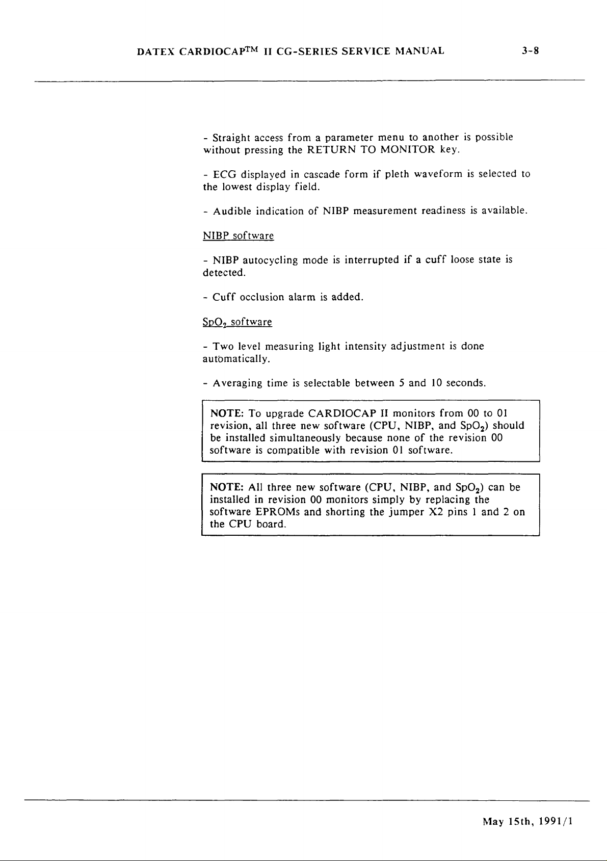
Straight
without
-
ECG
the
lowest
-
Audible
NIBP
-
NIBP
detected.
~
Cuff
SPO,
-
Two
II
access
pressing
displayed
display
indication
software
autocycling
occlusion
software
level
measuring
CG-SERIES
from a parameter
the
RETURN
in
cascade
field.
of
NIBP
mode
is
alarm
is
added.
light
SERVICE
menu
TO
MONITOR
form
if
pleth
measurement
interrupted
intensity
adjustment
MANUAL
to
another
waveform
readiness
if a cuff
key.
loose
is
is
possible
is
selected
is
available.
state
done
3-8
to
is
automatically.
-
Averaging
NOTE:
revision,
be
installed
software
NOTE:
installed
software
the
CPU
time
is
To
upgrade
all
three
simultaneously
is
compatible
All
three
in
revision
EPROMs
board.
selectable
CARDIOCAP
new
software
with
new
software
00
monitors
and
shorting
between 5 and
II
monitors
(CPU,
because
revision
(CPU,
simply
the
none
01
NIBP,
jumper
10
NIBP,
of
the
software.
and
by
replacing
X2
seconds.
from
00
to
01
and
SpO,)
revision
SpO,)
pins ] and 2 on
should
00
can
the
be
May
15th,
1991/1
Page 26
DATEX
CARDIOCAP™
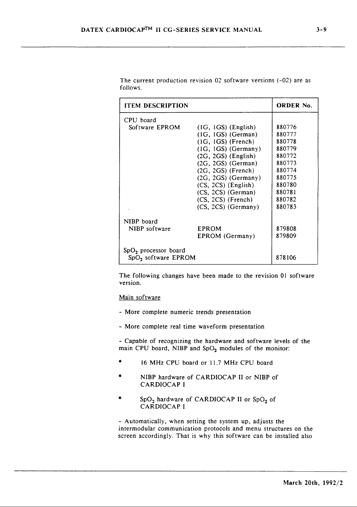
The
current
follows.
ITEM
CPU
Software
II
CG-SERIES
production
DESCRIPTION
board
EPROM
SERVICE
revision
(1G,
(1G,
(1G,
(1G,
(2G,
(2G,
(2G,
(2G,
(CS,
(CS,
(CS,
(CS,
02
1GS)
1GS)
1GS)
1GS)
2GS)
2GS)
2GS)
2GS)
2CS)
2CS)
2CS)
2CS)
MANUAL
software
(English)
(German)
(French)
(Germany)
(English)
(German)
(French)
(Germany)
(English)
(German)
(French)
(Germany)
versions
(-02)
ORDER
880776
880777
880778
880779
880772
880773
880774
880775
880780
880781
880782
880783
are
3-9
as
No.
NIBP
board
NIBP
software
SpO,
processor
SpO,
The
version.
Main
-
More
-
More
-
Capable
main
*
*
software
following
software
complete
complete
of
CPU
board,
16
MHz
NIBP
CARDIOCAP
board
EPROM
changes
recognizing
CPU
hardware
have
numeric
real
time
NIBP
board
I
of
EPROM
EPROM
been
trends
waveform
the
hardware
and
SpO,
or
CARDIOCAP
(Germany)
made
presentation
presentation
modules
11.7
MHz
to
and
CPU
II
the
revision
software
of
the
board
or
NIBP
879808
879809
878106
01
software
levels
monitor:
of
of
the
*
-
intermodular
screen
SpO,
hardware
CARDIOCAP
Automatically,
communication
accordingly.
when
That
of
CARDIOCAP
I
setting
is
the
protocols
why
this
system
and
software
II
up,
or
SpO,
adjusts
menu
structures
can
be
of
the
installed
March
on
the
also
20th,
1992/2
Page 27

DATEX
CARDIOCAPTM
into
CARDIOCAP
CARDIOCAP
-
The
patient
NOTE:
H
revision
new
features
activated.
NOTE:
II
revision
(pins 1 and 2 shorted
NIBP
software
This
This
II
CG-SERIES
I
units
group
new
01
units
need
new
00
units
II
revisions
(with
PEDIATRIC
software
without
the
new
software
with
in
jumpers
SERVICE
the
can
any
high
can
main
MANUAL
00
and
01
main
CPU
is
renamed
be
installed
modifications.
speed
be
installed
CPU
board
X2
and
units
board
main
X4).
as
to
CHILD.
into
Note
CPU
into
jumper
well
as
into
p/n
878822).
all
CARDIOCAP
that
board
all
CARDIOCAP
modifications
some
to
3-10
be
-
Improved
shivering
strong
NOTE:
H
SPO,
-
Improved
NOTE:
II
NOTE:
II
after
in
patients,
and
weak
This
revision
software
This
revision
This
revision
the
CPU
jumpers
Upgrading
To
upgrade
three
new
software
simultaneously
performance
high
pulses.
new
software
00
and
01
performance
new
software
01
units
without
new
software
00
units
together
board
X2
and
X4).
CARDIOCAP
(CPU,
as
well
in
blood
units
in
jumper
II
NIBP,
as
the
cases
like
pressures,
can
be
installed
without
NO
can
any
can
with
modifications
units
high
any
PROBE
be
installed
modifications.
be
installed
rev
from
and
speed
small
children,
low
blood
into
modifications.
conditions.
into
into
01 or
02
(pins | and 2 shorted
00/01
SpO,)
CPU
to
should
board.
pressures,
all
CARDIOCAP
all
CARDIOCAP
all
CARDIOCAP
main
02
revision,
be
moving
software
installed
and
all
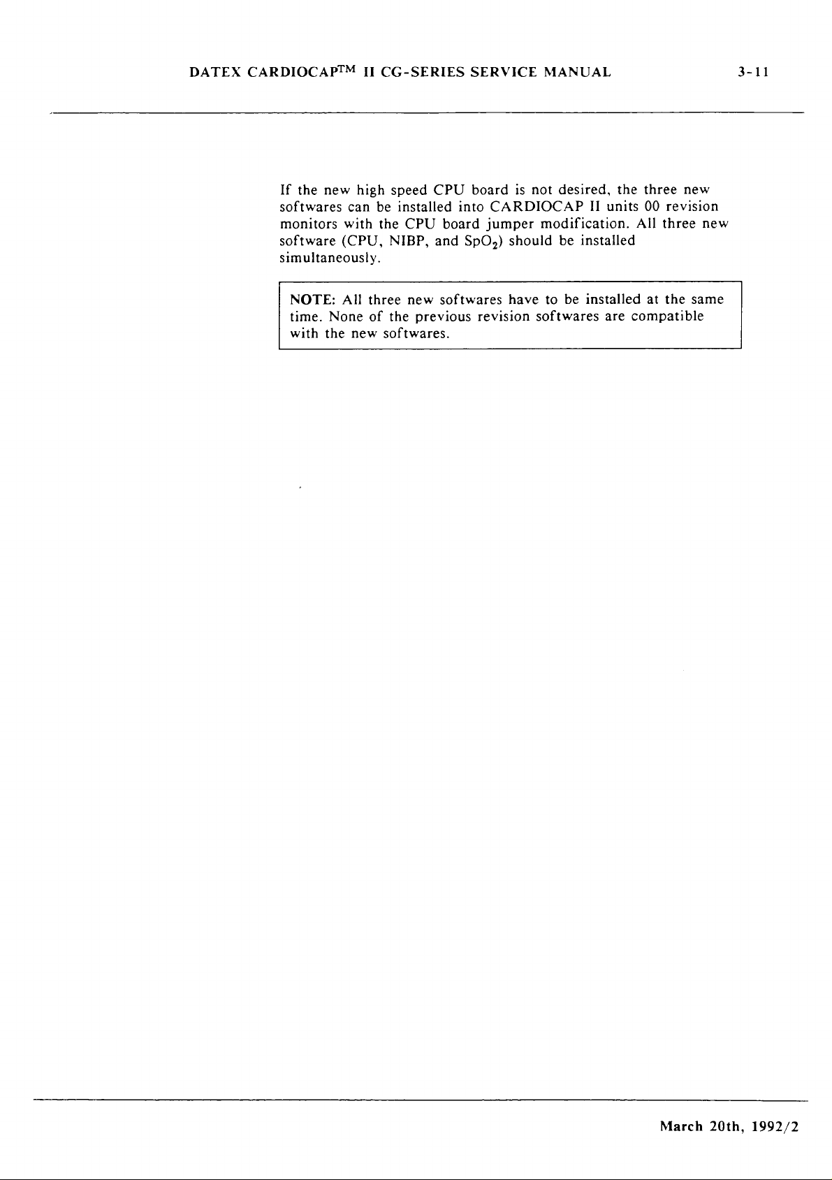
If
the
new
high
speed
softwares
revision
should
can
simply
monitors.
be
installed
CPU
board
be
installed
All
three
new
simultaneously.
is
not
desired,
into
CARDIOCAP
softwares
(CPU,
the
II
NIBP,
three
units
and
March
new
01
SpO,)
20th,
1992/2
Page 28
DATEX
CARDIOCAP™
If
the
softwares
monitors
software
simultaneously.
NOTE:
time.
with
new
None
the
II
high
can
with
(CPU,
All
new
CG-SERIES
speed
be
installed
the
CPU
NIBP,
three
new
of
the
softwares.
CPU
into
board
and
softwares
previous
SERVICE
board
CARDIOCAP
jumper
SpO,)
revision
MANUAL
is
not
desired,
modification.
should
have
be
to
softwares
II
installed
be
installed
the
units
All
are
compatible
three
00
revision
three
at
the
3-11
new
new
same
March
20th,
1992/2
Page 29
DATEX
CARDIOCAP™
II
CG-SERIES
SERVICE
MANUAL
4-1
da
回
©
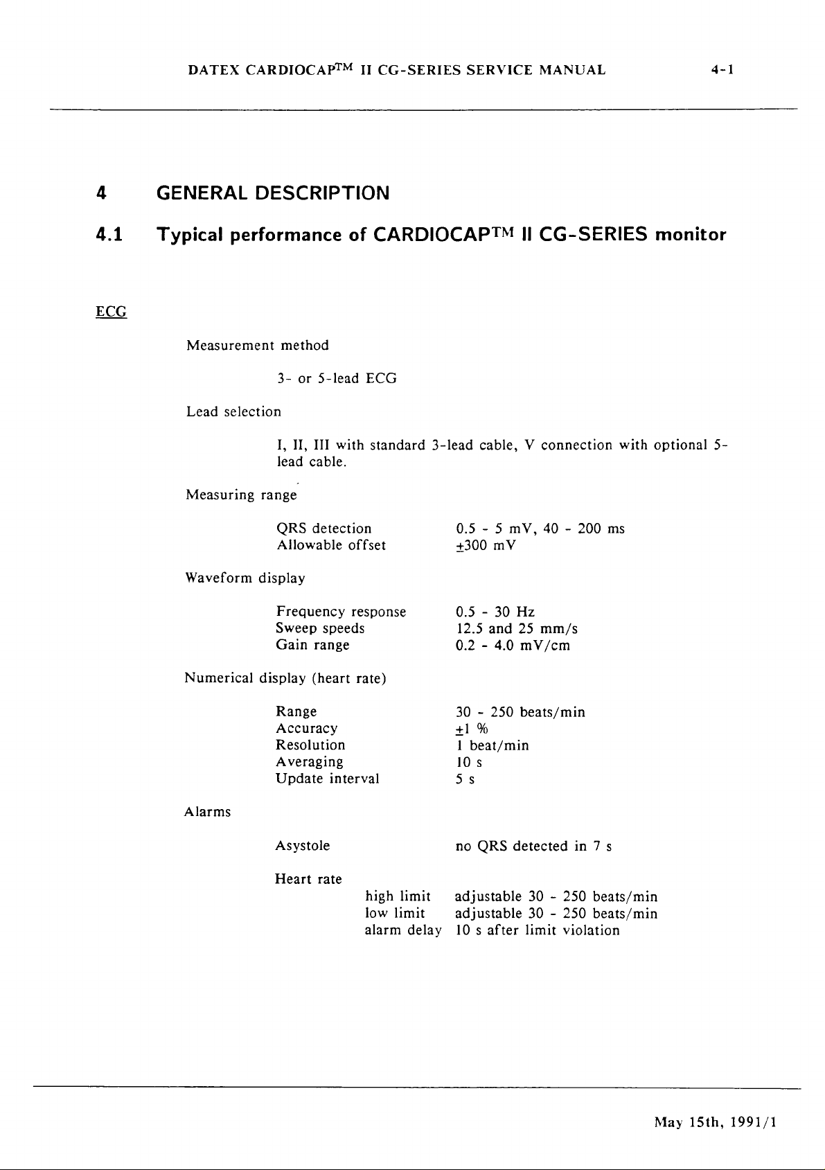
GENERAL
Typical
Measurement
Lead
Measuring
Waveform
DESCRIPTION
performance
method
3-
or
selection
I,
II,
III
lead
cable.
range
QRS
detection
Allowable
display
of
5-lead
with
offset
CARDIOCAP™
ECG
standard
3-lead
II
CG-SERIES
cable, V connection
0.5 - 5
+300
mV
mV,
40 - 200
ms
with
monitor
optional
5-
Numerical
Alarms
Frequency
Sweep
Gain
display
Range
Accuracy
Resolution
Averaging
Update
Asystole
Heart
speeds
range
(heart
interval
rate
response
rate)
high
low
limit
alarm
limit
delay
0.5 - 30
12.5
0.2 - 4.0
30 - 250
+1
1
beat/min
%
Hz
and
25
mV/cm
beats/min
10s
Ss
no
QRS
detected
adjustable
adjustable
10 s after
mm/s
30 - 250
30 - 250
limit
violation
in 7 s
beats/min
beats/min
May
15th,
1991/1
Page 30
DATEX
CARDIOCAPTM
II
CG-SERIES
SERVICE
MANUAL
4-2
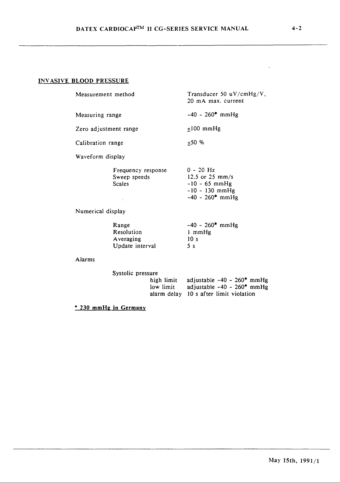
INVASIVE
BLOOD
Measurement
PRESSURE
Measuring
Zero
adjustment
Calibration
Waveform
Numerical
method
range
range
range
display
Frequency
Sweep
Scales
display
Range
Resolution
Averaging
Update
response
speeds
interval
Transducer
20
mA
max.
-40 - 260*
+100
mmHg
+50
%
0 - 20
12.5
-10 - 65
or
Hz
25
mmHg
-10 - 130
-40 - 260*
-40 - 260*
1
mmHg
10
s
55
50
current
mmHg
mm/s
mmHg
mmHg
mmHg
uV/cmHg/V,
Alarms
+
230
mmHg
Systolic
in
Germany
pressure
high
low
alarm
limit
limit
delay
adjustable
adjustable
10 s after
-40 - 260*
-40 - 260*
limit
violation
mmHg
mmHg
May
15th,
1991/1
Page 31

DATEX
CARDIOCAP™
II
CG-SERIES
SERVICE
MANUAL
4-3
TEMPERATURE
The
temperature
channel
is
YSI
400
series
probes
compatible
Numerical
Amplifier
Sensor
(YSI
NON-INVASIVE
Measurement
Measuring
Accuracy
display
accuracy
accuracy
400
series)
BLOOD
range
in
°C
Update
interval
PRESSURE
method
Compared
systolic
STD < 8
to
+5
mmHg
or
°F
auscultatory
mmHg,
+0.2°F
Oscillometric
Adult
method
STD < 8
24
s
+0.1°С
+0.2°F
+0.2°C
+0.4°F
+0.1°C
Pediatric
Infant
(25.0 - 45.0°С)
(77.0 - 113.0°F)
(15.0 - 24.9°C)
(59.0 - 76.8°F)
(15 - 45°C)/
(59.0 - 113.0°F)
in
mmHg,
25
to
25
to
15
to
adults
(slow
diastolic
260*
195
145
+4
/
/
mmHg
mmHg
mmHg
deflation
mmHg,
speed):
Compared
speed):
systolic
STD < 8
Accepted
Measurement
Measurement
heart
intervals
time
rate
to
auscultatory
+5
mmHg,
mmHg
method
STD < 8
mmHg,
30
to
manual,
1,
2,
3,
typical
slow
mode
normal
fast
mode
in
neonates
diastolic
255
beats/min
continuous
5,
10,
mode
15,
adult
35$
25
s
20
s
(normal
+4
mmHg,
for 5 min,
30,
60
min
deflation
infant
30
s
20
s
15
s
May
15th,
1991/1
Page 32

DATEX
CARDIOCAP™
II
CG-SERIES
SERVICE
MANUAL
4-4
Safety
Alarms
*
230
Limits
mmHg
Max.
measurement
Max.
inflation
Overpressure
measurement
Initial
Successive
Next
‘low
Stasis
Stasis
Mechanical
Independent
Systolic
high
low
in
inflation
infl.
infl
time
pressure
pressure
limit
limit
Germany
press’
pressure
limit,
pressure
infl.
pressures
pressure
message
safety
timing
time
stops
after
valve
circuit
Adult
2
min
280
320
185
syst + 40
+50
2
min
80
mmHg
limits
limits
OFF,
OFF,
mmHg
mmHg
mmHg
mmHg
+50
2
max.
cuff
pressurization
adjustable
adjustable
Pediatric
2
min
200
mmHg
220
mmHg
185
mmHg
syst + 40
mmHg
min
60mmHg
pressure
15 - 260*
15 - 260*
Infant
1
min
150
165
120
syst + 40
+40
I
min
40
to
330
to
max. 5 min.
mmHg
mmHg
mmHg
mmHg
mmHg
mmHg
mmHg
mmHg.
OXYGEN
SATURATION
Measurement
Numerical
Alarms
Pulse
beep
method
display
Range
Accuracy
Resolution
Averaging
Update
SpO,
pitch
corresponds
interval
alarm
to
delay
SpO,
Red
and
40 - 100
100 - 80
1%
6s
25
adjustable
adjustable
10 s after
level
infrared
%
%,
+2 % SpO,
40 - 99
40 - 99
limit
violation
light
%,
%
absorption
(+1
STD)
OFF
May
15th,
1991/1
Page 33

DATEX
CARDIOCAP™
II
CG-SERIES
SERVICE
MANUAL
4-5
PLETH
AIRWAY
Heart
Alarms
GASES
Gas
rate
sampling
Automatic
scale
User-adjustable
Range
Accuracy
Resolution
Averaging
Update
Heart
interval
rate
high
low
alarm
flow
rate
setting
scale
during
limit
limit
delay
when
probe
operation.
30 - 250
+1
%,
1
bpm
10
s
55
adjustable
adjustable
10 s after
180
+1
ml/min
is
attached.
bpm
bpm
30 - 250
30 - 250
limit
beats/min
beats/min
violation
Automatic
CO,/O,
Warm-up
collision
CO,
O,
compensation
broadening
time
Measurement
Range
Rise
time
Accuracy
Numerical
Waveform
Alarms
Measurement
Range
Rise
time
Accuracy
Numerical
for
atmospheric
effects
method
)
display
display
method
+
)
display
pressure
5
min
specifications
Infrared
variation,
to
operation,
absorption
0 - 10 % (0 - 76
<270
ms
<0.2
vol
%,
1.5
mmHg
ETCO,
sweep
Apnea
ETCO,
ETCO,
CO,
fast
analyzer
0 - 100%
<430
<2
FiO,
breath
updated
speed
(no
HIGH
LOW
rebreathing
response
ms
vol
%
and
ETO,
6.25
breaths
(adjustable
(adjustable
paramagnetic
CO,/N,0
30
min
to
technique
mmHg)
breath-to-breath
mm/s
detected
(1
%, 2 %, 3 %)
updated
in
9.9 - 0.0)
0.0 - 9.9)
oxygen
breath-to-
and
full
20
s)
May
15th,
1991/1
Page 34

DATEX
CARDIOCAP™
II
CG-SERIES
SERVICE
MANUAL
4-6
N,O
Respiratory
*)
This
the
same
%,
and
within 2 weeks,
been
turned
rate
performance
as
during
the
amount
Waveform
Alarms
Measurement
Range
Rise time
Accuracy
Numerical
Range
Detection
corresponds
calibration,
of
air
respiratory
on
for
at
least
display
method
+
)
display
in
rate
30
to
gas
the
circuit
is
minutes.
sweep
FiO,
FiO,
Infrared
speed
HIGH
LOW
0 - 100
<500
ms
<2
vol
%
FiN,0
4 - 60
1 % (7.6
baseline
patient
updated
breaths/min
monitoring
concentrations
is
less
than
<30
breaths
per
6.25
(OFF,
(adjustable
absorption
%
breath-to-breath
mmHg)
level
when
are
N,O 0 -
10
%,
minute
mm/s
adjustable
18 - 100
technique
variation
circumstances
70
%,
calibration
and
the
99 - 18
%)
in
CO,
O, 0 -
is
checked
monitor
%)
are
100
has
TRENDS
Revision
Revision
00
2
and
FiO,,
Ol
and
0.5,
Respiration
Amplitude,
except
hours
graphic
Diastolic
and
up
2, 4, 8 hours
NIBP.
Trend
0.5
2h
4h
8
Time
h
h
Pressures,
EtO,.
Rate,
FiCO,,
trends
of
Sampled
of
graphic
Systolic
EtCO,,
Sampling
HR
(10
SpO,
(30
Pl
(40
P2
(40
Heart
SpO,,
every
and
FiO,,
Rate
s),
s)
s,
20 s if
s)
CO,
Rate,
Pleth
10 s except
and
numerical
Diastolic
and
RR
(20
Pleth
(30
no
and
Respiration
Amplitude,
Pressures,
EtO,.
s)
s)
P2)
O,
(20
s) | every
FiCO,,
NIBP.
trends
Sampled
Display
every
every
every
Rate,
Systolic
EtCO,,
of
Heart
SpO,,
Pleth
as
follows
Rate
10 s value
10 s value
20 s average
40 s average
Rate,
March
20th,
1992/2
Page 35

DATEX
CARDIOCAPIM
II
CG-SERIES
SERVICE
MANUAL
4-7
4.2
四
a
O
INVASIVE
Technical
monitor
Subject
Defibrillation
Input
System
Allowable
Gain
Display
Pacemaker
Patient
The
protection
BLOOD
to
impedance
noise
range
bandwidth
Safety
ECG
PRESSURE
specifications
change
without
protection
of
notice
offset
pulse
detection
channel
and
features
pacemaker
an
pulse
CARDIOCAPIM
5000
>2.5
<40
+300
0.2
to
0.4
to
5 - 500
0.5 - 2
Type
integral
detection
electrosurgery
and
V,
400
Mohms/10
LV
(p-p,
mV
DC
4.0
mV/cm
30
Hz
mV,
ms
CF
isolation
rejection.
Il
CG-SERIES
J
Hz
RTI)
(-3dB)
pulses
filter,
defibrillator
Amplifier
Patient
Transducer
input
Input
Zero
Zero
channel 2 only)
Nonlinearity
Gain
Bandwidth
Zero
Calibration
Zero
Calibration
Safety
and
sensitivity
resistance
drift
drift
(pressure
drift
adjustment
range
set
accuracy
resolution
range
50
uV/cmHg/V,
20
mA
maximum
1019
ohms
«ἱ
mmHg/10°C
<2
mmHg/10°C
<1
%,
0-200
mmHg
<0.5 % f.s./10°C
0
to
20
Hz
(-3dB)
+100
mmHg
+50
%
+1
mmHg
+1
mmHg
Type
CF
isolation
5
Vdc
current
November
15th,
1990
Page 36

DATEX
CARDIOCAPTM
II
CG-SERIES
SERVICE
MANUAL
4-8
TEMPERATURE
The
temperature
channel
is
YSI
400
series
probes
compatible
NON-INVASIVE
OXYGEN
SATURATION
Amplifier
Sensor
(YSI
Patient
accuracy
400
Safety
BLOOD
Pressure
Patient
The
correlated
IL/282
Safety
pulse
CO-oximeter.
accuracy
series)
PRESSURE
transducer
oximeter
to
simultaneous
accuracy
accuracy
measurements
SpO,
measured
+0.1°C
+0.2°F
+0.2°C
+0.4°F
+0.1°C
+0.2°F
Type
better
or
Type
(25.0 - 45.0°C)
(77.0 - 113.0°F)
(15.0 - 24.9°C)
(59.0 - 76.8°F)
(15 - 45°C)
(59.0 - 113.0°F)
CF
isolation
than
+2 % (whichever
BF
isolation
are
statistically
on
an
Instrumentation
+3
mmHg
/
/
/
greater)
derived
Laboratory
and
Accuracy
Patient
PLETH
Automatic
User-adjustable
Amplifier
Patient
Safety
scale
Safety
setting
scale
during
when
operation.
Bandwidth
probe
100 - 80
80 - 50
50 - 40
Type
is
attached.
0.8
Type
%,
%, +3 % SpO,
%,
BF
isolation
to
15
Hz
BF
isolation
+2 % SpO,
unspecified
(-3
dB)
(+1
(+1
STD)
STD)
November
15th,
1990
Page 37

DATEX
©
A
Io
CARDIOCAP™
II
CG-SERIES
SERVICE
MANUAL
4-9
Iz
o
Measurement
Measurement
Gain
stability
Zero
point
Zero
temperature
Gain
temperature
Nonlinearity
N,0
compensation
Measurement
Measurement
21 % O,
21 % O,
Gain
Gain
Nonlinearity
drift
temperature
stability
temperature
range
rise
drift
error
range
rise
error
time
drift
drift
accuracy
time
drift
drift
0 - 10%
<270
<2 % f.s./4
<2 % f.s./24
<0.2 % fis.
<0.2 % f.s./°C
<2 % fis.
<2 % fis.
0 - 100
<430
<2
%/24
<0.2
<2
%/24
«0.3
«2
060
or O -
ms
days
/°C
%
ms
hours
%/°C
hours
%/*C
76
hours
mmHg
ALARMS
Measurement
Measurement
Zero
point
drift
Zero
point
temperature
Gain
temperature
Nonlinearity
range
rise
time
drift
drift
error
Adjustable
(approximately
Adjustable
SpO。,
Alarms
audio
high/low
ETCO。,
for
apnea,
OCCLUSION,
ECG
LEADS
alarm
900
FiO。
asystole,
AIR
OFF
Hz)
alarm
LEAK,
and
0 - 100
<500
<2
%/24
<0.4
<0.3
<2
%
sound,
limits
CO,
CUFF
REPLACE
%
ms
hours
%/°C
%/°С
rear
panel
for
heart
rebreathing,
OCCLUSION
WATER
loudspeaker
rate,
systolic
PROBE
TRAP
warnings
pressures,
OFF,
May
15th,
1991/1
Page 38

DATEX
CARDIOCAP™
II
CG-SERIES
SERVICE
MANUAL
4-10
DISPLAY
9"
green
Resolution
Clock
monochrome
1024 x 256
picture
pixels
tube
GENERAL
EXTERNAL
DATA
Standards
Operating
Storage
Power
Grounding
Interruptibility
DxWxH
Weight
fulfilled
temperature
requirements
CONNECTIONS
Serial
and
Composite
ECG,
output
ECG
AC,
Alarm
data
graphics
PLETHYSMOGRAPH
(SERIAL
test
signal
DC
power
signal
temperature
output
video
for
printer
output
&
ANALOG
supply
(Nurse
IEC
601-1,
CSA
22.2
10 - 35°C/50 - 95°F
-5 - 50°C/23 - 122°F
100/115/220/240
50/60
hospital
391 x 330 x 210
120
15
W,
min
Hz
600
15.3 x 13.0 x 8.3
14
kg / 31
computer
(AUX
interface
I/O
connector)
or
PRESSI,
I/O
connection
call)
safety
No
125-M1984
mA
grade
mm
inches
Ibs
(SERIAL
PRESS2,
connector)
class
V
I
&
CO,
ANALOG
and
O,
I/O
connector)
analog
waveform
November
15th,
1990
Page 39

DATEX
CARDIOCAP™
II
CG-SERIES
SERVICE
MANUAL
4-11
4.3
4.3.1
Principle
Principle
of
of
Absorption
10096
75%
operation
CO>/N20
The
CO,
infrared
chamber
two
wavelengths
wavelengths
and
the
micrometers.
from
of
these
sample.
Figure
y
light
in
other
the
signals
4.1
measurement
and
N,O
gas
as
it
passes
the
photometer.
using
is
that
of
is
that
The
signal
IR
detector
which
shows
the
Filter
Ν.Ο
Co;
Transmittance
measurements
through
The
an
infrared
the
CO,
of
the
N,O
processing
and
demodulate
correspond
CO,/N,O
T
|
Il
are
the gas
light
absorption
detector.
absorption
absorption
electronics
it
to
to
the
gas
absorption
based
sample
One
peak
peak
receive
get
DC
content
spectra.
1
|
on
absorption
in
measuring
is
measured
of
the
at
4.3
at
3.9
components
of
each
of
at
micrometers
the
signals
out
gas
in
the
50%
+
|
25%
4
30
Figure
4.1
,
CO,/N,0
Г
it
|
| |
|
ГИ
À
|
|
4.0
gas
|
\
|
\
M
absorption
5.0
pm
spectra
Wavelength
November
15th,
1990
Page 40

DATEX
CARDIOCAP™
II
CG-SERIES
SERVICE
MANUAL
4-12
4.3.2
4.3.3
Principle
Principle
of
O,
measurement
The
differential
principle
up
with a differential
measuring
off
at a frequency
proportional
gases
to
of
ECG
measurement
Electrocardiography
activity
with
ECG
of
electrodes
reflects:
Electrical
Normal/abnormal
Effects
Effects
of
of
oxygen
in a pneumatic
cell
with a strong
of
to
the
O,
be
measured.
the
heart
placed
activity
of
function
anesthesia
surgery
on
measuring
bridge
pressure
magnetic
165
Hz.
concentration
is
the
process
by
measuring
on
the
the
heart
of
on
heart
heart
function
unit
configuration.
transducer
field
The
output
difference
of
analyzing
the
electrical
surface
the
of
heart
function
uses
is
signal
the
the
paramagnetic
The
signal
generated
that
is
switched
is a DC
between
the
electrical
potential
body.
picked
in
a
voltage
the
produced
on
two
and
See
the
Operator’s
information.
Manual
for
electrodes
positions
and
other
November
15th,
1990
Page 41

DATEX
CARDIOCAP™
II
CG-SERIES
SERVICE
MANUAL
4-13
4.3.4
Principle
of
NIBP
NIBP
measuring
The
The
presumed
on
the
caused
monitor
The
invasive
with
functions
The
-
NIBP
Pneumatic
-
NIBP
Safety
NIBP
-
Twin
-
Blood
measurement
(Non-Invasive-Blood-Pressure)
NIBP
cuff
is
patient’s
by
calculates
NIBP
blood
the
main
NIBP
board
air
valve
tubing
hose
pressure
blood
measurement
systolic
the
measuring
are
system
pressure.
inflated
heart
pulsating
pressure
CPU
controlled
pump
cuff
uses
with a pressure
pressure,
values
unit
via
contains
rate,
collecting
artery.
for
is a fully
measuring
an
asynchronous
by
the
then
the
the
oscillometric
slightly
slowly
Based
systolic,
automatic,
system
NIBP’s
following
is
an
deflated
data
on
these
mean,
serial
CPU
main
indirect
measuring
higher
at a speed
from
the
oscillations,
and
diastolic
self-contained
which
communicates
channel.
in
the
parts:
method
than
oscillations
NIBP
for
principle.
the
based
the
pressures.
All
NIBP
board.
non-
The
NIBP
parts
The
pneumatic
valves,
of
the
and
board
system.
tubes
contains
contains
(see
the
two
Figure
pressure
damping
9.3).
transducer
chambers,
and
two
the
electronic
magnetic
March
20th,
1992/2
Page 42

DATEX
CARDIOCAPTM
II
CG-SERIES
SERVICE
MANUAL
4-14
4.3.5
Principle
of
SpO,
measurement
Spo,
Oxygen
A
major
hypoxia.
oxygenation
into
the
Most
of
hemoglobin.
oxygenated
hemoglobin
Dyshemoglobins:
(MetHb).
Pulse
Oxymetry
hemoglobin
wavelengths.
hemoglobin
principle,
fractional
SaO2frac = HbO っ /
is
the
most
concern
Thus
immediate
is
needed.
blood
the
it
dissolves
oxygen
The
total
oxyhemoglobin
(Hb)
and
carboxyhemoglobin
determines
(SpO>)
The
species
Pulse
Oxymetry
saturation
acutely
during
needed
on
limitation
can
necessary
anesthesia
and
direct
When
oxygen
into
by
hemoglobin
(HbO,),
other
forms
noninvasively
the
basis
is
that
be
discriminated
can
substrate
is
the
information
diffuses
the
plasma
the
body
in
the
reduced
of
hemoglobin
(HbCO)
of
light
correspondingly
be
calibrated
prevention
is
blood
the
absorption
by
SaO>frac,
(HbO2 + Hb + Dyshemoglobin)
for
survival.
about
from
the
and
binds
transported
is
composed
or
deoxygenated
such
and
methemoglobin
oxygen
at
only
the
measurement.
either
against
of
tissue
tissue
alveolus
to
hemoglobin.
bound
as
saturation
only
two
two
to
of
of
In
or
against
functional
SaO2func = HbO っ /
which
in
The
CARDIOCAP
saturation
accuracy
high
the
measure
Dyshemoglobin
The
wavelengths
and
monitor
wavelengths,
in
wavelengths
the
tissue,
is
less
sensitive
blood.
oxygen
saturation
SaOfunc.
of
SpO>
concentrations
calibration
oxygen
absorption
is
by
deoxygenated
measures
one
the
red
region
are
probe.
The
venous
II
monitor
measurement
method
content
levels,
of
mainly
the
in
(about
emitted
total
blood,
saturation
(HbO っ > + Hb),
to
changes
percentage
is
calibrated
The
advantage
of
carboxyhemoglobin
pulse
oxymetry
of
the
which
light
determined
deoxyhemoglobin
relative
the
absorption
arterial
of
near
660
by
normal
clinically
absorption
infrared
nm)
LEDs
blood, and
SaO2func,
of
Dyshemoglobin
measured
against
of
this
can
be
maintained
is
arterial
can
human
by
oxygenated
of
light
and
be
blood
may
(see
(about
detected
divided
by
the
method
in
blood.
not
able
at
be
blood
Figure
of
light
900
spectrum.
the
pulse
concentrations
the
DATEX
functional
is
that
the
even
at
rather
Independent
to
correctly
elevated
harmful
at
oxyhemoglobin
at
nm)
for
different
4.2).
The
two
and
These
patient.
the
by a PIN-diode
into
components
added
volume
of
other
in
of
of
March
20th,
1992/2
Page 43

DATEX
CARDIOCAPTM
II
CG-SERIES
SERVICE
MANUAL
4-15
arterial
synchronous
This
makes
noninvasively.
Plethysmographic
The
reflects
amplitude
Pulse
The
plethysmographic
noise
1.50T
blood.
fact
feasible
plethysmographic
the
rate
pulse
and
Only
with
is
most
the
biood
of
the
rate
calculation
checked
heart
essential
pulsation
waveform
pulse
the
last
beat
for
measurement
pulse
wave
waveform
is
wave.
to
separate
component
into
the
Puise
of
oxygen
is
derived
at
the
measuring
represents
done
by
The
signals
artifacts.
gives
transmitted
Oxymetry
saturation
from
the
perfusion.
peak
detection
are
variations
light
and
eventually
the
site.
Thus
of
filtered
intensity.
IR
signal
the
the
to
reduce
and
1.20
0.907
COEFFICIENT
ABSORPTION
(1079xcm2/EOUIV.)
0.60
0.30
0.00
p
“
F
0.60
A a
Figure
x
0.70
4.2
a
WAVELENGTH
Absorption
hemoglobin
À
0.80
(micron)
coefficients
in
the
red
0.90
of
oxy-
and
near-infrared
』
and
1.00
deoxy-
regions
March
20th,
1992/2
Page 44

DATEX
CARDIOCAP™
8
II
CG-SERIES
SERVICE
MANUAL
4-16
Intensity
transmitted
light
Transmitted
light
of
Imax
i
|
3
(DC-component)
No
pulsation
1
|
|
ーー
Imax
| .
Pulsatile
NPA
blood
Variable
due
to
volume
blood
Arterial
Venous
Tissue
AC-component
absorption
pulse
added
of
arterial
blood
blood
|
|
Figure
111
4.3
111
Absorption
11
of
infrared
|
light
in
the
finger
November
15th,
1990
Page 45

DATEX
CARDIOCAP™
Probe
The
standard
through
LEDs
Different
in
the
one
kinds
II
CG-SERIES
probe
finger
half
and
of
is a finger
(see
Figure
the
photodiode
probe
are
SERVICE
clamp
4.4)
also
available
MANUAL
probe
and
detector
which
contains
in
from
measures
the
light
the
DATEX.
other
4-17
source
half.
EMITTER
ーー
LA
PRED
デレ
Va
RED
Figure
T
|
|
|
|
!
|
|
|
|
4.4
PROBE
6
Cliplite™
CABLE
|
|
probe
PROBE
parts
CONNECTOR
layout
and
schematic
_
diagram
May
15th,
1991/1
Page 46

DATEX
CARDIOCAPTM
II
CG-SERIES
SERVICE
MANUAL
4-18
4.4
General
block
diagram
The
monitor
for the
-
-
-
-
-
-
~
-
-
ECG
Invasive
NIBP
Probe
CO,/N,O
Oxygen
Gas
Main
A/D
Video
video
parts
consists
included
measuring
BP
measuring
and
SpOQ,/pulse
measuring
measuring
measuring
processor
converter,
control
signal
of
the
in
the
electronics
and
temperature
electronics,
unit
electronics
board
and
board
following
monitor
oximeter
unit
including
real
time
to
convert
modular
you
are
measuring
pump,
measuring
analog
clock
the
CPU
parts
using):
electronics
and
tubing
signal
commands
(see
page
board
multiplexer,
3-2
into
-
-
-
-
-
See
Figure
For
monitor
Chapter
Video
Transformer
voltages
Mother
display
and I/O
board
buffers
Tactile
Loudspeaker
9.
4.5
parts
membrane
for
module
and
power
functions
including
keyboard
unit
the
monitor
locations
see
supply
signal
block
the
exploded
board
buses
and
diagram.
to
generate
view
analog
(Figure
necessary
input
signal
9.1)
in
November
15th,
1990
Page 47

91814
Sp
[E133
1901
WeIZEIP
AC
in
|
I
Ton5
former
|
Room
Air
Sample
Gos
IN
る
x
る
È
Я S
や
3
~~
Power
from
Video
Control
Boord | Main
pu
Man
Flow
Water
пор
>
Side
Flow
a
5
a
va
£
a
E
っ
5
A A A
Supply
_
mé
5
a
SE
E
O 6 Ox
S9 o UNE
7 Š à xa
©
ваз,
©
o
(1/0)
o
Zero
NV
Valve
<
$
一 5 B
Sa
o
っ
の
AA
Board
Processor
c02/N20
Measuring
N
|
CO2/N20
Measuring
Unit
Bleed
Valves
<
A
©
=
O
A
“NIBP
Processor
Board
Boord
(1/0.
MUX,
Pressure
Transducer
|
Board
trom
Power
Supply
Board
REF
IN
—
Room
Air
filter
AAA
TRY
Constriction
Cie
Cuff
Lead
Sel
Ρ2
Pressure
Transducer
ADC,
CPU,
Pressure
Volve
/
REF
=
=
=
sete
ROM,
ECG
RAM)
y
Oxygen
Meosuring
Unit
n
INOP
lo
Power
Supply
Board
Damping
Chamber
Pt
PI
€———
1
W
12
À
71
Video
Control
Board
Sampling
Pump
—>
——>
Serial & Analog
Rear Ponel
5р02
Connector
1/0
K
from
Power
Connector
==>
Baord
$
Sp02
Processor
Board
Supply
Small
Damping
Chamber
Cos
Flow
Electrical
1/0
5902
р
Messuring
Board
Video
Display
Module
Board
J
Poth
.
Ep
ーー
ーー
Key-
board
CRT
Video
Screen
Sample
Gas
テー
QUT
N
,
XILVO
pIidVODOITAVO
M
SIINAS-99
IDIAAAS
IVANVIA
19QUIIAON
"UIST
0661
ES
AC
、
АС т Γη
Trans--
8
former
from
Control
Room
Ar
|
ον
Water
Tro
ーー
5
$
2
a
3
S
-
Video
Boord
ασ
How
PZ
Side
Flow
SE
E
2
o a 2
£
в
Е
e
A
©
£
ーー
Power
|
|
——
AC
포복
5
5
ED
боя
1
や
E > Ris
£
2 e of
Supply
. "
Main
Zero
Valve
с
2
È
-
бо
с O =
5,7
ser
D
xd
AAA
(1/0)
Board
Processor
πα.
с
are
Unit
——
CC:
>
È
o
O
Boord
Boord
u
ng
—>
Room
|
Bleed
Valves
m
NIBP
Processor
Board
(1/0,
from
ro
MUX,
Pressure
Transducer
ーー
Power
Boord
ADC,
|
CPU,
f
Pressure
Transducer
一
Filter
Ar
上
AAA
ТУТ
Cometriction
Cucsette
ROM,
Pressure
Valve
P2
Leod
Sel
ECG
INOP
RAM)
to
Power
Supply
Boorg
M
m
Damping
Chamber
PI
IPT
Ἔ
|
T
~
一
Video
Control
Boord
from
Sampling
Pump
—>
>
Serial 4 Analog
Rear
Panel
t
SpO2
Connector
1/0
Board
4
SpO2
Processor
Boord
Power
Supply
Cos
Electrical
МО
Connector
Video
Display
Module
Board
=%
Smoli
Damping
Chamber
Flow
Poth
5p02..
MeosuringlE—=>
Board
Ш
Lie
-...> © LE
- .
+
Key-
а
RT
Video
Screen
Е
7
61-+
Page 48

DATEX
CARDIOCAP™
II
CG-SERIES
SERVICE
MANUAL
4-20
4.5
CO:
N20
Wiring
Loudspeaker
diagram
Rear
panel
Measuring
unit
7 =
κο
o
x
HA
mz
NIBP
RD
YE
valve
BU
NIBP
pump
Video
displav
unit
Pressure
Oz
Measuring
Sample
valve
pump
unit
Power
supply board
c
COz/N:O
Transformer
100
Video
control
CPU
-board
Measuring
NIBP-board
board
board
board
processor
SpOz
board
WO
;
{
と 3
im
connector
SpO2
[Il
Figure
4.6
Zero
valve
Wiring
diagram
IPT
-board
EK
G-board
Keyboard
unit
board
measuring
SpO2-
November
15th,
1990
Page 49

DATEX
CARDIOCAP™
II
CG-SERIES
SERVICE
MANUAL
4-21
4.6
4.6.1
4.6.2
External
connector
Input/Output
Connectors
configurations
specifications
Serial
Serial
Composite
ECG,
output
ECG
AC,
Alarm
Table
data
I/O
connector)
Output
PLETHYSMOGRAPH
(SERIAL
test
DC
signal
4.1
Front
Front view
output
video
signal
power
view
for
supply
(Nurse
Pin
for
computer
Graphics
output
&
ANALOG
connection
call)
order
interface
of
Printer
the
PIN
—
D
©
LU BR
ひひ
ココ
の
つら
PIN
—
WD
BR
OU
-J
oo
© D
or
I/O
ECG
PRESSI,
(AUX
connector)
connector
(SERIAL
I/O
PRESS2
SIGNAL
R
L
N
(I, II,
Е
(У-5)
C
(V-5)
Cable
not
connected
not
connected
not
connected
not
connected
SIGNAL
RA
LA
LL
(I,
LL
(V-5)
У
(У-5)
Cable
not
connected
not
connected
not
connected
not
connected
£
connector)
analog
(IEC
Ш)
ог М (У-5)
shield
(AAMI)
II,
Ш)
shield
ANALOG
waveform
standard)
or
RL(V-5)
November
15th,
1990
Page 50

DATEX
CARDIOCAP™
Table
Front
Table
Front
4.2
4.3
view
II
CG-SERIES
Pin
(PRESSURE
view
Pin
(PRESSURE
order
order
SERVICE
of
the
1)
PIN
m
D
&
BR
oo
0
of
the
2)
PIN
mm
WND
BR
OU
-
©
DO
©
invasive
invasive
MANUAL
pressure
SIGNAL
P+
P-
Excitation
Excitation
not
connected
LED
Ground
LED
Pleth
in
Pleth
Ground
-Invbpflg
pressure
SIGNAL
P+
P-
Excitation
Excitation
not
connected
not
connected
not
connected
not
connected
P
Ground
-Invbpflg
connector
voltage
voltage
connector
voltage
voltage
-
+
-
+
Table
Front
4.4
view
Pin
(SpO:)
order
of
the
PIN
一
WEN
JU
© D ©
pulse
oximeter
SIGNAL
Is
Ib
no
connection
Probe
Probe
Ground
Iled
Vb
Ground
+12
probe
(-4
Vp
connector
identification
identification
40.3
V)
November
15th,
1990
Page 51

DATEX
CARDIOCAP™
II
CG-SERIES
SERVICE
MANUAL
4-23
о
9ο
бо
o ©
o
o
o
o
об
o
o
о
бо
бо
бо
o
Table
PIN
一
WN
Ph
Un
D
-J
00
NO
©
—
M
ne
一
DW
IAM
一 一 一
w~
一
COO
ID
to
NY
WN
WMA
NNN
4.5
NO.
Pin
©
=
00000000000000007
order
of
the
SIGNAL
Protective
TXDO
RXD0
RTSO
CTSO
Gas
Signal
Test
+12
-12
+15
-15
SpO,,
O,,
5
VDC
SpO;,
Inv.
ECG
Inv.
CO,
+22
Infrared
-22
20
20
SERIAL
freeze
(TTL)
VDC
VDC
VDC
VDC
10 V =
10 V =
10 V =
BP2
(Gain = 1660)
BP
10 V =
VDC
VDC
VAC
VAC
&
ground
(TTL)
ground
(Do
50
mA
100
100
300
mA
-40 - 255
255
mmHg
500
signal, 0 -
500
500
mA
500
mA
ANALOG
(RS232C)
-"-
ーー
ーー
(Do
not
max
ーー
mA
max
ーー
100
%
%
max
100
%
mmHg,
approx
10
%
mA
max
mA
max
max
max
connector
not
connect)
connect)
10
V
0 - 10
10
V
V
March
20th,
1992/2
Page 52

DATEX
CARDIOCAP™
II
CG-SERIES
SERVICE
MANUAL
4-24
Table
5
ο δ
o
っ 9
o
o
o
っ
ος
со
o
o
っ
o
o
©
PIN
1
2
3
4
5
6
7
10
11
12
13
14
15
16
17
18
19
20
21
22
23
24
25
4.6
NO. | I/O
Pin
O
I
O
I
I
1
I
O
O
O
O
0
O
order
of
the
AUX
I/O
SIGNAL
Protective
TXD1
RXDI
RISI
CTSI
(PB1)
Signal
(PBO)
+12
VDC
-12
VDC
Not
connected
Not
connected
CTS2
TXD2
+5
VDC
RXD2
(PAS)
(PA6)
RTS2
(PA7)
+26
VDC 1 A
not
connected
+29
VDC 1 A
22
VAC
22
VAC
ground
ground
(TTL)
(TTL)
(TTL)
(TTL)
(Alarm)
1 A max
1 A max
connector
(RS
232)
-"-
-"-
-"-
(not
used)
(CPU
(NIPB
(not
used)
max
max
->
->
NIBP)
CPU)
NOTES:
Video
connector
-
CTS = clear
-
RTS = request
-
no
serial
-
serial
channel 2 is
communication
CONNECT
output
1
Vpp,
24
MHz,
For
internal
to
send
to
send
inputs
in
between
EXTERNALLY.
75
connector
(+12 V =
(not
use
unbuffered
main
ohm,
hsync
pin
configurations
in
CPU
For
enable
use)
TTL.
and
test
15.75
transmission)
It
is
used
NIBP
unit.
purpose
kHz,
vsync
see
only.
Tables
for
internal
DO
50
Hz
5.3 - 5.25.
NOT
November
15th,
1990
Page 53

DATEX
CARDIOCAP™
II
CG-SERIES
SERVICE
MANUAL
4-25
Table
._
|
Pin | C
1
|
GND A analog
2
|
+10Vref.
3 | DAC6
4
|
DAC4
(ECG
el.test)
5
|
DAC2
ext
Pleth
6
|
DACH
ext
CO, KB5
7
|
ADC6
(mux.
,bp2)
8
|
ADC4
(pulse & temp)
9
|
ADC2
(ECG)
10
11
12
13
14 | ag
15
16
17
18 | SER
19
20
21 | SER
22 | TIMER
23
24
25
26
27 | DØ
28 | ИЗ
29
30
31
32
8060
(606)
A6
A4 up
|A2 | bus
|
T1
(CTS9)*
WR
TA
(RTSG)*
IN
addr
(8031)
|p1.9*
INT
(video
IN 1 (RxD
IN
SER
IN 2 (RxD
|D6
D4
İn?
+5V
ES
| 19Vac
GND D (digital) | PAT->
|
data
2A
2A
0.14
cntrl)
(İP
bus
digital
(dirty)
2)
2)
B)
4.7
|
System
B
digital
(80
KB1
KB2
KB3
KB4
o
bus
(keyboard)
X2
X3
X4
Y2
X1|Motor-
Yİ
KB6
Y3
KB7
Y4
PBA<-DECT
PB1<-DECH
PB2<-
PB3<-EXT.DECT
PB4<-EXT.DEC9
PB5<-CTS2
PB6<-CTS1
PB7<-CTSÿ
PCg<-ECG
PC1<-(PB2
(CTSB)
(CTSA)
inop
Tnop)
PC2<-
PC3<-
PC4->Pressure
PC5->PUMP
PC6->Gas
PC7->RTSØ
PAB->IPT
PAT->IPT
PA2->IPT
PA3->IPT
PA4->
|
РАБ->
|
PA6->
|
zero
addr.
addr.
addr.
addr. 3 (gain)
mag.
OSC
mag.
0
1
2
anal.bus
sync
T+
T-
TIME
+6.5V/CD
N,0
N50
CO,
CO,
N20
C0,
LAMP
|6.5\/АА
valve
OUT
zero
zero
zero
zero
cal/WR
cal
ON
valve
|
|
A
+15V,
~15V,
DAC7
(selftest)
|
DAC5
(alarm)
|
DAC3
(ext)
|
DACT
(ext)
|
ADC7
(ext,selftest)
|
ADC5
(GASPRESS)
ADC3
(02)
ADC1
(N。
zero | A7
A5
A3
A1
TORO
RD
Reset
SER
OUT
Pitt
RTS A (OP
SER OUT 1 (TxD
RTSB
(OP
SER OUT 2 (TxD
|
D7
|
05
D3
‘DI
INT
1
+5V
data
|
+15V
2A
|
+I2V
1A
(GND D (dirty)
|
0,2A
analog
0,2A
analog
0,
0)
(0.1-5V)
(8031)
9)
1)
retention
(dirty)
(video)
A)
B)
J
|
|
|
|
|
|
|
|
|
*
not
used
PPI
Mode
fl
contr.
w#83H
November
15th,
1990
Page 54

DATEX
CARDIOCAP™
II
CG-SERIES
SERVICE
MANUAL
5-1
5
5.1
DETAILED
Gas
sampling
DESCRIPTION
system
The
function
the
monitor
and
condensed
Water
The
sample
is
divided
The
main
Section
hydrophobic
The
side
collection
filter
to
trap
into
flow
5.2).
flow
bottle
collect
gas
gas
This
filter.
OF
MODULES
of
the gas
sensors
water
enters
two
goes
flow
creates a slight
which
in
from
the
flows,
into
the
bottle.
sampling
at a fixed
the
monitor
main
the
is
separated
causes
system
rate
and
gas
stream.
through
flow
and
measuring
system
from
sub-atmospheric
fluid
removed
is
to
to
the
side
the
draw
sample
separate
water
flow
(see
(described
sample
pressure
by
the
hydrophobic
gas
impurities
trap,
where
Figure
in
in
flow
within
by
into
it
5.1).
a
the
Sampling
The
sampling
The
resistance
software
sequence.
The
small
to
propagate
replaced.
The
Nafion™
A
special
balance
will
partial
with
valve.
the
prevent
pressure
dry
line
to
set
inner
within
tube
sample
errors
gases.
line
is
an
integral
established
the
flows
diameter
the
tube,
tube
(tube
A,
see
gas
humidity
caused
when
humid
It
is
inserted
by
the
and
pressures
causes
Figure
by
the
gases
between
part
sampling
fluids
so
that
with
effect
of
when
5.2
that
are
the
the
total
line
during
such
as
the
and
Table
of
ambient
of
water
measured
water
sampling
is
used
the
turn
blood
line
is
5.1)
vapor
after
trap
system.
by
the
on
or
mucus
clogged,
is
used
air.
The
on
gas
calibration
and
the
zero
not
it
to
tube
is
November
15th,
1990
Page 55

DATEX
CARDIOCAP™
Zero
The
main
to
the
the
zero
minutes
activated,
valve
flow
CO,/N,O
points
and
room
II
CG-SERIES
passes
measuring
for the
thirty
air
SERVICE
through a magnetic
unit.
This
CO,/N,O
minutes
is
drawn
after
into
and
turn
the
MANUAL
valve
valve
O,
measuring
on.
When
internal
before
is
activated
the
system
proceeding
to
units
at
valve
is
and
the
5-2
establish
five
gas
sensors.
Gas
measuring
After
the
measuring
passed
through
(measurement)
measurement
light
intensities.
unit.
unit
zero
valve,
units.
In
chambers
and a chamber
is
made
See
the
gas
the
CO,/N,O
containing
by
determining
Section
passes
through
measuring
containing
5.2.2
for a detailed
the
the
the
unit,
main
flow
reference
ratio
between
CO,/N,O
and
infrared
gas
gas.
The
the
description
O,
light
two
of
this
is
The
oxygen
and
the
pressure
produced
field.
See
Pressure
The
pressure
between
pressure
trap
filter.
then
once
Normally
and
the
sensor
other
draws
differential
when
both
Section
valve
valve
the
O,
measurement
gradient
The
measurement
an
hour.
the
pressure
reference
detects a gradient
initiate a pressure
greater
"REPLACE
than
-5
mmHg,
WATER
has
two
inputs.
in
room
air
transducer
gases
are
5.2.5.
Both
gas
is
used
to
measure
flow
reflects
flow
between 0 and
measurement
the
is
gradient
is
approximately
the
software
TRAP"
to
condition
One
input
accepts
for
to
compare
exposed
flows
and
reference.
to
exit
the
the
of
The
the
pressure
an
oscillating
from a single
pressure
O,
reference
the
D-FENDTM
performed 2 minutes
between
-5
every
be
the
O,
+8
mmHg.
mmHg,
15
minutes.
causes
the
displayed.
measurement
the
pressure
message
the
sensor
magnetic
gradient
after
If
the
If
the
main
flow
uses
a
gradient
port.
flow.
This
water
start-up
flow
software
valve
will
gradient
is
November
15th,
1990
Page 56

DATEX
CARDIOCAP™
Flow
The
internal
are
used
the
flow
total
In
CS and
extra
II
CG-SERIES
cassettes
flow
to
set
the
rate
into
flow
rate
of
2CS
models,
cassettes.
rates
are
side
flow
the
measurement
the
sampling
The
SERVICE
set
using
rate
system.
O,
sensor
and
side
MANUAL
flow
cassettes.
the
O,
of
the
is
compensated
These
reference
O,
sensor and
flow
by
three
5-3
cassettes
rate,
the
Sampling
The
sampling
Hz/12
The
silence
V/0.4 A square
damping
the
pump
pump
chambers
exhaust
and
damping
is a vibrating
wave
are
flow.
chambers
current.
used
to
membrane
even
out
pump
the
pulsating
driven
by a 50
flow
and
November
15th,
1990
Page 57

DATEX
CARDIOCAPTM
II
CG-SERIES
SERVICE
MANUAL
5-4
11101
ados
SEY)
\
i
4
|
|
buunsoawy
91055814
BABA
di
132NPSUDIL
91155844
|
uabAxD
uu
|
buunsosn
OZN/
709
HUN
uugo3
ay
La
' )
ーー
15
fury:
_
3
i
JO
Ču
Lo
but)
Cy)
-
91055315}
7
4911
"4
лу
NI
7
333
оба
oras
aan)
315594
SOT
"SOL
CDL
9ο
90
ΘΛΙΟΛ
3
う
TIPSuO」」
|
9!
Co
bunnsosy
00760?
ーーーー
un
|"
BABA
0437
/
一
Qu
JON
эм
3194205
ο
alv
NI
509
лу
оон
SIZ
"89
93
Figure
5.1
Gas
sampling
system
schematic
diagram
November
15th,
1990
Page 58

DATEX
CARDIOCAP™
ji
CG-SERIES
SERVICE
MANUAL
5-5
Measuring
/
/
|
\
|
unit
M
Figure
Rear
CO2/N20
X
\
/
5.2
Gas
sampling
(modification
Sample
A
panel
、
Pressure
transducer
out
system
level 6 and
layout
higher)
in
CG-CS
O2
measuring
three
panel
圖
[e]
|
一
一
sí
|
|
Damping
chamber
|
|
iI
|
し
PA
u
=
+
A)
Small
chamber
А
O
damping
Measuring
unit
/
7
i
|
|
|
i
G)
A
ITS
3)
O
extra
\
\
ond
CG-2CS
unit
-s
cassettes
AS
=
|
compensated
shown
In
monitors,
by
below.
SE
\
\
3
March
20th,
\
1992/2
Dea,
don
τω
ha
ho
x
ba
©
С
NC
NCE
Front
D-fend
panel
water
(4
trap
È
Zero
k
出
valve
o
|
Pressure
|
valve:
-
Page 59

DATEX
CARDIOCAP™
II
CG-SERIES
SERVICE
MANUAL
5-6
Table
TUBE
A
B
]
2
3
4
5
6
7
8
9
10
11
12
13
14
15
16
17
18
19
20
21
22
23
24
25
NO. | DESCRIPTION
Special
Sample
1.7/1.05
1.7/1.05
1.7/1.05
1.7/1.05
1.7/1.05
1.7/1.05
1.7/1.05
1.7/1.05
1.7/1.05
1.7/1.05
1.7/1.05
1.7/1.05
3.18x6.35
3.18x6.35
3.18x6.35
4.8x9.5
10/2.5
d=2/hole | translu
3.18x6.35
3.18x6.35
10/2.5
0.5x0.2
1.7/1.05
1.7/1.05
1.7/1.05
5.1
sample
tube
mm
mm
mm
mm
Tube
mm
mm
mm
mm
mm
mm
mm
mm
mm
mm
mm
mm
mm
mm
mm
Silicone
Silicone
mm
mm
Silicone
Polyester
mm
mm
mm
lengths
tube
Silicone
Silicone
Silicone
Silicone
Silicone
Silicone
Silicone
Silicone
Silicone
Silicone
Silicone
Silicone
Silicone
Silicone
Silicone
vinyl
Silicone
Silicone
Silicone
Silicone
Silicone
CODE
876432
878868
73373
73373
73373
73373
73373
73373
73373
73373
73373
73373
73373
73373
73375
73375
73375
73376
73377
7334]
73375
73375
73377
73352
73373
73373
73373
PCS | LENGTH/mm
1
1
]
1
2
!
1
3
6
1
1
1
1
5
1
]
]
2
1
1
]
1
1
1
1
1
1
300+10
430
265
10
20
325
100
30
20
110
590
85
35
120
110
240
125
25
30
430
70
100
50
40
25
90
40
March
20th,
1992/2
Page 60

DATEX
CARDIOCAP™
II
CG-SERIES
SERVICE
MANUAL
PART
19
20
21
22
8
16
17
6
7
9
26
25
Table
NO. | PART
5.2
Constriction
Constriction
Constriction
Constriction
Damping
L-piece
T-piece
Dust
Small
Small
T-piece
Adapter
NOTE:
rates.
chamber
filter
filter
damping
piece
Constriction
See
the
Other
sampling
cassette
cassette
cassette
cassette
chamber
following
cassettes
page
system
are
selected
for
alternatives.
parts
CODE
Selected
see
Table
alternatives
57150
733811
733821
86901
879354
879355
73384
73388
to
individually,
5.2
adjust
proper
for
flow
Additionally
PART
1
2
8
2*
1*
3*
*
Factory
NO. | PART
in
CS
1.7/1.05
1.7/1.05
T-piece
Constriction
Constriction
Constriction
set
cassettes.
and
2CS
mm
mm
These
models
Silicone
Silicone
cassette
cassette
cassette
cassettes
CODE
73373
73373
733821
50/8.7
50/10.4|873803
50/9.2
|873804
|873509
cannot
be
changed
PCS
1
2
|1
|1
|1
to
LENGTH/mm
adjust
flow
25
75
rates.
March
20th,
1992/2
Page 61

DATEX
CARDIOCAPTM
CONSTRICTION
CASSETTE
50/26.0
50/19.0
50/16.3
50/15.3
50/14.1
50/13.1
50/12.4
50/11.2
50/10.4
50/9.2
50/8.7
50/7.4
50/6.5
50/5.8
50/5.1
50/4.4
50/3.8
50/3.2
50/3.0
50/2.8
50/2.5
50/2.3
50/2.0
50/1.8
50/1.6
50/1.4
50/1.1
NOTE:
when a specific
the
The
least
resistance
II
CG-SERIES
number
pressure
on
and
SERVICE
CODE
878048
873800
878047
873801
878046
873802
878045
874770
873803
874509
873804
873805
878044
873806
878043
873807
878042
873808
878040
878039
878038
873809
878037
873810
878036
873811
873812
the
cassette
is
applied.
50/1.1
the
MANUAL
represents
Therefore
most.
relative
50/26.0
flow
presents
5-8
November
15th,
1990
Page 62

DATEX
CARDIOCAP™
II
CG-SERIES
SERVICE
MANUAL
5-9
5.2
5.2.1
5.2.2
CO,/N,O
measurements
Introduction
Photometer
The
CO,/N,O
measuring
CO,/N,O
measuring
The
passes
analyzed,
The
two
light
The
CO,/N,O
A
filter
photometer.
unit
measuring
electronics
CO,/N,0
through a measuring
and a reference
measurement
intensities.
wheel
The
sequentially:
measurement
with
its
related
board
block
photometer
is
made
photometer
is
used
to
control
filters
are
is
accomplished
preamplifier
that
processes
diagrams
is
of
dual
chamber
chamber,
by
determining
is
shown
the
arranged
the
are
in
path
type.
containing
which
is
the
in
Figure
light
that
so
that
using
the
board
and
CO,/N,O
Figures
Infrared
the
free
of
ratio
5.4.
passes
the
light
CO,/N,0
the
data.
5.3.
light
gas
to
CO,
and
between
through
is
passed
The
be
NO.
the
the
-
-
-
The
After
by a mirror
three
There
produces a light
the
pulses
the
An
which
sensor
board
first
reference
then
finally
same
passing
light
is
an
filter
from
signal
NTC
resistor
is
needed
and
(see
at
through
it
sequence
through
onto
levels
optical
wheel
this
from
the
NTC
Figure
the
CO,
chamber
is
blocked
is
the
for
sensor
which
and
sensor
the
infrared
is
used
to
compensate
5.5).
absorption
the
measuring
completely
repeated
the
filters
infrared
each
gas
incorporated
is
reflected
then
detected
are
used
to
create a temperature
resistor
wavelength
chamber
at
the
the
light
detector.
described
off
once
to
synchronize
detector.
for
thermal
are
mounted
through
N,O
absorption
is
reflected
This
detector
above.
in
the
photometer
of a reflective
every
revolution.
the
dependant
drifts.
on
the
synchronizing
the
wavelength.
and
focused
measures
which
surface
The
electronics
The
optical
the
on
to
current,
November
15th,
1990
Page 63

DATEX
CARDIOCAPTM
II
CG-SERIES
SERVICE
MANUAL
5-10
dNOIJWIL
dNOJdNII
SVIN
SVIN
338
338
TOV
NIVO
TOv
0832
LNO'N9IS
207
#3013
SSVd
MOT
“INAS
SVAN
1938
Niy9-
div
“HINOS
INV
#37
338
οἷν
1104
Zon
NI
0832
1ΝΟ2
SSVd
AO1
LNO
NOIS
dv
div
333
fay
NIVD
rqv
O3z
15402
“ana
1ΠΟ
19ΝθΘΙ5
38η5538ἱ4
キー
NIV9
dv
IHOSNIS
τον
083
Tüv
ssaud
+
lss
aa
Figure
5.3
133HM
831714
CO,/N,O
measuring
03345
YOLOM
system
NO
dev?
block
diagram
November
15th,
1990
Page 64

DATEX
CARDIOCAP™
II
CG-SERIES
SERVICE
MANUAL
5-11
CAUTION:
photometer,
has
to
be
removed
off
the
chopper
to
avoid
damaging
CO,
When
disassembling
the
focusing
motor
absorber
before
the
Synchronizing
board
Figure
mirror
lifting
(in
order
chopper
box
5.4
the
wheel).
Photometer
<p
9-0
GP)
Geo
00006
-
AT
O-ring
Chopper
motor
Optical
O-ring
IR-detector
Preamplifier
board
sensor
Measuring
block
chamber
|
))
IR-lamp
=
unit
Optical
Synchronizing
mark
Window
filter
plate
November
15th,
1990
Page 65

DATEX
CARDIOCAPTM
II
CG-SERIES
SERVICE
MANUAL
5-12
Figure
5.5
=
M
1
Synchronizing
diagram
(modification
board
parts
layout
level 6 and
lower)
il,
wht
C1
red
and
schematic
OPB
VI
706
A
—a
ーー
^
123456
R
3
@
ol
VIEW
RI
1k82
25°
25°C
R4
RB
kt
o
AS
x
N
ㅇ
с
Vv
<
>
(の
x
R3
O
R
Fo
9806)
No
©
CX
4F
863
O
24-2
O
NTC
OPB
440
310012
BOTTOM
10
Ok
VI
706A
|
|
]
|
|
4
|
/
ㅣ
~
March
20th,
1992/2
Page 66

DATEX
CARDIOCAP™
11
CG-SERIES
SERVICE
MANUAL
S-12a
Figure
5.5a
Synchronizing
diagram
(modification
=
board
level 7 and
sal
wht
parts
layout
higher)
and
schematic
red
OPB
706
R1
1k82
M
1
3
Ee
|
A
Y
m
4
3H)
L
R2
1k82
+15V
|
J
ο
να
ες
-=
し
|
|
|
TC
o
|
|
|
|
|
-!
_
|
|
|
2
5
|
|
|
|
|
E
P/N
Ctrl
86323
O
R3
©
NO
CX4F
O
κ.
A,
863
24-2
O
8
9
O
NIC
100k @ 25
VI
OPB
BOTTOM
410
310
706A
R3
ol
012
VIEW
。
c
MW
R
Ra
GND
Ymm
m
Cy
|
|
|
{
|
+
~
,
^
6
|
|
|
March
20th,
1992/2
Page 67

DATEX
CARDIOCAP™
II
CG-SERIES
SERVICE
MANUAL
5-13
5.2.3
Preamplifier
board
The
parts
are
shown
The
purpose
the
infrared
a
low
impedance
The
amplifier
amplifier.
The
temperature
amplifiers
The
output
increase
amplifier,
decreases.
individual
respectively.
The
with
as
current
the
remaining
layout
in
(T-)
The
and
in
Figure
of
preamplifier
detector,
input
for the
signal
parallel,
of
the
inverting
temperature
is a voltage
’zero’
schematic
5.6.
timing
infrared
one
level
compensation
signal
from
section
board
sensor,
for
the
next
detector
from
the
inverting,
amplifier,
increases.
that
of
the
signals
the
timing
of
Al.
diagram
is
and
stage.
NTC
and
The
will
decrease
signals
for
CO,
sensor
of
the
preamplifier
to
amplify
thermistor
the
signals
and
is a non-inverting
thermistor
the
(T+)
output
is
set
and
is
is
other
non-inverting.
is a
voltage
of
the
as
the
using
N70
with
converted
sent
non-inverting
temperature
R16
board
from
to
provide
AC
to
two
that
will
and
the
R7
and
R6
to a voltage
November
15th,
1990
Page 68

DATEX
oC
X
ЗЕ
les
4;
o“
C6
4
о"
{2
1
RN
5
Qu
1
20
CARDIOCAPTM
Figure
TEMP
5.6
|
|
Al
N,0
X3
<
a
©
г
S
TEMP
COMP
CO,
TEMP
COMP
COMP
ZERO
diagram
Preamplifier
board
parts
layout
and
schematic
II
CG-SERIES
SERVICE
MANUAL
November
15th,
1990
N
LIL]
—
o
nm
sy
<
->
5]:
UE"
y
LØ
一
[28
T,
+
>
t
i
+
や
W
=
=
CULTI
\
a
x
—
-
y
9
TI
ゴー
28]
3
<=
>
an
x
25
A
z
=
o
383
Y
N
>
Se
$5
zz
22
gal
=
H
5:
o
TS
Vi
©
mt
ον
Г.
M
—
πι
ー
と
ら
co
re”
X
7
+9
En
n
引
La
G
o
>
+
|,
o
=
o
3
TE
-|
о
x
©
¿S
иг
ox
i]
OH
—
a
m
一
こさ
«2
ca
o
x
+
도
n
n
7
之
>
q
528$
Z:
wi
Ei
5-14
sj"
ae
o
CRE
ΕΤ
О
ПО
оо
По
ПИ
x
y
Y
OU
OU
y
Y
Y
Y
T
Ὑ
T
Y
Y
|
o
e.
E
O
o
som
©
a
©
2
ww
wo
Si
一
一
一
一
一
一
一
一
一
一
一
一
一
一
一
一
一
一
一
一
5
oo
2
の
호
=
+
Bm
1
©
Kk
QS,
ZO
fF
ο
SS
m
чо
Z
оо
zw
©
Z
m
<
各
Lo
S
G
>
>
>
=
WY
2
ον)
E
>
E
+
O
=
る
O
5
©
1
а
а
a
a
= 三
o
o
& a
©
©
=
TTT
-
—
e
—
기기
n
一
一
~
一
一
o
一
$
上
一
?
一直
TT
1
一
一
*
|
一
一
1
NATI
一
一
7
Pot
$
—+—
TTT
4
|
9
——
—
o
-—o
——
一
トー
+
Page 69

DATEX
CARDIOCAP™
II
CG-SERIES
SERVICE
MANUAL
5-15
5.2.4
CO,/N,0
measuring
The
measuring
blocks,
Detector
The
decreases
supply
then
The
connected
doubler
and
+22
Timing
The
three
which
lead
the
achieved.
bias
built
C38.
V.
electronics
timing
sections
board
electronics
are
bias
generator
selenide
in
infrared
detector
voltage
as a square
The
generator
of
diodes
circuit
electronics
of
A8,
can
described
detector
light.
with a high
wave
V6
gives
consists
and
logic
be
divided
below.
is
basically a resistor,
For
this
reason
bias
utilizes
oscillator,
to
an
V9
and
output
one
of a pulse
circuits
into a few
it
voltage,
section
and a conventional
capacitors
voltage
shaping
D3
to
functional
whose
is
advantageous
as a higher
of
A8,
which
C34,
C35,
of
approximately
circuit
D7.
See
Figure
resistance
to
signal
is
voltage
C37,
built
is
of
5.7.
The
phase
signal
counters
the
rectifiers
The
is
on
shaping
counter
frequency
outputs
timing
transmitted
the
measuring
circuits
and
circuits.
locked
D7
and
of
these
are
decoded
pulse
from
multiplexer
loop
gives
multiplied
DS
to
reconstruct
counters
with
produced
the
photometer
board.
whose
A8
output
as
an
output
by
40.
the
control
the
multiplexers
by
the
and
its
is a square
well
as
frequency,
This
output
the
original
optical
and
preamplifier
related
for
the
is
frequency.
pulses
wave
for
D3
and
sensor
electronics
pulse
motor
which
divided
the
D4.
on
the
board
for
speed
equals
by
the
From
synchronous
photometer
to
A8
are
pulse
the
control
the
November
15th,
1990
Page 70

DATEX
CARDIOCAPTM
CO,
measuring
The
signal
board
potentiometer’
automatic
II
from
through
gain
CG-SERIES
electronics
the
preamplifier
X2
pin
5.
circuit
A4,
control.
SERVICE
It
is
one
board
first
half
MANUAL
comes
amplified
of
which
into
by
is
the
the
‘electronic
used
for
measuring
the
CO,
5-16
From
analog
this
switch
subtracted
(1/4
A2,
R4
level
is
at
Another
C10.
the
that
standard
effécts
analog
This
output
the
reference
voltage
of
dependent
summing
consequently
The
input
amplifier
zero)
at
Al
span
point
signal
of
another
is
so
that
input 3 when
of
the
gain).
The
measuring
switch
reduce
1/4
noise
IC
output
(1/4
D1)
from
the
to
R7),
ground
potential.
switch
voltage
of
temperature
voltage
from
this
is
at
the
the
is
amplifier
voltage
initially
from
A2
gain
operational
adjusted
the
standard
CO,
measurement
phase
DI,
and
finally
and
switching
samples
to
capacitor
original
so
that
takes
compared
is
supplied
on
the
the
input
of
the
output
using
there
of
of
the
voltage
is
the
the
ripple.
of
the
dark
C3.
signal
at
samples
is
kept
with a differential
the
output
of
to a standard
used
to
egual
by
CO,
measurement,
photometer
10
to
affect
AGC
amplifier.
A2
(pin
amplifier
trim
potentiometer
and
no
CO,
in
is
adjusted
signal
DC
is
sampled
signal
phase
The
of
the
CO,
control
to
the
V2.
is
connected
the
standard
7)
is
(1/4
A3).
the
signal
the
measuring
using
is
low-pass
are
taken
dark
level
amplifier
this
amplifier
reference
voltage
the
standard
To
by
gain
compensate
a
temperature
to
voltage
transmitted
The
gain
R23
cancel
chamber.
R16
(CO,
with
the
analog
filtered
by
an
is
the
level
1/4
A2
of
A4
voltage.
for
the
to
the
of
(CO,
coarse
each
other
coarse
dark
to
and
so
The
and
this
The
to
N,0
measuring
The
N,O
measuring
The
only
difference
and
low
pass
and
gain
adjustment
of
the
longer
electronics
signal
is
processed
electronics
is
filter
in
time
constant
the
are
similar
that
the
the
N,O
circuits,
to
of
same
way
to
the
sampling
circuit
are
facilitate
the
low
CO,
of
pass
as
the
placed
the
filter.
CO,.
The
N,O
measurement
measuring
before
adjustments
the
November
circuit.
phase
zero
in
spite
15th,
1990
Page 71

DATEX
CARDIOCAP™
IT
CG-SERIES
SERVICE
MANUAL
5-17
Motor
The
consisting
from
corresponds
The
speed
speed
the
output
control
of
the
of a one
timing
to
the
pulses
circuit
chopper
shot
electronics
speed
from
integrator/comparator.
depends
the
to
motor.
constant,
motor.
approximately
DC
voltage
control
The
The
on
the
the
circuit
and
consequently
transistor
difference
at
its
other
transistor
tends
50
mA.
The
V15
motor
and
trigger
of
the
the
one
voltage
between
input.
V14,
to
keep
stabilize
limits
is
stabilized
an
integrator/comparator.
the
one
motor.
shot
are
at
the
the
This
voltage
which
the
the
in
turn
duty
the
motor
fed
output
mean
cycle
speed
by
shot
into
of the
is
drives
of
current
the
circuit
The
pulses
at a frequency
the
of
this
circuit
pulse
train
inverted
the
of
the
rotation
to
and used
chopper
pulse
of
that
and
train
the
November
15th,
1990
Page 72

-18
DATEX
CARDIOCAP™
II
CG-SERIES
SERVICE
MANUAL
U
o ©
z
€
x
U
Ll ON
E 는
E
«a
ss
a
5
Z
O
i
| |
:
|RE3
—
一
| | Fæ
|
Rie
ㄱㄱ
Ria
|
e
|
和
e
αἱ
N
я
o
>
Z
C16
이 |
y
Ree | 그르,
이
i
RIDI
IE,
AS
le
i
Loe | (CAS
<A
L
Lo%
SOL
< a
a
SS
È
O
-
| !
| 1 i i
|
p
pod
|
|
IR16
|R17
|
Pod
1 i i
;
|
|
1
|
πιο | [tas
|
BG)
чо
x
mow
>
v
‘|P
!
IR33
RET
i
|
$
Re0
C13
|
To
Figure
c
ax
wot
Nd
」
be
ZZ
ha
a
:
i
| i
|
Ì
|R46
|R47
! |
1
lo
68123
ES
51
C15
ὃν
868
1
O
>
=
や
w
a
a
i
i
a
|
==
[
DORA
|
し
[RSS
1
Cie
R43
REL
RES
842
R38
R36
R37
R63
R74
Di
5.7
sk
그
|
CO,/N,O
AB
A8
A
(=)
bs
cis
J{
cei
Ÿ
C18
cess | Be
а?
R74
>
„Е
TD
2
WIN
À
>
の
b
R99
053
6
à
|
measuring
1
P/N
Ctrl
871487
board
parts
layout
CN
2F
871412-
10
NOTE!
BOARD
LEVELS 4 AND
BELOW
DON'T
HAVE
SWITCH
Si
November
15th,
1990
Page 73

DATEX
CARDIOCAPTM
II
CG-SERIES
SERVICE
MANUAL
5-19
7/X2
1
/А8
11/25
Figure
5.8
CO,/N,O
schematic
measuring
diagram
board
timing
diagram
and
11/D7
3/D5
2/D3
12/D3
15/D3
"dark"
"meas
"meas
"ref.
vet
CO
っ >
"
N20"
002"
N20"
1
[|
Π
A
|
|
|
n
November
15th,
1990
Page 74
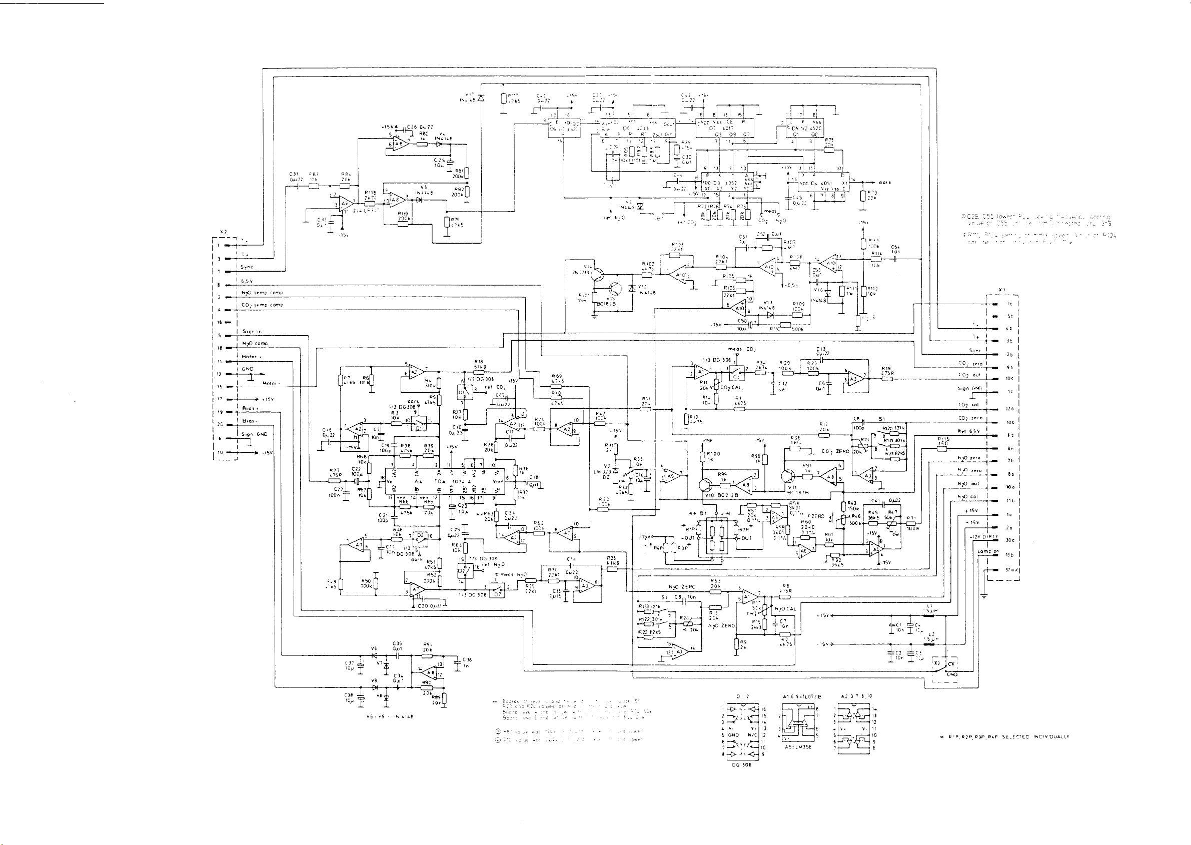
|
|
|
|
5
1esy
| i
|
2 | N70
+
1
|
1
4
| |
pom
|
|
ς
|
i
|
e
|
|
11
|
|
15
|
|
17
|
16 ! Bias
|
20 | Bras-
|
ε
10
Loco
temp
CO;
temp
Sign
in
N
comp
Motor
+
Sign
GND
comp
comp
+
-
Motor
+
15Y
15
+15V4
카크
he
ve
INS
GE
8|
13, 15[
Cc?
6
0422
Ve
RBC
IN
&168
Ve
>
144148
二
vee
vss
D?
4017
o:
ти
13)
Е
x Y
“DD
D3
x2
~
| | i
一
CE
os
31
4062
YI
OR
6?
10
YO
1
ATÉ
№5571
veg
ja
+
P
E
ps
|
i
as
—
01
al
el
1€!
」
πι
v2
alas
x
voc
;
8!
vss
4520
ac
3)
RI
PL
o
De
4051
гель С |
| | gl
La
ーー
vol
Е
x1
9
|
Å
m
ore
vi?
İNLİCE
RM
20k
u
6423
21k
:
22
301x
R22
625
サー レー
+
・
è
。
Е
2,
314?
4 |v-
SIGNO
sal
1
a
RS
2k
D:.2
--
<На
m6
L
GİS
У.
Y・|13
WIC)
pau!
ado
12
68
475R
-CI
NO
CAL
+
Ia
Te
в?
k75
+
AS:
U
LMISE
„15V
-15y
な
1
hdi
3 了 一
ave
sa.
eto
가
Ld
AZ3T
一
=
1
PN?
10k
AO
\ | 11
>.
‘90%
Rie
1Ck
le
12
10
9
Е
Che
107
上
>
тик
T
Tu.
τῷ
cor
一
|
4
Le
R15
180
Em
1
工
TS
eI
à
‘Sk
Les
10η
Зи
要
, ,
了
,
|
ヒーー
+
<
le
Sync
CO?
gere
CO?
out
Sign
GNO
CO2
cal
6602
2010
2
Ret
65V
270
we
N70
zero
M
LO
out
N20
cal
415v
-
15%
一
一
+12
1
=
L
一
сна
一
R'P_RIP_RIP_REP_SELESTEC
'
ome
be
rot
»
人
xi
="
+
vE
|
~
Se
|
em
it
|
3:
I
te
|
95
ve
|
~
ic
|
+
126
1
108
fe
t
Be
i
>
be
la
Mo
[
nb
|
~
la
一
2ο
HRT
Y
306
n
nb
INDIVIDUALIY
Page 75

DATEX
CARDIOCAP™
II
CG-SERIES
SERVICE
MANUAL
5-20
5.2.5
O,
measurement
The
oxygen
susceptibility,
gases
generally
measured
gap
in
and
off
A
differential
and
reference
within
The
pressure
rectified
a
DC
voltage
of
the
CAUTION:
construction
be
attempted,
circuitry
manual.
measurement
and
an
electromagnet
at a frequency
the
magnetic
is
with a synchronous
proportional
two
gases.
Due
and
which
the
pressure
inputs
any
is a
present
reference
due
field.
measured
to
the
service
and
therefore
layout
is
based
unigue
in a breathing
with a strong
of
approximately
gradient
to
with a sensitive
to
complicated
inside
of
the
property
gas
(room
is
forces
detector
the
oxygen
the
the
transducer
on
the
gas
air),
magnetic
165
generated
acting
and
partial
and
O,
measuring
detailed
is
paramagnetic
of
oxygen
mixture.
are
on
differential
amplified
sensitive
description
omitted
The
conducted
field
Hz.
between
the
oxygen
pressure
mechanical
unit
from
to
among
switched
the
of
all
gas
to
into
sample
molecules
transducer,
produce
difference
should
the
this
be
a
on
not
Differential
ino
out
一
一
pressure
transducer
X X
X x
XX
XX
*
XX}
XX}
|
X
X
X|
_—
Reference
Switched
magnetic
in
field
Sample
Mixture
Electromagnet
Figure
5.9
O,
measurement
principle
November
15th,
1990
Page 76

DATEX
CARDIOCAPTM
II
CG-SERIES
SERVICE
MANUAL
5-21
5.3
ECG
board
The
ECG
board
(approx. 1 mV)
circuitry
to
A/D-conversion
ECG
The
desired
input
input
patient
and
circuit
preamplifier
Defibrillation
Input
protection
is
established
patient
At
filter
serves
if
the
the
cable
input
(R22,
as
input
patient
R23, R28,
is
an
signal
the
lead
levels.
has a four
lead
configuration
input.
and
ESU
against
by
4.7
kohm/! W resistors
lead
and
there
is
limiter
connection
isolated
from
selector.
amplifier
the
The
position
protection
defibrillation
by
the
spark
also
the
electrosurgery
R29
and
and
provides
is
broken,
patient
signal
switch
and
pulses
gap
C6-C8)
input
(LEADS
that
accepts
cable
via
is
filtered
for
directing
(typically 5 kV/400
and
6800
F2.
interference
and a diode
amplifier
OFF).
the
the
protection
and
selecting
the
signal
uH
coils
circuit
saturation
low
level
amplified
the
into
the
in
each
(ESU)
that
bias
J)
The
patient
prevent
connected
for
high
static
across
voltages
components.
Amplification
Each
input
is
which
pulse
width
ECG
drive a differential
width
signal
modulator
modulated
across
isolation
frequency
the
which
amplified
signal
the
section
is
ESU
interference. A second
isolation
otherwise
by
standard
amplifier,
operating
drives
isolation
shielded
barrier
at
an
optocoupler
by a metal
to
allow a controlled
would
destroy
non-inverting
whose
output
approximately 5 kHz.
barrier.
that
enclosure
spark
the
isolation
amplifiers
is
sent
transmits
to
gap
is
passage
to
a
The
pulse
the
November
15th,
1990
Page 77

DATEX
CARDIOCAPTM
ECG
output
The
output
filter
demodulated,
CPU
board.
and
II
CG-SERIES
stage
an
adjustable
filtered
consists
50/60
and
SERVICE
of a pulse
Hz
notch
sent
to
an
MANUAL
width
filter.
analog
demodulator,
The
signal
multiplexer
low
on
5-22
pass
is
the
Leads
Input
rate
LEADS
a
produced.
These
optocoupler.
CPU
message
will
ECG
Isolated
(D1,
+/-12
off/Pacemaker
amplifier
pulse
OFF,
pacemaker
signals
board.
on
be
clipped
power
power
V24,
V,
using
is
detected
the
pulse
are
The
The
the
display
from
supply
is
V25
and
zener
pulses
saturation
by
the
INOP
output
is
detected, a fast
transmitted
signals
constant
generated
and
the
T!)
diodes.
are
ECG
the
caused
IN-OP
is a
across
sent
low
signal
output
waveform.
by a smal!
output
by a lead
comparators.
steady
(0.5 - 2
the
isolation
to
port C of
will
produce
data
string
100
of
which
off
or
by a high
In
case
low
voltage
ms)
low
barrier
the
8255
the
and
pacemaker
kHz
switching
is a regulated
of
state.
pulse
using
PPI
LEADS
converter
slew
When
is
on
pulse
an
the
OFF
November
15th,
1990
Page 78

DATEX
CARDIOCAP™
II
CG-SERIES
SERVICE
a
~
一
$
-
27
261
323
MANUAL
三
と
5-23
©
$ ©
5
는
e-
28
©
de
ca
co
Е
=
<
2
=
“E
<=
$
=
=
+
E
v5
È
5
a
_
a
pa
>
È
o
>
マ
ミ
ここ
つっ
= と て
Lio
DEI
VAN
č
m
5
È
이
mi
=
a
о
Figure
5.10
ECG
board
block
diagram
November
15th,
1990
Page 79

lil
|
©
-JVi
©
四
i
!
”
|
η
CE
.
!
이이
|
`
에
n
ΕΠ]
1
|
|.
(C)
e
|
||
1
上
|
|
|
|
I
|
e
바
,
>
=
=
>
В
+
|
=
==
||)
pr
に
|
|
~
|
E
・
|
i
=
р
-
°
|
ーーー
M
|
|
|
Ale
ak
=
-
|
-=
o.
2
.
li
4
nm
7
・
EL
fe
C
102,
Y
で
100.
ео
‘|
|
|
|
|
|
1
|
Page 80

DATEX
CARDIOCAP™
II
CG-SERIES
SERVICE
MANUAL
5-24
Figure
—
&
o
el
e
O
SKD
U
N
|
io
>
el
©
CD
u
trimmer
nalch
50/60H7
SO
An
LEE
Jvzs
NR
Y
DATEX
*
c24
R44
C22
R43
[
J
n
v5
v2
ct
CEN:
ase
(2
5
R46
n
<
ya
vi
5.11
ECG
board
parts
lavout
m
RS
LRze
[을
с?
A
?
|
As
Cie
|
|
Е
aS
[as
R34
vig
vie
vs
RIE
1832
e
о
Nile
ao
|
CIS
И
R16
ni
RIS
R14
R13
R12
Ja
그
|
-
っ
Y
Lt
7
二
到
>
MO
dese
D
ol
lo
Alo
本
Nonisolated
Isolated
OA
5
P/N
Ctri
side
side
880509
March
20th,
19
Page 81

DATEX
CARDIOCAPTM
II
CG-SERIES
SERVICE
MANUAL
5-25
5.4
IPT
(Invasive-Pleth-
Temperature)
The
IPT
board
one
temperature
1GS,
one
available.
The
boards
isolating
power
optoisolator/demodulator
The
two-pressure
waveforms:
1.
Either a plethysmographic
waveform.
2.
Invasive
The
single
plethysmographic
Temperature
is
pressure
have
switcher
pressure
invasive
designed
channel.
channel
two
common
channel
P2
channel
pulse
waveform.
or
board
to
support
However,
and
and
the
chain.
IPT
pulse
monitors
invasive
two
in
two
temperature
features
pulse
board
generates
or
invasive
will
pressure
pressure
models
with
width
display
channels
CG-1G
channels
the
ECG
modulator/
two
real
pressure
either
waveform.
and
CG-
are
board;
time
PI
a
and
the
The
temperature
of
which
output
and
Invasive
The
reference.
amplifier
power
are
The
a
connector
(pressure
is
the
is
amplified
linearization
pressure
monitor
supply
provides
The
IC.
The
on
transducer
compensated
Cardiocap
senses
by
providing a line
flag) by a pull-up
when a pressure
pressure
senses
the
flag
line
lines
is
signal(s)
patient
is
by
the
done
probe
+5 V excitation
excitation
the
IPT
for
by
software.
when a pressure
transducer
are
polled
grounded,
are
produced
(YSI
calibrated
by
software.
output
voltage
board
and
resistor.
is
plugged
by
the
pressure
400-series
amplifiers.
voltage
is
sent
is
sourced
all
sensor
on
each
The
into
the
multiplexer
by
voltage
thermistor).
and a ground
to a single
from
variations
has
connector
line
is
shorted
the
monitor.
display
divider(s),
Offset
adjustment
differential
the
isolated
in
this
voltage
been
inserted
that
is
to
The
and
when
is
activated.
part
The
held
ground
the
into
high
CPU
November
15th,
1990
Page 82

DATEX
CARDIOCAP™
Plethysmograph
The
optical
and
driver,
the
finger
picks
and
its
control
average
frequency
to
yield
up
the
peak
circuit
pulse
in
the
which
probe
II
CG-SERIES
plethysmograph
produce
attached
light
attenuated
value
is
sampled
adjusts
height
the
pleth
at
heart
pulse
the
pin
rate
waveform.
SERVICE
consists
300
Hz
to
the
patient,
by
the
and
filtered.
amplifier
7/A2.
range
The
(0.8 - 10
MANUAL
of
two
parts, a LED
50
us
infrared
and a phototransistor
digit.
This
light
An
automatic
gain
to
yield a constant
AC-component
Hz)
is
light
pulses
is
amplified
with
further
5-26
oscillator
to
that
gain
a
amplified
Signal
The
The
output
following
multiplexer
If a second
to
its
own
After
all
signals
are
demodulated,
multiplexer
signals
-
the
-
pleth
two
zero
pressure
control
pressure
pulse
width
are
resident
are
temperature
DC
pressure
and
+5 V reference
differential
is
is
provided,
modulator.
transmitted
low-pass
on
the
multiplexed
channel
flags
signal
provided
by
its
differential
across
filtered
CPU
and
board.
to a pulse
the
CPU.
the
isolation
transmitted
width
output
barrier,
to
modulator:
is
directed
they
the
analog
November
15th,
1990
Page 83

DATEX
CARDIOCAP™
II
CG-SERIES
SERVICE
MANUAL
5-27
の
9
go
oo
28
ele
|
TE:
U
a
<
Е
3
LE
<
gran
Le
Cphral
u
ct
St
S
©
ーー
ニー
I
つら
Li
[Е
と
Figure
ши
СЕ
α
95ο
a
o
>
v
a2
E
ЕЕ
の
と
=
3
<
at
»
5.12
는
Е
=
<
È
=
IPT
board
block
diagram
(CS,
2CS,
2G,
2GS)
November
15th,
1990
Page 84

DATEX
CARDIOCAP™
II
CG-SERIES
SERVICE
MANUAL
5-28
Figure
5.13
IPT
O
board
[TA
P/N
Ctrl
parts
877781
layout
(CS,
2CS,
2G,
2GS)
CC
2F
972879-4
(Connectors
both
X3
and
X4
not
included
in
CS
model)
November
15th,
1990
Page 85

『
©
DATEX
CARDIOCAP™
I]
CG-SERIES
SERVICE
MANUAL
nw
n
FRCITATION
EXDITATIIN
Figure
_
VOLTAGE.
VOLTAGE: 一 上
„ED GND
LED 一 -
Р.ЕТН
IN
PLETE
GND
TNYBPF.G
xa
> 一 一
L
o
i
È
と
=
we
—
QI
-一 十 -一
o
5.14
一 一 一 一 一 一 -一
+
IPT
connector
diagrams
ο
Ш
55
la
(CS,
|
board
2CS,
TEMPERATURE
TEST
RB9
AL
Ms
and
2G,
-
SWITCHE
51
の
IPT
2GS)
Rge
~ 一 一
г
||
board
ет
|
i
1
|
|
po:
schematic
A
EI
ita
|
АРЕН
1
|
;
;
:
j
ХЕ
E
1
——
>
了
τε
E
ーーーーー ジ ーー
TEPTİ
‧ 一 一 一 一
pee
FOND
TAVEPF.52
=
ENT
一;
P-
©
ev
RES
P_ENTK
PENTE
PJETH
f3ND
-
OUT GND
OUT
{м
SND
IF”
uni:
8775085
ХЗ
and
X4
ore
not
IP"
uni:
877506
X4
is
not
connected.
connected.
November
15th,
1990
Page 86

E_LSE-
WIDTH
MODULATOR
114]
Plettin
|
vi
N46
£
45
y
TEMS
INVBP
Ge
1020
AMPLIF
Y|-12V
AMPL
ERS
SAMPLE E HOLS
RIS
Invoz/lg2
dert
«5,
ref
>.
Pleth
Pie
invbp
7
i
|
3
dc
73
5
Δ΄
Ru
20K
I
MUX
CHANNEL
SELECT
Vig
2N3904
RL
LE
|
+5V
V2E
2x9V1
v26
R64
Z2k)
{
)
」
“3
¡Pletr
out
qna
3|Pa
I
DE
-REFLECTION
‘DUAL
INVBP
AMPL
G=1020
INA
Ab
107
INTEGRATOR
TIME
CONST}
MVA
STLATET
wi
POWER
Diy
SUPPLY
BİL
RE3
100K
V23
20
390%
é
AA
R76
VIZI
24390.
V22
2N390。
R69
Tük
RIO
r
D
>
Page 87

DATEX
CARDIOCAP™
II
CG-SERIES
T
SERVICE
MANUAL
5-30
3
Sw
72
tI
-I
ЕЕ
vs
rs
7
で
18
ウーーーーーーー
σ
их
33
N
Í
=
σσ
a 三
+=
+
TEST
TEMP
SWITE
=
cr
:
i
ご
<
= >
až
EZ
sč
Ln
2
Ls
t
=
o
+
sč
£
<
sync
$
で
©
=
=
È
ュー
=
-
—
5
14
=
tra
Figure
5.15
IPT
board
block
diagram
(1G,
1GS)
November
15th,
1990
Page 88

DATEX
CARDIOCAP™
II
CG-SERIES
SERVICE
MANUAL
5-31
Figure
5.16
IPT
board
P/N
-|
Ctri
parts
877782
layout
(1G,
1GS)
CZ
2F
273906-
4
P/N
877871
Ctri
November
15th,
1990
Page 89

1
1)
e)
DATEX
CARDIOCAP™
11
CG-SERIES
SERVICE
MANUAL
'n
EXETTATION
EXCITATION
YL
AGE
VOLTAGE.
coon
BLETH
πα
ТРЕ
bro
P-
LDL
IN
LE
DE
СВ
Figure
ed
Wf
ー
O
5.17
—
ーー
_
IPT
connector
diagrams
LL
(1G,
TEMP,
R82
318
board
1GS)
TEST
and
SWITCH
RES
1K
IPT
board
OD
İL
Lj
schematic
3
4
ュー
2
LIEU
|
Е
2
;
1
Pla
Pi-
PcND
ЕЕ
elini:
PLENT-
ti
ou:
où:
öne
November
15th,
1990
Page 90
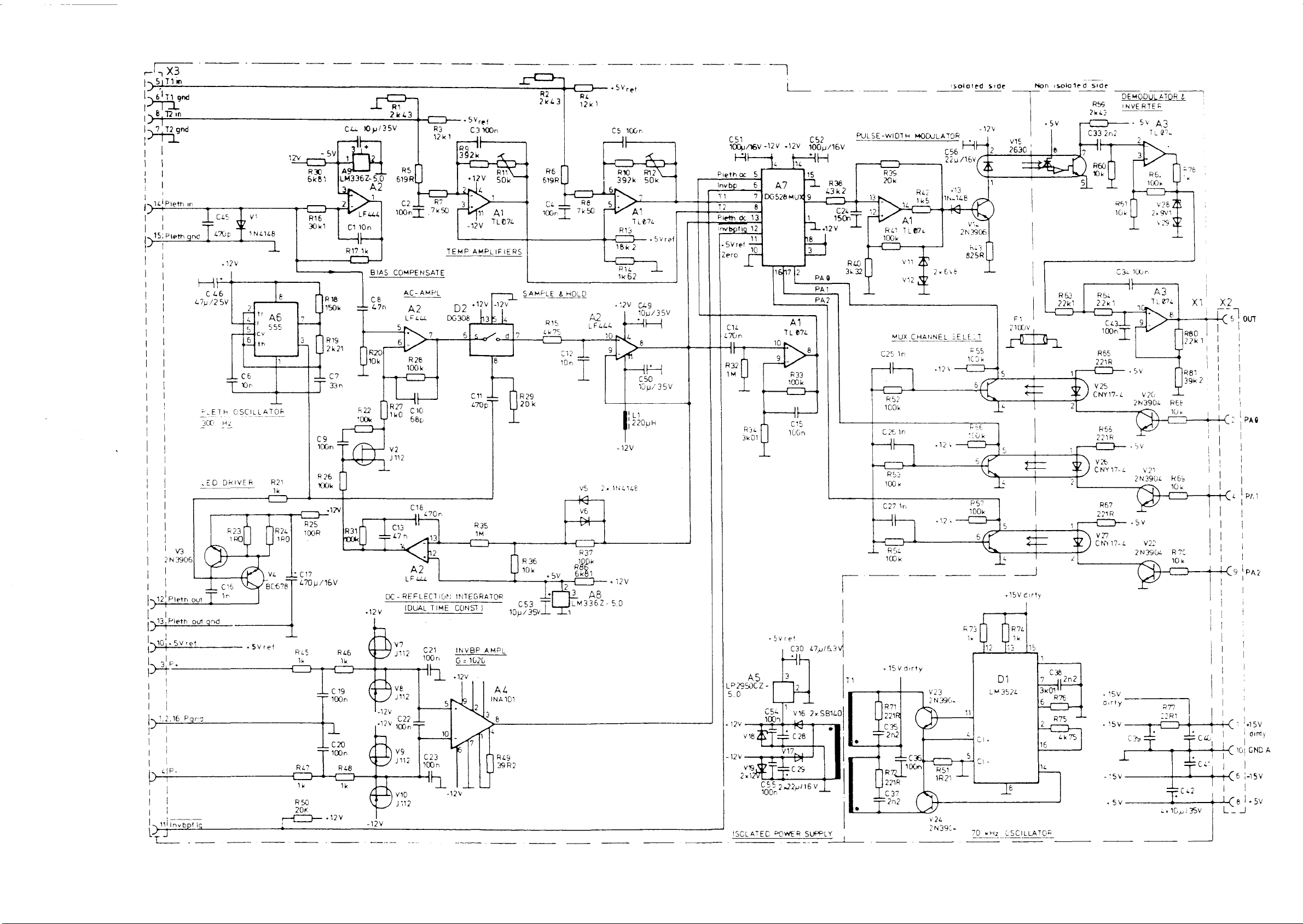
1551710
gnd
elmi
|
DĚ?
72
7
|
コ
|
ワイ
|
|
|
|
|!
|
po
+
Рен
py
|
|
Pieth
15:
|
|
|
|
|
M
|
|
|
|
|
|
|
|
|
|
|
|
‚|
|
|
|
|
|
|
pol
|
|
|
|
|
|
|
|
|
|
|
|
|
|
|
|
|
|
|
ya
|
283906
]
|
|
pol
|
Pleth
12
|
|
D+
;
Lag!
SV
O,
|
ale
I.
p
|
|
12.16
NS
[
D
M
1
1
|
DET
|
|
|
|
|
1.、mlinvbpt
ybpf
L
и
né
474
LED
out
ref
Pars
ng
lc
ls
tos
4706
|
E
cs
/2
ПЕ
|
PLETE
Hi
30
n
DRIVER
and
Jv
Y
14148
|
ーー
ον
raat
r
с,
TA
66
1.
To
OSCILLATOR
ーーー
|
„Sv
8
Ab
555
7
T
RZ
Ik
1
rer
ーー
u
wey
C17
に
L70p/16V
一
一
Rus
ik
27
R
ik
R50
20K
ゴー
-
6830
6681
这
Dün
R26
700k
R46
100n
|
1
C20
100n
・12Y
ον
р
10p/3
Coe
—
+
3
1
|A9
|LM3362-50
A2
BIAS
ce
4
7η
R20
"0K
R
ην
oo
vi
DC-R
DC-
a12w
(
р
N
“DV
2,
+1
R48
ik
(m
Jan
q
dv
RI
kr
6196
joon
RS
C2
R3
Dr
R7
.7k50
year
COMPENSATE
LME
Α2
Les,
LF
。
DE
512
næ
R27
Ee
p
J112
A2
ale
LE
REFLECHOM
IDUAL
2
ju
8
J112
022
ーー
ET
v
J112
A2
4
v10
D2
06308
一
с
,
INTEGRATOR
CONST)
TIME
N
INVBP_AMPL
ÖZ
G =
』
Lai
SN
0).
|C23
soon
4
1
A
2v
ref
„by
e
A
上
R
1204
Ae
|
|
sv
ab
5
d
cn
crop
835
}
ONST
1020
|
3
7
[一
一
一
160%
ens
SAMPL
a2v
|
sa
5
=
—
R29
20k
36
R
10k
C53
av.
ron
AL
101
INA
|
4
Rio
<
R2
PROS)
2
È
619R
Ce
πα...
HOLD
&
MELE
RIS
PS
小
012
10n
«SV
Tr:
1
=>
LM336
CI—
RL
12k
R8
A2
I
vs
44
VE
>
537
ayer
P
Le
AB
+5
e
+5Vret
100
CS
q”
o
εν
RX
392k
6
7
7
5;
A
674
Ti
ME
com
+
Rig
162
C9
.:2V
10p/35V
HA
né
10
È
9
AT
A
C50
10
|
1220pH
-12V
ὃν
P
Ls
DANCE
a4
2-50
一
k
|
|
sue
35V
y
-12V
5
É
7]06528M
B
|
>
1
—
(O
上
|
—
R:
34
3k01
+5Vref
css
10071
TT
BY
vie
YS
JE
C55
πω
一
+12V
4
A7
167
TL
10
?|
3
|
。
=e
V17
2,22
.
|
ς
AH
14
15
|-
M
1
E
2
ma
E
A1
0%
8
R33
200k
I
JL
it
015
ο
00n
2
2758460
VI
C28
se
っ
μα...
PA
PA2
-一
一
GI
1004/16v
6
p
r-
bp
2
12
&
Pen
7
fome
|
„SY
Zero
cu
on
lf
R32
mM
Pod.
5.0
12V
+
-
12V
ex
ISCLATEC
POWER
SUPPLY
PULS
PUESE
nov
#38
43k2
o
18007
u
|
VŠ
1
|
°
1
-WIDTH
MUX
in
C25
十
一
(一
RS?
100k
加
M
ゴー
ーー
—
653
κ
100
tn
C27
SE
ーー
ーー
RS
aL
k
100
dirty
ISV
MODULATOR
C56
AA
14-348
EVE
2x
CHANNEL
4
SELE,
my
„OK
my
izi
|
V24
2N39C-
|
ed
solat
-12Y
7
3
213806
i
8258
πες
Wok
-
Ho,
5
το
4,
A
<
R57
A
6
-
,
side
上
ご
T
5
T
No
=
|
=
<
=
Sven
1
isolated
wer
с
i
mm
1
Y)
2
4
1
Я)
2
1
Y
‘
side
RSS
quis
cn
vie
RSS
2218
>
17-14
CNY
R67
ビー
vo
CNY
DEMODUL
SETS
17-
6
:
ATOR
АЗ
SV
+
Te?
wae
2N3904
SV
2
ум
2N3906
.5V
っ
va
2439
4
”
REE
We
RES
10k
RIC
ida
1
|
|
1
|
|
|
|
|
し
|
!
\
ice!
218
ao
|
|
i
|
|
|
a
|
||
om
=
|
|
|
|
|
」
|
m
기
Po
|
9
|
|
.
=
oi
|
|
|
|
|
|
Ao
1
i
:
:
!
|
|
.
Page 91

DATEX
CARDIOCAP™
II
CG-SERIES
SERVICE
MANUAL
5-33
5.5
5.5.1
NIBP
NIBP
PNEUMATIC
measurement
board
SYSTEM
The
-
Pressure
-
Bleed
-
Exhaust
See
diagram.
Pressure
The
cuff.
and
NIBP
board
transducer
system
valve
Figures
piezoresistive
It
the
5.19
transducer
measures
pressure
consists
and
pressure
the
of
20
for
transducer
absolute
the
NIBP
fluctuations
following
board
pressure
caused
parts
(B!)
of
by
arterial
pneumatic
layout and
is
connected
the
blood
wall
parts:
schematic
to
the
pressure
movement.
cuff
Bleed
Bleed
valve
system
valve
is
pulse-width
pulse-width
valve
is
open
constantly
signal
Exhaust
Valve
frequency
valve
Y1
is
(Y2)
ratio
low
used
all
and
releases
controlled
is
100%
the
time.
the
valve
is
40
Hz.
as
an
exhaust
the
the
When
cuff
between
signal
the
is
closed
valve
pressure.
100%
is
constantly
ratio
all
the
to
quickly
is
The
and
0%
time.
opening
0%.
high
the
signal
The
deflate
of
the
When
and
the
is
driving
the
cuff.
the
November
15th,
1990
Page 92

DATEX
CARDIOCAP™
II
CG-SERIES
SERVICE
MANUAL
5-34
ANALOG
CIRCUITS
Pressure
The
source.
that
amplifiers
difference
producing a current
transducer.
transducer
pressure
This
is
produced
ASA
through
The
X6/5).
Differential
The
output
between
(TP
X8/2,
(operational
and
15)
amplifier
of
the
X8/3).
amplifiers
that
excitation
transducer
is
produced
by
and
excitation
the
midpoints
This
produces a gain
BI
by
the
voltage
ASB
resistor
of 4 mA
pressure
of
signal
A4A
are
voltage
the
is
excited
floating
reference
used
as
RS
(TP
X8/7,
through
of
transducer
pressure
is
fed
and
A4B,
of
31.1
by
a 4
mA
constant
constant
voltage
the
Bl
Bl
sensing
voltage
diode
V7.
Operational
followers.
X8/8)
resistor
is
is a differential
about
is
1.200
for
12 V (TP
resistor
to a differential
and
(TP
resistors
X8/4).
R12,
current
of
1.200
The
voltage
V,
the
pressure
X8/8,
signal
bridge
amplifier
13, 14,
V
legs
Pressure
At
zero
zero
pressure,
transducer
compensated
stage
is
an
filtering.
The
next
stage,
adjusted
pressure
produced
Pressure
The
pressure
a 5 V
the
with
transducer
DC
DC
channel
of
range
voltage
throughout
converter.
and
gain
the
BI
may
for
by
inverting
A4D,
trimmer
channel
is
the
blood
(0
to
-5
range
to I V
control
output
be
up
R6
(TP
amplifier
is
an
R11.
gain
differences,
the
transducers
range
used
to
pressure
V).
This
(+0.755 V to
voltage
to
100
X8/5)
with
inverting
The
and
measure
cuff.
voltage
difference
mV.
in
unity
amplifier
gain
so
range
bias
circuits
the
The
This
zero
the
amplifier
gain
is
adjusted
that a linear
(TP
static
or
static
is
sent
to
-0.755
volts)
of
the
pressure
pressure
and low
whose
to
X8/6).
voltage
stage
A4C.
pass
gain
can
compensate
signal
is
non-oscillating
signal
A2A
from
which
for
the
A4D
A/D
is
This
be
for
has
limits
November
15th,
1990
Page 93

DATEX
CARDIOCAP™
Two
input
the
DC
depending
cuff
pressure
A2A
is
corresponds
If
the
cuff
through a voltage
5
of
the
by
the 1 volt
is
referenced
and
+382
To
allow
zero
points
mmHg
respectively.
II
CG-SERIES
ports
of
channel.
sent
The
on
the
cuff
is
between 0 and
directly
directly
pressure
divider
multiplexer.
signal
to
ground
mmHg.
for a certain
are
actually
SERVICE
the
analog
microprocessor
pressure
to
the
multiplexer
to
the 8 bit
exceeds
255
network
This
doubles
and
since
the
the
pressures
amount
set
at 0 to
MANUAL
multiplexer
selects
required
255
mmHg
port
range
of
mmHg,
(R30/1-2
the
pressure
voltage
represented
of
zero
pressure
235
mmHg
(A3)
the
for
best
the
signal
6,
because
the
A/D
the
signal
and
range
measured
drift,
and
are
dedicated
desired
resolution.
produced
the
converter.
is
directed
R30/3-4)
represented
at
the
are
between
the
-108
port
pressure
to
divider
pressure
to
362
to
If
port
-128
5-35
the
by
Pressure
The
AC
the
processor
are
used
additional
second
order
component
is
the
amplifier
third
stage
stages
AC
During
signal
P16
(TP
reset
cuff
is
from
AC
channel
component
to
analyze
as a basis
amplifier
high
of
the
stage
A2D
blocks
X9/4).
inflation
sent
to
ground
the
processor.
filters
of
the
the
for
blood
is
AC
pass
filter
pressure
(G = 73)
the
or
if
through
cuff
pressure
small
pressure
coupled.
to
effectively
data
(TP
and
offset
an
abnormal
D6A
data
cuff
pressure
determination.
The
first
block
X9/2).
low
pass
voltages
of
situation
and
D6B
is
amplified
fluctuations
stage,
out
The
second
filter
(TP
the
previous
arises,
with
This
A2B,
the
X9/3).
AC
to
allow
which
is
a
DC
stage,
two
the
AC
reset
A2C,
The
signal
November
15th,
1990
Page 94

DATEX
CARDIOCAP™
AC
channel
The
output
through
division
multiplexer
the
following
The
processor
incoming
of
the
28).
chain.
A/D
II
CG-SERIES
range
selection
from
A2D
The 5 outputs
The
(A3).
If
outputs
selects
signal
level.
converter
is
connected
of
division
voltage
have
voltages
the
proper
This
effectively
from 8 bits
SERVICE
this
ratio
is
at
the
division
to
MANUAL
to a voltage
resistor
selected
beginning
1/2,
chain
1/4,
ratio
extends
12
bits.
divider
make
by
the
of
the
1/8
and
according
the
chain
up a binary
analog
chain
1/16
to
dynamic
5-36
(R24
is | volt
volts.
the
range
Multiplexer
The
analog
AC
channel
used
to
select
previously,
channel
has 5 different
according
INPUT
0
AC
component
1
2
3
4
5
6
7
DC
(not
"
*
"
"
component
"
in
and
A/D
multiplexer
to
the
A/D
suitable
the
DC
channel
to
the
following
DESCRIPTION
use)
converter
circuit
converter.
ranges
has
ranges.
table.
DIVISION
1/16
1/8
1/4
1/2
1/1
1/2
1/1
---
A3
for
two
The
is
used
The
same
both
channels.
different
multiplexer
to
RATIO
select
either
multiplexer
As
described
ranges
and
inputs
the
is
the
are
DC
or
also
AC
allocated
The
operational
(G = 6.62),
level
(TP
X9/5).
+5 V range
successive
its
own
internal
by
the
external
200
us.
The
ADCRD-signal
signal
when
amplifier
which
to 0 - 5 V
approximation
amplifies
Resistor
clock
RC
circuit
converted
is
activated.
A15
and
RD-signal
A1C
network
for
the
A/D
(TP
X6/2),
(R29,
signal
is a non-inverting
the
incoming
R30/5-6
A/D
converter.
the
C34),
is
led
Decoder
are
converter
to
signals
The
conversion
conversion
buffer
D5
activates
active.
and
7-8
Ul.
converter
rate
D13
gain
to
-5 V to
shifts
Ul
is
time
output
the
ADCRD-
stage
+5
the
is
an 8 bit
is
timed
determined
is
about
when
November
V
-5
to
by
15th,
1990
Page 95

DATEX
CARDIOCAP™
II
CG-SERIES
SERVICE
MANUAL
5-37
JUMPERS
Reference
The
reference
and
operational
are
typically
The
NIBP
Jumper
adjusted
changed
Jumper
PIN
1-2
2-3
voltage
voltages
amplifiers
+5.30 V (TP
board
X13
contains
selects
to 5 minutes
to 5 seconds
X10
selects
source
are
the
(no
(X13
the
generated
A5C
and
X6/4)
two
watchdog
jumper).
RAM
and
jumpers.
time.
In
short-circuited).
memory
RAM
CAPACITY
32
kbytes
8
kbytes
with
the
A5D.
The
-10.6 V (TP
Normally
test
purpose
capacity
SELECTED
reference
reference
X6/5).
the
time
the
time
used.
diode
V6
voltages
is
can
be
PUMP
SAFETY
AND
CIRCUITS
VALVE
The
magnetic
collector
(+15
V)
(VI,
V3),
circuits.
Pressure
A
comparator
reference
zeroing
DRIVERS
valves
darlington
is
used
controlled
The
watchdog
control
circuit
level.
the
watchdog
to
drive
switch
If
cuff
and
driver
these
by
the
timer
AlA
is
circuit
the
air
pump
circuit
circuits.
processor,
are
D11. A separate
An
connects
prevents a prolonged
compares
inflated
(TP
cuff
the
circuit
X9/6).
controlled
power
additional
power
inflation.
pressure
to a fixed
prevents
by
the
source
power
to
valve
CPU
open
switch
from
November
15th,
1990
Page 96

DATEX
CARDIOCAP™
II
CG-SERIES
SERVICE
MANUAL
5-38
PROCESSOR
Watchdog
The
watchdog
magnetic
not
connected.
connect
the
which
CIRCUITS
The
circuits
resides
(RAM).
operations
Port
NIBP
Memory
The
zero.
ADDRESS
0000 - 7FFF
8000
power
cuff
will
NIBP
to
in
Ports
P3
also
data
organization
code
The
-
timer
timer
valves
The
is
inflated,
deflate
board
allow
D2
(EPROM)
P3
of
the
provides
to
the
memory
decoded
RANGE
circuit
and
the
CPU
to
the
pump
the
CPU
the
cuff
contains
independent
and
and
Pl
NIBP.
RS-232
main
CPU.
and
the
address
(D8,
D9)
air
pump.
is
able
only
after 5 minutes.
its
own
the 8 kbyte
are
used
external
space
FUNCTION
32
A/D
Normally,
to
reset
when
cannot
8051FA
operation.
to
control
output
data
is
64
kbyte
external
converter
controls
the
the
cuff
control
CPU
The
data
which
memory
kbytes.
the
power
power
watchdog
is
not
the
watchdog
and
64
kbyte
memory
directly
is
used
both
data
memory
to
the
circuit
inflated.
memory
code
in
various
to
transmit
start
of
the
valves
and
circuit,
memory
D3
from
is
If
CPU
Control
CPU
ports
functions.
PORT
P
3.0
P
3.1
P
32
P
3.3
P
3.4
P
3.5
P
3.6
P
3.7
P3
P3
ports
and
Pl
are
used
to
directly
FUNCTION
RXD/
TXD/
Mux
address
Mux
address
Mux
address
15 V power
WR/
RD/
control
0
}
2
sense
several
NIBP
November
15th,
1990
Page 97

DATEX
CARDIOCAP™
PORT
ママ
ママ
で
で
で
で
Reset
The
reset
guarantee
down
II
CG-SERIES
Pi
こら
らい
ょ
ひい
ひい
っ
circuit
line
is
simultaneous
conditions.
connected
resetting
SERVICE
FUNCTION
Shunt
Shunt
Exhaust
Bleed
Pump
Watchdog
AC
+15 V power
valve
valve
valve
control
reset
to
the
common
with
MANUAL
I
II
valve
reset
the
control
reset
main
line
RESET
processor
at
5-39
to
power
TEST
POINT
SIGNALS
PIN
X8/1
/2
/3
/4
{5
/6
/7
/8
SIGNAL
AGND
Differential
transducer
Differential
Used
for
Used
for
Voltage
pressure
(4
difference
mA = 1.20
output
output
pressure
pressure
transducer
V)
of
pressure
(A4)
output
zeroing
gain
adjustment
depending
current
on
November
15th,
1990
Page 98

DATEX
CARDIOCAP™
II
CG-SERIES
SERVICE
MANUAL
Gli,
DATA
5-40
DIAGRAM
RLOUK
МИ?
Net
АНТ
ИН
TON
DRIVER
CARLING
VALVE
SAFETY
Pi
—
— — — ーー
z
i
=.
こ
ЕЕ
r
e
=
Е.
ポー
i!
|
TE
ーーーーーー
г
|
Ger
PRE
ER RI
(
FUP
E
ANNE
OUT
Figure
5.18
Block
İn
all
are
used:
which
Diagram
other
one
contains a built-in
of
NIBP
versions,
for
standard
two
System
different
adult
choke
(USA
kinds
cuff
for
Version)
and
infant
of
twin
another
cuff.
May
15th,
hose
1991/1
Page 99

DATEX
CARDIOCAP™
1i
CG-SERIES
SERVICE
MANUAL
5-41
schematic
layout
NIBP
Figure
Program
Eprom
5.19
(part
board
1)
parts
and
diagram
7
: | RXDATA
— =
|
|
|
|
E 7
A
一
|
8
5
1
D
E E
ECGSYNC
F
。
|
4
圖
I I
çı
у
—
47
:
|
| |
1 |
İS
qto
RXD
E
7.
3728MHz
22
.
Ls,
M
199N 1 |
40
TALI
3
RST/VPD
1853 9 RxD
3.1
TXD
3.2
INTE
3.3
INTT
3.4
18
3.5
11.
NR
3.6
3.7
8
0
1
2
3
4
5
6
7
8 | 9
9
10
11
12
>
XTAL2
ALE
PSEN
Абак
128
P2.8
P2.1
P2.2
P2.3
P2.4
P2.5
P2.6
P2.7
3
53
|
7
|
,
Ξ Ξ - 3 3
v2
an
Аа
4X1K9
「
+
」
一
R36
ーー
ナー
XX19K
„W
RESET
Est
x
17A
|
A
|
=
8
c
|
|
D
|
|
F
6
.
|
|
ID-
code
876963
Control
no
i
J
py
K
LI
,
L
7
TEST
|
to
14 ~ 一
—
N
ーー
一
一 一
一 |
」 |
|
TEST
o
‘
i
:
i
=
2
98
peta
21
06
90
6.03.98
WE
è
| |
05,
05
TEK
T
1
Las
LT
“3.3.
č“
СКС
Te
ENE
0040K0
T T
5432
|
24
2178
[4899
4940
WUUTOS
: 3
000
74HC139
|
073
-2
Ao
ct
VERKKI
DATEX
и’.
—
4
ὃν
;
INSTRUMENTARIUM
4 5
1
|
|
|
|
i
|
一
JI
4101
00
"o: 9 89 09
611
.
LUE
sro
ON
Lera
..
το
ivy
1.3
SNDD
.
ー
δὲν
-
-
44)
가
SITE
W-
|
i
|
+
| |
|
cas
+
ーー
十
on
地
è
+
|
ーー
rep
BOARD
TARK
é - 2 3
ーッ
一 一 ---
cal,
==
eu
+
pe
T
+
mm
ik
o
—
300
iL
一
194
7
ーー
IM
3B
ー
ーー
Xi
x
X1
X
XI
XI
이
876920-3
|
y
|
ca
2A
304
324
290
sx
|
K
L
—
M
|
N
;
|
|
>
_
А
November
15th,
1990
Page 100

DATEX
CARDIOCAP™
II
CG-SERIES
SERVICE
MANUAL
5-4la
.
Figure
Program
Eprom
5.19a
876963
P/N
Ctrl
NIBP
(part
board
(board
1)
layout
parts
modification
ㆍ
level
schematic
and
.
ㆍ
5
.
and
.
diagram
ㆍ
higher)
a
т
A
|
B
2
|
|
|
| |
!
|
| |
|
|
|
| |
2
:1
一
一
人
i
|
|
|
+5Y
一 + 一 一 +
AA,
19
3 4
7.3728WH2
yil)
—
e
i
een
J
20
lun
-
二
一
e — ——
8
03
ro
i
i
È 5
iile
1
4X1K6
i
у
С
4
1
BC182
e
L
236
ーー
XT
0K
es
2
RESET
7
3
T
9
x!
MA
-
! |
re
|
|
г
o
トー
È
EC6SYNC
H,
『
E
c
トー
À
ーー
1
:
—
ry
г
κ
|
」
i
|
|
|
==
R44
X
E
c9
=
του]
soul,
“和
于
OS
1 |
IA
+
xi
1C
vi
2x
X
1
304
|
|
1
!
|
i
,
|
I
|
|
|
|
|
I
|
i
I
|
i
|
|
|
|
|
|
|
|
I
1
|
I
|
|
|
|
1
|
1
1
1
|
|
|
|
|
I
|
1
|
|
|
|
|
|
|
|
I
i
|
|
|
|
|
|
|
|
|
|
,5Y
9
| , て
=
T
173
-
gt
No
τοῦ
uy
-
141
=
19U|
ALTE
CH
.
+
—
O
©
SH/CG
-
JB
+
TEST
N
x7
4
|
:
3
i
=
12.02.01
:4
08.
9OLEJ
21.86.90
MUST,
è
May
ISth,
1991/1
| |
]
EN
9S
|
TERK
GATO,
15 8 90400]
s.s.gevoko
DITES
x
|
5786
- )
5432
|.
570
MUUTOS
:
2 3 4
-4
-3
-2
WERKKI | INSTRUMENTARIUN
DATEX
+
-=
=
|
:
i |
|
|
"NIMI
0°
|),
99.89
5 5
|
+
'
à
=
don
Leiden
圖
NIBP
30ARD
| i
OSI
TARK
т
+
+
нуу
7 3 3
Poty
|
SIVU
X1
324
KI
2940
100
xi
320
876920-4
ㅣ
|
|
|
|
|
 Loading...