

Page 1
MAC5
GEBRUIKSAANWIJZING
USER MANUAL
Page 2

Page 3

NL
Dateq MAC5 Handleiding Veiligheidsinstructies
2
Veiligheidsinstructies
1 Alle veiligheidsinstructies, waarschuwingen en gebruiksaanwijzingen moeten als eerste
gelezen worden.
2 Alle op het apparaat aanwezige waarschuwingen dienen opgevolgd te worden.
3 De gebruiksaanwijzing dient opgevolgd te worden.
4 Bewaar de gebruiksaanwijzing voor toekomstig gebruik.
5 Het apparaat mag nooit in de onmiddellijke nabijheid van water worden gebruikt; voorkom
de mogelijkheid van binnentreden van water en vocht.
6 Het apparaat mag alleen geplaatst of gemonteerd worden op de door de fabrikant
aanbevolen wijze.
7 Het apparaat moet zo geplaatst of gemonteerd worden, dat niets een goede ventilatie in de
weg staat.
8 Het apparaat mag nooit in de onmiddellijke nabijheid van warmtebronnen zoals
verwarmings installatie delen, kachels, en andere warmte producerende apparatuur (onder
andere versterkers) worden geplaatst.
9 Sluit het apparaat alleen aan op de juiste netspanning door middel van de door de fabrikant
aanbevolen kabels, zoals beschreven in de gebruiksaanwijzing en/of vermeld op de
aansluitzijde van het apparaat.
10 Het apparaat mag alleen worden aangesloten op een wettelijk goedgekeurde
(rand)geaarde netspanningsaansluiting.
11 De netspanningskabel of het netspanningssnoer dient zo gelegd, dat er redelijkerwijs niet
overheen gelopen kan worden of geen voorwerpen op of tegenaan geplaatst kunnen
worden welke de kabel kunnen beschadigen. Speciaal moet rekening gehouden worden
met het punt waar de kabel vast zit aan het apparaat en waar de kabel vastzit aan de
netspanningsaansluiting.
12 Voorkom dat vreemde voorwerpen en vloeistoffen in het apparaat kunnen binnendringen.
13 Het apparaat dient op de door de fabrikant aanbevolen wijze gereinigd te worden.
14 De netspanningskabel of het netspanningssnoer dient, indien voor langere tijd het apparaat
niet gebruikt wordt, uit de netspanningsaansluiting gehaald te worden.
15 In alle gevallen, wanneer er na een gebeurtenis gevaar ontstaat voor onveilige werking van
het apparaat, zoals:
· na het beschadigd raken van de netspanningskabel of het netspanningssnoer
· na het binnendringen in het apparaat van vreemde voorwerpen of vloeistoffen (onder
andere water)
· na een val van het apparaat of een beschadiging van de behuizing
· na het opmerken van een verandering in de werking van het apparaat
moet het gecontroleerd worden door daarvoor bevoegd technisch personeel.
16 De gebruiker moet geen werkzaamheden aan het apparaat uitvoeren anders dan die in de
gebruiksaanwijzing staan omschreven.
Page 4

3
Introductie Dateq MAC5 Handleiding
NL
Dateq MAC5
De DATEQ MAC5 is een zeven kanaals 19-inch powered mixer die met name toepasbaar is in
cafés, dansscholen, zalencentra etc. De MAC5 is uitgerust met drie microfoon-ingangen waarvan
er twee naar line omschakelbaar zijn. Verder zijn 4 stereo line ingangen aanwezig.
Kanaal 1 heeft een talk-over circuit zodat de aangesloten microfoon altijd goed verstaanbaar is.
Deze schakeling reageert op het aangeboden microfoonsignaal (voice activated) en zorgt ervoor
dat dit signaal voorrang krijgt op de andere signalen. De talk-over functie kan met een schakelaar
op het front worden in,- en uitgeschakeld.
Er zijn twee uitgangszones beschikbaar (de actieve master A, en passieve master B) met elk een
tweevoudige toonregeling, een balans-instelling en een volume-regelaar.
De versterker uitgang van master A is met NL4 connectoren uitgevoerd. De passieve uitgang B is
voorzien van asymmetrische cinch connectoren.
Produktondersteuning
Voor vragen over de MAC5, accessoires en andere produkten kunt u contact opnemen met:
Dateq Audio Technologies B.V.
De Paal 37 Telefoon: (036) 54 72 222
1351 JG Almere Fax: (036) 53 17 776
Nederland E-mail: info@dateq.nl
Internet: www.dateq.nl
Page 5
NL
445 mm
Dateq MAC5 Handleiding Installeren
Inbouwen van de MAC5
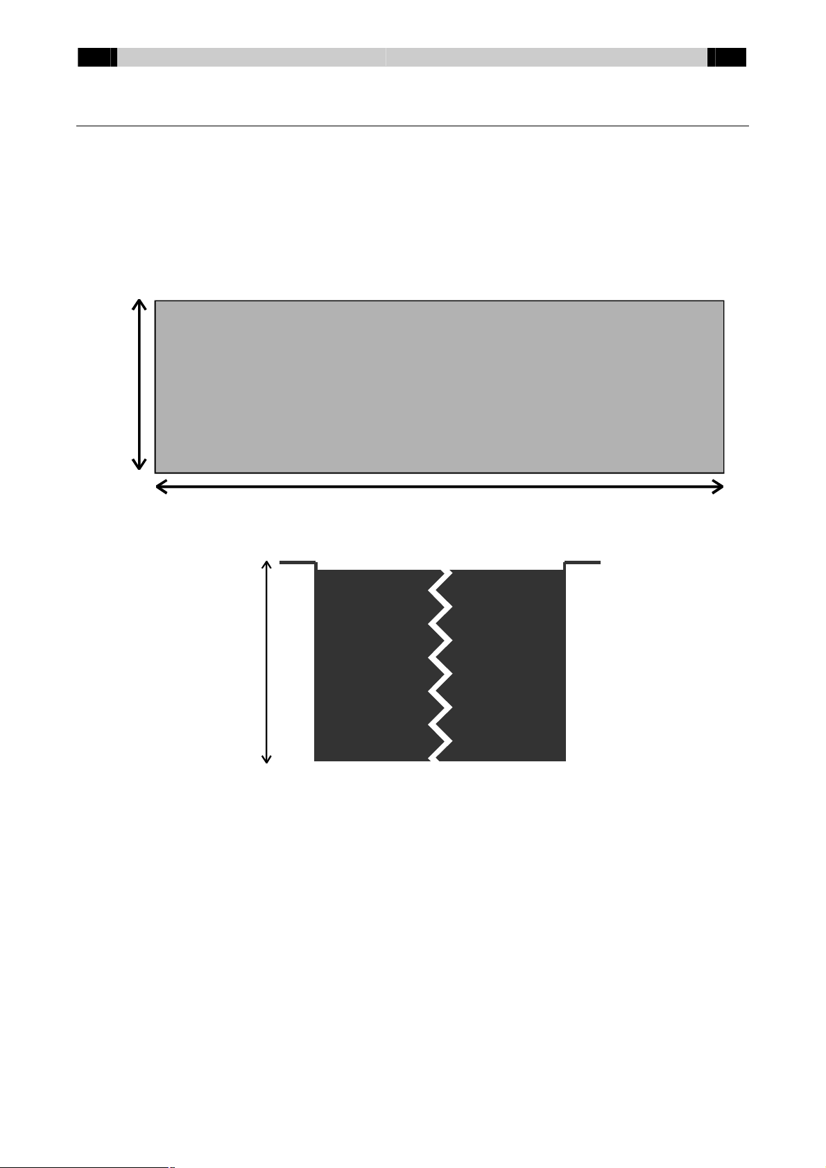
De MAC5 is ontworpen om te worden ingebouwd in een 19-inch rack en is 3 eenheden hoog
(132mm). De kast past in een opening van 445 x 132 x 210mm (B x H x D). Zie ook de
maattekeningen hieronder.
De 19-inch drager heeft een dikte van 2mm. Houd bij het inbouwen rekening met het uitsteken
van connectoren en pluggen aan de achterkant van de MAC5!
Aan de zijkanten zitten ventilatiegaten; dek deze niet af. Wanneer de eindversterker warm wordt
zal de ingebouwde ventilator automatisch inschakelen.
CUT
132 mm
OUT
4
210 mm
Page 6
5
Bedienen Dateq MAC5 Handleiding
MAC5 Aansluitplaat
NL
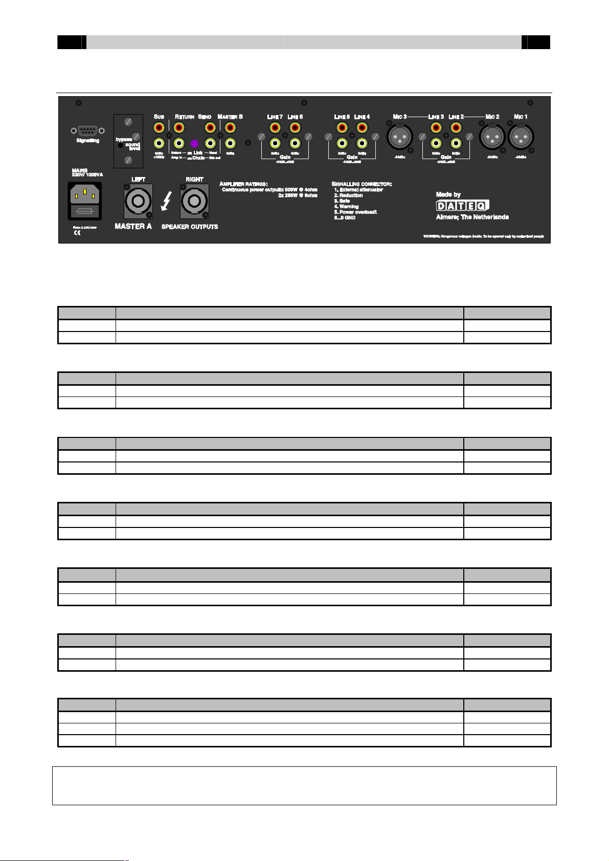
Op de achterzijde van de MAC5 zitten de aansluitingen voor de audio in,- en uitgangen. Ook
bevinden zich hier de euro-netentree (met ingebouwde netzekering).
Master A uitgangen (Neutrik speakon NL4)
Pen Functie Type
1+ Signaal + Uit
1- Signaal - GND
Master B stereo uitgangen (Cinch female)
Pen Functie Type
Tip Audio + Uit
Shield Massa A-GND
Effect send (Cinch female)
Pen Functie Type
Tip Audio + Uit
Shield Massa A-GND
Effect return (Cinch female)
Pen Functie Type
Tip Audio + In
Shield Massa A-GND
Stereo sub (woofer) uitgang (Cinch female) (<100 Hz)
Pen Functie Type
Tip Audio + Uit
Shield Massa A-GND
Line stereo Ingangen (Cinch female)
Pen Functie Type
Tip Audio + In
Shield Massa A-GND
Mic/ Mic Front/ Mic Rear symmetrische Ingangen (XLR 3-pins female)
Pen Functie Type
1 Massa A-GND
2 Audio + In
3 Audio - In
SCHAKEL DE MAC5 ALTIJD UIT VOORDAT AANSLUITINGEN WORDEN AANGEPAST!!!
OP DE LUIDSPREKERKLEMMEN KUNNEN GEVAARLIJK HOGE SPANNINGEN STAAN. TEVENS KAN DE INGEBOUWDE
VERSTERKER EEN ZEER HOGE GELUIDSDRUK PRODUCEREN!!!
Page 7
NL
Dateq MAC5 Handleiding Installeren
Aansluitingen
6
NL4 MASTER A
Luidspreker uitgangen op NL4-connectoren voor het linker en rechter kanaal
van Master A. Hierop kunnen direct luidsprekers tot minimaal 2 ohm worden
aangesloten. Zie de technische specificaties voor het maximale
uitgangsvermogen bij de verschillende belastingen.
MASTER B Ongebalanceerde uitgangen op cinch-connectoren. Deze kunnen worden
gebruikt om de MAC5 aan te sluiten op een extra versterker of recorder.
SUB Aansluiting voor een actieve subwoofer. Alleen frequenties lager dan
100Hz worden doorgegeven. De SUB-uitgang is verbonden met master A,
dus de limiter zal ook ingrijpen op de SUB-uitgang.
SEND/ RETURN Als de schakelaar in de ‘link’ stand staat kan de send uitgang worden
gebruikt als passieve master A uitgang. De return ingang staat direct
verbonden met de eindversterker.
Houd er rekening mee dat 0dBu ingangssignaal op de ‘return’ ingang
overeenkomt met het maximale vermogen uit de eindversterker!!!
Als de schakelaar in de ‘chain’ stand staat is de master A uitgang
losgekoppeld van de eindversterker ingang. Nu is het mogelijk om een extra
equalizer of een compressor aan te sluiten. De limiter meet op de eindversterker ingang, maar verzwakt op de master A uitgang. Houd hier
rekening mee wanneer alleen de eindversterker van de MAC5 wordt gebruikt!
Houd er rekening mee dat 0dBu ingangssignaal op de ‘amp in’ ingang
overeenkomt met het maximale vermogen uit de eindversterker!!!
KANAAL 4...7 Cinch-connectoren voor de stereokanalen. Elke ingang is voorzien van een
gain-trimmer aan de achterzijde. De ingangsgevoeligheid is hiermee
instelbaar tussen -14dBu en +20dBu.
KANAAL 2/ 3 Gecombineerd mono Mic/ stereo line kanaal met een elektronisch
gebalanceerde microfooningang op XLR-connector en een stereo cinch
ingang op line-niveau.
KANAAL 1 Dit kanaal heeft twee elektronisch gebalanceerde microfooningangen op
XLR-connector (Mic front en Mic rear).
MAINS/ FUSE Euro net entree. De MAC5 werkt op een netspanning van 195…250V/ 50Hz.
Type netzekering: 5x20mm (klein), 3.15A traag.
Signalling connector:
Pen nummer Functie Omschrijving
1 Verzwakker Sluit hierop een 100k lineaire potmeter aan om de maximale geluidsdruk extern te verzwakken.
2 Reduction Actief wanneer het geluid gereduceerd wordt. 12V/ 12mA max.
3 Safe Actief als de geluidsdruk meer dan 6dB onder de maximale geluidsdruk ligt. 12V/ 12mA max.
4 Warning Actief als de geluidsdruk boven de maximale geluidsdruk ligt. 12V/ 12mA max.
5 Power overload Actief wanneer de stroombegrenzing van de eindversterker actief wordt. 12V/ 12mA max.
6…9 GND
Instellingen
SOUND LEVEL Instelpunt voor de maximale geluidsdruk. Hiermee kan het maximaal te
BYPASS Druk deze schakelaar in om de ingebouwde limiter buiten werking te stellen.
EFFECT LINK Met deze schakelaar kunnen de voor en de eindversterker van elkaar
CHAIN worden losgekoppeld. In de ‘link’ stand zijn de cinch-bussen te gebruiken als
leveren vermogen van de eindversterker worden ingesteld.
effect-send en effect return aansluitingen. Door de schakelaar in de ‘chain’
stand te zetten wordt de uitgang van de mixer losgekoppeld van de ingang
van de eindversterker.
Voor alle audio cinch-connectoren geldt:
Wit = Links, Rood = Rechts.
Page 8
7
Bedienen Dateq MAC5 Handleiding
NL
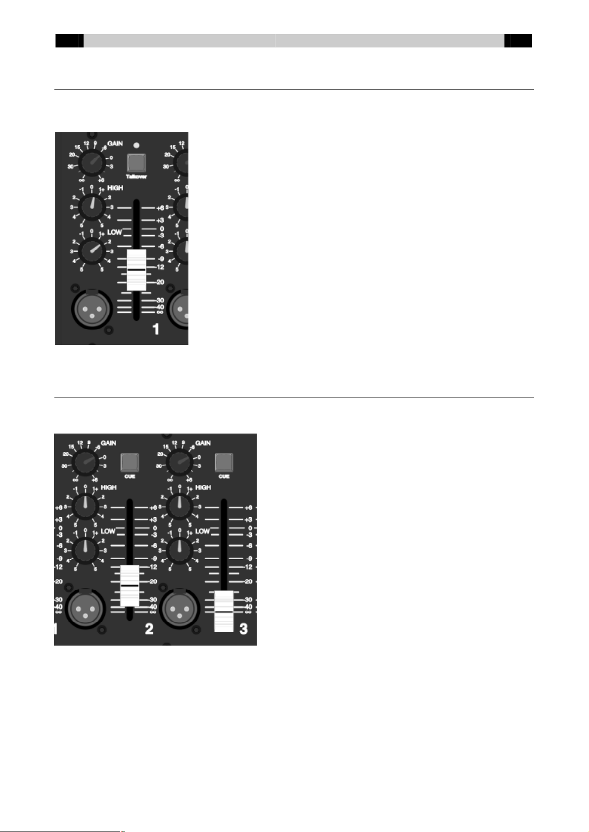
Microfoon kanaal met Talkover (1)
Op dit kanaal kan een microfoon worden aangesloten (aan de voor,- of aan de achterzijde). Het
kanaal is voorzien van volumeregeling en een 2-voudige toonregeling.
GAIN Bepaalt de voorinstelling van het volume voor
zowel
de Mic Front als de Mic Rear ingang.
TALKOVER Schakelt de TalkOver functie aan of uit. Als deze
knop is ingedrukt licht de LED groen op en de
TalkOver functie is geactiveerd. Wanneer er in de
microfoon wordt gesproken zullen de overige
kanalen verzwakt worden en zal de LED rood
oplichten om aan te geven dat de voice-over actief
is.
HIGH Hoge tonen regelaar.
LOW Lage tonen regelaar.
FADER 60mm fader waarmee het volume van dit kanaal
kan worden geregeld.
Gecombineerd microfoon-/ lijnkanaal (2/ 3)
Deze kanalen kunnen worden gebruikt om een microfoon of een lijnbron op aan te sluiten. De
kanalen zijn voorzien van volumeregeling, een 2-voudige toonregeling en voorafluistering.
GAIN Bepaalt de voorinstelling van het
volume voor zowel de mono
microfoon als de stereo line ingang.
CUE Schakelt voorafluistering aan en uit.
Als deze knop is ingedrukt is het
signaal van dit kanaal hoorbaar op
de hoofdtelefoon en zichtbaar op de
LED VU-meter. De master CUE
LEDs gaan nu uit.
HIGH Hoge tonen regelaar.
LOW Lage tonen regelaar.
FADER 60mm fader waarmee het volume
van dit kanaal kan worden geregeld.
Page 9

NL
Dateq MAC5 Handleiding Bedienen
Stereo Lijnkanalen (4 ... 7)
Gebruik deze kanalen om stereobronnen op aan te sluiten. Elk kanaal is voorzien van een
voorafluistering en een gain-trimmer op het connectorbord.
CUE Schakelt voorafluistering aan en uit. Als
deze
knop is ingedrukt is het signaal van dit
kanaal hoorbaar op de hoofdtelefoon en
zichtbaar op de LED VU-meter. De master
CUE LEDs gaan nu uit.
FADER 60mm fader waarmee het volume van dit
kanaal kan worden geregeld.
8
Mastersectie (A en B)
De MAC5 is voorzien van twee mastersecties (actieve uitgang A en passieve uitgang B).
Elke sectie bestaat uit een 2-voudige toonregeling, balansregeling, volumeregeling en
afluistering.
HIGH Hoge tonen regelaar.
LOW Lage tonen regelaar.
BAL Bepaalt de balans tussen het
linker en rechter kanaal.
MASTER A & B Volumeregelaar voor de versterker
uitgang en de ongebalanceerde
stereo uitgang.
MASTER Schakelt de hoofdtelefoon
CUE afluistering om tussen Master A en
Master B.
POWER Netspannings-schakelaar.
PHONES Volumeregelaar voor de
hoofdtelefoon. Op deze aansluiting
staat het selecteerde CUE-signaal.
Ingebouwde SPL-limiter
De limiter zorgt ervoor dat het maximale vermogen van de eindversterker kan worden begrensd.
Zodra de limiter het geluid begrenst zal de limit-LED groen oplichten. Bij een oversturing in de
eindversterker wordt de LED rood. Het geluid zal direct worden gereduceerd. Na enige tijd zal het
oude geluidsniveau worden hersteld. De rode LED zal nu knipperen. Als de LED geel oplicht
geeft dit aan dat het geluid van de versterker wordt onderdrukt. Zodra er geluid wordt
aangeboden zal de versterker automatisch terug actief worden.
Page 10

9
Technische specificaties Dateq MAC5 Handleiding
NL
Technische specificaties
MONO INPUTS
MIC (kanaal 1, 2 en 3)...................................................XLR-3 female, elektronisch gebalanceerd
Signaalniveau.....................................................-54 dB @ 600 Ohm variabel
Impedantie.........................................................2400 Ohm nominaal
Ingangsruis........................................................< -100 dB (IHF-A)
Headroom..........................................................19 dB
STEREO INPUTS
LINE (kanaal 2 en 3).....................................................Cinch
Signaalniveau.....................................................0 dB @ 600 Ohm variabel
Ingangsimpedantie.............................................10 kOhm nominaal
Ingangsruis........................................................< -70 dB (IHF-A)
Kanaalscheiding.................................................> 65 dB @ 1 kHz
LINE (kanaal 4...7)........................................................Cinch
Signaalniveau.....................................................0 dB @ 600 Ohm instelbaar niveau
Ingangsimpedantie.............................................7 kOhm nominaal
Ingangsruis........................................................< -77 dB (IHF-A)
Kanaalscheiding.................................................> 70 dB @ 1 kHz
TOONREGELING
EQUALISER KANAAL 1 EN KANAAL 2
High...................................................................10 kHz ±12 dB, Shelving
Low....................................................................30 Hz ±18 dB, Shelving
EQUALISER MASTER
High...................................................................15 kHz ±12 dB, Shelving
Low....................................................................30 Hz ±18 dB, Shelving
UITGANGEN
VERSTERKER UITGANG (NL4)...................................2x 500 Watt EIAJ @ 1kHz, 1% THD
2x 260 Watt EIAJ @ 1kHz, 1% THD
2 x 390 Watt RMS/ 4 Ohm @ 1kHz, 0.5% THD
2 x 240 Watt RMS/ 8 Ohm @ 1kHz, 0.5% THD
SLEW RATE.................................................................20 V/uS
AMPLIFIER GAIN.........................................................39x (32dB)
DAMPING FACTOR......................................................>100 @ 1-1000Hz; 8 ohm belasting
MASTER OUT B (Cinch)...............................................0 dB ongebalanceerd/ 600 Ohm/ variabel
PHONES (6,3 mm TRS Jack).......................................0,3 W @ 4 Ohm/ Impedantie 4..32 Ohm
SEND / RETURN..........................................................Link/ Chain schakeling hard/ zacht mogelijk
UITGANG LIMITER
SIGNALLING CONNECTOR.........................................1. External attenuator
2. Reduction
3. Overload
4. Warning
5. Power overload
6…9 GND
FREQUENTIEKARAKTERISTIEK
MIC NAAR MASTER.....................................................25 Hz...25 kHz -1 dB
OVERIG NAAR MASTER..............................................10 Hz...25 kHz -1 dB
THD + N.......................................................................0,01% nominaal (CCIR-RMS)
ALGEMEEN
VERMOGEN
Spanningsbereik.................................................195...250 VAC / 50 Hz
Opgenomen Vermogen......................................1000 Watt (maximaal)
AFMETINGEN EN GEWICHT
Front..................................................................483 x 132 mm (B x H) = 19”, 3HE
Cutout................................................................445 x 132 mm (B x H)
Kastdiepte (inbouw)............................................210 mm zonder connectoren
Gewicht..............................................................6.5 kg Netto
Dateq Audio Technologies BV houdt zich het recht voor om specificaties te wijzigen zonder voorafgaande melding.
Page 11

Page 12

Page 13

EN
Dateq MAC5 Manual Safety instructions
2
Safety instructions
1 All safety instructions, warnings and operating instructions must be read first.
2 All warnings on the equipment must be heeded.
3 The operating instructions must be followed.
4 Keep the operating instructions for future reference.
5 The equipment may never be used in the immediate vicinity of water; make sure that water
and damp cannot get into the equipment.
6 The equipment may only be installed or fitted in accordance with the manufacturers
recommendations.
7 The equipment must be installed or fitted such that good ventilation is not obstructed in any
way.
8 The equipment may never be installed in the immediate vicinity of sources of heat, such as
parts of heating units, boilers, and other equipment that generates heat (including
amplifiers).
9 Connect the equipment to a power supply of the correct voltage, using only the cables
recommended by the manufacturer, as specified in the operating instructions and/or shown
on the connection side of the equipment.
10 The equipment may only be connected to a legally approved earthed mains power supply.
11 The power cable or power cord must be positioned such that it cannot be walked on in
normal use, and objects that might damage the cable or cord cannot be placed on it or
against it. Special attention must be paid to the point at which the cable is attached to the
equipment and where the cable is connected to the power supply.
12 Ensure that foreign objects and liquids cannot get into the equipment.
13 The equipment must be cleaned using the method recommended by the manufacturer.
14 If the equipment is not being used for a prolonged period, the power cable or power cord
should be disconnected from the power supply.
15 In all cases where there is a risk, following an incident, that the equipment could be unsafe,
such as:
· if the power cable or power cord has been damaged
· if foreign objects or liquids (including water) have entered the equipment
· if the equipment has suffered a fall or the casing has been damaged
· if a change in the performance of the equipment is noticed
Appropriately qualified technical staff must check it.
16 The user may not carry out any work on the equipment other than that specified in the
operating instructions.
Page 14

3
Introduction Dateq MAC5 Manual
EN
Dateq MAC5
The MAC5 is a seven-channel 19-inch powered mixer. It will perform at it’s best in pub’s, danceschools etc. The MAC5 is equipped with three microphone inputs. Two of these inputs can be
switched to line-sensitivity. Four line inputs are available.
Channel 1 has a voice-activated talk-over circuit. This circuit automatically attenuates the other
channels when audio is present on the first microphone channel. The function can be switched on
and off at the front.
The MAC5 has two outputs: an active (amplified) master A, and a passive master B. Both masters
have a two-way equaliser, a balance adjustment and a volume-control.
Master A amplifier has speakon NL4 connectors. Master B output has unbalanced cinchconnectors.
Product support
For questions about the MAC5, accessories and other products, please contact:
Dateq Audio Technologies B.V.
De Paal 37 Phone: +31 36 54 72 222
1351 JG Almere Fax: +31 36 53 17 776
The Netherlands E-mail: info@dateq.nl
Internet: www.dateq.nl
Page 15

EN
445 mm
Dateq MAC5 Manual Installing
Installing the MAC5
The MAC5 is designed to fit in a 19-inch rack. It is 3 units high (132mm). The cabinet will fit in an
opening of 445 x 132 x 210mm (W x H x D). See the drawings below.
The 19-inch mounting bracket is 2mm thick. When installing the mixer, remember to allow
sufficient room for the connectors and plugs on the MAC5’s rear!
Do not cover the ventilation-holes at the left and right side of the unit. The MAC5 has an
automatic fan. When the amplifier becomes hot the fan will switch on.
CUT
132 mm
OUT
4
210 mm
Page 16

5
Operation Dateq MAC5 Manual
MAC5 Connector board
EN
At the rear all the audio in,- and outputs can be found, just as the mains-connector with a built-in
fuse.
Master A outputs (Neutrik speakon NL4)
Pin Function Type
1+ Signal + Out
1- Signal - GND
Master B stereo outputs (Cinch female)
Pin Function Type
Tip Audio + Out
Shield GND A-GND
Effect send (Cinch female)
Pin Function Type
Tip Audio + Out
Shield GND A-GND
Effect return (Cinch female)
Pin Function Type
Tip Audio + In
Shield GND A-GND
Stereo sub (woofer) output (Cinch female) (<100 Hz)
Pin Function Type
Tip Audio + Out
Shield GND A-GND
Line stereo inputs (Cinch female)
Pin Function Type
Tip Audio + In
Shield GND A-GND
Mic/ Mic Front/ Mic Rear balanced inputs (XLR 3-pins female)
Pin Function Type
1 GND A-GND
2 Audio + In
3 Audio - In
BEFORE CHANGING ANY CONNECTIONS, ALWAYS SWITCH OFF THE MAC5!!!
THE BUILT-IN AMPLIFIER IS CAPABLE OF PRODUCING DANGEROUSLY HIGH VOLTAGES AT THE SPEAKER OUTPUTS AND
VERY HIGH AUDIO-LEVELS!!!
Page 17

EN
Dateq MAC5 Manual Installing
Connections
6
NL4 MASTER A
Loudspeaker outputs on NL4-connectors for the left and right master A
outputs. Speakers with a minimum impedance of 2 ohms can be
connected directly. See the technical specifications for the maximum
output power at the different amplifier loads.
MASTER B Unbalanced master B outputs at cinch-connectors. They can be used to
connect the MAC5 to a recorder or extra amplifier.
SUB An active subwoofer can be connected here. Only low frequencies
(<100Hz) will be passed thru. The SUB-output is connected to master A,
so the limiter also affects the SUB-output.
SEND/ RETURN When the switch is set to ‘link’ the send output can be used as a passive
master A output. The return input is directly inserted into the amplifier.
Remember that a 0dBu input signal at the ‘return’ input will result in
the maximum amplifier output signal!!!
With the switch set to ‘chain’ the master A output is disconnected from the
amplifier input, and they can be used separately. An additional equaliser,
a compressor or other device can be inserted between the mixer and the
amplifier. The limiter measures at the amplifiers input, however the master
A output level is attenuated! Keep this in mind when the MAC5 is used as
amplifier only!
Remember that a 0dBu input signal at the ‘amp in’ input will result in
the maximum amplifier output signal!!!
CHANNEL 4...7 Cinch-connectors for the stereo-inputs. Each input is equipped with a gain-
trimmer at the rear. The sensitivity can be adjusted from -14dBu…+20dBu.
CHANNEL 2/ 3 Combined mono Mic/ stereo line channel with electronically balanced
microphone input at XLR connector and a stereo cinch connector.
CHANNEL 1 This channel has two electronically balanced microphone inputs at XLT
connectors (Mic front en Mic rear).
MAINS/ FUSE Mains input. The MAC5 operates 195…250V/ 50Hz. Fuse: 5x20mm
(small), 3.15A slow.
Signalling connector:
Pin number Function Description
1 Attenuator Connect a 100kOhm potmeter to adjust the maximum soundlevel externally.
2 Reduction Active when the sound-level is attenuated. 12V/ 12mA max.
3 Safe Active when the sound-level is more than 6dB below the maximum sound-level. 12V/ 12mA max.
4 Warning Active when the sound-level is above the maximum sound-level. 12V/ 12mA max.
5 Power overload Active when the amplifiers current-protection is activated. 12V/ 12mA max.
6…9 GND
Settings
SOUND LEVEL used to adjust the maximum soundlevel. The amplifiers power output can
BYPASS Push this button to disable the built-in limiter.
EFFECT LINK This switch is used to connect the mixer output to the amplifiers input.
CHAIN When ‘linked’ the cinch-connectors can be used as an effect-send and
be attenuated with this potmeter.
return function. By switching to ‘chain’ the mixer output and amplifier input
are separated.
For all cinch-connectors:
White = Left, Red = Right.
Page 18

7
Operation Dateq MAC5 Manual
EN
Microphone input with Talkover (1)
A microphone can be connected to this input at the front or the rear-connector. This channel has
a two-way equaliser and a gain-control.
GAIN Adjusts the volume-setting for the front and rear
microphone input.
TALKOVER Enables or disabled the TalkOver function. When
the button is pushed the LED will light up green;
indicating that the function is switched on. When
talking in the microphone the LED will light up RED
and all the other channels are attenuated.
HIGH High-tone control.
LOW Low-tone control.
FADER 60mm fader to adjust the channels volume.
Combined microphone/ line channel (2/ 3)
These channel can be used to connect a microphone or a line-level source. The channels have a
two-way tone control, a volume-control and a pre-fader listening function (CUE).
GAIN Adjusts the volume-setting for both
the microphone and the line input.
CUE Enables the pre-fader listen function.
The audio of this channel can be
monitored on the headphones and
the VU-meters. The master-CUE
LEDs will switch off when this button
is pushed.
HIGH High-tone control.
LOW Low-tone control.
FADER 60mm fader to adjust the channels
volume.
Page 19

EN
Dateq MAC5 Manual Operation
Stereo line inputs (4 ... 7)
These channels can be used to connect line-level sources to the MAC5. Each channel has a
CUE-function and a gain-trimmer at the connector board.
CUE Enables the pre-fader listen function.
The audio of this channel can be
monitored on the headphones and
the VU-meters. The master-CUE
LEDs will switch off when this button
is pushed.
FADER 60mm fader to adjust the channels
volume.
8
Master section (A and B)
The MAC5 has two master sections: an active master A output and a passive master B output.
Each master-unit has a two-way tone control, a balance function, volume-control and a CUEfunction.
HIGH High-tone control.
LOW Low-tone control.
BAL Adjusts the balance between the left
and the right channel.
MASTER A & B Volume-control for the master A and
master B outputs.
MASTER Switches the headphones signal
CUE between master A and master B.
POWER On/ Off switch.
PHONES Volume-control for the headphones.
The selected CUE-signal can be
monitored here.
Built-in SPL-limiter
The limiter continuously measures the output power and automatically lowers it if necessary.
When the limiter is active (reducing the signal) the limit-LED will light up green. When the
amplifier is overloaded (over-current) the LED will light up red. The audio level will be reduced
immediately. After some time the LED starts blinking red and the audio-level will return to it’s
previous level. If the LED illuminates yellow the amplifier is muted. The amplifier will automatically
un-muted when audio is detected.
Page 20

9
Technical specifications Dateq MAC5 Manual
EN
Technical specifications
MONO INPUTS
MIC (channel 1, 2 and 3)...............................................XLR-3 female, electronically balanced
Signal level.........................................................-54 dB @ 600 Ohm variable
Impedance.........................................................2400 Ohm nominal
Input noise.........................................................< -100 dB (IHF-A)
Headroom..........................................................19 dB
STEREO INPUTS
LINE (channel 2 and 3).................................................Cinch
Signal level.........................................................0 dB @ 600 Ohm variable
Impedance.........................................................10 kOhm nominal
Input noise.........................................................< -70 dB (IHF-A)
Channel separation............................................> 65 dB @ 1 kHz
LINE (channel 4...7)......................................................Cinch
Signal level.........................................................0 dB @ 600 Ohm adjustable
Impedance.........................................................7 kOhm nominal
Input noise.........................................................< -77 dB (IHF-A)
Channel separation............................................> 70 dB @ 1 kHz
TONE CONTROL
EQUALISER CHANNEL 1 AND CHANNEL 2
High...................................................................10 kHz ±12 dB, Shelving
Low....................................................................30 Hz ±18 dB, Shelving
EQUALISER MASTER
High...................................................................15 kHz ±12 dB, Shelving
Low....................................................................30 Hz ±18 dB, Shelving
OUTPUTS
AMPLIFIER OUTPUT (NL4)..........................................2x 500 Watt EIAJ @ 1kHz, 1% THD
2x 260 Watt EIAJ @ 1kHz, 1% THD
2 x 390 Watt RMS/ 4 Ohm @ 1kHz, 0.5% THD
2 x 240 Watt RMS/ 8 Ohm @ 1kHz, 0.5% THD
SLEW RATE.................................................................20 V/uS
AMPLIFIER GAIN.........................................................39x (32dB)
DAMPING FACTOR......................................................>100 @ 1-1000Hz; 8 ohm load
MASTER OUT B (Cinch)...............................................0 dB unbalanced/ 600 Ohm/ variable
PHONES (6,3 mm TRS Jack).......................................0,3 W @ 4 Ohm/ Impedance 4..32 Ohm
SEND / RETURN..........................................................Link/ Chain switchable hard/ soft
OUTPUTS LIMITER
SIGNALLING CONNECTOR.........................................1. External attenuator
2. Reduction
3. Overload
4. Warning
5. Power overload
6…9 GND
FREQUENCE RESPONSE
MIC TO MASTER..........................................................25 Hz...25 kHz -1 dB
REST TO MASTER.......................................................10 Hz...25 kHz -1 dB
THD + N.......................................................................0,01% nominal (CCIR-RMS)
GENERAL
POWERSUPPLY
Voltage range.....................................................195...250 VAC / 50 Hz
Power consumption............................................1000 Watt (max.)
DIMENSIONS AND WEIGHT
Front..................................................................483 x 132 mm (B x H) = 19”, 3HE
Cut-out...............................................................445 x 132 mm (B x H)
Cabinet depth.....................................................210 mm without connectors
Weight...............................................................6.5 kg Nett.
Dateq Audio Technologies B.V. reserves the right to amend specifications without notice.
Page 21

Page 22

DECLARATION OF CONFORMITY
acc.to art.10.1 EMC directive 89/336/EEC
We, DATEQ Audio Technologies B.V.
de Paal 37
1351 JG ALMERE
THE NETHERLANDS
hereby declare, exclusively to our responsibility, that this product
Type: MAC 5 Serialnrs.: 48-XXXX
to which this declaration applies, is in accordance with the following
harmonized European norms
EN 50081-1 and EN 50082-1
According to the regulations of the EMC-directive 89/336/EEG, amended by
directive 91/263/EEG, 92/31/EEG and 93/68/EEG.
EN 60065
According to the regulations of IEC 65: 1985 + A1: 1987 + A2: 1989 + A3:
1992, mod. Ratification: 1993-07-06
Almere, October 9th 2003 Managing director
stamp: signature:
Page 23

model / Geräte Typ / produit:
serienr / serial # / Seriennr. / no. de série:
inzenden naar DATEQ bewaren met de aankoop-/kassa-bon
GARANTIE / GUARANTEE GARANTIE / GUARANTEE
mail this to DATEQ keep this with original invoice/cash
einschicken nach DATEQ behalten mit der Originalrechnung
envoyer à DATEQ conserver avec la facture originale
model / Geräte Typ / produit:
serienummer / serial # / Seriennummer / no. de série:
handtekening / signature / Unterschrift
dealer / dealer / Vertragshändler / concessionnaire:
adres / adress / Adresse / adresse:
woonplaats / city / Wohnort / place:
postcode / zip code / PLZ:
koper / buyer / Käufer / acheteur:
adres / adress / Adresse / adresse:
woonplaats / city / Wohnort / place:
postcode / zip code / PLZ:
land / country / Land / pays:
- -- -
aankoopdatum / purchase date / Kaufdatum / date d'achat: aankoopdatum / purchase date / Kaufdatum / date d'achat:
m m
d d
Page 24

where the product is used, repairs done by non-authorised service stations,
accidents, actsof God,or any causebeyond thecontrol ofDATEQ, including butnot
limited tolightning, water,fire, publicdisturbances and improperventilation.
d'accidents de cas de force majeure ou de toute autre cause hors du contrôle de
DATEQ, en particulier mas non de façon exclusieve à la foudre, l'inondation,
l'incendie, lestroubles publics,des piles quiont coulé,une mauvaise ventilation.
maintenance of this product and the installation or the use of this product in a
manner inconsistent with the technical or safety standards in force in the country
contradiction avecles standards techniquesou de sécurité envigueur dans lepays
où le produit est utilisé, reparations faites par les réparateurs non agréés;
purposes or in accordance with DATEQ's instructions on the proper use and
la négligence ou faute l'utilisateur, et l'installation ou l'utilisation de ce produit en
theguarantee of this product, (c) damageto this product resulting from abuse and
misuse, including but not limited to the failure to use this product for its normal
à la mise en oeuvre dela garantie de ce produit; (c)l'endommagement dui produit
résultant d'abuset demauvais usage, enparticulier maisnon de façonexclusieve à
repair or replacements of parts due to normal wear and tear, (b) home service
transport costsand other costsand risks oftransport relating directlyor indirectly to
les contrôles périodiquies, l'entretien, la réparation et le remplacement de pièces
par suited'usure normale;(b) les fraiset lesrisques de transportdirects ouindirects
original invoice/cashticket issued tothe consumer by theretailer. DATEQ reserves
the right to refuse guarantee service if this information or the products serial
number hasbeen removed orchanged after theoriginal purchase ofthe product. 2.
This guarantee covers none of the following: (a) periodic check-ups, maintenance,
remises au consommateur parle distributeur sont présentées. DATEQ se réserve
le droit de refuser sa garantie si tout ou partie de ces mentions ou le numero de
série de l'appareil a été ou modifié après l'acquisition originale du produit par le
client chezle distribiteur. 2. Cettegarantie ne couvreaucun des pointssuivants: (a)
defective parts on the condetions explained hereafter. 1. The guarantee will be
granted only ifthe correctly filled outguarantee card is presented togetherwith the
charge le produitou à défaut DATEQsous les conditions exposées ci-après. 1. La
garantie sera seulement assurée si la facture origiale et la carte de garantie
GARANTIE BEPALINGEN: DATEQ garandeert dat dit produkt vrij isvan defecten
in materialen en/of contructie gedurende 12 maanden na aankoop. Indien
gedurende deze periode het produkt defecten vertoont tengevolge van
ondeugdelijke materialen en/of constructie zal DATEQ zonder berekening van
kosten voor arbeidsloon of onderdelen het produkt repareren volgens de
voorwaarden zoals hierna uiteen zijn gezet. 1. Garantie wordtverleend uitsluitend
op vertoon van de garantiekaart tezamen met de originele, door de dealer
afgegeven factuur/kassabon. DATEQ behoudt zich het recht voor garantie af te
wijzen indien de hierboven genoemde gegevens of het serienummer van het
produkt zijn verwijderd of veranderd na de oorspronkelijke aankoop. 2. Deze
garantie dekt niet: (a) periodiekecontroles, onderhoud en reparatie of vervanging
van onderdelen door normale slijtage, (b) kosten en risico van transport alsmede
voorrijkosten, direct ofindirect verband houdende met degarantie van dit produkt,
(c) schade aan dit product ten gevolge van mistbruik of verkeerd gebruik met
inbegrip vanmaar niet beperkttot abnormaal gebruikniet in overeenstemming met
de DATEQ instructies over juist gebruik en onderhoud van het produkt en het
installeren of gebruiken van dit produkt in tegenstrijd met de technische of
veiligheidsnormen zoals die van kricht zijn in het land waar het produkt wordt
gebruikt, reparaties uitgevoerd door niet erkende service stations, ongevallen
force majeur,of welke oorzaak dan ook buiten demacht van DATEQ,met inbegrip
van maar niet beperkt tot bliksem, water, vuur, publieke oproer en ondeugdelijke
ventilatie.
GARANTEE CONDITIONS: DATEQ guarantees this product to be free of defects
in materialsand workmanship atthe timeof its originalpurchase for theperiod of 12
months. If during this period of guarantee the product proves defective due to
improper materials or workmanship, DATEQ will repair or this product or its
CONDITIONS DE GARANTIE:DATEQ garantit que ce produit est exempt de
défaut dematière etde fabrication existantlors del'acquisition originale parle client
pour un délai d'un an. Si ce produit s'avère défectueux pendant la période de
garantie en raison de matière ou de fabrication incorrecte, DATEQ prendra en
Reparaturen duch nicht autorisierte Werkstätten; Unfälle, höhere Gewalt oder andere
von DATEQ nicht zu verantwordende Ursachen, insbesondere Blitzschlag, Wasser,
Feuer,Störungen der öffentlichenOrdnung undunzureichende Belüftung.
Gerätes in einer den in dem Land, in dem das Gerät bebraucht wird, geltenden
technischen oder sicherheitstechnischen Anforderungen nichtentsprechenden Weise;
Gerätes für andere als seinennormalen Zweck bzw. unter Nichtbeachtung der DATEQ
Bedienungs- und Wartungsanleitungen, und den Anschluß oder Gebrauch dieses
Gerätegarantie zusammenhängen; (c) Schäden an diesem Gerät, die verursacht
worden sind durch: Mißbrach und Fehlgebrauch, insbesondere Gebrauch dieses
Transport-, Fahrtkosten und -risiken, die unmittelbar oder mittelbar mit dieser
bzw. Reparatur oder Austausch von Teilen bedingt duch normalen Verschleiß; (b)
Garantie deckt keinen der folgenden Punkte: (a) regelmäßige Inspektionen, Wartung
Angaben oder das Seriennummer entfernt oder geändert worden sind. 2. Diese
wenn nachdem Ersterwerb desGerätes durch denVerbraucher oderden Händler diese
Garantieleistungen werden nur erbracht, wenn die Garantiekarte zusammen mit der
Originalrechnung bzw.dem Kassenbeleg, dieder Händler dem Verbraucher ausgestellt
hat, vorgelegt wird. DATEQ behält sich das Rechtvor, Garantieleistungen abzulehnen,
aufweist. Die Garantiezeit beträgt 12 Monate. Sollten sich während der Garantiezeit
Mängel des Gerätes herausstellen, die auf Material- oder Verarbeitungsfehlern
beruhen, wird gemäß dennachstehenden Bedingungen DATEQ ohne Berechnungder
Arbeits- und Materialkosten das Gerät oder seine schadhaften Teile reparieren. 1.
GARANTIE BEDINGUNGEN: DATEQ gewährleistet für die Garantiezeit daß dieses
Gerät ab dem Zeitpunkt des Ersterwerbs keine Material und Verarbeitungsfehler
1351 JG ALMERE
The Netherlands / Niederlande / Pays Bas
De paal 37
DATEQ B.V.
briefmarke
stamp
postzegel
timbre
 Loading...