

DATEL DTL3A Datasheet
E
NEW
®
INNOVATION and EX C ELL E N C
®
DTL Series
DTL3A Model
Digitally Programmable, 2A/200V
100 Watt, Electronic Loads
Features
■
12-bit, optically isolated (500Vdc),
CMOS/TTL-compatible serial input
■
0-2 Amp output in 500µA increments
■
Output voltage to 200 Volts
■
Output power to 100 Watts
■
10MΩ minimum output impedance
■
±500µA offset error; ±0.1% gain error
■
100µsec full-scale step response
■
Update rates to 20kHz
■
Operate in parallel for higher power
■
Miniature, 2" x 2" metal package
Applications
■
Static/dynamic power-supply burn-in
■
Power-supply test and characterization
■
Battery capacity testing
■
Current-source testing
■
Capacitor discharge testing
■
Real-time load simulation
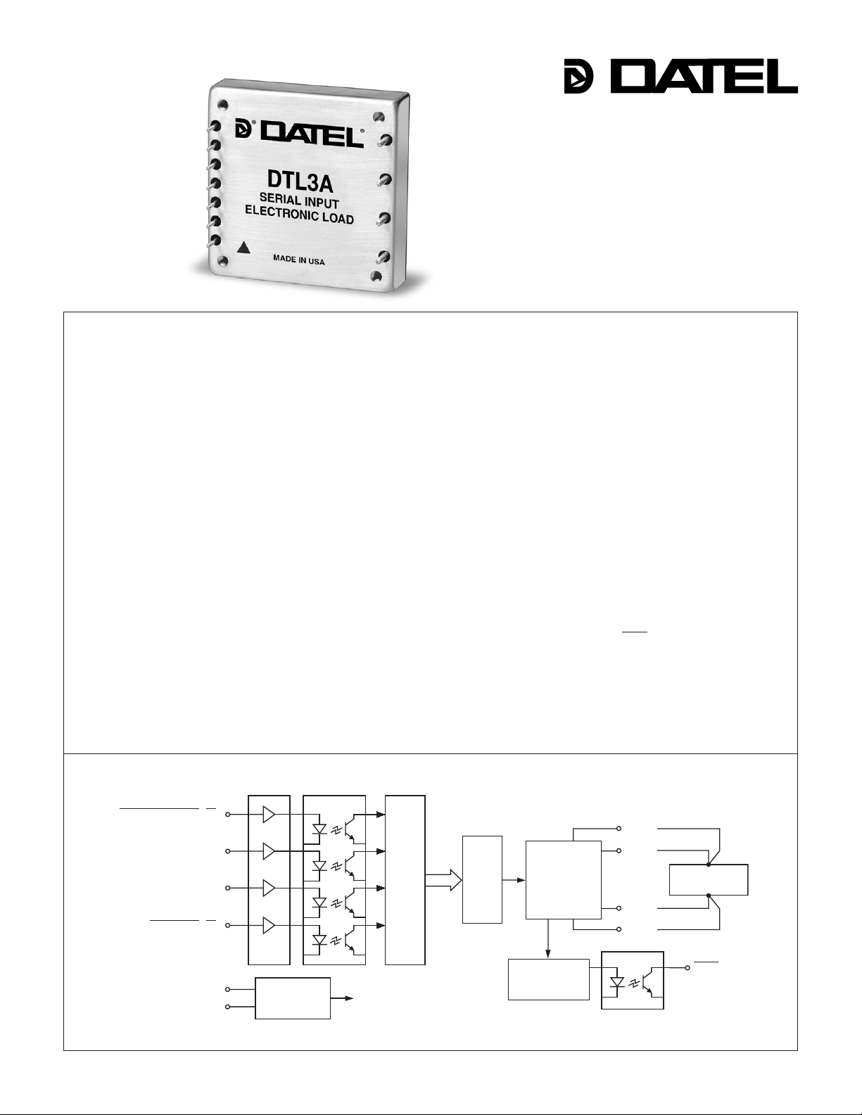
DATEL’s new DTL3A is a digitally controlled, optically isolated, serial-input elec-
tronic load that offers high compliance voltage and unprecedented control over lowlevel currents. The DTL3A is essentially a computer controlled current source that
sinks currents from 0 to 2 Amps, at loading voltages from 2.5 to 200 Volts, up to a
maximum power of 100 Watts. The DTL3A accepts a serialized, 12-bit, CMOS/TTL
digital input word, optically isolates (500Vdc) the data, latches it, and presents it to an
on-board, 12-bit, digital-to-analog (D/A) converter. The D/A output drives a near-ideal
(10MΩ output impedance), voltage-controlled current source.
One LSB (least signifi cant bit) of the D/A corresponds to a mere 500µA (0.025% of
2A) of load current. Combined with the DTL3A’s ±500µA max. offset error and ±0.1%
max. gain error, this precise digital control gives users extraordinary command over
the generation of low-level load currents. A 100mA current, for example, is guaranteed
to have ±1mA accuracy over all specifi ed load-voltage conditions.
The DTL3A has impressive speed performance. Digital update rates to 20kHz
are possible, and settling time for a full 2A step is 100µsec. The unit is housed in a
thermally effi cient, 2" x 2" x 0.5" metal package that has an aluminum baseplate with
through-hole spacers for easy pcb mounting and/or external heat-sink attachment.
The DTL-3A has an output compliance-voltage requirement 2.5 to 200V. Should
the output/load voltage drop below the 2.5V minimum required for proper biasing,
an internal monitoring circuit activates the DTL3A's output Fault line. See DATEL’s
DTL2A-LC for compliance voltages as low as 0.6V.
DATEL’s electronic loads, controller boards and companion software are outstand-
ing building-block components for power-supply (AC/DC and DC/DC) and powercomponent (diodes, FET’s, etc.) burn-in and test systems. They are an extremely
reliable, cost-effective solution that enables you to quickly confi gure fl exible, impres-
sively accurate systems.
INPUT
BUFFERS
CONTROL STROBE (CS)
CLOCK (CLK)
SERIAL DATA INPUT (SDI)
LATCH DATA (LD)
+5V SUPPLY
GROUND
DATEL, Inc., Mansfi eld, MA 02048 (USA) · Tel: (508)339-3000, (800)233-2765 Fax: (508)339-6356 · Email: sales@datel.com · Internet: www.datel.com
ISOLATED
DC/DC
CONVERTER
OPTO
ISOLATORS
DATA
LATCH
Figure 1. Simplifi ed Schematic
12-BIT
D/A
AMPLIFIER
AND
CURRENT
SENSOR
UNDERVOLTAGE
DETECTION
+LOAD
+LOAD
–LOAD
–LOAD
POWER DEVICE
UNDER TEST
FAULT
DTL Series
0
100 WATT, HIGH-VOLTAGE ELECTRONIC LOADS
Performance Specifi cations and Ordering Guide
➀
Input Output
Compliance
Resolution Logic Current Resolution Voltage Power Package
Model (Bits) Compatibility (Amps) (mA)
➁ (Volts) ➂ (Watts) (Case, Pinout)
DTL3A 12 CMOS/TTL ➃ 0-2 0.5 2.5-200 0-100 C24, P31
➀ Typical at TA = +25°C with nominal +5V supply voltage unless noted.
➁ The smallest increment/decrement in output current is defi ned by one LSB (least signifi cant bit) of the 12-bit
digital input word. One LSB is equal to full scale (FS) divided by 4096 which corresponds to 0.0244% of 2A or 488µA.
➂ For proper operation, the unit's output/load voltage must remain within this range. Voltages greater than the listed
maximum can damage the device. Voltages less than the minimum provide insuffi cient bias for the output stage
and will result in unpredictable or no operation. See Output Compliance Voltage and the Fault Line for details.
➃ See Performance/Functional Specifi cations for details.
PART NUMBER STRUCTURE
DTL 3
DATEL
Electronic Load
A
A-Series
High Reliability
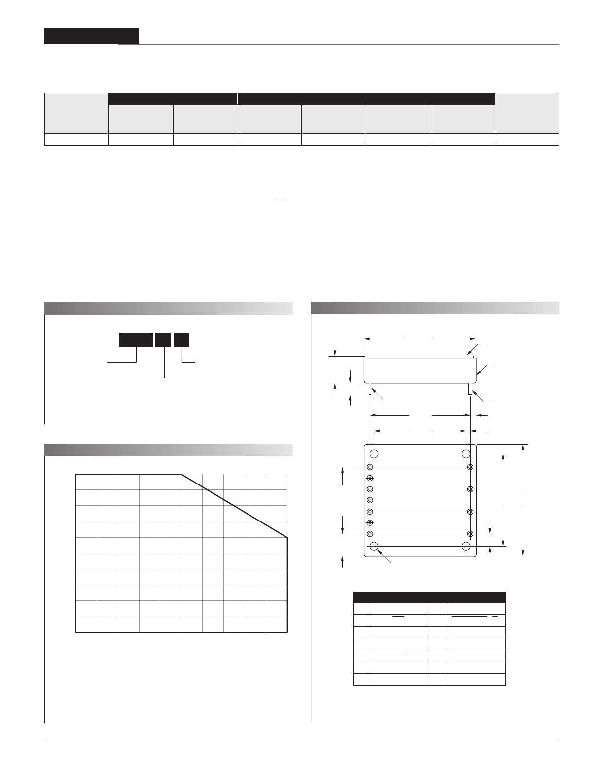
MECHANICAL SPECIFICATIONS
2.00
(50.80)
0.50
(12.70)
Case C24
ALUMINUM BASEPLATE
METAL CASE
Voltage Range:
3 = 2.5 to 200V
0.20 MIN
(5.08)
0.040 ±0.002 DIA.
(1.016 ±0.051)
1.800
(45.72)
1.640
(41.66)
0.060 ±0.002 DIA.
(1.524 ±0.051)
0.10
(2.54)
0.08
(2.03)
TEMPERATURE DERATIN
10
11
BOTTOM VIEW
8
9
2.00
1.640
(50.80)
(41.66)
0.22
(5.59)
100
90
80
70
60
50
40
Output Power/Load (Watts)
30
20
10
010 203040506070809010
Baseplate Temperature (°C)
The horizontal axis of the above chart references the temperature of the DTL3A’s alumi-
num baseplate. The device can continually dissipate up to 100 Watts if the baseplate
7
6
1.20
(30.48)
6 EQ. SP. @
0.200 (5.08)
0.40
(10.16)
5
4
3
2
1
#4-40 CLEAR THRU
(TYP. 4 PL)
I/O Connections
Pin Function P31 Pin Function P31
1 Fault 7 Control Strobe (CS)
2 Ground 8 –Load
3 +5 Volt Supply 9 –Load
4 Latch Data (LD) 10 +Load
5 Serial Data In (SDI) 11 +Load
6 Clock (CLK)
is maintained at or below +50°C. At +25°C ambient temperature, with no heat sink or
supplemental air fl ow, the DTL3A can reliably dissipate a continuous 10 Watts.
Contact DATEL for Heat Sink information.
2
 Loading...