

Datasheet BWR-5-500-D48, BWR-5-500-D24, BWR-15-165-D48, BWR-15-165-D24, BWR-12-210-D48 Datasheet (DATEL)
...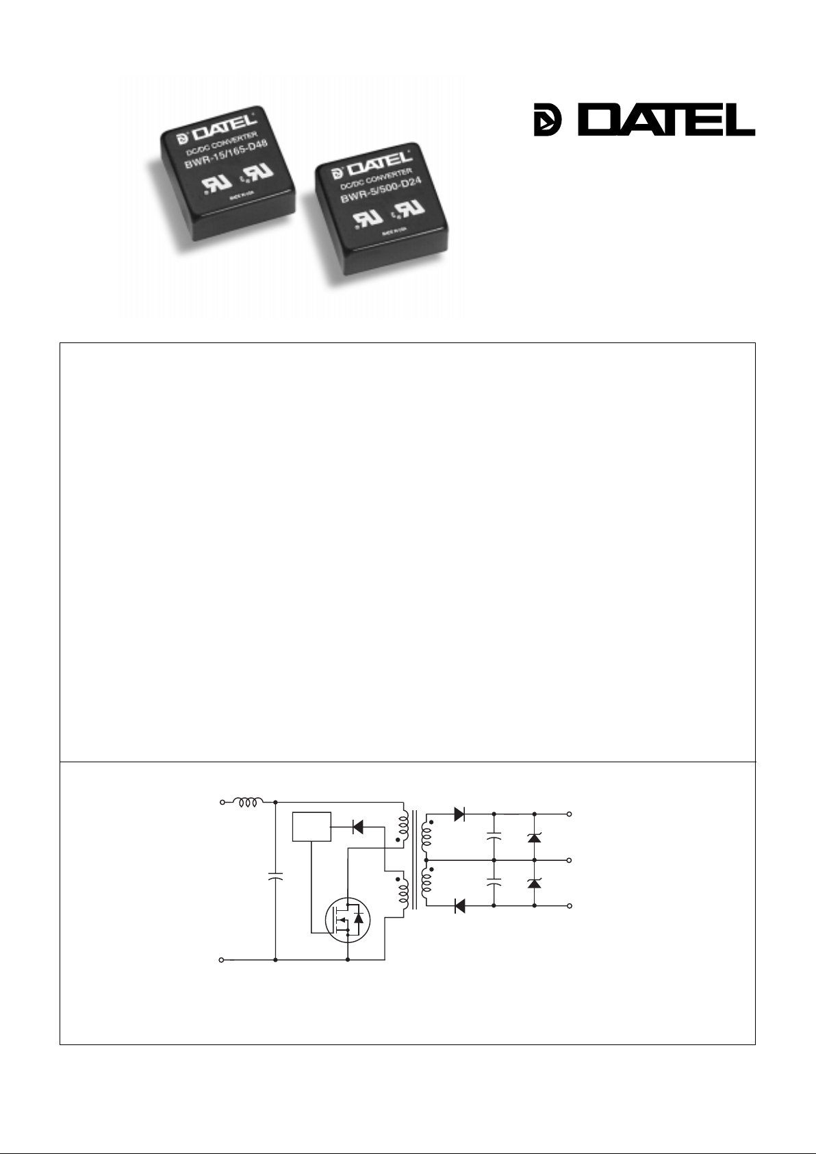
Figure 1. Simplified Schematic
* "D24" models only
Dual Output
BWR Models
Miniature, 1" x 1"
5 Watt, DC/DC Converters
Features
The migration to distributed power is accelerating. The critical need for accurate
voltages, tight regulation and rapid transient response is propelling the move to power
processing at the "point-of-use" with low-power DC/DC converters physically located
right at their loads.
DA TEL’s miniature, full f eatured, 5 W att BWR Models were specifically designed for
today’s demanding distributed po wer architectures in aerospace, marine, telecom and
computer applications. The con verters’ small size (1" x 1" x 0.45"),
full 5 Watt output capability and low cost give system architects unprecedented design
and layout flexibility.
Occupying less than 0.5in
3
total volume, these extremely compact, fully regulated
and isolated (1000Vdc) modules are available with ±5, ±12 or ±15 V olt outputs. Input
voltage ranges are either 18-36 V olts ("D24" models) or 36-72 Volts ("D48" models).
Although their overall size is 50-75% smaller than many similarly rated power
modules, these 1" x 1" BWR Models are exact, drop-in, pin-for-pin replacements for
many standard 2" x 1" and 2" x 2", 5 W att modules. They achiev e their small size and
low cost by exploiting a novel feedback approach that does not depend upon traditional
optocoupler techniques.
All models are 5-side shielded and have a non-conductive baseplate that permits
pc-card runs to be placed beneath the package. Units are assembled using highspeed automated SMT techniques and are fully encapsulated with thermally conductive
potting compound. Every unit is electrically tested before
and after encapsulation, 100% burned-in under full load, hi-pot tested, and finalelectrical tested prior to shipment. Every unit meets DA TEL’s traditional high standards
for quality and long-term reliability .
–V
OUT
+V
OUT
COMMON
+
V
IN
–
V
IN
PWM
*
DATEL, Inc., 11 Cabot Boulevard, Mansfield, MA 02048 (U.S.A.) • Tel: (508)339-3000, (800)233-2765 Fax: (508)339-6356 • Email: datellit@mcimail.com
INNOVATION and EX C ELL E N C E
®
®
■
■■
■■
■
■■
■■
■
■■
■■
■
■■
■■
■
■■
■■
■
■■
■■
■
■■
■■
■
■■
■■
■
■■
■■
■
■■
■■
■
■■
■■
■
■■
■■
■
Small size, 1" x 1" x 0.45"
Full 5 Watts output power
No external components required
Drop-in replacements for many
standard, 2" x 1" DC/DC’s
Wide input voltage ranges:
18-36V or 36-72V
Standard output voltages:
±5, ±12, ±15 Volts
Guaranteed efficiencies to 80%
Fully regulated and isolated
(1000Vdc guaranteed)
Output overvoltage protection and
current limiting
–25 to +95
o
C operating temperature
Shielded cases (5 sides)
UL1950, CSA 22.2 No. 234, and IEC950
Modifications and customs for OEM's
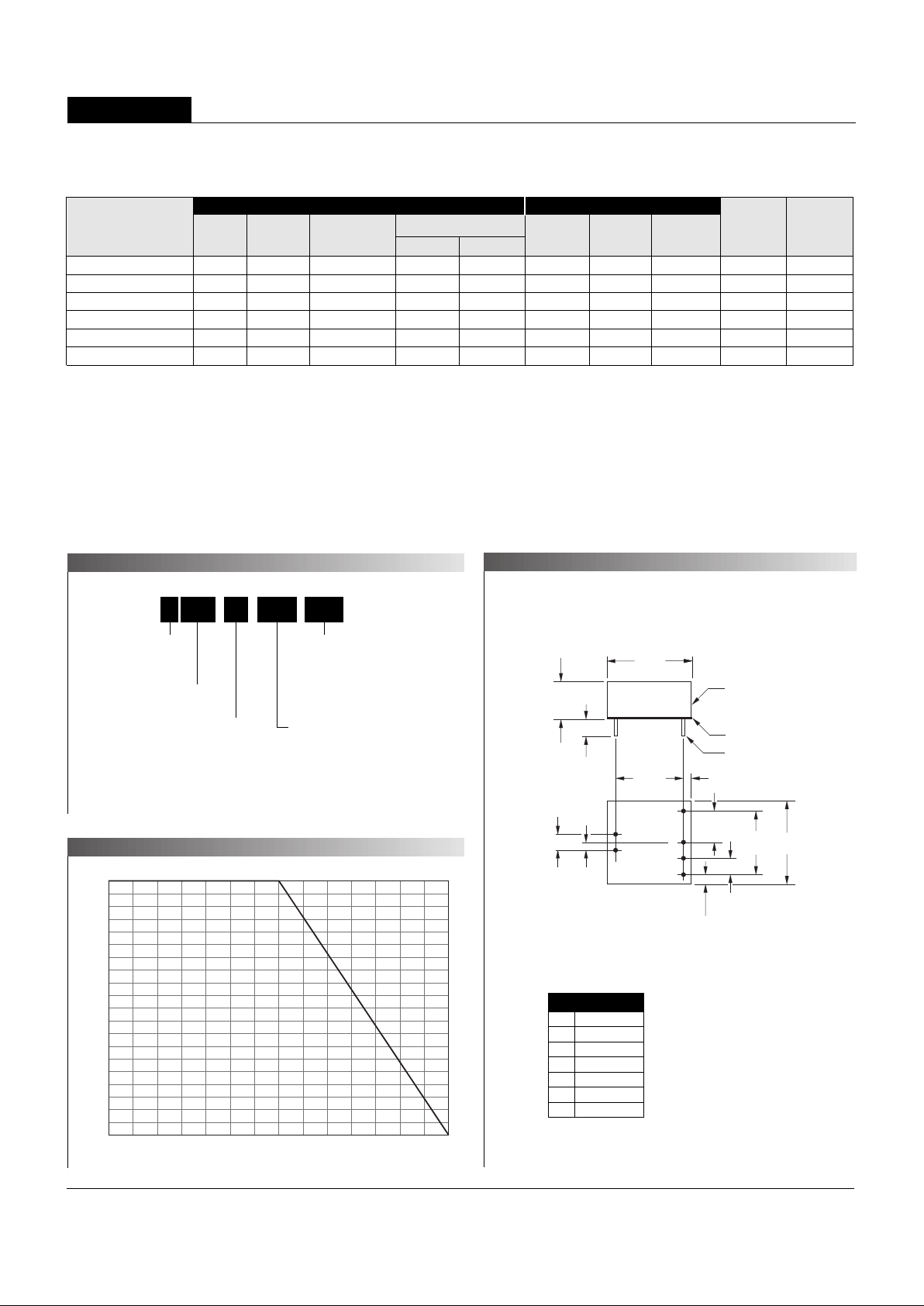
Output Power (Watts)
Ambient Temperature (°C)
–25 0 35 40 45 50 55 60 6 5 70 75 80 85 90 9
5
5
4.5
4
3.5
3
2.5
2
1.5
1
0.5
0
METAL CASE
INSULATED BASE
0.040 ±0.002 DIA.
(1.016 ±0.051)
1.00
(25.40)
0.45
(11.43)
0.20 MIN.
(5.08)
0.200
(5.08)
0.10
(2.54)
1.00
(25.40)
0.800
(20.32)
0.100
(2.54)
0.800
(20.32)
0.200
(5.08)
0.400
(10.16)
0.10
(2.54)
BOTTOM VIEW
3
1
2
4
6
5
MINIATURE, 5 WATT DC/DC CONVERTERS
XWR Series
2
Pin
1
2
3
4
5
6
I/O Connections
Function P4
+Input
–Input
+Output
Common
No Pin
–Output
Notes:
For "D24" models, the case
is connected to pin 2 (–V
IN).
For "D48" models, the case
is connected to pin 1 (+V
IN).
Case C7
Nominal Output Voltages:
±5, ±12 or ±15 Volts
Maximum Output Current
in mA from each output
Input V oltage Range:
D24 = 18-36 Volts (24V nominal)
D48 = 36-72 Volts (48V nominal)
Wide Range Input
Output Configuration:
B = Bipolar
15B WR 165 D48-/ -
➀
T ypical at TA = +25°C under nominal line voltage and full-load conditions unless otherwise noted.
➁
Ripple/Noise (R/N) measured over a 20MHz bandwidth.
➂
Balanced loads, 20% to 100% load.
➃
Nominal line voltage, no-load/full-load conditions.
Performance Specifications and Ordering Guide
➀
Ripple/Noise
➁
(mVp-p, Max.)
VOUT
(Volts)
Output
Package
(Case,
Pinout)
Efficiency
(Min.)
Regulation (Max.)
Line
VIN Nom.
(Volts)
Range
(Volts)Model
Input
IOUT
(mA, Max.)
IIN ➃
(mA, Max.)
Load
➂
BWR-5/500-D24 ± 5 ±500 150 ±2% ±2% 24 18-36 25/282 75% C7, P4
BWR-5/500-D48 ± 5 ±500 120 ±2% ±2% 48 36-72 25/141 75% C7, P4
BWR-12/210-D24 ±12 ±210 150 ±2% ±2% 24 18-36 25/264 80% C7, P4
BWR-12/210-D48 ±12 ±210 150 ±2% ±2% 48 36-72 25/133 80% C7, P4
BWR-15/165-D24 ±15 ±165 150 ±2% ±2% 24 18-36 25/260 80% C7, P4
BWR-15/165-D48 ±15 ±165 150 ±2% ±2% 48 36-72 25/130 80% C7, P4
PART NUMBER STRUCTURE
MECHANICAL SPECIFICATIONS
TEMPERATURE DERATING

MINIATURE, 5 WATT DC/DC CONVERTERS
BWR Models
3
Floating Outputs
Since these are isolated DC/DC converters, their outputs are "floating." Any
BWR model may be configured to produce an output of 10V, 24V or 30V
(for ±5V, ±12V or ±15V models, respectively) by applying the load across
the +Output and –Output (pins 3 and 6), with either output grounded. The
Common (pin 4) should be left open. Minimum 20% loading is recommended under these conditions.
Filtering and Noise Reduction
All BWR 5 Watt DC/DC Converters achieve their rated ripple and noise
specifications without the use of external input/output capacitors. In critical
applications, input/output ripple and noise may be further reduced by
installing low-ESR, tantalum or electrolytic capacitors across the input
and/or output terminals. Output capacitors should be connected between
their respective output pin (pin 3 or 6) and Common (pin 4)as shown in
Figure 2. The capacitors should be located as close to the power
converters as possible. Typical values are listed below. In many applications, using values greater than those listed will yield better results.
To Reduce Input Ripple
"D24" Models 20µF, 50V
"D48" Models 10µF, 100V
To Reduce Output Ripple
±5V Outputs 47µF, 10V, Low ESR
±12/15V Outputs 33µF, 20V, Low ESR
In critical, space-sensitive applications, DATEL may be able to tailor the
internal input/output filtering of these units to meet your specific requirements. Contact our Applications Engineering Group for additional details.
Performance/Functional Specifications
Input
Input V oltage Range:
"D24" Models 18-36 Volts (24V nominal)
"D48" Models 36-72 Volts (48V nominal)
Input Current See Ordering Guide
Input Filter Type
➁
LC on "D24" models
C on "D48" models
Reverse-Polarity Protection Yes (Instantaneous, 6A maximum)
OUTPUT
VOUT Accuracy (50% load):
±5V Outputs ±1.5%, maximum
±12/±15V Outputs ±1%, maximum
Temperature Coefficient ±0.02% per °C
Ripple/Noise (20MHz BW)
➁
See Ordering Guide
Line Regulation See Ordering Guide
Load Regulation See Ordering Guide
Efficiency See Ordering Guide
Isolation Volta ge
➂
1000Vdc, minimum
Current Limiting Auto-recovery
Overvoltage Protection Zener/transorb clamps
Dynamic Characteristics
Transient Response (50% load step) 500µsec max. to ±1.5% of final value
Switching Frequency 170kHz (±10kHz)
Environmental
Operating Temperature (ambient):
➃
Without Derating –25 to +60°C
With Derating to +95°C (See Derating Curve)
Storage Temperature –55 to +125°C
Physical
Dimensions 1" x 1" x 0.45" (25.4 x 25.4 x 11.4mm)
Shielding 5-sided
Case Connection:
"D24" Models Pin 2 (–V
IN)
"D48" Models Pin 1 (+VIN)
Case Material Corrosion resistant steel with
epoxy-based enamel finish
Pin Material Brass, solder coated
Weight 0.7 ounces (20 grams)
T ypical @ TA = +25°C under nominal line voltage and full-load conditions, unless noted.
➀
➀
These power converters require a minimum 20% loading to maintain specified regulation.
Operation under no-load conditions will not damage these devices; howe v er the y ma y not
meet all listed specifications.
➁
Application-specific internal input/output filtering can be recommended and perhaps added
internally on request. Contact DATEL Applications Engineering for details.
➂
Units can be screened or modified for higher guaranteed isolation voltages.
Contact DATEL Applications Engineering for details.
➃
Units can be screened for lower-temperature operation.
Contact DATEL Applications Engineering for details.
Input Voltag e:
"D24" Models 44 Volts
"D48" Models 88 Volts
Input Reverse-Polarity Protection Current must be <6A. Brief
duration only . Fusing recommended.
Output Overvoltage Protection
±5V Outputs 6.8 Volts, limited duration
±12V Outputs 15 Volts, limited duration
±15V Outputs 18 Volts, limited duration
Output Current Current limited. Max. current and
short-circuit duration are model
dependent.
Storage Temperature –55 to +125°C
Lead Temperature (soldering, 10 sec.) +300°C
These are stress ratings. Exposure of de vices to an y of these conditions ma y adv ersely
affect long-term reliability. Proper operation under conditions other than those listed in the
Performance/Functional Specifications Table is not implied.
ABSOLUTE MAXIMUM RA TINGS
TECHNICAL NOTES

4
MINIATURE, 5 WATT DC/DC CONVERTERS
XWR Models
Typical P erformance Curves (TA = +25°C)
The performance curves below were derived from actual test data for a single model number (BWR-15/165-D48).
Since all devices in this series have the same circuit topology, the perf ormance curves are representative of all devices.
EFFICIENCY VS. INPUT VOLTAGE AND OUTPUT LOAD
LOAD REGULATION
LINE REGULATION
30.3
30.2
30.1
30.0
29.9
29.8
29.7
Output Voltage Span (Volts)
Input Voltage (Volts
)
36 40 44 48 5 2 56 60 64 68 72
Output Voltage vs. Input Voltage
(Full-load con d it io n s . N ominal V
OUT
span = 30V)
85
84
83
82
81
80
79
36 42 48 54 60 66 7
2
Efficiency (%)
Input Voltage (Volts
)
Efficiency vs. Input Voltage
(Full-load conditions. Guaranteed efficiency = 80%
at V
IN
= 48V
)
84
82
80
78
76
74
72
33 66 99 132 165
Efficiency (%)
Output Currents (±mA)
Efficiency vs. Output Load
(VIN = nominal = 48V. Guaranteed efficiency at full load = 80%)
15.20
15.15
15.10
15.05
15.00
14.95
14.90
14.85
14.80
35 55 75 95 115 135 155 17
5
Output Voltage (±Volts)
–V
OUT
Output Current (mA
)
+V
OUT
–V
OUT
Output Voltage vs. Load (Unbalanced)
(V
IN
= nominal = 24V. Load on +V
OUT
fixed at 165mA)
30.3
30.2
30.1
30.0
29.9
29.8
29.7
Output Voltage Span (Volts)
Output Currents (±mA
)
35 45 55 65 75 85 95 105 115 125 135 145 155 165
Output Voltage vs. Load (Balanced)
(V
IN
= nominal = 48V. Nominal V
OUT
span = 30V)

–OUTPUT
+INPUT
–INPUT
+OUTPUT
1
2
3
6
COMMON
4
C
IN
C
OUT
C
OUT
+
+
+
5
If you’re designing with EMC in mind, please note that all of D ATEL ’ s BWR 5
Watt DC/DC Converters have been characterized for radiated and conducted
emissions in our new EMI/EMC laboratory . Testing is conducted in an EMCO
5305 GTEM test cell utilizing EMCO automated EMC test software. Radiated
emissions are tested to the limits of FCC Part 15, Class B and CISPR 22
(EN 55022) Class B. Correlation to other specifications can be supplied upon
request. Radiated emissions plots to FCC and CISPR 22 for model BWR-15/
165-D48 appear below . Its perf ormance is typical of all models in the Family .
Published EMC test reports are available for each model number. Contact
DATEL’s Applications Engineering Department for details.
Figure 2. Using External Capacitors to Reduce
Input/Output Ripple/Noise
Input Fusing
Certain applications and/or safety agencies may require the installation of
fuses at the inputs of power conversion components. For DATEL BWR
5 Watt DC/DC Converters, you should use slow-blow type fuses with values
no greater than 0.5A.
MINIATURE, 5 WATT DC/DC CONVERTERS
BWR Models
DATEL ’s world-class design, dev elopment and manufacturing team stands
ready to work with you to deliver the exact power converter you need for your
demanding, large volume, OEM applications. And ... we’ll do it on time and
within budget!
Our experienced applications and design staffs; quick-turn prototype capability;
highly automated, SMT assembly facilities; and in-line SPC quality-control
techniques combine to give us the unique ability to design and deliver any
quantity of power conv erters to the highest standards of quality and reliability .
We have compiled a large library of DC/DC designs that are currently used in a
variety of telecom, medical, computer, r ailway , aerospace and industrial
applications. We may already have the converter you need.
Contact us. Our goal is to provide you the highest-quality, most cost-eff ective
power converters available.
CUSTOM CAPABILITIES
EMI RADIATED EMISSIONS
80
70
60
50
40
30
20
10
0
–10
–20
Frequency (MHz
)
100
1000
Radiated Emissions
FCC Class B Limit
BWR-15/165-D48 Radiated Emissions
FCC Part 15 Class B, 3 Meters
Converter Output = ±15Vdc @ ±132mA
Radiated Emissions (dBµV/M)
BWR-15/165-D48 Radiated Emissions
EN 55022 Class B, 10 Meters
Converter Output = ±15Vdc @ ±132mA
80
70
60
50
40
30
20
10
0
–10
–20
100
1000
Radiated Emissions
EN 55022 Class B Limit
Radiated Emissions (dBµV/M)

6
DS0318 10/98
DATEL makes no representation that the use of its products in the circuits described herein, or the use of other technical information contained herein, will not infringe upon existing or future patent rights. The descriptions contained herein
do not imply the granting of licenses to make, use, or sell equipment constructed in accordance therewith. Specifications are s ubject to change without notice. The DATEL logo is a registered DATEL, Inc. trademark.
DATEL (UK) LTD. Tadley, England Tel: (01256)-880444
DATEL S.A.R.L. Montigny Le Bretonneux, France Tel: 01-34-60-01-01
DATEL GmbH München, Germany Tel: 89-544334-0
DATEL KK Tokyo, Japan Tel: 3-3779-1031, Osaka Tel: 6-354-2025
DATEL, Inc. 11 Cabot Boulevard, Mansfield, MA 02048-1151
Tel: (508) 339-3000 (800) 233-2765
Fax: (508) 339-6356 Email: datellit@mcimail.com
Data Sheet Fax Back:(508) 261-2857
MINIATURE, 5 WATT DC/DC CONVERTERS
XWR Series
INNOVATION and EX C ELL E N C
E
®
®
ISO 9001
I
SO 9001
REGISTERED
 Loading...