

Datasheet BPB-12-1.65-Q48, BPB-12-1.65-Q12, BPB-12-1.65-D48, BPB-12-1.65-D24, BPB-5-4-Q48 Datasheet (DATEL)
...
DATEL, Inc., Mansfield, MA 02048 (USA) • Tel: (508)339-3000, (800)233-2765 Fax: (508)339-6356 • Email: sales@datel.com • Internet: www.datel.com
INNOVATION and EX C ELL E N C E
®
®
Dual Output
BPB Models
High-Efficiency, Smaller-Package
25-40 Watt, DC/DC Conver ters
Features DATEL’s new BPB Model, 25-40 Watt, dual-output DC/DC con verters bring you
efficient "on-board" power processing in a cost-effective smaller package with a
standard pinout. The 2" x 3" BPB "footprint" conforms to the industry-standard pinout
and pin geometries of most 3" x 3" devices (a 33% space savings) while delivering as
much as 60% more power (40W vs. 25W).
Applicable to a wide range of telecom, computer and other OEM applications, BPB
Model DC/DC’s off er ±5V , ±12V or ±15V outputs. They operate from four diff erent input
voltage ranges with total available output power being a function of the selected input
range. "Q12" models operate from 10-36V and deliver 25W .
"Q48" models operate from 18-72V and deliver 30W . For "D24" and "D48" models, the
input voltage ranges and rated output powers are 18-36V at 35W and 36-72V
at 40W, respectiv ely .
For improved reliability and aff ordability , BPB Models exploit modern, high-speed,
automatic assembly to construct their field-proven, SMT-on-pcb designs. Devices
employ corrosion-resistant steel cases with heavy zinc top plates (traditionally referred
to as baseplates). Heat-generating transformer cores and power semiconductors are
mounted directly to the cases, which have threaded inserts for optional add-on heat
sinks and/or pcb mounting.
All devices feature input pi filters, input overvoltage shutdown, output overvoltage
protection, output current limiting, and thermal shutdown. UL, CSA, EN and IEC
compliance testing is currently in progress as are EMI/EMC characterizations.
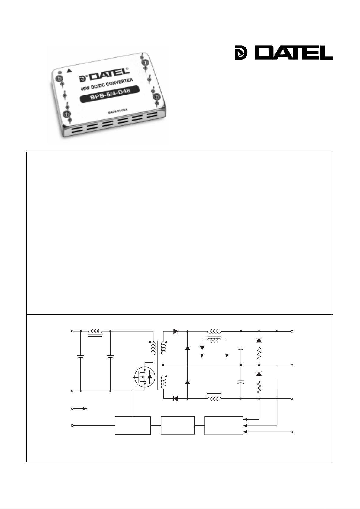
Figure 1. Simplified Schematic
OPTO
FEEDBACK
REFERENCE &
ERROR
AMPLIFIER
PWM
CONTROLLER
+V
IN
–
V
IN
ON/OFF
CONTROL
(SYNC)
TRIM
COMMON
+V
OUT
–
V
OUT
CASE
–
V
IN
PWM
■
■■
■■
■
■■
■■
■
■■
■■
■
■■
■■
■
■■
■■
■
■■
■■
■
■■
■■
■
■■
■■
■
■■
■■
■
■■
■■
■
■■
■■
■
25/30/35/40W output power
Standard pinout! Smaller size!
New 2" x 3" package fits 3" x 3" footprint
±5V, ±12V or ±15V outputs
Four input voltage ranges:
10-36V , 18-36V
18-72V , 36-72V
High efficiencies (to 88%)
Fully isolated, 750Vdc guaranteed
Fully I/O protected
Thermal shutdown
V
OUT trim and on/off control
Safety approvals pending
Modifications and customs for OEM’ s
25-40W, DUAL OUTPUT DC/DC CONVERTERS
XPB Series
2
As shown below, BPB Model DC/DC Converters are classified by output
power. For dual-output devices, the total output power from the two outputs
can not exceed the rated power. For example, "Q48" models have a
maximum output power of 30W. Therefore, if the +Output is sourcing 20
Watts, the –Output is limited to sourcing 10 Watts ensuring the total output
power does not exceed 30 Watts.
Output Configuration:
B = Bipolar
Nominal Output Voltages:
±5, ±12 or ±15 Volts
5B PB 4-
/
D48-
Input Volta ge Range:
Q12 = 10-36 Volts (24V nominal)
D24 = 18-36 Volts (24V nominal)
Q48 = 18-72 Volts (48V nominal)
D48 = 36-72 Volts (48V nominal)
Maximum Output Current
in Amps from each output
Power Package with
Metal Baseplate
➀
T ypical at TA = +25°C under nominal line voltage and balanced "full-load" conditions unless otherwise noted.
For BPB devices, "full load" is a function of each de vice's input voltage range. See Output Po wer Considerations and T echnical Notes f or more details .
➁
Ripple/Noise (R/N) measured over a 20MHz bandwidth.
➂
Balanced loads, 10% to 100% load.
➃
Nominal line voltage, no-load/full-load conditions.
Performance Specifications and Ordering Guide
R/N (mVp-p)
➁
Load
➂
VOUT
(Volts)
Package
(Case,
Pinout)
Efficiency
Regulation (Max.)
Line
VIN Nom.
(Volts)
Range
(Volts)Model
IIN ➃
(mA)
➀
Max.
Typ.
Typ.
Min.
BPB-5/4-Q12 ±5 ±4 100 150 ±0.5% ±1% 24 10-36 15/1225 82% 85% C10, P15
BPB-5/4-D24 ±5 ±4 100 150 ±0.5% ±1% 24 18-36 15/1696 84% 86% C10, P15
BPB-5/4-Q48 ±5 ±4 100 150 ±0.5% ±1% 48 18-72 25/735 82% 85% C10, P15
BPB-5/4-D48 ±5 ±4 100 150 ±0.5% ±1% 48 36-72 20/980 83% 85% C10, P15
BPB-12/1.65-Q12 ±12 ±1.65 100 150 ±0.5% ±1% 24 10-36 15/1224 82% 85% C10, P15
BPB-12/1.65-D24 ±12 ±1.65 100 150 ±0.5% ±1% 24 18-36 15/1667 85% 87% C10, P15
BPB-12/1.65-Q48 ±12 ±1.65 100 150 ±0.5% ±1% 48 18-72 15/727 84% 86% C10, P15
BPB-12/1.65-D48 ±12 ±1.65 100 150 ±0.5% ±1% 48 36-72 15/948 85% 87% C10, P15
BPB-15/1.3-Q12 ±15 ±1.3 100 150 ±0.5% ±1% 24 10-36 20/1225 83% 85% C10, P15
BPB-15/1.3-D24 ±15 ±1.3 100 150 ±0.5% ±1% 24 18-36 15/1648 85% 88% C10, P15
BPB-15/1.3-Q48 ±15 ±1.3 100 150 ±0.5% ±1% 48 18-72 15/735 83% 85% C10, P15
BPB-15/1.3-D48 ±15 ±1.3 100 150 ±0.5% ±1% 48 36-72 20/923 85% 88% C10, P15
IOUT
(Amps)
PART NUMBER STRUCTURE
Model Maximum Output Power
"Q12" 25 W atts
"Q48" 30 W atts
"D24" 35 Watts
"D48" 40 Watts
I/O Connections
Function P15
No Pin
–Input
+Input
Case
On/Off Control*
–Output
No Pin
Common
+Output
Trim
Pin
1
2
3
4
5
6
7
8
9
10
* See note 4 on next page.
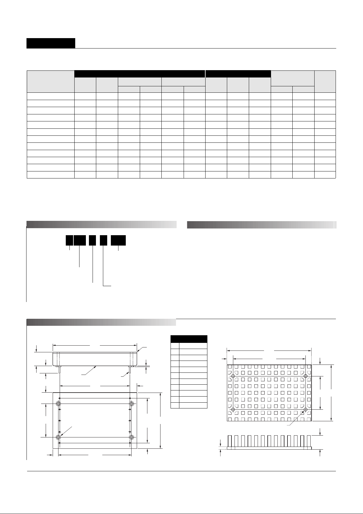
MECHANICAL SPECIFICATIONS
BOTTOM VIEW
2.500
(63.50)
0.25
(6.35)
2.00
(50.80)
7
6
8
9
1.600
(40.64)
4 EQ. SP. @
0.400 (10.16)
4
1
2
0.20
(5.08)
1.200
(30.48)
2.600
(66.04)
0.40
(10.16)
3.00
(76.20)
(4) THREADED INSERTS
#4-40 THD THRU
WITH 0.025 (0.64)
STANDOFFS
0.20
(5.08)
3
5
10
0.50
(12.70)
0.20 MIN.
(5.08)
0.040 ±0.002 DIA.
(1.016 ±0.051)
0.025
(0.64)
METAL CASE
METAL
BASEPLATE
Case C10
2.600
(66.04)
0.20
(5.08)
2.00
(50.80)
1.200
(30.48)
3.00
(76.20)
0.50
(12.70)
0.40
(10.16)
0.10
(2.54)
0.120 DIA. (3.048)
(4 PLACES)
MATERIAL: BLACK ANODIZED ALUMINUM
4 MOUNTING SCREWS AND 0.009 (0.229) THERMAL PAD INCLUDED
TOP VIEW
Optional Heat Sink (Part Number HS-23)
OUTPUT POWER CONSIDERATIONS
Output Input

BPB Models
25-40W, DUAL OUTPUT DC/DC CONVERTERS
3
Floating Outputs
Since these are isolated DC/DC converters, their outputs are "floating." Any
BPB model may be configured to produce an output of 10V, 24V or 30V (for
±5V, ±12V or ±15V models, respectively) by applying the load across the
+Output and –Output (pins 9 and 6), with either output grounded. The
Common (pin 8) should be left open. Minimum 20% loading is recommended under these conditions. The total output voltage span may be
externally trimmed as described below.
Performance/Functional Specifications
T ypical @ TA = +25°C under nominal line voltage and "full-load" conditions, unless noted.
➀ ➁
Input
Input Voltage Range:
"Q12" Models 10-36 Volts (24V nominal)
"D24" Models 18-36 Volts (24V nominal)
"Q48" Models 18-72 Volts (48V nominal)
"D48" Models 36-72 Volts (48V nominal)
Input Current See Ordering Guide
Input Filter Type
➂
Pi
Overvoltage Shutdown:
"Q12" and "D24" Models 40 Volts
"Q48" and "D48" Models 80 Volts
Reverse-Polarity Protection Yes (Instantaneous, 6A maximum)
On/Off Control (Pin 5)
➃
TTL high (or open) = on, low = off
Output
VOUT Accuracy (50% load) ±1%, maximum
Temperature Coefficient ±0.02% per °C
Ripple/Noise (20MHz BW)
➂
See Ordering Guide
Line/Load Regulation See Ordering Guide
Efficiency See Ordering Guide
Isolation Voltage 750Vdc, minimum
Isolation Capacitance 620pF
Current Limiting Continuous, auto-recovery
Overvoltage Protection Zener/transorb clamps, magnetic feedback
Dynamic Characteristics
Transient Response (50% load step) 300µsec max. to ±1.5% of final value
Switching Frequency 125kHz (±10%)
Environmental
Operating Temperature (ambient):
Without Derating –25 to +50°C (Model dependent)
With Derating to +90°C (See Derating Curves)
Maximum Baseplate Temperature +90°C
Storage Temperature –40 to +105°C
Physical
Dimensions 2" x 3" x 0.5" (50.8 x 76.2 x 12.7mm)
Shielding 6-sided
Case Connection Pin 4
Case Material Tin-plated steel
Baseplate Material Zinc with black enamel finish
Pin Material Brass, solder coated
Weight 4 ounces (113 grams)
➀
These converters require a minimum 10% loading on each output to maintain
specified regulation. Operation under no-load conditions will not damage these devices;
however they ma y not meet all listed specifications.
➁
"Full load" varies by part number and is determined by the input voltage range as indicated by
the part number suffix. See Technical Notes and Output Power Considerations .
➂
Application-specific input/output filtering can be recommended or perhaps added internally
upon request. Contact DATEL Applications Engineering for details.
➃
Applying a voltage to the On/Off Control pin when no input power is applied to the converter
can cause permanent damage to the converter. If desired, the On/Off Control function can be
replaced with a Sync function. See page 6 of this data sheet for more details.
Filtering and Noise Reduction
All BPB 25-40 Watt DC/DC Converters achieve their rated ripple and noise
specifications without the use of external input/output capacitors. In critical
applications, input/output ripple and noise may be further reduced by
installing electrolytic capacitors across the input terminals and/or low-ESR
tantalum or electrolytic capacitors across the output terminals. Output
capacitors should be connected between their respective output pin (pin 6 or
9) and Common (pin 8). See Figure 7. The caps should be located as close
to the power converters as possible. Typical values are listed in the tables
below. In many applications, using values greater than those listed will yield
better results.
To Reduce Input Ripple
"Q12, D24" Models 47µF, 50V
"Q48, D48" Models 10µF, 100V
To Reduce Output Ripple
±5V Outputs 47µF, 10V, Low ESR
±12/15V Outputs 22µF, 20V, Low ESR
In critical, space-sensitive applications, DATEL may be able to tailor the
internal input/output filtering of these devices to meet your specific requirements. Contact our Applications Engineering Group for additional details.
Input Voltage:
"Q12/D24" Models 44 Volts
"Q48/D48" Models 88 Volts
Input Reverse-Polarity Protection Current must be <6A. Brief
duration only . Fusing recommended.
Output Overvoltage Protection
±5V Outputs 6.8 Volts, limited duration
±12V Outputs 15 Volts, limited duration
±15V Outputs 18 Volts, limited duration
Output Current Current limited. Max. current and
short-circuit duration are model
dependent.
Storage Temperature –40 to +105°C
Lead Temperature (soldering, 10 sec.) +300°C
These are stress ratings. Exposure of de vices to an y of these conditions ma y adv ersely
affect long-term reliability. Proper operation under conditions other than those listed in the
Performance/Functional Specifications Table is not implied.
Absolute Maximum Ratings
TECHNICAL NOTES
Input Fusing
VIN Range "Q12" "D24" "Q48" "D48"
Fuse Value 4A 4A 3A 2A

25-40W, DUAL OUTPUT DC/DC CONVERTERS
XPB Series
4
Temperature Derating and Electrical Performance Curves
Q12 Models (25 Watts)
Output Power (Watts)
Ambient Temperature (°C)
25
20
15
10
5
0
Natural Convection Cooling
150 Linear Feet Per Minute
300 Linear Feet Per Minute
–25 0 20 25 30 35 40 45 50 55 60 65 70 75 80 85 90
Output Power (Watts)
Ambient Temperature (°C)
25
20
15
10
5
0
Natural Convection Cooling
150 Linear Feet Per Minute
300 Linear Feet Per Minute
–25 0 20 25 30 35 40 45 50 55 60 65 70 75 80 85 9
0
Figure 2a. Temperature Derating Without Heat Sink
Figure 2b. Temperature Derating With Heat Sink
Output Power (Watts)
Ambient Temperature (°C)
30
25
20
15
10
5
0
Natural Convection Cooling
150 Linear Feet Per Minute
300 Linear Feet Per Minute
–25 0 20 25 30 35 40 45 50 55 60 65 70 75 80 85 90
Output Power (Watts)
Ambient Temperature (°C
)
30
25
20
15
10
5
0
Natural Convection Cooling
150 Linear Feet Per Minute
300 Linear Feet Per Minute
–25 0 20 25 30 35 40 45 50 55 60 65 70 75 80 85 9
0
Figure 3a. Temperature Derating Without Heat Sink
Figure 3b. Temperature Derating With Heat Sink
Q48 Models (30 Watts)
Output Power (Watts)
Ambient Temperature (°C)
35
30
25
20
15
10
5
0
Natural Convection Cooling
150 Linear Feet Per Minute
300 Linear Feet Per Minute
–25 0 20 25 30 35 40 45 50 55 60 65 70 75 80 85 90
Output Power (Watts)
Ambient Temperature (°C)
35
30
25
20
15
10
5
0
Natural Convection Cooling
150 Linear Feet Per Minute
300 Linear Feet Per Minute
–25 0 20 25 30 35 40 45 50 55 60 65 70 75 80 85 9
0
Figure 4a. Temperature Derating Without Heat Sink
Figure 4b. Temperature Derating With Heat Sink
D24 Models (35 Watts)

BPB Models
25-40W, DUAL OUTPUT DC/DC CONVERTERS
5
40
35
30
25
20
15
10
5
0
Output Power (Watts)
Ambient Temperature (°C)
–25 0 20 25 30 35 40 45 50 55 60 65 70 75 80 85 9
0
Natural Convection Cooling
150 Linear Feet Per Minute
300 Linear Feet Per Minute
Figure 5a. Temperature Derating Without Heat Sink
Figure 5b. Temperature Derating With Heat Sink
D48 Models (40 Watts)
Output Power (Watts)
Ambient Temperature (°C)
40
35
30
25
20
15
10
5
0
–25 0 20 25 30 35 40 45 50 55 60 65 70 75 80 85 9
0
Natural Convection Cooling
150 Linear Feet Per Minute
300 Linear Feet Per Minute
Temperature Derating and Electrical Performance Curves
Voltage Output
Model Number Range Power ±5V Currents ±12V Currents ±15V Currents
BPB-5/4-Q12 10-36V 25 Watts ±2.5A (25W) – –
BPB-5/4-Q48 18-72V 30 Watts ±3A (30W) – –
BPB-5/4-D24 18-36V 35 Watts ±3.5A (35W) – –
BPB-5/4-D48 36-72V 40 Watts ±4A (40W) – –
BPB-12/1.65-Q12 10-36V 25 Watts – ±1.04A (24.96W) –
BPB-12/1.65-Q48 18-72V 30 Watts – ±1.25A (30W) –
BPB-12/1.65-D24 18-36V 35 Watts – ±1.46A (35W) –
BPB-12/1.65-D48 36-72V 40 Watts – ±1.67A (40.1W) –
BPB-15/1.3-Q12 10-36V 25 Watts – – ±833mA (24.99W)
BPB-15/1.3-Q48 18-72V 30 Watts – – ±1A (30W)
BPB-15/1.3-D24 18-36V 35 Watts – – ±1.17A (35.1W)
BPB-15/1.3-D48 36-72V 40 Watts – – ±1.33A (39.9W)
Definition of "Full Load" for Specification Purposes
Output Power
BPB Model, dual-output DC/DC converters incorporate a design tradeoff
between total available output power and input voltage range. The total
available power is a function of both the nominal input voltage and the
"width" of the input voltage range. For a given nominal input (24V or 48V),
narrower ranges (2:1 vs. 4:1) have more available power. For a given "width"
of input range (2:1 or 4:1), higher nominal inputs (48V vs. 24V) have more
available power. Each device, as indicated by its part-number suffix (Q12, Q48,
D24 or D48) has a total output power limitation of 25, 30, 35 or 40 Watts,
respectively. Observing these power limitations is the user's responsibility.
As indicated by its Part Number Structure, each ±5V, ±12V or ±15V BPB
device is capable of sourcing up to ±4, ±1.65 or ±1.3 Amps, respectively.
Users have the flexibility of loading either output up to these limits; however
you must be extremely careful not to exceed the total output power rating of
any given device. If, for example, a ±5V device with a 30W power rating
(BPB-5/4-Q48) is sourcing 4A from its +5V output (representing 20W of
+Output power), that device can only supply an additional 10W (2 Amps)
from its –Output.
As a consequence of this "power-allocation" flexibility, the definition of "full
load," as the condition under which performance specifications are tested and
listed, is ambiguous. The following table lists the positive and negative output
currents that DATEL uses to define each device’s "full load."
Table 1. Output Currents Comprising "Full Load"

25-40W, DUAL OUTPUT DC/DC CONVERTERS
XPB Series
66
DATEL makes no representation that the use of its products in the circuits described herein, or the use of other technical information contained herein, will not infringe upon existing or future patent rights. The descriptions contained herein
do not imply the granting of licenses to make, use, or sell equipment constructed in accordance therewith. Specifications are s ubject to change without notice. The DATEL logo is a registered DATEL, Inc. trademark.
DATEL (UK) L TD. T adle y, England Tel: (01256)-880444
DATEL S.A.R.L. Montign y Le Bretonneux, France Tel: 01-34-60-01-01
DATEL GmbH München, Germany Tel: 89-544334-0
DATEL KK Tokyo, J apan Tel: 3-3779-1031, Osaka Tel: 6-354-2025
DATEL, Inc. 11 Cabot Boulevard, Mansfield, MA 02048-1151
Tel: (508) 339-3000 (800) 233-2765 Fax: (508) 339-6356
Internet: www.datel.com Email: sales@datel.com
Data Sheet Fax Back:(508) 261-2857
DS-0410 10/98
On/Off Control (Standard)
The On/Off Control pin (pin 5) may be used for remote on/off operation. As
shown in Figure 6, the control pin has an internal 10kΩ pull-up resistor to
approximately 10V. The converter is designed so that it is enabled when the
control pin is left open (normal mode) and disabled when the control pin is
pulled low (to less than +0.8V relative to –Input, pin 2).
Dynamic control of the on/off function is best accomplished with a mechanical relay or an open-collector/open-drain drive circuit (optically isolated if
appropriate). The drive circuit should obviously be able to sink approximately
1mA when activated and withstand more than 10 Volts when deactivated.
Applying an external voltage to pin 5 when no input power is applied to the
converter can cause permanent damage to the converter. The on/off control
function, however, is designed such that the converter can be disabled (pin 5
pulled low) while input power is ramping up and then "released" once the
input has stabilized. Under these circumstances, it takes approximately
30ms for the output of the fully loaded DC/DC to ramp up and settle to within
±1% of its final value after the converter has been turned on.
Synchronization (Optional)
In critical applications employing multiple switching DC/DC converters, it may
be desirable to intentionally synchronize the switching of selected converters
(so the system noise can be reduced with notch filtering) or to purposely
desynchronize the converters (to lessen the current-carrying requirements on
intermediate dc buses). BPB DC/DC Converters have been designed so that
the On/Off Control function on pin 5 can be replaced with a Sync function. This
change has to be implemented by DATEL during the product assembly
process. Contact our Applications Engineering Group for additional details.
To synchronize the switching of multiple BPB converters configured with the
Sync function, an external clock can be applied to pin 5 of each converter.
The clock should be a TTL square wave referenced to –Input (logic high =
+2 to +5 Volts, 250µA max.; logic low = 0 to +0.8 Volts, 70µA max.) with a
maximum 1µsec "high" duration. The frequency of the synchronizing clock
should be higher than that of any individual converter. Therefore, it should be
145kHz ±5kHz.
Output Trimming
The total o ut p u t vo l t age span, from +Output (pin 9) to –Output (pin 6) may
be trimmed ±5% via a single trimpot or fixed resistor. The trimpot should be
connected as shown in Figure 8 with its wiper connected to pin 10 (Trim). A
trimpot can also be used to determine the value of a single fixed resistor
which can be connected between pin 10 (Trim) and pin 9 (+Output) to trim
"down" the output voltages, or between pins 10 (Trim) and 6 (–Output) to
trim "up" the output voltages. Fixed resistors should be metal-film types with
absolute TCR's less than 100ppm/°C to ensure stability.
Figure 7. Using External Capacitors
to Reduce Input/Output Ripple/Noise
Figure 8. Trim Connections Using a Trimpot
–OUTPUT
+INPUT
–INPUT
+OUTPUT
3
2
9
6
COMMON
8
C
IN
C
OUT
C
OUT
+
+
+
20k
Ω
5-10
Turns
+INPUT
–INPUT
TRIM
COMMON
3
2
9
6
8
LOAD
LOAD
10
–OUTPUT
+OUTPUT
Case Connection
Unlike most other DC/DC converters, BMP DC/DC's do not have their metal
case connected to one of their input pins. The "uncommitted" case is
connected to pin 4 which, depending on your system configuration, should be
connected to either +Input (pin 3) or –Input (pin 2).
+INPUT
–INPUT
3
2
+10V
10kΩ
5
ON/OFF
CONTROL
Figure 6. Driving the On/Off Control Pin
INNOVATION and EX C ELL E N C
E
®
®
ISO 9001
I
SO 9001
REGISTERED
 Loading...