

Page 1
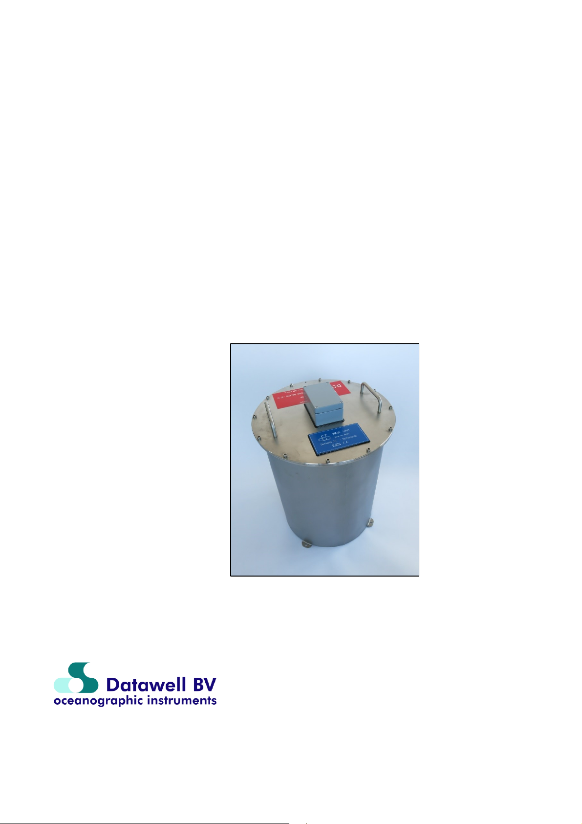
Wave Unit
Reference Manual
April 15, 2019
Service & Sales
Voltastr aat 3
1704 RP Heerhugowaard
The Neth erlands
+31 72 534 5298
+31 72 572 6406
www.datawell. nl
Page 2

2
Page 3

3
Page 4

4
Declaration of conformity
(According to EN ISO/IEC 17050-1:2004)
Document No.: Datawell_DoC_Wave_Unit_1_1
Manufacturer's name: Datawell B.V.
Manufacturer's address: Zomerluststraat 4
2012 LM Haarlem
The Netherlands
Declares under sole responsibility that the product:
Product name: Waverider
Trade name: Datawell
Model: Wave Unit
complies with the essential requirements of the following applicable European Directives,
and carries the CE marking accordingly:
EMC Directive (2004/108/EC)
RoHS Directive (2011/65/EU)
and conforms with the following product standards:
Standard Limit
EMC EN 300 220-1 V2.4.1 (2012-05) −54 dBm, 47-74, 87.5-118, 174-230, 470-862
MHz
EN 300 220-2 V2.4.1 (2012-05) −36 dBm, <1000 MHz, −30 dBm, >1000 MHz
EN 300 390-1 V1.2.1 (2000-09) −36 dBm, 30 MHz-1 GHz
EN 300 390-2 V1.1.1 (2000-09) −30 dBm, 1-4 GHz
EN 301 489-1 V1.9.2 (2011-09) / 3 V/m, 80-2700 MHz
EN 301 489-3 V1.4.1 (2011-09) 4 KV/8 KV contact/air
EN 55022: 2010 / 40 dB(μV/m), 30-230 MHz
EN 61000-6-3: 2007 47 dB(μV/m), 230-1000 MHz
EN 55024: 2010 / 3 V/m, 80-2700 MHz
EN 61000-6-1: 2005 4 KV/8 KV contact/air
Supplementary Information:
This DoC applies to above-listed products placed on the EU market after:
Jan 1, 2017 Eric Stoker
Date Quality Assurance Manager
Page 5

5
Contents
1 Introduction ................................................................................................... 7
2 Maintenance ................................................................................................... 9
2.1 Consumables ........................................................................................... 9
2.1.1 Bags of drying agent ......................................................................... 9
2.2 Inspection ................................................................................................. 9
2.2.1 Damage ............................................................................................ 9
2.2.2 Opening the Wave Unit and sealing rings ......................................... 9
2.3 Service ..................................................................................................... 9
2.3.1 The Wave Unit’s wave motion sensor ............................................... 9
3 Trouble Shooting ......................................................................................... 11
3.1 Wave Unit diagnosis .............................................................................. 11
3.2 The Wave Unit motion sensors .............................................................. 11
3.2.1 Stabilized platform and accelerometer ............................................ 11
4 Repair ........................................................................................................... 13
4.1 Calibration .............................................................................................. 13
4.2 Contact ................................................................................................... 13
4.3 Serial numbers ....................................................................................... 13
5 Reference ..................................................................................................... 15
5.1 Dangers and warnings ........................................................................... 15
5.1.1 Dangers .......................................................................................... 15
5.1.2 Warnings ......................................................................................... 15
5.2 Measuring waves with the Wave Unit .................................................... 15
5.2.1 Measuring waves - Considerations ................................................. 15
5.2.2 Wave Unit parts .............................................................................. 16
5.2.3 Packing ........................................................................................... 16
5.2.4 Stainless steel housing ................................................................... 16
5.2.5 Lid Assembly ................................................................................... 17
5.2.6 Lid ................................................................................................... 17
5.3 Wave motion sensors ............................................................................. 18
5.3.1 Wave height, principle of measurement .......................................... 18
5.3.2 Wave direction, principle of measurement ...................................... 18
5.3.3 Wave Unit axes and references ...................................................... 19
5.3.4 Inspection of the fluid level .............................................................. 20
5.3.5 Sensor fluid and temperature .......................................................... 21
5.3.6 Calibration of the vertical accelerometer ......................................... 21
5.3.7 Platform offset and stability ............................................................. 21
5.3.8 Magnetic compass .......................................................................... 21
5.3.9 Pitch and roll ................................................................................... 22
5.3.10 Horizontal accelerometers ............................................................ 22
5.3.11 Filtering ......................................................................................... 22
5.4 Data processing ..................................................................................... 24
5.4.1 Wave height spectrum .................................................................... 24
5.4.2 Wave direction spectrum ................................................................. 25
5.5 Data format ............................................................................................ 27
Page 6

6
5.5.1 Wave Unit serial message format ................................................... 27
5.5.2 Datawell real-time format ................................................................ 28
5.6 Stainless steel housing and lid assembly ............................................... 31
5.6.1 Installation ....................................................................................... 31
5.6.2 Packing, weights and dimensions ................................................... 31
5.6.3 Wave Unit housing .......................................................................... 31
5.6.4 Handles ........................................................................................... 31
5.6.5 Lid, serial number and FS direction ................................................ 31
5.6.6 Drying agent bags, plywood ............................................................ 32
5.6.7 Lid and connections ........................................................................ 32
5.7 Power supply and consumption ............................................................. 34
5.8 Contacts and Questions ......................................................................... 34
5.8.1 Addresses ....................................................................................... 34
5.8.2 Telephone and fax numbers ........................................................... 34
5.8.3 Email-addresses ............................................................................. 34
5.8.4 Website ........................................................................................... 35
5.8.5 FAQ ................................................................................................ 35
5.8.6 Datawell Bulletin ............................................................................. 35
5.9 Literature ................................................................................................ 35
Page 7

7
1 Introduction
The Datawell Wave Unit is an OEM version of the well-known Directional Waverider Mk-III
for measuring wave motions in three directions. The unit gives out the real time heave, north
and west displacements as well as common wave parameters like Hs and Tz and spectral data.
The Wave Unit contains Datawell’s accurate and well-proven stabilized platform sensor,
enabling wave height measurements by a single accelerometer. For the wave direction, direct
pitch and roll measurements are performed needing no integration. This, in combination with
horizontal accelerometers and a compass, forms the complete sensor unit which is the heart of
the Wave Unit.
The Wave Unit is meant to be integrated as a complete sensor package in oceanographic and
meteorological buoys.
The Wave Unit is equipped with an RS-232 interface and a power converter. Both the power
converter and the RS-232 interface are galvanically isolated for easy integration and overall
robustness. The power converter is suitable to accept a wide input voltage range from 10V up to
30V DC. The data format of the Wave Unit is compatible with the format as sent out by a
DWR-MkIII and can be used with the Waves4 software package and/or libdatawell
library. Alternatively, the data can be received, interpreted and forwarded by an embedded
system.
The Wave Unit is a highly sophisticated piece of equipment which hardly requires any attention.
For continuous reliable operation some maintenance is required however at low frequency
intervals. Chapter 2 Maintenance covers this topic.
In Chapter 3 Trouble Shooting several suggestions are made to tackle possible problems or even
carry out some small repairs.
During the operational life of your equipment calibration drift, aging or incidents could make it
necessary to send (part of) the equipment back to Datawell Service department. To serve you
best it is important to know exactly which parts fail and need to be returned. Please contact our
Service department prior to returning the equipment, stating serial number and complaint.
Chapter 4 Repair tells you where to locate serial numbers, how to contact Datawell Service
department and where to send parts.
This manual describes the operation of the following configuration:
Wave Unit with stabilized platform accelerometer-based wave motion sensor
Supply: 10 - 30 V DC, power consumption 400 mW max; reverse polarity and ESD
protected
Stainless Steel housing
Size (approximately): diameter 410 mm, height 560 mm
Weight (approximately): 36 kg
Do not expose your Wave unit to sea water, install in a water tight compartment.
Also keep away any magnetic parts, since they will interfere with the magnetic compass
measurements and affect the measured wave direction
Page 8

8 9
Page 9

2 Maintenance
During the operational life of your Wave Unit it will require some maintenance even though it
may function without error. We recommend to inspect the Wave Unit on every possible
occasion in order to prevent possible malfunctioning.
This chapter indicates which parts need servicing and when. Rather than extensively describing
the full maintenance procedure, this chapter gives a short summary. Please refer to the
description of the respective part in Chapter 5 Reference for the actual maintenance procedure.
2.1 Consumables
2.1.1 Bags of drying agent
In a hermetically sealed Wave Unit the bags with drying agent will protect the Wave Unit’s
electronics from taking up any possible moisture. In case the drying agent gets saturated it needs
to be dried in an oven, see subsection 5.6.6. Bags are located near the electronics in the lid
assembly and near the sensor electronics.
2.2 Inspection
2.2.1 Damage
We advise to inspect the Wave Unit for damage upon delivery.
2.2.2 Opening the Wave Unit and sealing rings
For reasons of importance it is noted in the beginning of the paragraph that before the lid is
opened, it should be rinsed with fresh water to avoid migration of salt and dirt into screw holes,
sealing ring grooves or the Wave Unit interior.
Remove dirt from the circular grooves of the housing flange and inspect the rubber sealing rings
for cuts. Clean grooves and intact sealing rings are essential for water tightness.
To open the lid refer to subsection 5.2.6.
2.3 Service
2.3.1 The Wave Unit’s wave motion sensor
The stabilized platform vertical accelerometer consists of a fluid-filled sphere. Over the years
the fluid evaporates through the Perspex sphere. Check the fluid level at least once every three
years. Experience showed that a small refill is required every three years. Section 5.3 will
explain where to check and how to refill.
As long as the sphere is correctly filled, the motion sensor is a robust sensor with nearly
perfectly buoyant invulnerable mechanics in the fluid. However, with insufficient fluid inside
the sphere, the mechanics in the fluid will no longer remain perfectly suspended and ultimately
will collapse under its own load. For a long life of your wave motion sensor carefully maintain
the sensor fluid level.
When in doubt, several tests in section 5.3 describe how to roughly verify the correct
functioning of your motion sensors.
Page 10

10 11
Page 11

3 Trouble Shooting
This chapter will deal with minor problems that may occur and can be traced and solved by
yourself.
3.1 Wave Unit diagnosis
The Wave Unit has been provided with a processor board, which processes the digital signals to
the serial communication channel. This channel is available for host access. For the processor
board is a common part in most products of Datawell’s product range, it has some redundant
circuitry when using it in this Wave Unit application.
3.2 The Wave Unit motion sensors
The stabilized platform motion sensor is a very delicate instrument that can only be repaired by
skilled persons. In this section the symptoms of malfunction will be described, but faults are
almost impossible to repair for a layman.
3.2.1 Stabilized platform and accelerometer
The strength of the Datawell stabilized platform is that the heave is only determined by the
vertical accelerometer sensor. This implies that an erratic heave directly points at the vertical
accelerometer. Apart from the heave also the offset of the vertical accelerometer in the system
file, subsection 5.5.2.3, can be inspected. Possible causes are damaged suspension or internal
wires, moisture on the electronics, or low battery voltage.
Platform instability typically produces long period oscillations (20-25 s) of significant
amplitude (on the order of a meter) in the horizontal displacements. A faulty inclination angle
supports this. Likely causes are turbulence in the fluid or a sudden temperature change. Too fast
rotations may also cause turbulence. These disturbances will disappear within 24 hours. It
should be noted that pitch and roll errors can produce similar symptoms.
3.2.2 Magnetic compass
Inclination is the angle the local earth magnetic field makes with the local earth surface. A
measured inclination angle which matches the true local inclination within 1.5º indicates that (1)
the compass is functioning well, and (2) the offset angle of the platform is not too large. Local
inclination may be found on the web, e.g. visit www.ngdc.noaa.gov/seg/geomag/magfield.shtml.
Orientation is the angle between the reference axis of the Wave Unit and the magnetic north
direction. It does not depend on any tilt. The V-shaped groove indicates the reference axis.
Orientation may be easily verified with help of a hand held magnetic compass or the known
local north.
Furthermore, a plot of the inclination as function of the orientation can be made. The inclination
should remain constant for different orientation angles. A dependency of inclination on buoy
orientation can be caused by a platform offset angle or by an offset of the fluxgate compass.
Page 12

12 13
Page 13

4 Repair
Datawell recommends you send your Wave Unit for service and maintenance every 3 to 6 years
approximately. Also if your Wave Unit does not function correctly and, although you may have
tracked down the problem with help of the Trouble shooting chapter, you are not able to solve
the problem, the malfunctioning Wave Unit (part) should be sent to Datawell Service
department. This chapter will explain where to turn for help and what information must be
provided that Datawell may swiftly remedy your problems.
4.1 Calibration
Datawell advises to have your Wave Unit recalibrated every 3 to 6 years. Assistance and
training: Datawell offers you to hire a service and repair specialist to train your personnel. If
you just purchased a wave measuring system you are entitled to one day of assistance and
training for free. Ask our Sales department or Service department.
4.2 Contact
To contact Datawell Service department, you can use the following address or numbers. If you
ship Wave Units or Wave Unit parts please use the same address.
Datawell BV
Voltastraat 3
1704 RP Heerhugowaard
The Netherlands
Phone +31-(0)72-5718219
Fax +31-(0)72-5712950
Email servdept@datawell.nl
If you use airfreight please use following address:
DATAWELL BV
c/o DHL Global Forwarding B.V.
PRESTWICKWEG 1
1118LC SCHIPHOL-SE
AMSTERDAM AIRPORT
THE NETHERLANDS
Notify: DATAWELL BV
TEL: 023 5316053
4.3 Serial numbers
If you have any questions regarding your Wave Unit or if you encounter problems and you wish
to contact Datawell, it is important to have the serial number at hand as listed on the text plate
on top of the Wave Unit.
Page 14

14
Page 15

15
5 Reference
This is the largest chapter by far. All Wave Unit functions and parts will be discussed here. To
start with, the various components of the Wave Unit, their names and location will be
introduced. You will be guided through the lid assembly and the stainless steel housing
assembly, and packing, first in general, then in detail. After that all possible standard functions
will follow. The chapter concludes with references to other sources of information and useful
addresses and contacts.
5.1 Dangers and warnings
Below you find a summary of dangers and warnings related to the present product.
5.1.1 Dangers
While transporting the Wave Unit, tie it down firmly. A Wave Unit moving
uncontrolled can be dangerous.
5.1.2 Warnings
Do not expose your Wave unit to sea water, install in a water tight compartment
Do not spin your Wave Unit more than 10 turns at once or faster than 1 turn/10s. This
may damage the motion sensor inside.
Do not expose your Wave Unit to temperatures below −5 ºC for longer periods; the
fluid in the sensor could be permanently altered.
Do not insert magnetic materials in or in the environment of the Wave Unit as this
will affect the magnetic compass readings. Use original Datawell parts.
Close the lid whenever the Wave Unit is not in use. Otherwise the bags of drying agent
inside the buoy will take up moisture and become saturated. Particularly for a cold
Wave Unit placed in a humid environment saturation will set in very fast.
5.2 Measuring waves with the Wave Unit
Datawell is specialized in the production of complete wave measuring equipment generating
high quality wave data and wave parameters for marine coastal engineering and scientific
institutes. Mooring lines, hull size and shape, wave motion sensors, etc. of all products are
designed and integrated specifically to serve this purpose. This Wave Unit however only
consists of the heart of such measuring equipment assembled in an stainless steel housing. The
accuracy of obtained data is highly dependent on the way the Wave Unit has been built into a
major assembly and the way this major assembly is moored, its buoyancy, etc.
5.2.1 Measuring waves - Considerations
If built into larger platforms, the following topics need to be reconsidered:
Wave lengths shorter than twice the diameter of the platform will not be measured
anymore. This will result in some high frequency cut-off in the generated spectra.
The reduced freedom of movement will result in a restriction mainly in the horizontal
direction, not so much in vertical direction. The problems in the horizontal direction are
its sign asymmetry (complete freedom of motion towards the mooring point and
absolutely no motion from the mooring point beyond the mooring line length) and
direction asymmetry (perpendicular to the mooring line the motion is nearly
unrestricted). This will slightly affect the estimated wave heights but may yield
misleading wave directions, depending on wave-, wind- and current direction.
Page 16

16
Another point to consider is that pitching and rolling of tall structures may introduce
non-wave motion away from the centre of rotation (pseudo-motion); horizontal motion
will be influenced most.
A final point of consideration: the response of the buoy or platform to the waves may
display resonant motion like immersion resonance or pitch/roll resonance at certain
frequencies.
5.2.2 Wave Unit parts
The Wave Unit is a hermetically closed stainless steel housing with the sensor, compass,
accelerometers and the analogue circuitry inside the stainless steel housing; the filter board, the
power supply with the serial communication circuitry and the power connection, the AD
converter and the processor board have been built onto the inside of the lid. On top of the Wave
Unit the connection box is available for making the connections to the host unit.
5.2.3 Packing
The Wave Unit is packed on a wooden plate, secured with 4 bolts and nuts.
5.2.4 Stainless steel housing
On the outside of the stainless steel housing you will find, from the bottom up: the mounting
flange, the cylindrical housing with in the upper flange, the forward shipping reference and the
groove for the rubber sealing ring; on top you will find the lid again with a matching forward
shipping reference, the handles and the connection box. The forward shipping reference is
formed by a V-shaped cutting.
Figure 5.2.4.1 shows the contents of the Wave Unit; the motion sensor package consisting of
(analogue) electronics boards, a stabilized platform with vertical accelerometer, and pitch-roll
sensors, two horizontal accelerometers and a three-axial fluxgate compass. To the top one can
see the lid assembly with the filter board, the AD board, the processor board and the power
supply board with the serial communication channel.
Figure 5.2.4.1 Rendering of the stainless steel housing contents
Page 17

17
To ensure proper functioning of all the electronics drying agent bags have been added at the
appropriate places.
5.2.5 Lid Assembly
A whole range of printed circuit boards each with its own functionality and its own location has
been positioned onto the lid assembly. Figure 5.2.5.1 schematically shows the location of the
boards; the interconnecting ribbon cables and other cables are not shown.
At the heart of the lid assembly you find the microprocessor board. It manages all processes,
commands and controls actions, observes status and health, collects data, processes data and
redistributes processed data and handles various means of communication. All interconnecting
ribbon cables start or end here. Another central board is the power supply. This board adapts the
applied power at the terminal box at the top of the lid to voltages required to power the boards.
This board also contains the communication channel.
To perform the actual measurements, the analogue-to-digital converter board (ADC) samples
the buoy’s internal system temperature sensor which is present on the ADC board and all
motion sensors outputs and passes the readings on to the microprocessor. The data is processed
and made available at the serial communication terminal at the terminal box at the top of the lid.
Figure 5.2.5.1. Schematic drawing of the printed circuit boards on the lid assembly.
5.2.6 Lid
To close the lid 12 hexagon socket screws are used. One of these may be screwed in the 13th
lifting hole to overcome a possible partial vacuum when lifting the lid (Figure 5.2.6.1). The lid
can be lifted by using the treaded hole and one of the screws, in case of under pressure.
Page 18

18
Figure 5.2.6.1. Opening the lid by using a screw in the lifting hole.
5.3 Wave motion sensors
5.3.1 Wave height, principle of measurement
The Wave Unit measures wave height by means of a single accelerometer. The sensitive axis of
this accelerometer points in the vertical direction. After filtering and double integration of the
acceleration signal the motion of the Wave Unit, hence the wave motion is obtained. The
strength of the Datawell principle is its gravity-stabilized platform. This patented principle is
unique and we will come to the advantages below. Essentially, the platform is formed by a
suspended disk in a fluid of equal density. By means of a very small metal weight the disk is
made gravity sensitive. The large mass of the fluid in combination with the small force of the
metal makes a pendulum with a natural period of 40 s, corresponding to a pendulum length of
400 m. This platform remains almost horizontal under any movement which can be expected at
sea. Mounting the accelerometer on this stabilized platform makes the measurement of wave
height through vertical acceleration straightforward.
5.3.2 Wave direction, principle of measurement
Wave direction is determined by measurement of the horizontal motion of the Wave Unit and
correlating this motion with the vertical motion. Two mutually perpendicular accelerometers are
mounted in the Wave Unit which measure the horizontal motion in case the Wave Unit is in the
upright position. In case of tilt, the pitch and roll angles are determined by coils around the
sensor sensing the electromagnetic coupling with a coil on the stabilized platform. With the help
of the pitch and roll sensors the measurements of the above mentioned acceleration sensors are
Page 19

19
transferred to real horizontal acceleration. With the help of a fluxgate compass the acceleration
in Wave Unit coordinates is transferred to north-west-coordinates.
The beauty of the Datawell principle is that it has kept the vertical acceleration out of all the
transformations, thus ensuring that you get the best wave heights possible.
5.3.3 Wave Unit axes and references
The Wave Unit motion sensor package measures 8 observables: 3 accelerations Ax, Ay, Av, 3
magnetic field strengths Hx, Hy Hz, and pitch and roll. Figure 5.3.3.1 defines the directions of x,
y, z and vertical axes. All directions are referenced to the V-shaped groove (y) and normal (x),
the axis of rotation (z) fixed to the Wave Unit and the vertical axis (v) determined by the force
of gravity.
Suppose you were facing the V-shaped groove. Tilting the Wave Unit towards you would result
a positive pitch and a negative x-acceleration or Ax output. Note that an accelerometer sensor
actually is a force sensor and that with a tilted Wave Unit the force of gravity will act as an
inertial force. If you add that the direction of acceleration is opposite to the direction of the
inertial force or gravity force, you will understand why Ax is negative. Similarly, tilting the
Figure 5.3.3.1. Definition of the axes and signs of the motion sensors.
Page 20

20
Wave Unit towards the left would result a positive roll and a positive y-acceleration or Ay
output. Considering an upright Wave Unit, if the positive Ax direction would point towards the
north then the positive Ay direction would point westward and the positive z-axis would be
directed upward. Double integration would yield north, west and vertical motion.
The signs of the compass outputs correspond to the positive x-, y-, but negative z-direction.
Directing the V-shaped groove towards the north will yield a positive H x and zero orientation.
Looking from above a right angle clockwise rotation yields +90º orientation and a positive Hy.
Note that the Hz-axis is fixed to the housing whereas the Av-axis always points up and is fixed to
the stabilized platform.
For a tilted Wave Unit the orientation is the same as for an upright Wave Unit, which may be
verified by tilting the Wave Unit.
5.3.4 Inspection of the fluid level
As mentioned in Chapter 2 Maintenance it is important for the stabilized platform and vertical
accelerometer sensor to periodically check the fluid level within the plastic sphere. The fluid
level can be visually inspected through the Perspex lid on the sphere, see Figure 5.3.4-1. If the
centre of the rubber membrane is pointing upwards, Figure 5.3.4.1(b), the fluid level is
sufficient. In case the membrane touches the nylon screw, Figure 5.3.4.1(a), the fluid is too low
and fluid has to be added. Datawell advises to check the fluid level every 3 years. Based on
experience the sensor requires a small refill after 3 to 6 years.
Only fill up the sensor in a clean environment to avoid contamination of the fluid. Do not insert
anything but the original sensor fluid. Datawell will readily supply you with a small amount. To
avoid damage by spilled fluid wrap some tissue paper around the neck of the sensor. Take off
the plastic lid by unscrewing the 6 screw-bolts. Remove the rubber membrane and pour some
Figure 5.3.4.1. Examples of the fluid level of the stabilized platform and
vertical accelerometer sensor: (a) fluid level too low, (b) fluid level sufficient.
Page 21

21
fluid into the sensor until the level is about 1.5 cm below the top. Reposition the rubber
membrane without trapping air beneath it. Some deformation of the membrane may be
necessary to do so. Fasten the plastic lid again with the 6 screw-bolts. Remove the tissue and
wipe away all spilled fluid on the outside of the sensor.
5.3.5 Sensor fluid and temperature
It has been written repeatedly that the accelerometer based Wave Unit must not be stored below
temperatures of -5 ºC. This is determined by the freezing temperature of the fluid surrounding
the stabilized platform.
In practice, it may be inevitable to expose the Wave Unit to temperatures lower than -5 ºC. On a
short time scale this is acceptable as long as you consider the heat transfer from the sensor to the
outside.
5.3.6 Calibration of the vertical accelerometer
A calibrated vertical accelerometer and stabilized platform should perform within limits over 3
to 6 years, depending on operating conditions. Consequently Datawell recommends
recalibration of your buoy every 3 to 6 years. Calibration of the vertical accelerometer requires
special tooling and trained personnel. Please contact Datawell Service department.
5.3.7 Platform offset and stability
Here two tests are described that focus on the stabilized platform, more precisely its offset and
stability. Let us start with testing the offset. Place your Wave Unit upright on a revolving frame
or trolley. Rotate the frame or trolley 1.5 times 360º around the vertical axis and start logging
for 0.5-1 hour. Now plot the logged pitch and roll against each other and skip the first 1.5
minute or so. A circle should be written over a time lapse of approximately 30 minutes. The
radius of this circle represents the platform offset. It should stay below 1º.
To test the stability, leave the Wave Unit at rest on a trolley for a while. Then start logging the
Wave Unit motion. Push and stop the Wave Unit fiercely thus moving it a few metres. In
particular, the horizontal displacements will show disturbances at the natural swinging period of
40 s of the stabilized platform. If large disturbances occur at all kinds of frequencies, the
platform has become unstable. For example, this could be due to a separation of the sensor fluid
after cooling down to below −5 ºC. Compare doing the same experiment with a half-filled fishglobe. Contact Datawell Service department for repair.
5.3.8 Magnetic compass
The fluxgate compass measures the components of the earth magnetic field in three
perpendicular directions referenced to the Wave Unit’s frame: x-, y- and z-axis. The compass
consists of a stainless steel cube with three holes in three mutually perpendicular directions. In
each hole a magnetic field sensor is placed. This part requires extremely little service.
Before any checks can be carried out we must make sure that the local magnetic field is stable
and homogeneous. This is not a simple matter in many indoor situations with large DC currents
present or near iron structures. Two compass related outputs may be easily obtained: the
orientation of the Wave Unit and the local inclination of the earth magnetic field. By rotating
the Wave Unit over 90º or 180º angles the orientation angle can be checked. A correct (within a
few degrees) inclination angle indicates that: (1) the platform offset is small and (2) the compass
is functioning well. For optimum measurements the stabilized platform should be allowed some
20 min to come to rest. The inclination angle test should reproduce the same value when
rotating or tilting the buoy. Such behaviour in fact proofs that not only the platform offset is all
right but also pitch and roll and the three compass axes sensors function properly.
Page 22

22
5.3.9 Pitch and roll
Pitch and roll are measured through magnetic coupling between the pick-up coil on the platform
inside the sphere and the respective pair of pick-up coils outside the sphere. Also these sensors
hardly require service ever.
5.3.10 Horizontal accelerometers
Both fixed x- and y-accelerometers are contained in a small stainless steel can. The can is filled
with a fluid which has the same components as the fluid in the sphere, but in different ratio. In
contrast with the sphere, evaporation through steel is negligible and checking of the fluid level
is superfluous.
5.3.11 Filtering
The final goal is to measure the waves. Now there are two limitations that will keep the Wave
Unit from accurately measuring the waves. The following is however quite dependant on the
application the Wave Unit has been built-in, but at higher frequencies, when positioned in a hull
type of buoy, the wave wavelength becomes comparable to the buoy dimensions and the buoy
will not be able to follow the particular waves anymore (geometric attenuation). As higher
frequency measurements can only introduce noise, all analogue outputs of the Wave Unit’s
sensors are filtered by applying a low-pass filter with a cut off frequency of 1.5 Hz. The filtered
sensor outputs are then sampled and transformed to north, west and vertical accelerations all at a
rate of 3.84 Hz.
Another limitation comes from the sensors themselves. At the low frequency end accelerations
become very small and disappear in the sensor noise. Therefore, for the Wave Unit, a digital
high-pass filter with a cut off at 30 s is applied to the 3.84 Hz samples. At the same time it
converts the sample rate to 1.28 Hz. Finally, these accelerations are doubly integrated to give
the three-dimensional motion in the frequency range of 0.033-0.64 Hz.
Page 23

23
Specifications* for the Wave Unit when built into a 90 cm sphere and moored with a horizontal
Heave
Range
-20 m - + 20 m
Resolution
1 cm
Scale accuracy (gain error)
< 0.5% of measured value after calibration
<1.0% of measured value after 3 year
Zero offset
< 0.1 m
Period time*
1.6 s – 30 s
Cross sensitivity
< 3%
Direction
Range
0° - 360°
Resolution
1.5°
Heading error*
0.4° - 2° (depending on latitude) typical 0.5°
Reference
Magnetic north
Period time*
1.6 s – 30 s
Filter
Sampling frequency
3.84 Hz
Digital filtering type
phase-linear, combined band-pass
and double-integrating FIR filter
Filter delay
133.3 s
Band-pass characteristics
0.056-0.58 Hz: 0.03 dB
0.04-0.59 Hz: 0.3 dB
0.033-0.6 Hz: 3 dB
Low frequency side
24 dB/octave
High frequency side
> 60 dB
Port
RS-232, 8 bit, no parity, 1 stop bit, 9600 Baud
Format
Datawell real-time format
(displacements, wave parameters and spectral data)
Interface
Temperature range
operating –5 C - +35 C
storage –5 °C - + 40 °C (+55 C, short term, weeks only)
Supply
10 V - 30 V DC, ≤ 400 mW.
Protection against reverse polarity by a series diode.
Note: To avoid high inrush currents, it is recommended to
use a current limiter (>200mA).
General
Isolation
All inputs and outputs are galvanically isolated
Size
Diameter approx. 410 mm
Height over all approx. 560 mm
Weight
approx. 36 Kg
Material
housing stainless steel
elasticity of 30 N/m2. See Table 5.3.11.1.
Table 5.3.11.1 Specifications of Wave Unit.
Page 24

24
1
0
10/)/2exp()(
N
k
lkkll
NltNlfNklihwfHH
310
32
cos1
2
1
255
k
k
ww
kk
1
k
w
1
0
2
N
k
ksnorm
wfw
2
00
)( HfPSD
12/1)(
22
NlHHfPSD
lNll
2
2/2/
)(
NN
HfPSD
5.4 Data processing
The Wave Unit sensor generates raw north, west and vertical displacements at a rate of 1.28 Hz.
Displacements refer to excursions from the average position and should not be mistaken for
position changes relative to the previous position.
In oceanography the use of Fourier spectra of the vertical displacements to represent the wave
conditions is wide-spread. The power spectral density PSD thus obtained quickly shows what
wave amplitudes occur at what frequencies. The first part of this section is devoted to this
straightforward Fourier spectrum calculation. In the second part we will deal with a more
sophisticated Fourier analysis that also incorporates the horizontal motion. Now also
information on wave ellipticity, wave direction, direction spread, etc. becomes available.
5.4.1 Wave height spectrum
The internal wave spectrum is calculated as follows. At a sampling rate of fs = 1.28 Hz, every
200 seconds a total number of N=256 heave samples hk are collected
hk = h(kDt), k=0..N-1 (5.4.1-1)
where Dt=1/fs is the sampling time. A fast Fourier-transform (FFT) is applied to obtain a
spectrum in the frequency range 0 to fs/2 = 0.64 Hz, having a resolution of fs/N = 0.005 Hz.
The FFT yields Fourier coefficients according to:
(5.4.1-2)
with i = √(−1). The wk indicate the window coefficients. Datawell applies a cosine-shaped
window over the first and last 32 samples, according to
otherwise (5.4.1-3b)
(5.4.1-3a)
For normalization all window coefficients must be divided by
(5.4.1-4)
The power spectral density is obtained from the Fourier coefficients
(5.4.1-5a)
(5.4.1-5b)
(5.4.1-5c)
Page 25

25
where frequencies range from 0.0 Hz to 0.64 Hz in steps of 0.005 Hz. Actually, there is one
11
4
1
2
1
4
1
llll
PSDPSDPSDPSD
nfnfnf
iA
wfwfwf
iA
vfvfvf
iA
wfnfwfnfwfnfnw
AAC
nfvfnfvfnfvfvn
AAQ
0
vvwwnn
QQQ
0
nwwn
QQ
more step, all coefficients are smoothed according to
(5.4.1-6)
To limit the number of frequencies low frequency coefficients (fl ≤ 0.1 Hz) are left as they are,
while only every other smoothed coefficient on the high frequency side(fl > 0.1 Hz) is kept in
the spectrum file. Finally, 8 consecutive spectra covering 1600 s are averaged and used to
compute the half-hourly wave spectrum. Each half-integral hour (1800 s) a new cycle starts.
5.4.2 Wave direction spectrum
So far only the vertical displacements have been processed to give the wave power spectral
density. When north and west displacements are included into the processing, much more wave
information can be obtained. Starting from the time-series of north, west and vertical (n, w, v)
displacements, the three associated Fourier series may be calculated. Each Fourier series
consists of a number of Fourier coefficients, which in turn consist of a real and imaginary part.
Thus six Fourier components per frequency f are obtained αnf, βnf, αwf , βwf , αvf and βvf or in
vector notation:
(5.4.2-1a)
(5.4.2-1b)
(5.4.2-1c)
Building on this, co- (C) and quadrature-spectra or quad-spectra (Q) may be formed, e.g. (we
shall omit the frequency subscript hereafter)
(5.4.2-2)
(5.4.2-3)
In total 9 components arranged in a 3x3 matrix will be obtained for both co- and quad-spectra.
However, not all components need to be calculated. By definition we have
(5.4.2-4)
Furthermore, Q represents rotation. To give an example, a wave rolling eastward will have a
rotation component directed to the north (right-handed screw) and hence Qvw ≠ 0 and Qwv ≠ 0.
The rotation in the waves is particularly clear for breaking waves in the surf zone. A rotation
component directed vertically would represent eddy currents which are not part of the physics
of waves, therefore we also have
(5.4.2-5)
Page 26

26
vvvnvw
nvnnnw
wvwnww
CCC
CCC
CCC
0
00
00
vnvw
nv
wv
QQ
Q
Q
vvwwnn
nv
CCC
Q
a
1
vvwwnn
wv
CCC
Q
b
1
wwnn
wwnn
CC
CC
a
2
wwnn
nw
CC
C
b
2
2
),( fG
...2sin2cossincos
2
11
),(
2211
babafG
...)(2sin)(2cos)cos(
2
11
),(
020201
nmmfG
),arctan(
110
ab
2
1
2
11
bam
02022
2sin2cos
bam
02022
2cos2sin
ban
Thus, one obtains:
(5.4.2-6)
and
(5.4.2-7)
Given these components a whole set of informative wave parameters such as: wave direction,
direction spread, wave ellipticity can be obtained. Before discussing their meaning in more
detail, first, all formulas will be given.
(5.4.2-10)
(5.4.2-8)
(5.4.2-9)
These are the first four Fourier coefficients of the normalized directional distribution
(5.4.2-11)
(5.4.2-12)
alternatively cast as
(5.4.2-13)
where
(5.4.2-14)
(5.4.2-15)
(5.4.2-16)
(5.4.2-17)
The m- and n- coefficients are known as the centred Fourier coefficients [Kuik88] or the second
harmonic of the directional energy distribution recalculated to the mean wave direction.
Page 27

27
Wave direction
),(arctan
0 nvwv
QQD
1
22 mS
wwnn
vv
CC
C
K /1
vv
CPSD
Directional spread
(5.4.2-18)
(5.4.2-19)
Wave ellipticity or 1/K where K is the check factor
(5.4.2-20)
Power Spectral Density
(5.4.2-21)
In the present context parameters ai and bi are just helpful intermediate variables. In terms of
this more intricate Fourier analysis we again arrive at the power spectral density. Its value and
meaning already have been mentioned.
Wave ellipticity indicates the shape of the wave. For wavelengths much smaller than the depth,
waves describe circular orbits and the ellipticity is near 1. However, if the wavelength becomes
comparable to or larger than the depth, the vertical displacements are smaller than the horizontal
ones and the ellipticity is smaller than 1. The variation of the ellipticity with wave frequency is
indicative of the local depth. Historically, Datawell refers to its reciprocal as check factor. When
testing the buoy in a Ferris wheel the ‘wave ellipticity’ should yield 1 of course. In the case of
stabilized platform accelerometer-based motion sensors, however, the ellipticity is seen to
deviate by a small factor at the lower frequencies. This serves as a check on platform stability
and the parameter, the reciprocal of the wave ellipticity is named accordingly.
Wave direction and spread speak for themselves. By a close look at the simultaneous north and
west motion the wave direction can be determined. For clarity the Datawell wave direction is
the direction from which the waves arrive. Both are expressed in radians.
In this analysis we have followed the analysis in [Long63].
5.5 Data format
The data format used for the Wave Unit is based on Datawell’s real time hexadecimal format.
Displacements, wave parameters and spectral data are available at the serial communication
channel.
5.5.1 Wave Unit serial message format
The Wave Unit sends out the 64 bits vector packed in a message format preceded by two
characters of status and a two character counter and trailed by a carriage return:
SSNN, VVVV, VVVV, VVVV, VVVV<CR>
Each character is the hexadecimal representation of four sequential bits.
VVVV,VVVV,VVVV,VVVV is the hexadecimal representation of the 64 bit vector, grouped
in four words of 16 bits each.
Page 28

28
Cyclic data
Real-time displacements (1 cm/bit)*
Parity bits
see text
Wave Unit
vertical
North
west
16 bits
12 bits
12 bits
12 bits
12 bits
Bits 63-48
bits 47-36
bits 35-24
bits 23-12
bits 11-0
The meanings of each of the fields in the message are:
SS = status - always “00”
NN = line number cyclically counting from “00” to “FF”
VVVV = first 16 bit word of received vector
VVVV = second 16 bit word of received vector
VVVV = third 16 bit word of received vector
VVVV = last 16 bit word of received vector
<CR> = carriage return
5.5.2 Datawell real-time format
The real-time format is organized at four levels
(1) Vectors of 64 bits with real-time data together with cyclical data
(2) Blocks of 18 vectors assembling cyclical data with spectral and system data
(3) Spectral data of 16 blocks complete a spectrum file
(4) System data of 16 blocks complete a system file
More precisely one or two samples of the real-time data are framed in one 64-bit vector, but the
64-bit vectors also contain fractions of cyclical data. After collecting 18 vectors all fractions of
cyclical data form a complete block of cyclical data. Similarly, one cyclical data block contains
a fraction of a complete spectrum and system file, which require 16 blocks or 288 vectors to
assemble. The full set of cyclical data in 16 blocks makes up a system file and a spectrum file.
Below all four levels are explained in detail. Timing and the derived compressed spectrum are
also discussed in the following subsubsections.
5.5.2.1 Real-time displacements
Each 64-bit vector is subdivided into three parts
cyclical data (sync word or system file word or spectral data words)
real-time displacements (one vertical, north and west sample or two vertical samples)
parity bits for transmission error detection and correction
The parity bit algorithm uses a Galois code table to encode 63 bits of a vector. In the receiver
these bits are processed to check data integrity and correct for transmission errors. All
displacements are given as 12 bit signed integers in cm. The most significant bit (MSB) is the
sign bit, MSB = 1 means negative. Table 5.5.2.1.1 shows the organization of the 64-bit vector.
Table 5.5.2.1.1. Organization of real-time displacements in 64-bit vector.
*MSB is sign, 1 means negative
Page 29

29
5.5.2.2 Spectrum file or full wave spectrum
No
Cyclic data word (16 bits)
1
Sync word (hex 7FFF)
2
system file word number
4 bits
system file word
12 bits
3
S
LSB
(n)
2 bits
frequency index n
6 bits
direction D(n)
8 bits
4
M
2LSB
(n)
2 bits
N
2LSB
(n)
2 bits
rel. power spectral density RPSD(n)
12 bits
5
spread S(n)
8 bits
M2(n)
8 bits
6
N2(n)
8 bits
Check factor K(n)
8 bits
7-10
n+1, same as n
11-14
n+2, same as n
15-18
n+3, same as n
Parameter
Equation
Remarks
Frequency
fn = 0.025 Hz + nΔf
fn = 0.11 Hz + (n−16)Δf
Δf = 0.005 Hz, n = 0…15
Δf = 0.01 Hz, n = 16…63
Direction
D = D 360º/256
0º = north, 90º = east
Relative power
spectral density
RPSD = exp(−RPSD/200)
max 1, multiply by power
density in system file
Spread
S = 0.4476 (S + S
LSB
/4)
Degrees
m2
m2 = (M2 + M
2LSB
/4−128)/128
centred Fourier coefficient (cosine)
n2
n2 = (N2 + N
2LSB
/4−128)/128
centred Fourier coefficient (sine)
Check factor (reciprocal
wave ellipticity)
K = K/100
K = 1/ε,
K = 1 for waves in deep water
One level further up the cyclic data contained within 18 vectors forms one block. The cyclical
data is organized as shown in Table 5.5.2.2.1. One block provides information on spectral
parameters at 4 frequencies. The parameters are:
frequency f
relative power spectral density RPSD
K check factor (reciprocal of the wave ellipticity)
mean direction from D
direction spread S
centred Fourier coefficients (m2 and n2), see Equations (5.4.2-16) and (5.4.2-17).
Table 5.5.2.2.1. Organization of cyclic data in a block of 18 vectors.
16 blocks constitute a spectrum file or full wave spectrum.
The vector number on the left is not transmitted.
The sync word is repeated every 18 vectors. Its pattern is not likely found elsewhere. S
M
2LSB
and N
represent the two LSB’s of spread, M2 and N2, respectively. 16 blocks of 16
2LSB
LSB
,
vectors (omitting the sync word and system file word number and the system file word itself)
make up a complete spectrum file or a full wave spectrum ranging over 64 frequency values.
However, the spectral parameters in the cyclic data must be transformed first.
Table 5.5.2.2.2 explains how the various cyclic data fields translate to the respective spectral
parameters. The intermediate point of n = 15 is an exception with a frequency interval running
from 0.0975 to 0.105 Hz and with a Δf of 0.0075 Hz.
Table 5.5.2.2.2. Translation equations for spectral parameters in spectrum file.
Page 30

30
Unit
Size
Time
Vector
64 bits
0.78125 s (1/1.28 Hz)
Block
18 vectors
14.0625 s
File
16 blocks (288 vectors)
225 s
Full cycle
8 repeated files
30 min
System file
word no (4 bits)
System file word
(12 bits)
Significance
0
Bits 11-8: Tp = 0
bit 7: M = 1
bit 6: T = 0
bit 5: F
bit 4: C = 1
Bits 3-0: Tn
always 0 (DWR)
always 1 = MkII transmission format
always 0, figure of merit of GPS position solution
always 0
always 1
Tn transmission number (1-8)
1
Bits 11-0: Hrms
H
rms
= Hrms/400
H
rms
root mean square wave height = √m0, Hs = 4 √m
0,
units m
2
Bits 11-8: reserved
Bits 7-0: fz
fz = fz,/400 units Hz
Tz = 1/fz, Tz mean time between zero-up crossings,
units Hz
3
Bits 11-0: PSD
PSD
max
= 5000 exp(−PSD/200)
PSD
max
peak power spectral density, units m2/Hz
4
bit 11: reserved
bit 10 reserved
Bits 9-0: Tr
Tr = Tr/20 − 5
Tr reference temperature, units ºC
(25 ºC)
5
bit 11: reserved
bit 10 reserved
Bits 9-0: Tw
Tw = Tw/20 – 5
Tw system temperature, units ºC
6
Bits 11-4: reserved
bit 3: reserved
Bits 2-0: reserved
7
bit 11: sign
Bits 10-0: Av0
Av0 = Av0/800
sign sign bit, 0 = pos, 1 = neg
Av0 vertical accelerometer offset, units m/s2
8
bit 11: sign
Bits 10-0: Ax0
idem x-axis accelerometer offset (DWR-MkIII)
5.5.2.3 System file
All system file words of 16 blocks are combined into one system file. A complete system file
consists of 16 words from 16 consecutive blocks. It takes 16×18 = 288 vectors to acquire one
system file. Table 5.5.2.4-2 below shows the significance of the system file data. Bits in the 12bits word are numbered 0 through 11 with bit 11 MSB and bit 0 LSB. LSB and MSB subscripts
of Inc mean least/most significant bits.
5.5.2.4 Timing
During half an hour 8 spectra of a 200 s data interval each are collected and averaged. At the
end of the half-hour over which the calculations are executed, all (directional) spectral
parameters are available. The transmission of one spectrum file takes 225 s. During the next half
hour the spectrum file is transmitted 8 times for redundancy. Table 5.5.2.4.1 gives an overview
of the timing of vectors, blocks and files.
Table 5.5.2.4.1. Timing at all levels of data.
Table 5.5.2.4.2. Organization and significance of the system file data.
Page 31

31
System file
word no (4 bits)
System file word
(12 bits)
Significance
9
bit 11: sign
Bits 10-0: Ay0
idem y-axis accelerometer offset (DWR-MkIII)
10
bit 11: reserved
Bits 10-0: reserved
11
bit 11-0: reserved
12
bit 11: reserved
Bits 10-0: reserved
13
bit 11-0: reserved
14
Bits 11-8: reserved
Bits 7-0: O
O = 360(O/256)
O buoy orientation, units degrees
15
Bits 11-8: IncLSB
Bits 7-0: IncMSB
I = (90/128) (IncMSB −128 + Inc
LSB
/16)
I inclination of earth magnetic field, units degrees
Approximate Wave Unit
36 Kg
Packing width*depth
0.80 *0.60 m
5.6 Stainless steel housing and lid assembly
This section only describes all items on the exterior and some basic functions in the interior of
the compartment.
5.6.1 Installation
When installing the Wave unit please consider the following. To avoid corrosion problems do
not expose your Wave unit to sea water, install in a water tight compartment. Also keep away
any magnetic parts, since they will interfere with the magnetic compass measurements and
affect the measured wave direction.
5.6.2 Packing, weights and dimensions
The Wave Unit is packed on a wooden plate and secured with 4 bolts and nuts.
Table 5.6.2.1. Wave Unit weights and dimensions.
5.6.3 Wave Unit housing
The housing has three functions: protecting the sensors and electronics inside from water,
impacts and enabling easy assembling into an application. Figure 0.1 shows the mounting holes
which might be used to fix the Wave unit to its application.
5.6.4 Handles
When lifting or moving the Wave Unit you can use the two handles present on the lid.
5.6.5 Lid, serial number and FS direction
By lifting the lid the interior of the Wave Unit can be accessed. Almost all parts within the
stainless steel housing can then be serviced or even replaced. A small V-shaped groove
indicates the Forward Ship (FS) direction. Horizontal accelerometers, compass and pitch-roll
Page 32

32
sensors of the Wave Unit are referenced to this direction, see subsection 5.3.2. The number on
top of the lid indicates the Wave Unit’s serial number.
5.6.6 Drying agent bags, plywood
As mentioned only a few items on the interior will be described here. To protect the electronics
inside the Wave Unit from condensing water vapour bags of drying agent are packed inside the
Wave Unit. Perforated sealing bags are used to slow down the drying process. The colour of the
humidity indicator should be blue. If the colour has turned pink, the paper bags (without plastic
sealing bag) should be dried at a maximum temperature of 110 ºC for approximately 12 hours.
After drying, put the paper bag back into the plastic bag. To prevent unnecessary moisture
saturation of the drying agent, close the lid whenever the Wave Unit is not in use.
5.6.7 Lid and connections
The lid closes the Wave Unit. It is fastened with 12 hexagon socket screw-bolts. In case of
partial vacuum in the hull, the lid may be lifted by screwing one of the hexagon socket screws in
the additional threaded lifting hole. When closing the lid, carefully inspect the rubber sealing
ring and the groove in the flange for dirt, cuts and scratches. Take care that the rubber sealing
ring is properly fitted in the groove before positioning the lid. In order to avoid damage to both
the bolts and hull, do not over-tighten the screws-bolts. Use of grease is not advisable. Figure
5.6.7.2 depicts the top of the lid.
Figure 5.6.7.1. Wave Unit mounting holes position.
Page 33

33
The top side has the power and serial connection ports. Please read the above paragraph on the
rubber sealing ring and cleaning again. The connection box on top of the lid has been provided
with a waterproof feed through connection to the inside of the Wave Unit. Hence, if the lid has
been properly fitted to the housing and the power and communication cable are properly fed
through the connection box entry, you may expect a watertight application.
Figure 5.6.7.2. Top of the lid.
Figure 5.6.7.3. below shows the connections which need to be made to make the Wave Unit
operational. For the connecting cable needs to be an all in one version with the communication
wires, power wires and an overall shielding, the rake ( ) connection can be used to connect
any shielding of this cable. Attention should be paid to only connect one side of the shielded
cable to this connection. This way ground loops are avoided and the galvanic isolation is
secured.
The strain relief in the box cable entry is suitable to accept a cable with an outer diameter of 11
to 14mm.
Both the serial communication channel as the power entry are galvanically isolated from the
stainless steel housing (100VDC).
The serial connection needs to be made to the inputs RXD (receive input), SXD (transmit
output) and SGND (signal ground). The SGND connection has been connected to the stainless
steel housing by means of a 4.7 MOhms impedance. In order to protect the circuitry in case of
an ESD, the voltage levels on the RXD and TXD electronically have been limited to a
maximum level of 14.2V. The RS422 serial protocol (–RD, +RD,-TD and +TD) is not
supported.
The power wires need to be applied to the connections +VDC and –VDC. To protect the Wave
Unit’s power input against applied reversed power connections, a protection has been added in
the power input circuitry.
Similar to the communication connection, the -VDC signal has been connected to the stainless
steel housing by means of a 4.7 MOhms impedance.
Page 34

34
Figure 5.6.7.3. Connections.
5.7 Power supply and consumption
The Wave Unit’s nominal power consumption is less than 400 mW. The applied voltage from
the power supply must be in the range of 10-30V. For proper start-up of the wave unit the power
supply must be able to deliver at least 200mA. This current is only required when the unit is
switched on.
5.8 Contacts and Questions
For brochures, quotations and orders please contact Datawell Sales.
For technical questions, support, training and advice contact Datawell Service department.
5.8.1 Addresses
Please mail documents to: Buoys and parts should be shipped to:
Sales Service
Datawell BV Datawell BV
Zomerluststraat 4 Voltastraat 3
2012 LM Haarlem 1704 RP Heerhugowaard
The Netherlands The Netherlands
5.8.2 Telephone and fax numbers
Datawell Sales Datawell Service
+31-(0)23-5316053 (phone) +31-(0)72-5718219 (phone)
+31-(0)23-5311986 (fax) +31-(0)72-5712950 (fax)
5.8.3 Email-addresses
Datawell Sales Datawell Service
sales@datawell.nl servdept@datawell.nl
Page 35

35
5.8.4 Website
Our website www.datawell.nl will inform you of new Datawell products and developments.
5.8.5 FAQ
Datawell maintains a Frequently Asked Questions list with answers about products and services.
Go to the Datawell website www.datawell.nl and click <Support>, <FAQ>.
5.8.6 Datawell Bulletin
About twice a year Datawell composes an e-mailing on new products and services. If you want
to subscribe to this Datawell Bulletin e-mailing, contact Datawell Sales.
5.9 Literature
[Long63]
Longuet-Higgins M.S., Cartwright D.E., Smith N.D., Observation of the directional
spectrum of sea waves using the motions of a floating buoy, in Ocean wave spectra,
Prentice-Hall, 1963, pp 111-136.
[Rad93]
Rademakers P.J., Waverider-wavestaff comparison, Ocean Engineering, vol 20, no 2, pp
187-193.
[Tuck01]
Tucker M.J., Pitt E.G., Waves in ocean engineering, Elsevier ocean engineering book
series, vol 5, Elsevier, 2001.
[Kuik88]
Kuik A.J., Vledder G.Ph. van, Holthuijsen L.H., A method for the Routine Analysis of
Pitch-and-Roll Buoy Wave Data, Journal of Physical Oceanography, vol 18, no 7, pp
1020-1034, July 1988.
[Lyg86]
Lygre A., Krogstad H.E., Maximum Entropy Estimation of the Directional Distribution in
Ocean Wave Spectra, Journal of Physical Oceanography, vol 16, no 12, pp 2052-2060,
December 1986.
 Loading...