

Datawell BV Hippy 40-MkII User Manual

March 20, 2019
Datawell Heave Pitch Roll Sensor
Manual
Hippy 40-MkII
from serial no. 18181
Service & Sales
Voltastr aat 3
1704 RP Heerhugowaard
The Neth erlands
+31 72 534 5298
+31 72 572 6406
www.datawell. nl

2

Contents
1 Introduction ................................................................................................... 5
2 Principle of operation.................................................................................... 6
2.1 Acceleration measurement ....................................................................... 6
2.2 High pass filter for heave measurement ................................................... 6
2.3 Pitch-roll measurement ............................................................................ 7
3 Connections ................................................................................................. 10
4 Position ........................................................................................................ 11
5 Outputs......................................................................................................... 12
5.1 Pitch (p) .................................................................................................. 12
5.2 Roll (r) .................................................................................................... 12
5.3 Heave and acceleration ......................................................................... 12
6 Platform offset ............................................................................................. 13
6.1 Influence of platform offset ..................................................................... 13
6.2 Amount of platform offset ....................................................................... 13
6.3 Platform orientation ................................................................................ 13
7 Transportation ............................................................................................. 14
8 Specifications .............................................................................................. 15
8.1 General .................................................................................................. 15
8.2 Pitch-roll ................................................................................................. 16
8.3 Heave ..................................................................................................... 17
8.4 Acceleration ........................................................................................... 18
9 System check and calibration (heave) ...................................................... 19
9.1 Simple System check ............................................................................. 19
9.2 Calibration .............................................................................................. 19
10 System check and calibration pitch and roll ........................................... 20
11 Alignment ................................................................................................... 22
12 Maintenance and repair ............................................................................ 24
12.1 Location of components (see fig. 6 and 8) ........................................... 24
12.2 Humidity ............................................................................................... 24
12.3 Repair and pcb check........................................................................... 26
12.3.1 Repair ........................................................................................... 26
12.3.2 Pcb check ..................................................................................... 27
12.4 Coils ..................................................................................................... 28
12.5 Accelerometer check ............................................................................ 28
12.6 Exchange of pcb .................................................................................. 29
13 Check of fluid level .................................................................................... 31
14 Modifications ............................................................................................. 32
15 Dimensions and connections ................................................................... 33
Appendix ........................................................................................................ A-1
3
4
fig. 1

1 Introduction
The Hippy measures pitch, roll and heave.
Reference plane for the pitch-roll measurements is a gravity stabilised platform with a natural
period time of 40 seconds.
An accelerometer is mounted on this stabilised platform.
The sensor can accept any voltage between 10 and 30 V DC.
Output and supply are floating with regard to each other as well as to the housing of the sensor.
5

ibaai 1.211
2
8.30Ta
170Tb
timeperiodT
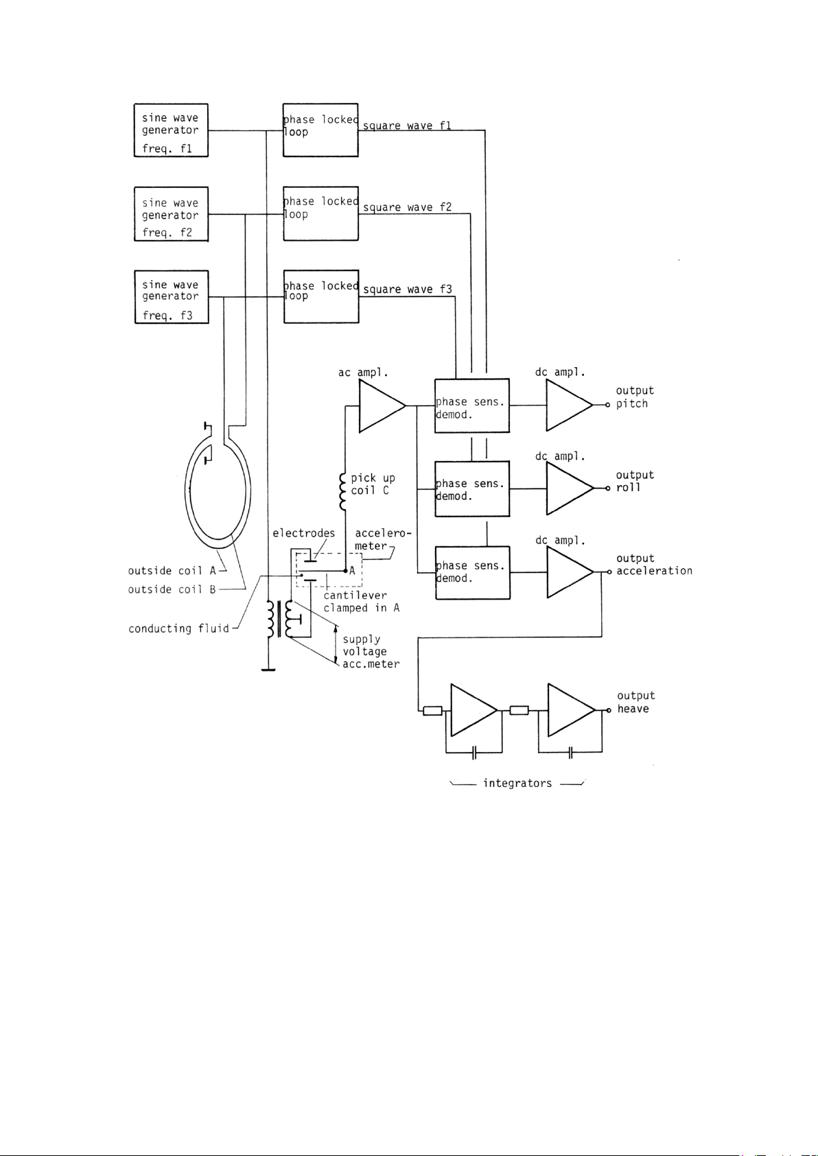
2 Principle of operation
Acceleration measurement 2.1
The deflection of the tip of a clamped cantilever is a measure for the acceleration. (Vertical
acceleration since the accelerometer is mounted on a gravity stabilised platform).
The cantilever is placed in a fluid in which an electric field is present.
So the potential of the cantilever is a measure for this deflection.
No static friction is involved; the acceleration measurement is without hysteresis.
High pass filter for heave measurement 2.2
The heave is obtained by double integrating the acceleration.
Temporary offset of the platform caused by horizontal acceleration (varying ship's speed) leads
to false acceleration outputs; in order to minimise the resulting false heave outputs a high pass
filter is used.
The remaining false output caused by a 180° reversal of ship's direction is proportional to the
square of the ship's speed, and amounts to approx.0.15 m at ship's speed of 1 m/sec.
The resulting transfer of high pass filter is:
Resulting amplitude transfer and phase shift is given under the specifications for some
frequencies.
6
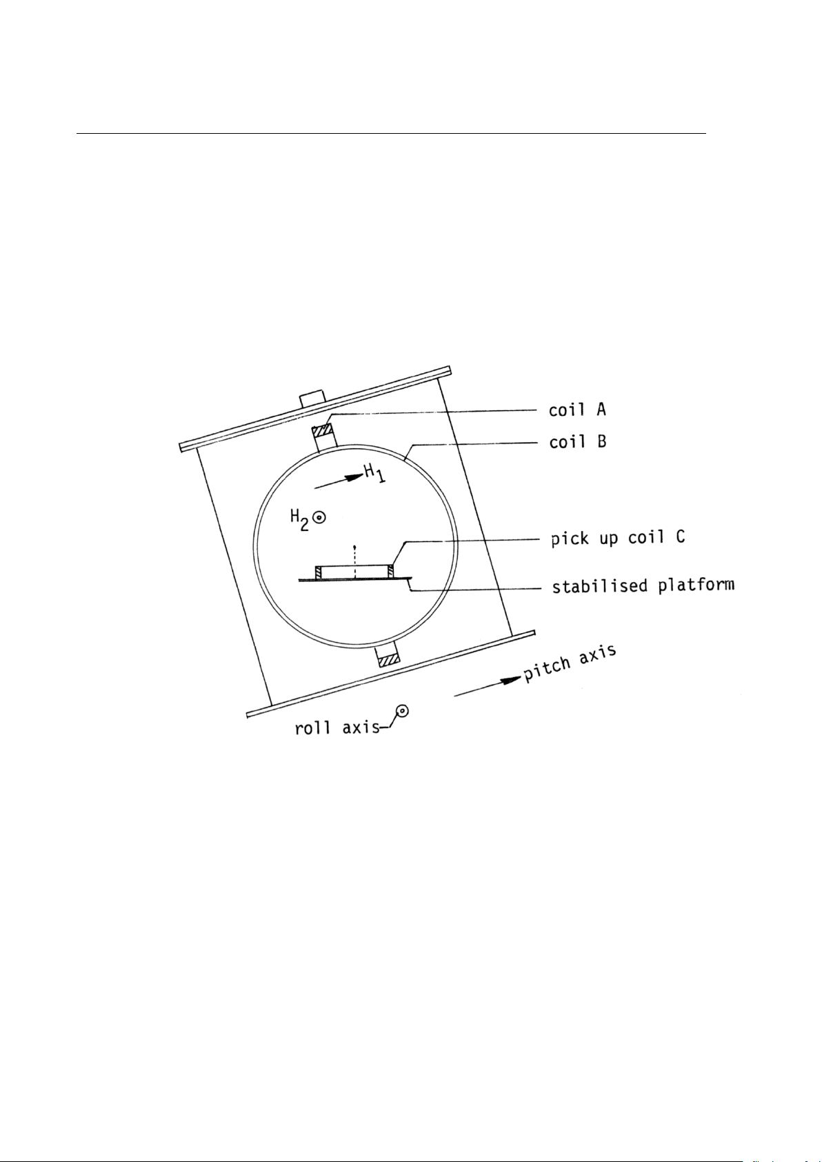
Pitch-roll measurement 2.3
An alternating magnetic field H1 is generated parallel to pitch axis and another field H2 at
different frequency parallel to roll axis (by means of coils A and B, fixed to housing and
perpendicular to each other).
A pickup coil C, mounted on the stabilised platform (horizontal plane) measures the vertical
components of H1 and H2 (fig. 2 and 3).
The induced voltage in coil C is amplified, phase sensitive demodulated and amplified again.
The pickup coil is placed in series with the output of the accelerometer.
See block diagram fig. 1.
fig. 2
7
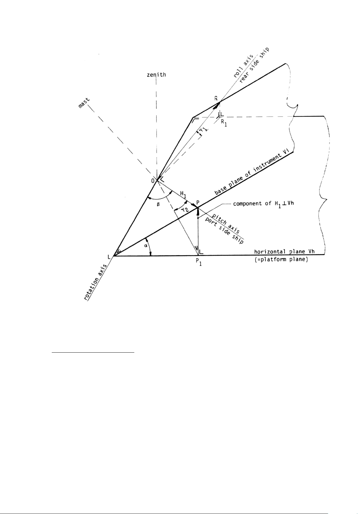
fig. 3
Calculation of induced voltage
Vi is base plane of instrument
Vh is horizontal plane (platform plane)
OL intersection of both planes
Angle between both planes is α
Be H1 = P the magnetic field vector generated parallel to the pitch axis.
OP1 the projection of OP on horizontal plane.
Component of H1 perpendicular to Vh = PP
1
So induced voltage in pickup coil on platform plane = ei;
ei = PP1/OP = sin ∠POP1 (roll output)
also is PP1/OP = PP1/PL . PL/OP = sinαsinβ
8

So roll output r = sin∠POP1 = sinαsinβ
Also pitch output p = sin∠ROR1 = sinαcosβ
For scale factor see specifications (8.2).
α = angle between instrument plane and horizontal plane
β = angle between pitch axis and rotation axis
∠POP1 = angle between pitch axis and horizontal plane
∠ROR1 = angle between roll axis and horizontal plane
9

3 Connections
+ junction box terminal no. 1
Supply
− junction box terminal no. 2
pitch junction box terminal no. 3
roll junction box terminal no. 4
Outputs heave junction box terminal no. 5
acceleration junction box terminal no. 6
common junction box terminal no. 7
For cable diameters see fig. 10.
10

4 Position
Pitch and roll axis are indicated by V formed cuttings in the rim of the bottom flange.
Mount the instrument with arrow (on text plate on lid) in the direction of the bow of the ship
(see fig. 10).
V formed cuttings in lid and top flange should coincide.
11
 Loading...