

Datawell 45100 User Manual
Datawell Waverider
Receiver
Manual
RX-D type 2
from serial no.: 45100
October 14, 2015
Service & Sales
Voltastr aat 3
1704 RP Heerhugowaard
The Neth erlands
+31 72 534 5298
+31 72 572 6406
www.datawell. nl
2
Check if mains supply matches with the specifications of the device.

3
Contents
1 Introduction ................................................................................................... 5
2 Front- and back-panel layout ....................................................................... 7
3 Installation ..................................................................................................... 9
3.1 Power supply ............................................................................................ 9
3.2 Receiving antenna ................................................................................... 9
3.3 Connecting the serial output to a PC ...................................................... 10
3.4 Grounding .............................................................................................. 10
3.5 Lightning protection ................................................................................ 11
4 Operation ..................................................................................................... 13
4.1 Receiving data ....................................................................................... 13
4.1.1 GPS position ................................................................................... 14
4.1.2 Signal quality ................................................................................... 14
4.1.3 Speaker........................................................................................... 14
4.2 Checking the receiver alignment ............................................................ 14
4.2.1 Realignment procedure ................................................................... 15
4.3 Changing the reception frequency ......................................................... 16
4.3.1 Crystal exchange procedure ........................................................... 16
4.4 W@ves21 and SeaSaw21 ..................................................................... 16
5 Troubleshooting .......................................................................................... 17
5.1 Power and fuses .................................................................................... 17
5.2 Antenna, signal quality and noise ........................................................... 17
5.3 Data interface ......................................................................................... 18
6 Specifications .............................................................................................. 19
7 Contact information .................................................................................... 21
Appendix A: Buoy HF data link and range ................................................... 22
Appendix B: Output message format ........................................................... 31
Appendix C: WAREC compatibility considerations .................................... 32
Appendix D: Abbreviations ........................................................................... 33
Appendix E: Receiving antennas .................................................................. 34

4

5
1 Introduction
The RX-D type 2 (RX-D2) is a HF link receiver that can receive all current Datawell Waverider
buoys with a standard (FSK) HF link transmitter.
The RX-D2 is tuned to the reception frequency using exchangeable receiving crystals. The RXD2 is connected to a PC running W@ves21 using RS232.
In Chapters 2,3 and 4 of this manual the installation and operation of the RX-D2 are discussed.
Chapter 5 gives some solutions to common problems while Chapter 6 discusses the
specifications of the RX-D2.

6
7
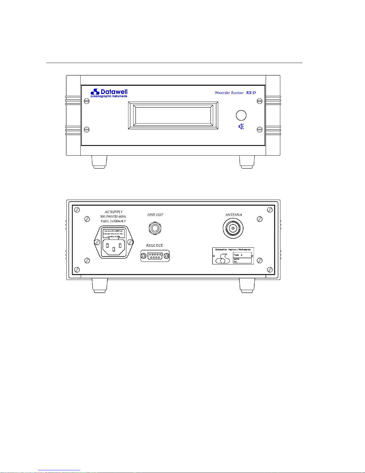
2 Front- and back-panel layout
The front panel contains the LCD and the speaker / test button.
The back panel contains the following connectors:
Socket for mains supply with fuses.
Audio out for beat-note monitoring.
Female 9-pin RS232 connector.
Antenna input connector.

8

9
3 Installation
This chapter describes how to install the RX-D2. To function correctly, an RX-D2 needs at least
the following:
Power supply.
Receiving antenna.
Connection to a PC using the serial port.
The following paragraphs will discuss these connections as well as grounding and lightning
protection considerations.
3.1 Power supply
The RX-D2 is fed from an AC power source with a voltage between 100 and 240 V. Please
refer to paragraph 6 for the exact voltage and power requirements.
The customer should provide for a cord set terminated with connector type C13 according to
IEC 60320-1 and a mains plug in accordance with national standards. The RX-C is a class I
appliance and requires an earthed socket for connection to protective-earth.
3.2 Receiving antenna
General HF link considerations
Directional Waverider buoys use a low power HF transmitter. The transmitting antenna is a
vertically polarized quarter wavelength whip. The receiving end of the link should receive as
much signal from the buoy transmitter and as little noise and interference as possible. To
achieve this the receiving antenna and -station should preferably be located at or near the coast,
see Appendix A and Appendix E for more information.
Receiving antenna location and height
The transmitter antenna is vertically polarised, therefore the receiving antenna must also be
mounted vertically. For the assembly of the antenna and adjustment of its length to the transmit
frequency see Appendix E.
Over sea the fieldstrength does not vary significantly with the height of the receiving antenna up
to 100 m. If the receiving antenna can be located within a few tens of meters of the sea, its
height is not important.
Over land the fieldstrength is attenuated by RF losses in the ground. For this reason it is
recommended that the antenna should be placed within a few tens of meters of the sea if
possible. If the distance from the sea is greater, the ground losses can (partially) be compensated
for by mounting the antenna at an height up to 20-30 meters. Generally, more than 20 -30m
above sea level will not improve the reception quality.
If possible mount the antenna in such a way that it has a free “sight” in the direction of the buoy.
Large structures such as embankments, ships and buildings in the direct optical path to the buoy
will attenuate the received signal.
For interference free reception it is advisable to install the Receiving antenna as far as possible
from local interference sources such as combustion engines, electric motors and fluorescent
lamps. In general a transmitting distance of 50 Km (30 n.m.) over sea water can be attained
when the receiving antenna is located at least 100 m from interference sources mentioned. If

10
considerable interference is present at the location where the receiving equipment has to be
installed, the antenna should be moved to a position with lower interference. Also the use of a
directional antenna (see Appendix E) can be considered. Transmission range of the DWR-G
0.4m is less: line of sight with a handheld receiving antenna and 25 Km with a ground plane
antenna.
Installing the antenna cable
The length of the antenna cable is not critical as long as a good quality coaxial cable is used.
The supplied RG 213 cable has an attenuation of 3.5 dB/100m allowing up to 200m of cable
lengths. However, shorter cable lengths are always preferred to improve the signal to noise
ratio. Especially in signal limited situations (where signals of buoys at the edge of the normal
range must be received) the cable should be no longer than strictly necessary. Install the coaxial
cable without stretching or bending and avoid mechanical stress. With respect to routing there
are few restrictions. Although the cable is screened and not very sensitive to surrounding
electric or magnetic fields and disturbances, try to avoid routing the cable directly along power
cabling.
Be aware of the fact that reception in most areas is limited by local noise and interference. It
pays to install the antenna in such a way that distance to local sources of noise and interference
is maximized. In these situations, it is entirely acceptable to use a longer cable in order to install
the antenna further away from a source of interference.
Using a directional antenna
In case of weak signal and/or high local noise or interference the use of a directional antenna
can be considered. The sensitivity of such an antenna is 3 dB higher in the direction of the buoy.
Interference and noise generated at the landside will be attenuated by 6 dB. The combination of
gain at the frontside (thus towards the buoy) and suppression of noise from the backside of the
antenna will improve the signal to noise ratio.
Using an antenna splitter
For connecting multiple receivers to a single antenna, the Datawell Antenna Splitter can be
used. This device is optimized for the buoy reception frequencies and signal levels. With the
Datawell Antenna Splitter up to six receivers can be used with a single antenna.
3.3 Connecting the serial output to a PC
Connection of the serial output to a PC is done using a standard D-SUB RS232 cable assembly.
The receiver has a nine pin D-SUB outlet of which only pins 2 and 3 carry active signals. Pin 5
is signal ground. Normal RS232 cable length restrictions apply. RS232 ports are becoming
scarce on PC’s, in favour of USB ports. This problem may be solved with a RS232-USB serial
adapter. However, some adapter models do not offer the same data transmission reliability as
RS232 serial connections do.
3.4 Grounding
For correct reception of buoy signals grounding of the antenna is not necessary. The supplied
ground plane antenna takes care of its own RF reference. Also grounding of the receiver and/or
connected computer is not a remedy for all kind of noises and disturbances. Noise and trouble
free reception should be possible without any connection or reference to ground.
However from a viewpoint of safety it is recommended to connect the receiver to a safety
ground. Normally the three wire power cord will take care of this.

11
3.5 Lightning protection
For effective protection against lightning strike it is advisable to connect the antenna supporting
structure to a ground electrode that is suitable for lightning protection. In the case that the
building or adjoining buildings and/or mast on which the antenna is installed is already lightning
protected it is sufficient to connect the antenna supporting structure to this grounding net. Also
the antenna cable should be protected with an impulse suppressor at the point where the antenna
cable enters the building. This impulse suppressor should be grounded properly. When in doubt
leave lightning protection to skilled consultants and/or companies.

12
 Loading...