

Datawave R02 User Manual

Wireless Bridge Analog & Digital
I/O
USERS MANUAL
R02

Contents
Overview ....................................................................................................................................................... 3
Specifications ................................................................................................................................................ 3
Absolute Maximum Ratings ...................................................................................................................... 3
Recommended Operating Conditions ...................................................................................................... 3
Performance ............................................................................................................................................. 4
Power Requirements ................................................................................................................................ 4
Mechanical ................................................................................................................................................ 5
Pinout and Wiring ..................................................................................................................................... 5
Operation ...................................................................................................................................................... 6
Standard Operation .................................................................................................................................. 6
LED Indication ....................................................................................................................................... 7
Data Formats and Baud Rates ............................................................................................................... 7
Communicating with the Wireless Bridge .................................................................................................... 8
Common Configurations and Use Cases ..................................................................................................... 10
Analog Signal Bridge ............................................................................................................................... 10
Digital Signal Bridge ................................................................................................................................ 12
Wireless Data Collector ........................................................................................................................... 12
ADIO Command Reference Table ........................................................................................................... 14
Changing the Baud Rate .......................................................................................................................... 16
Configuring the XBee Module ................................................................................................................. 17
Antennas ..................................................................................................................................................... 18
Part Numbers and Compatibility ................................................................................................................ 18
Certifications ............................................................................................................................................... 19
ADIO WIRELESS BRIDGE USER’S MANAUL REV. 02 2
Overview
The ADIO Wireless Bridge is configurable Analog or Digital input and output wireless transmission
device. It is designed measure and replicate Analog or Digital I/O signals and wirelessly transmit those
signals to a second ADIO Wireless Bridge device. Alternatively, it can be used in conjunction with the RS232, RS-485 or USB Wireless Bridges to measure and transmit data back to a serial host device. In this
mode it can act as a medium to be a wireless data logger.
The ADIO Wireless Bridge has a five pin screw terminal block for the four channels and a micro USB port
for radio and device configuration specific to the ADIO Wireless Bridge. Data is also available on the
micro USB port. By default, the ADIO Wireless Bridge is configured to measure up to four 0-10V Analog
inputs. Inputs can also be configured for Digital inputs (3.3V and 5V tolerant) or for 4-20mA inputs. The
four channels can also be configured as 0-10V Analog outputs or as Digital signal outputs.
Specifications
Absolute Maximum Ratings
MIN MAX UNIT
VDC Supply Voltage 6.5 36 V
VI Input Voltage on any I/O -0.3 10.5 V
IO Output Current 1 mA
IIN 4-20mA Input current 0 21 mA
Recommended Operating Conditions
MIN MAX UNIT
VDC Supply Voltage 7 30 V
V
Digital High-level input voltage V 2.1 V
IH
VIL Digital Low-level input voltage V 0.8 V
IIN Current Loop input 0 20 mA
A
Analog input voltage range 0 10.1 V
IN
Accuracy Input to Output accuracy over temperature 0.50 %
Tsample Signal Sample rate 30 min 50ms
ADIO WIRELESS BRIDGE USER’S MANAUL REV. 02 3

Performance
OVER
-
THE-AIR
250 Kbps
250 Kbp
s Low: 10Kbps
INDOOR/URBAN
Up to 200ft.
Up to 300ft.
Up to 1000ft.
OUTDOOR/ RF LINE
-
Up to 4000ft.
Up to 2 miles
Up to 10 miles
TRANSMIT POWER
6.3 mW
63 mW
1 Watt
RECEIVE SENSITIVITY
-101 dBm
-101 dBm
Low:
-
113 dBm
INPUT VOLTAGE
7-
30VDC
7-
30VDC
7-
30VDC
TRANSMIT CURRENT
12mA @ 12V
40mA @ 12V
270mA @ 12V
RECEIVE CURRENT
12mA @ 12V
12mA @ 12V
17mA @ 12V
24LP 24HP 09SX
DATA RATE
RANGE
OF-SITE RANGE
Power Requirements
Mid: 110Kbps
High: 250Kbps
Mid: -106 dBm
High: -103 dBm
Table 1. General Performance Specifications
24LP 24HP 09SX
Table 2. Power Requirements
ADIO WIRELESS BRIDGE USER’S MANAUL REV. 02 4
Mechanical
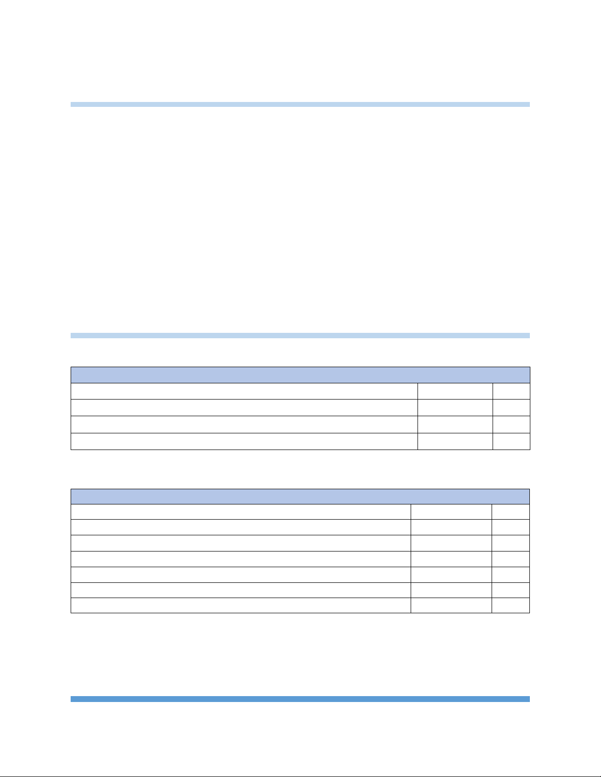
Fig. 1 Mechanical Dimensions
The mechanical dimensions for the Wireless Bridge are shown in Figure 1. The mechanical dimensions
are shown with the optional DIN rail mount bracket which is not included with the standard part
number. Mechanical data for the antenna is not shown.
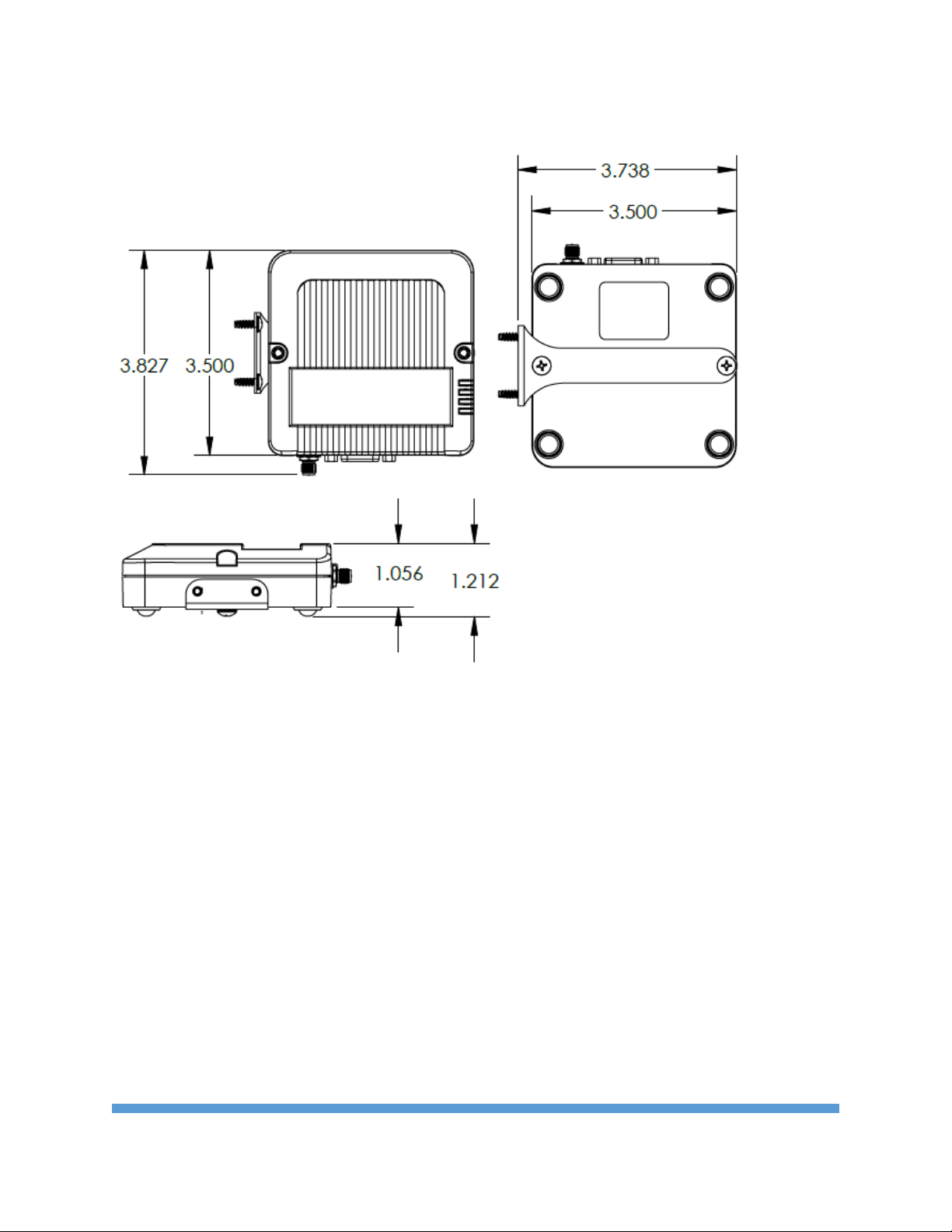
Pinout and Wiring
The uses a five pin screw terminal for I/O signals. Pin 5 is ground. Figures 2 & 3 show the connectors and
pinout for the ADIO Wireless Bridge.
ADIO WIRELESS BRIDGE USER’S MANAUL REV. 02 5
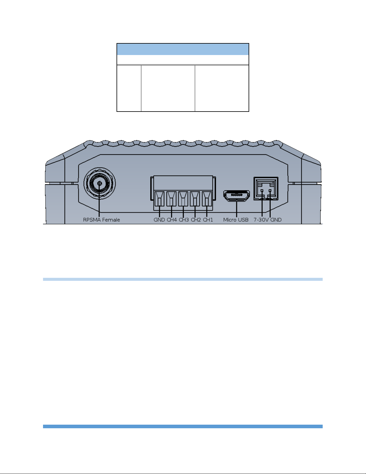
SCREW TERMINAL ADIO PINOUT
PIN Name Direction
1 Channel 1 Default Input
2 Channel 2 Default Input
3 Channel 3 Default Input
4 Channel 4 Default Input
5 Ground (GND) Signal Ground
Fig 2. Screw Terminal Pinout
Fig 3. Wireless Bridge Connectors and Pins
Operation
Standard Operation
The ADIO Wireless Bridge is intended to measure Analog or Digital Input data lines and wirelessly
transmit those signal levels to a second ADIO Wireless Bridge to output the measured signal levels. By
default, any data sent into one device is broadcast and received by all other Wireless Bridge devices
within range. The ADIO uses channel tokens to control which devices respond to the data. Additional
addressing can be used to isolate communication between specific devices or to create unique
networks.
The Wireless Bridge device is equipped with a micro USB connector. When the micro USB connector is
plugged into a USB host device such as a computer, the Wireless Bridge enumerates as two standard
serial COM ports. One port is a data port and can send and receive data. The second COM port is the
device’s information port.
The Wireless Bridge uses standard composite device drivers are preinstalled in Windows 10 and MAC
computers. Drivers will need to be installed for Windows 7 machines. While not every machine will
ADIO WIRELESS BRIDGE USER’S MANAUL REV. 02 6
 Loading...