

Datawave 24HP, 09SX, 24LP User Manual

RS-232 Wireless Bridge
USERS MANUAL
R02

Contents
Overview ....................................................................................................................................................... 3
Specifications ................................................................................................................................................ 3
Performance ............................................................................................................................................. 3
Power Requirements ................................................................................................................................ 4
Mechanical ................................................................................................................................................ 4
Pinout and Wiring ..................................................................................................................................... 5
Operation ...................................................................................................................................................... 6
Standard Operation .................................................................................................................................. 6
LED Indication ....................................................................................................................................... 6
Data Formats and Baud Rates ............................................................................................................... 7
Common Configurations and Use Cases ....................................................................................................... 7
Radio Architectures ................................................................................................................................... 7
Point-to Point ........................................................................................................................................ 7
Point-to-Multipoint ............................................................................................................................... 8
Communicating with the Wireless Bridge .................................................................................................... 9
RS-232 Command Reference Table ........................................................................................................ 10
Changing the Baud Rate .......................................................................................................................... 11
Configuring the XBee Module ................................................................................................................. 13
Antennas ..................................................................................................................................................... 14
Part Numbers and Compatibility ................................................................................................................ 14
Certifications ............................................................................................................................................... 15
RS-232 WIRELESS BRIDGE USER’S MANAUL REV. 02 2

Overview
OVER
-
THE-AIR
250 Kbps
250 Kbps
Low: 10Kbps
INDOOR/URBAN
Up to 200ft.
Up to 300ft.
Up to 1000ft.
OUTDOOR/ RF LINE
-
Up to 4000ft.
Up to 2 miles
Up to
10 miles
TRANSMIT POWER
6.3 mW
63 mW
1 Watt
RECEIVE SENSITIVITY
-101 dBm
-101 dBm
Low:
-
113 dBm
The RS-232 wireless bridge is designed to be a transparent bidirectional three-wire RS-232 cable
replacement. The RS-232 Wireless Bridge has a DB9 DCE female connector for data and for the internal
radio module configuration, and a micro USB port to configure settings that are specific to the RS-232
Wireless Bridge. The RS-232 Wireless Bridge is available in three different options differing by frequency
and RF power output.
It is possible to mix and match Wireless Bridge products. The RS-232 Wireless Bridge will communicate
with the RS-485, Analog and Digital I/O and USB Wireless Bridge products that share the same radio
configuration. By using an RS-485 Wireless Bridge at point A and a RS-232 Wireless Bridge at point B, the
wireless bridges can act as a RS-485 to RS-232 over-the-air converter.
Specifications
Performance
24LP 24HP 09SX
DATA RATE
RANGE
OF-SITE RANGE
Table 1. General Performance Specifications
Mid: 110Kbps
High: 250Kbps
Mid: -106 dBm
High: -103 dBm
RS-232 WIRELESS BRIDGE USER’S MANAUL REV. 02 3
INPUT VOLTAGE
7-
30VDC
7-
30VDC
7-
30VDC
TRANSMIT CURRENT
12mA @ 12V
40mA @ 12V
270mA @ 12V
RECEIVE CURRENT
12mA @ 12V
12mA @ 12V
17mA @ 12V
Power Requirements
24LP 24HP 09SX
Table 2. Power Requirements
Mechanical
RS-232 WIRELESS BRIDGE USER’S MANAUL REV. 02 4
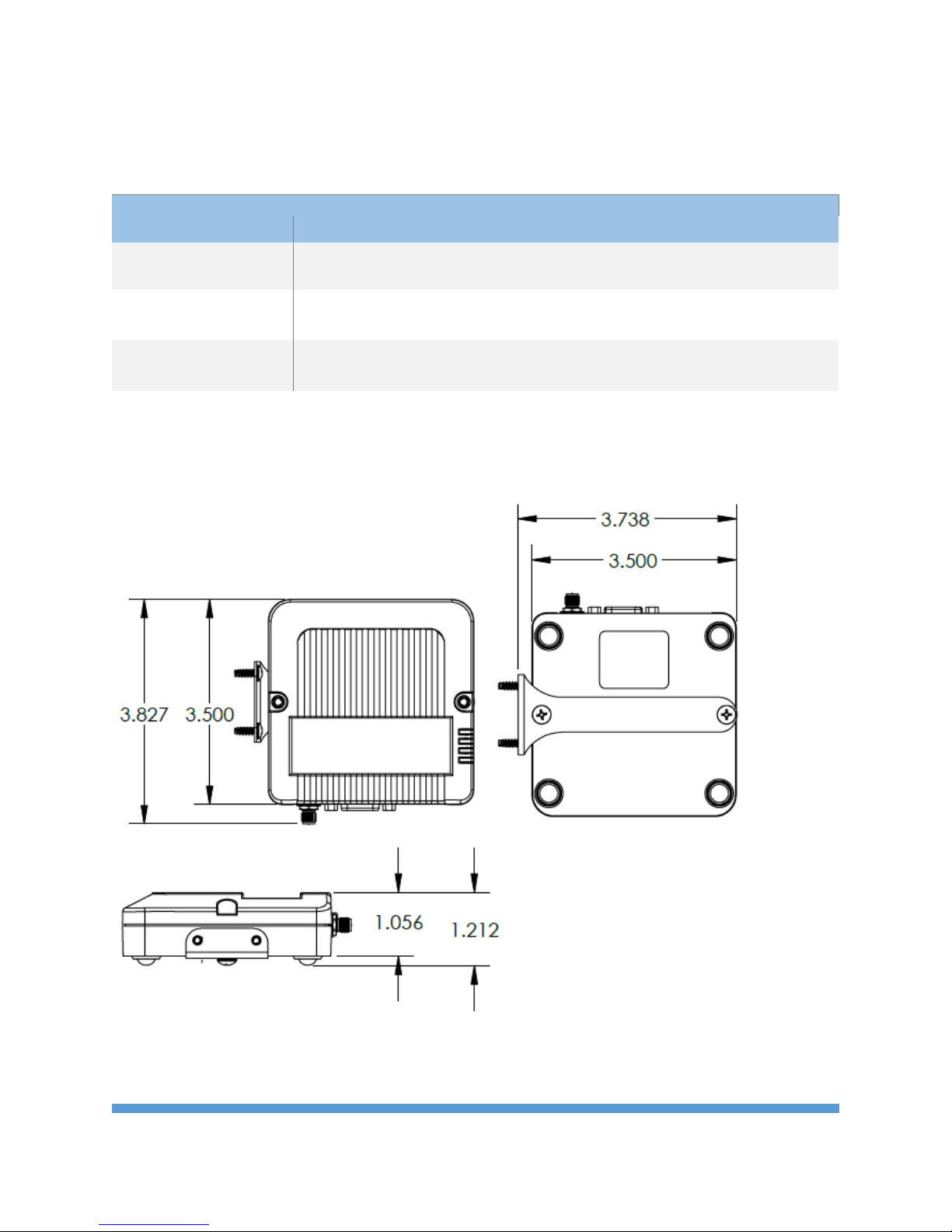
Fig. 1 Mechanical Dimensions
The mechanical dimensions for the Wireless Bridge are shown in Figure 1. The mechanical dimensions
are shown with the optional DIN rail mount bracket which is not included with the standard part
number. Mechanical data for the antenna is not shown.
Pinout and Wiring
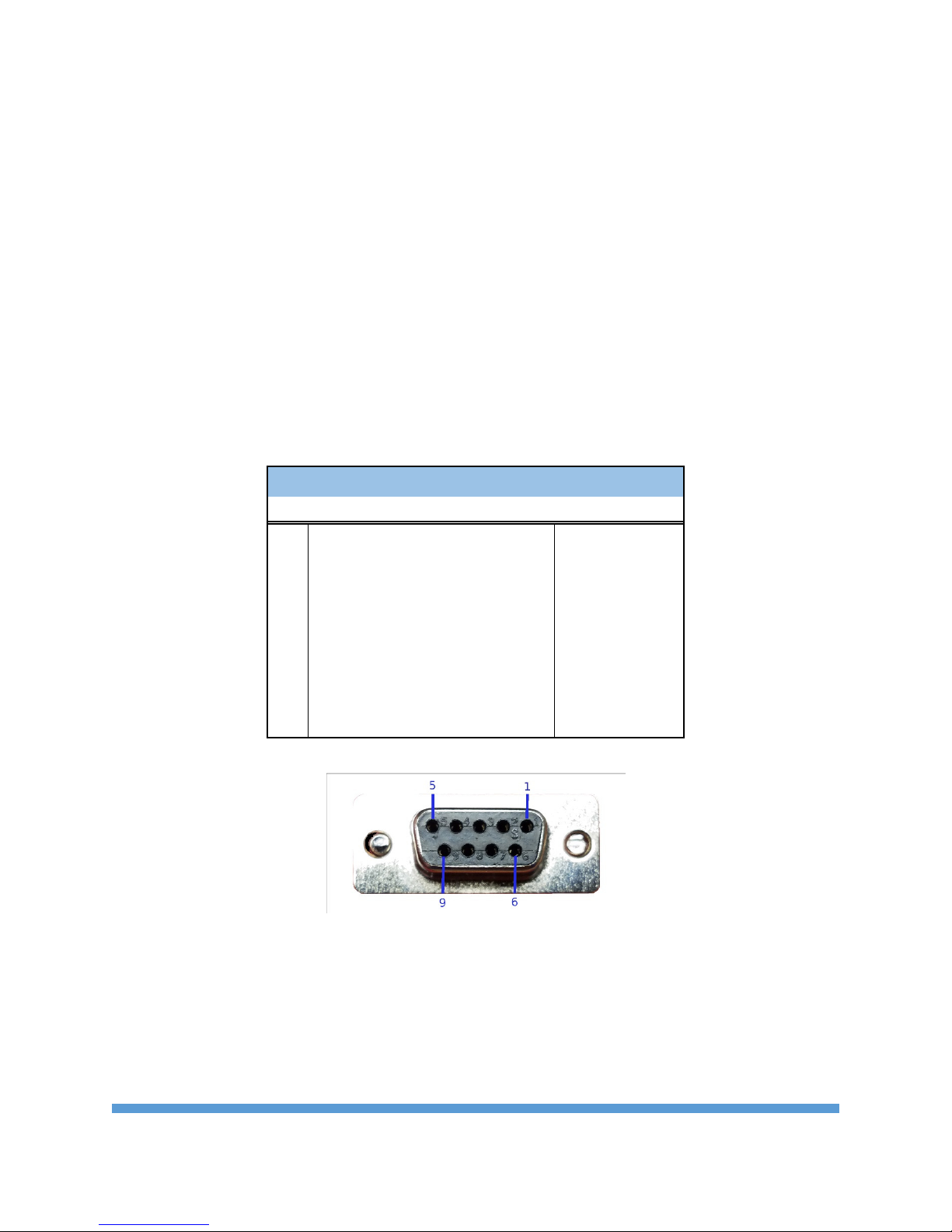
The pinout follows the standard RS-232 Data Communications Equipment (DCE) device. Signal names
for RS-232 are defined from the standpoint of a Data Terminal Equipment (DTE) device. The signal
named Receive Data is an output from the RS-232 Wireless Bridge and the signal named Transmit Data is
an input. Not all RS-232 signals are implemented on the Wireless Bridge. Only Transmit Data, Received
Data and Ground are required for basic function. The DTR input may be used to control the pin sleep
function on the internal radio for reduced power draw.
Wireless Bridge DB9 RS232 DCE Pinout
PIN
1 Carrier Detect (DCD) Not Used
2 Receive Data (RD) Output
3 Transmit Data (TD) Input
4 Data Terminal Ready (DTR) Input
5 Ground (GND) Signal Ground
6 Data Set Ready (DSR) Not Used
7 Request to Send (RTS) Not Used
8 Clear to Send (CTS) Not Used
9 Ring Indicator (RI) Not Used
Name Direction
RS-232 WIRELESS BRIDGE USER’S MANAUL REV. 02 5
Fig 2. DB9 Pinout
 Loading...