

Datavideo TVS-2000A Instruction Manual
TVS-2000A
TRACKING VIRTUAL
STUDIO SYSTEM
Instruction manual
VIRTUAL STUDIO SYSTEM
TVS-2000A

2
Table of Contents
FCC COMPLIANCE STATEMENT ..................................................................................................... 4
WARNINGS AND PRECAUTIONS .................................................................................................. 4
WARRANTY ................................................................................................................................... 5
STANDARD WARRANTY .................................................................................................................... 5
THREE YEAR WARRANTY .................................................................................................................. 5
DISPOSAL ...................................................................................................................................... 5
CHAPTER 1 OVERVIEW .............................................................................................................. 6
1.1 FEATURES ............................................................................................................................ 6
CHAPTER 2 TVS-2000A TRACKING VIRTUAL STUDIO SETUP .................................................... 8
2.1 SYSTEM REQUIREMENT .......................................................................................................... 8
2.2 CONNECTIONS ...................................................................................................................... 8
Front Panel ............................................................................................................................. 8
Back Panel .............................................................................................................................. 8
Input/Output Card Options..................................................................................................... 9
2.3 REMOVABLE HARD DISK INSTA L L AT I ON .................................................................................... 10
2.4 SYSTEM DIAGRAM ............................................................................................................... 11
2.5 RMC-280 REMOTE CONTROLLER .......................................................................................... 12
Control Panel Overview ........................................................................................................ 13
Main Unit - Rear Panel ......................................................................................................... 14
Program and Preset rows ..................................................................................................... 14
Preview and Program Switching ........................................................................................... 14
Downstream Keyers .............................................................................................................. 15
Function Keys ........................................................................................................................ 15
PTZ Camera Control .............................................................................................................. 16
Keyboard Backlight ............................................................................................................... 18
2.6 HOW TO CALIBRATE THE PTC-150 CAMERA POSITION FOR YOUR TVS-2000A SYSTEM ................... 18
CHAPTER 3 STARTING TVS-2000A SOFTWARE ........................................................................ 23
3.1 PRODUCTION LIVE ............................................................................................................... 24
3.2 STILL TEXT EDIT .................................................................................................................. 24
3.3 TVS NEWS LINK.................................................................................................................. 24
3.4 VIRTUALSET SHOP ........................................................................................................... 24
3.5 SHUTDOWN ....................................................................................................................... 24
3.6 CONFIGURATION ................................................................................................................. 25
CHAPTER 4 PRODUCTION LIVE SCREEN .................................................................................. 26
4.1 TOOL BAR ......................................................................................................................... 26
File ........................................................................................................................................ 26
Options ................................................................................................................................. 26
Help ...................................................................................................................................... 28
4.2 MULTI-VIEW AREA .............................................................................................................. 28
4.3 PROGRAM AND PREVIEW ROWS & FUNCTION SETTINGS ............................................................. 29
11-input Main Switcher ........................................................................................................ 30
Switching between Preview and Program Views ................................................................. 30
Downstream Keys ................................................................................................................. 30
4.4 SCENE EDITING ................................................................................................................... 32

3
4.4.1 Camera Setup .......................................................................................................... 33
4.4.2 Linear and Curved Auto Play ................................................................................... 35
4.5 FILE MANAGEMENT ............................................................................................................ 36
4.6 TRIGGERS – RMC-280 FUNCTION KEYS ................................................................................. 39
Advanced .............................................................................................................................. 40
Simple ................................................................................................................................... 41
4.7 MONITOR CONFIGURATION ................................................................................................... 41
4.8 GENERAL DIS P L AY A N D AUDIO SETTINGS ................................................................................. 42
4.9 MOTION CAPTURE SPECIFICATION .......................................................................................... 45
4.10 PROGRAM VIDEO STREAM .................................................................................................... 46
4.11 TRACKING CAMERAS ............................................................................................................ 47
CHAPTER 5 CHROMA AND LUMA KEYS ................................................................................... 48
5.1 KEY SELECTION ................................................................................................................... 48
5.2 CHROMA KEY ..................................................................................................................... 48
5.3 MATTE CONTROL ................................................................................................................ 49
5.4 TOLERANCE CORRECTION...................................................................................................... 51
5.5 SPILL CORRECTION .............................................................................................................. 53
5.6 EDGE CORRECTION .............................................................................................................. 55
5.7 GARBAGE MASK ................................................................................................................. 55
5.8 POST CORRECTION .............................................................................................................. 57
CHAPTER 6 FAST CHROMAKEYING .......................................................................................... 58
6.1 SIMPLE CHROMA KEY .......................................................................................................... 58
6.2 WIZARD ............................................................................................................................ 58
CHAPTER 7 3D STUDIO EDITOR ............................................................................................... 59
7.1 OPEN THE 3D STUDIO EDITOR ............................................................................................... 59
7.2 STUDIO EDITOR OVERVIEW ................................................................................................... 59
Virtual Camera Customization Tool ...................................................................................... 60
View of the Scene ................................................................................................................. 60
Virtual Set Object Selection .................................................................................................. 61
7.3 STUDIO 3D EDITOR WIZARD ................................................................................................. 65
How to add an accessory object? ......................................................................................... 69
How to change the position of an accessory object? ........................................................... 69
CHAPTER 8 SOUND MIXER ...................................................................................................... 71
CHAPTER 9 SPECIFICATIONS .................................................................................................... 72
SERVICE & SUPPORT ................................................................................................................... 73
Disclaimer of Product and Services
The information offered in this instruction manual is intended as a guide only. At all times,
Datavideo Technologies will try to give correct, complete and suitable information. However,
Datavideo Technologies cannot exclude that some information in this manual, from time to
time, may not be correct or may be incomplete. This manual may contain typing errors,
omissions or incorrect information. Datavideo Technologies always recommend that you
double check the information in this document for accuracy before making any purchase
decision or using the product. Datavideo Technologies is not responsible for any omissions or
errors, or for any subsequent loss or damage caused by using the information contained
within this manual. Further advice on the content of this manual or on the product can be
obtained by contacting your local Datavideo Office or dealer.

4
FCC Compliance Statement
This device complies with part 15 of the FCC rules. Operation is subject to the following two
conditions:
1) This device may not cause harmful interference, and
2) This device must accept any interference received, including interference that may cause
undesired operation.
Warnings and Precautions
1. Read all of these warnings and save them for later reference.
2. Follow all warnings and instructions marked on this unit.
3. Unplug this unit from the wall outlet before cleaning. Do not use liquid or
aerosol cleaners. Use a damp cloth for cleaning.
4. Do not use this unit in or near water.
5. Do not place this unit on an unstable cart, stand, or table. The unit may fall, causing
serious damage.
6. Slots and openings on the cabinet top, back, and bottom are provided for ventilation. To
ensure safe and reliable operation of this unit, and to protect it from overheating, do not
block or cover these openings. Do not place this unit on a bed, sofa, rug, or similar surface,
as the ventilation openings on the bottom of the cabinet will be blocked. This unit should
never be placed near or over a heat register or radiator. This unit should not be placed in a
built-in installation unless proper ventilation is provided.
7. This product should only be operated from the type of power source indicated on the
marking label of the AC adapter. If you are not sure of the type of power available, consult
your Datavideo dealer or your local power company.
8. Do not allow anything to rest on the power cord. Do not locate this unit where the power
cord will be walked on, rolled over, or otherwise stressed.
9. If an extension cord must be used with this unit, make sure that the total of the ampere
ratings on the products plugged into the extension cord do not exceed the extension cord
rating.
10. Make sure that the total amperes of all the units that are plugged into a single wall outlet
do not exceed 15 amperes.
11. Never push objects of any kind into this unit through the cabinet ventilation slots, as they
may touch dangerous voltage points or short out parts that could result in risk of fire or
electric shock. Never spill liquid of any kind onto or into this unit.
12. Except as specifically explained elsewhere in this manual, do not attempt to service this
product yourself. Opening or removing covers that are marked “Do Not Remove” may
expose you to dangerous voltage points or other risks, and will void your warranty. Refer
all service issues to qualified service personnel.
13. Unplug this product from the wall outlet and refer to qualified service personnel under the
following conditions:
a. When the power cord is damaged or frayed;
b. When liquid has spilled into the unit;
c. When the product has been exposed to rain or water;
d. When the product does not operate normally under normal operating conditions.
Adjust only those controls that are covered by the operating instructions in this
manual; improper adjustment of other controls may result in damage to the unit and
may often require extensive work by a qualified technician to restore the unit to
normal operation;
e. When the product has been dropped or the cabinet has been damaged;
f. When the product exhibits a distinct change in performance, indicating a need for
service.

5
Warranty
Standard Warranty
• Datavideo equipment are guaranteed against any manufacturing defects for one year from
the date of purchase.
• The original purchase invoice or other documentary evidence should be supplied at the
time of any request for repair under warranty.
• The product warranty period begins on the purchase date. If the purchase date is
unknown, the product warranty period begins on the thirtieth day after shipment from a
Datavideo office.
• Damage caused by accident, misuse, unauthorized repairs, sand, grit or water is not
covered under warranty.
• Viruses and malware infections on the computer systems are not covered under warranty.
• Any errors that are caused by unauthorized third-party software installations, which are
not required by our computer systems, are not covered under warranty.
• All mail or transportation costs including insurance are at the expense of the owner.
• All other claims of any nature are not covered.
• All accessories including headphones, cables, and batteries are not covered under
warranty.
• Warranty only valid in the country or region of purchase.
• Your statutory rights are not affected.
Three Year Warranty
• All Datavideo products purchased after July 1st, 2017 are qualified for
a free two years extension to the standard warranty, providing the
product is registered with Datavideo within 30 days of purchase.
• Certain parts with limited lifetime expectancy such as LCD panels,
DVD drives, Hard Drive, Solid State Drive, SD Card, USB Thumb Drive, Lighting, Camera
module, PCIe Card are covered for 1 year.
• The three-year warranty must be registered on Datavideo's official website or with your
local Datavideo office or one of its authorized distributors within 30 days of purchase.
Disposal
For EU Customers only - WEEE Marking
This symbol on the product or on its packaging indicates that this product
must not be disposed of with your other household waste. Instead, it is
your responsibility to dispose of your waste equipment by handing it over
to a designated collection point for the recycling of waste electrical and
electronic equipment. The separate collection and recycling of your waste
equipment at the time of disposal will help to conserve natural resources
and ensure that it is recycled in a manner that protects human health and the environment.
For more information about where you can drop off your waste equipment for recycling,
please contact your local city office, your household waste disposal service or the shop where
you purchased the product.
CE Marking is the symbol as shown on the left of this page. The letters
"CE" are the abbreviation of French phrase "Conformité Européene" which
literally means "European Conformity". The term initially used was "EC
Mark" and it was officially replaced by "CE Marking" in the Directive
93/68/EEC in 1993. "CE Marking" is now used in all EU official documents.

6
Chapter 1 Overview
The TVS-2000A is a computer-based 3D Tracking Virtual Studio System. It is a real-time
production system with very high quality live chromakeying.
The TVS-2000A uses two live cameras to create virtual cameras. This allows the director to
zoom, pan and tilt the camera virtually within the set.
Furthermore, with two camera inputs and two keyers, the TVS-2000A gives the user the
capability to place two talents on one virtualset. The TVS-2000A can also be used in a remote
scenario whereby the images captured by the two cameras at two different sites are placed
on one single virtualset.
Also Integrated into the system are tools to record the program output, broadcast live
program and stream video over the Internet.
1.1 Features
Varieties of System Inputs with Front Object Integration:
• Two Camera Inputs;
• One AUX input;
• Camera control card for connecting two tracking cameras;
• Media (videos) – two clips at the same time;
• Still images (bitmaps, text) – two at the same time;
• Text – two text compositions at the same time.
Additional Media Features
• A Media Bin is a simple-to-use interface that makes it possible to gather all the media
necessary for programme broadcast in one place;
• The media can be transferred from the bin to virtual players, used on air or as a source
in virtual studios;
• The system has five bin tabs for seven kinds of media: audio, videos, still images, and
text;
• Logo insertion on virtual scene.
Virtual Background Features
• Loads up to four virtual studio virtual cameras simultaneously;
• Configurable Pan/Tilt/Zoom;
• Multi-Point Zoom;
• Virtual Studio backgrounds, which can be downloaded from Datavideo’s virtual
background database website;
• 30 free built-in virtualsets in the system;
• CG-loaded backgrounds imported from external files, or edited by Still Text Editor.
Media Previews
• Camera preview (two at a time, depending on system configuration);
• Media preview (two at a time);
• Still image preview (two at a time);
• Text preview (two at a time);
• Up to four virtual studio previews;

7
• PREVIEW – presentation of the next element prepared for broadcast;
• PROGRAMME – presentation of the current programme broadcast (system output);
• Previews on multiple monitors (if monitors are connected to a workstation, it is
possible to obtain different preview configurations, even on three monitors).
Supported Formats
• Format: 1080p60 – image resolution: 1920 x 1080
• Format: 1080p59.94 – image resolution: 1920 x 1080
• Format: 1080p50 – image resolution: 1920 x 1080
• Format: 1080p30 – image resolution: 1920 x 1080
• Format: 1080p29.97 – image resolution: 1920 x 1080
• Format: 1080p25 – image resolution: 1920 x 1080
• Format: 1080i60 – image resolution: 1920 x 1080
• Format: 1080i59.94 – image resolution: 1920 x 1080
• Format: 1080i50 – image resolution: 1920 x 1080
• Format: 720p60 – image resolution: 1280 x 720
• Format: 720p59.94 – image resolution: 1280 x 720
• Format: 720p50 – image resolution: 1280 x 720
Video Processing Formats
• Video processing: 4:4:4 16-bit floating-point internal processing;
• Inputs and outputs: YUV 4:2:2;
• Capture in output format: 4:2:0;
• Streaming: 4:2:0.
Other Miscellaneous Features
• A Five-in-One System: Virtual Studio, Switcher, Character Generator, Recorder and
Web Streaming
• Multi-Language Support;
• RMC-280 Remote Control;
• Audio Embedding Capability;
• Real time streaming;
• Hard Drive (HD) Recording;
• 3D Studio Editor;
• Built-in TVS AUX Card for an additional input.
8
Chapter 2 TVS-2000A Tracking Virtual Studio Setup
2.1 System Requirement
Monitor x 1 (up to three monitors can be connected to choices of the HDMI x 2, DVI-D x
1, DisplayPort x 2)
Keyboard
2 x SDI cameras for trackless use or Datavideo PTC-150 cameras for tracking use
2.2 Connections
Front Panel
Access to the front panel is protected with a keyed door. This provides protection against the
system being accidentally switched off or reset or the data disk being removed.
It is recommended to position the workstation horizontally so as to ensure air flows reaching
the front and the back panels. Fans providing appropriate system cooling are located behind
the panels. The workstation case is designed to be mounted on a server rack and occupies a
4U space.
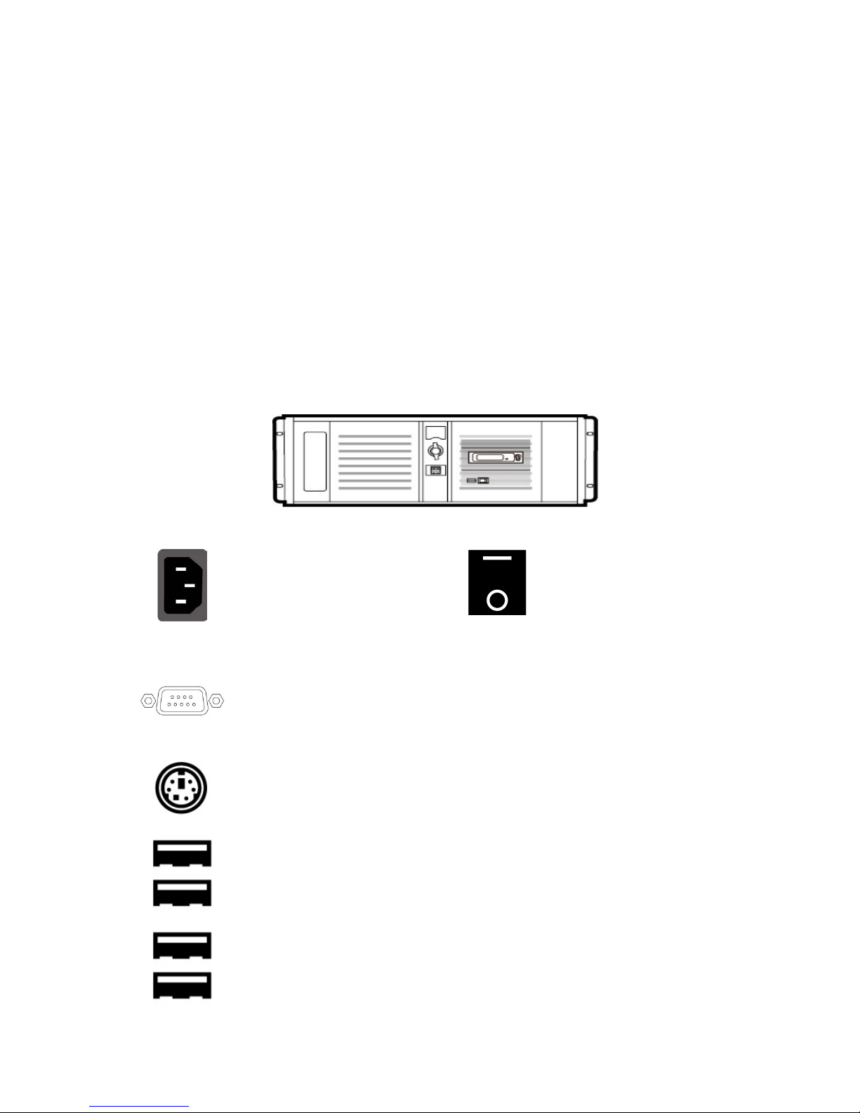
Back Panel
Power Supply Socket
Depending on the shipment
destination and the user
location, a power supply cord
with a suitable plug will be
supplied
Power On/Off Switch
Switches power On/Off
0 – OFF 1 – ON
RS-232 Connection
The rear panel contains the RS-232 connection for operation with an external
Datavideo RMC-280 control panel.
PS/2 Keyboard / Mouse Combo Port
USB 2.0 Ports
Connection of an external standard USB keyboard and mouse
USB 3.0 Ports
Connection of USB Wireless Dongle / Adapter IF ANY
Please note that if you do not find the USB wireless dongle in the box, the
TVS-2000A System Unit that you receive may already have a built-in
wireless network card.
9
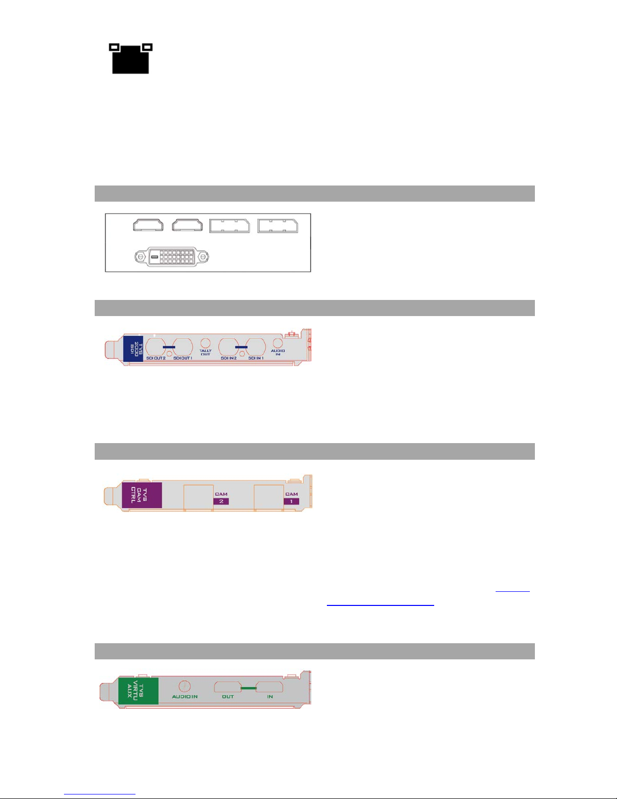
LAN (RJ-45) Port
Connection of the workstation to a computer network
Input/Output Card Options
With both display and virtu SDI cards installed, it is thus possible to achieve different
combinations of views on the monitors. For more information, please refer to Configuration –
Layout section.
Display Card
Display card allows connection of two DVI-D
ports, two HDMI output ports and one
DisplayPort.
Note
: It is recommended to connect
production window (Monitor 1)
to HDMI
port.
TVS-2000A SDI Card (Blue)
TVS-2000A
SDI card allows connection of
two SDI input/output pairs, a mini phone
jack for audio input and a tally output to
the TVS-2000A.
Note: Please connect any SDI cameras to
use the TVS-2000A as a trackless Virtual
Studio System.
Tracking Camera Control Card (Purple)
Camera Control card allows connection of
two PTC-150 cameras to the TVS-2000A via
RJ-45 ports such that they can also be
controlled on the RMC-280 Virtual Studio
Remote Control Unit.
Note: Please connect PTC-150 HDMI
cameras to use the TVS-
2000A as a
tracking Virtual Studio System. See Section
4.11 Tracking Cameras to find out how you
can set up tracking cameras for your TVS2000A System.
Virtu AUX Card (Green)
The Virtu AUX Card provides an extra
connection of HDMI input/output pair and
a mini phone jack for audio input.
10
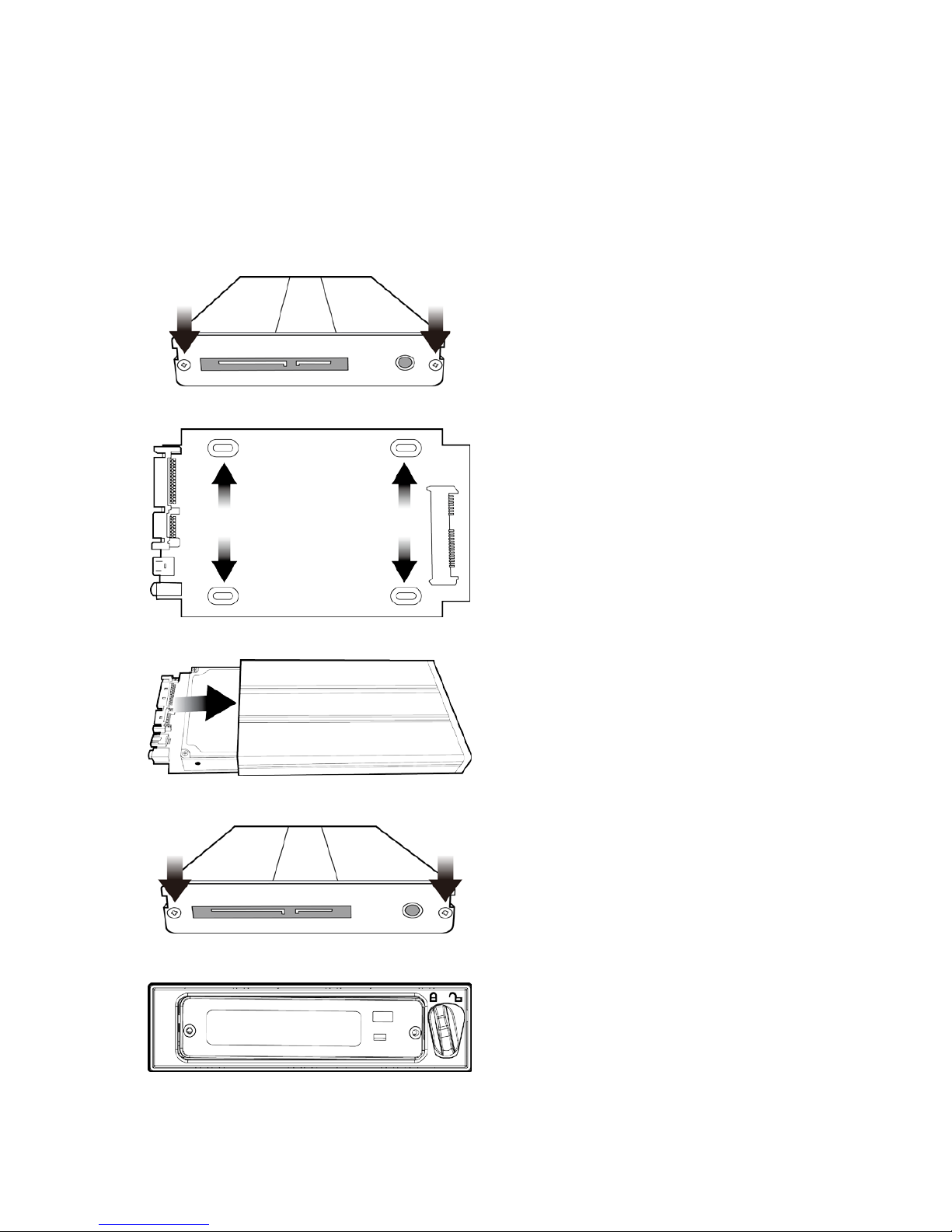
2.3 Removable Hard Disk Installation
How to Assemble 2.5" HDD in Removable Rack
Warning: You must use TVS-2000A proprietary HDD and not any Datavideo HDR series or DN
series.
Avoid HOT PLUGGING during operation (while writing to and reading from the disk) because
it may cause damage to the system and other files.
1. Remove the two screws on the rear cover
of the removable 2.5" HDD enclosure and
manually pull out the PCB
2. Tighten four screws to fasten 2.5" HDD on
the PCB as shown in the diagram below
3. Push the PCB with 2.5" HDD into the HDD
enclosure
4. Tighten the two screws of the rear cover of
the removable 2.5" HDD enclosure
5. Push the removable 2.5" HDD enclosure
into the front slot of the TVS-2000A system
11
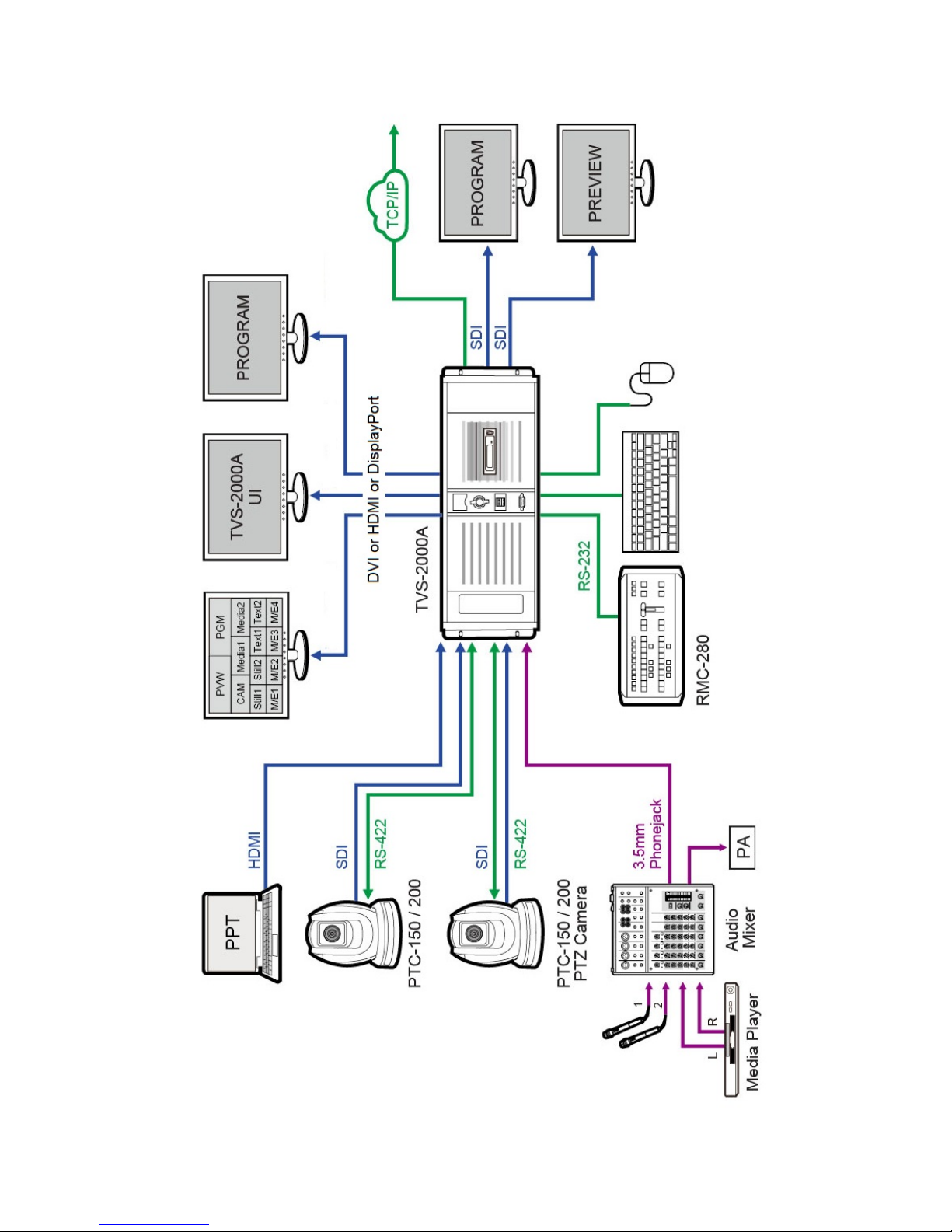
2.4 System Diagram
12
2.5 RMC-280 Remote Controller
The RMC-280 is a cost effective remote controller designed specifically for the TVS-2000A
Virtual Studio System. The RMC-280 interfaces with the TVS-2000A Virtual Studio System via
an RS-232 interface. The RMC-280 gives the user switcher-style control of the TVS-2000A
Virtual Studio System. There are several effects that the user can also control on the RMC-280,
such as downstream keyers (DSK) and transition effects. In addition, the T-Bar gives the user
the convenience to perform transitions between Preview (PVW) and Program (PGM).
The RMC-280 has also been equipped with 10 function keys, which provide the user with the
flexibility of manually assigning functions related to audio features, downstream keyer, delay,
media player functions and output effects to the 10 keys.
The features are summarized as follows:
• A switcher style keyboard for direct TVS-2000A operation
• Clear key definitions
• Ten user-defined function keys, F1 to F10 and each of these function keys can be:
Audio
DSK
General
Media
Output
V/C
Capture: Mute
Capture: Volume
Input: Mute
Input: Solo
Input: Volume
Output: Mute
Output: Volum e
Streaming: Mute
Streaming: Volume
Set Position
Set Preview
Set Rotation
Set Scale
Set Source
Transition Cut
Transition
Fade
Delay
Auto Play
Loop Play
Pause
Play
Select
Stop
Select Preview
Select Program
Transition CrossDissolve
Transition Fade
to Black
Transition Take
Studio: Load
Studio: Select Camera
Studio: Set Bus A Source
Studio: Set Bus B Source
Studio: Set Bus C Source
• Program/Preset Rows with buttons allowing the user to switch between CAM 1, CAM 2,
AUX, V/C 1, V/C 2, V/C 3, V/C 4, Media 1, Media 2, Still 1 and Still 2
• Ten custom-set phase buttons for virtual camera lens zoom in/out
• Linear and Curved buttons for respective camera movements.
• T-Bar can be operated in one way or two way mode
• TAKE button to switch between PVW and PGM views
• FTB button fades the PGM view to a black screen
• CROSS DISSOLVE button applies cross-dissolve transition effect to switching between PGM
and PVW views
• Two downstream keyers (DSK) with two corresponding knobs for assignment of DSK
sources
• CUT and AUTO TRANS buttons transition DSKs between PGM and PVW views
• STM button starts live video program streaming
• Capture function (CAP Button) records the live video program
• Still Grab function (GRAB Button) captures the instantaneous video image
• RS-232 interface for communication between RMC-280 and TVS-2000A
• 12V DC input making the unit ideal for studio applications
• Bright LED lighting
13
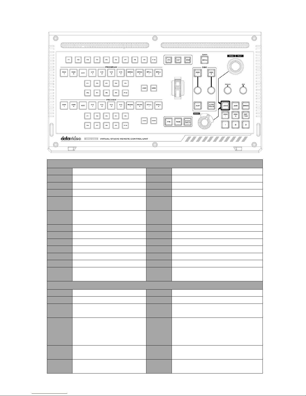
Control Panel Overview
TVS-2000A Virtual Studio Control Panel
F1-F10
Function Keys F1 – F10
Curved
Curved camera movement
CAM 1
Camera 1 view
P1-P10
Selection of position
CAM 2
Camera 2 view
FTB
Fade PGM to Black
AUX
AUX view
Take
Switch between PVW and PGM
V/C 1 V/C 1 view selection
Cross
Dissolve
Cross dissolve transition effect
V/C 2 V/C 2 view selection
Rolling
Wheel
Manual Transition
V/C 3
V/C 3 view selection
STM
Program Streaming
V/C 4
V/C 4 view selection
CAP
Video Recording
Media 1
Media 1 Video
Grab
Still Picture Grab
Media 2
Media 2 Video
DSK 1
DSK 1 and source assignment knob
Still 1
Still Picture 1
DSK 2
DSK 2 and source assignment knob
Still 2
Still Picture 2
CUT
Placement of DSK on Program
Linear Linear camera movement
AUTO
TRANS
Auto transition of the DSK to the
program view.
PTC-150 PTZ Camera Control Panel
Joystick
Camera panning and tilting
AWB
Automatic white balance
MENU
Opens the camera menu
Speed
Enable lens movement speed setting
FOCUS
Knob
Camera focus adjustment SET POS
Save current position into Lens
position 1 / 2 / 3
IRIS
Knob
Camera iris adjustment
While in the camera menu,
pressing the Knob selects or
confirms a selection.
CAM 1 Selection of Camera 1
Zoom
Knob
Camera zoom adjustment CAM 2 Selection of Camera 2
LOCK
Lock and Unlock PAN/TILT
joystick and ZOOM knob
1 / 2 / 3 Lens positions 1 / 2 / 3
14
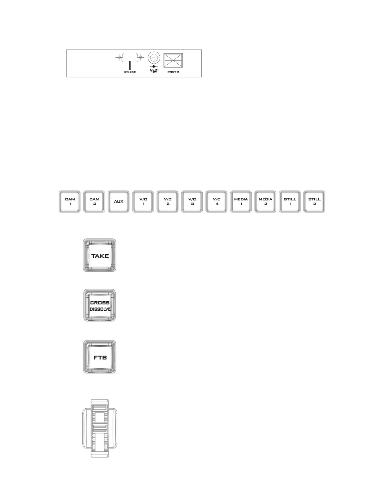
Main Unit - Rear Panel
RS-232: RS-232 Communication
Interface for connecting to the TVS2000A machine.
DC 12V: 12V DC Power Input
Power: ON/OFF Switch
Program and Preset rows
The Program row of buttons is for control of the program output; this is the live output. You
can switch or CUT from one video source to another directly on the Program row. You will see
the PGM output changes as you press different keys along this top row of buttons.
The Preset row of buttons is for control of the Preview window. The Preset row sets the next
transitioned program by pressing the corresponding key to select the source.
Preview and Program Switching
TAKE
This performs switching from the current program source to
the selected preset source.
Cross-Dissolve
This performs a cross-
dissolve switch from the current
program source to the selected preset source.
FTB
Fade To Black, this button fades the current video program
source to black. When pressed again it acts in reverse from
complete black to the currently selected program video
source.
Rolling Wheel (T-Bar)
This performs a manually controlled transition from the
current program source to the selected preset source. When
the rolling wheel has travelled as far as it can go, the transition
between sources is complete.
15
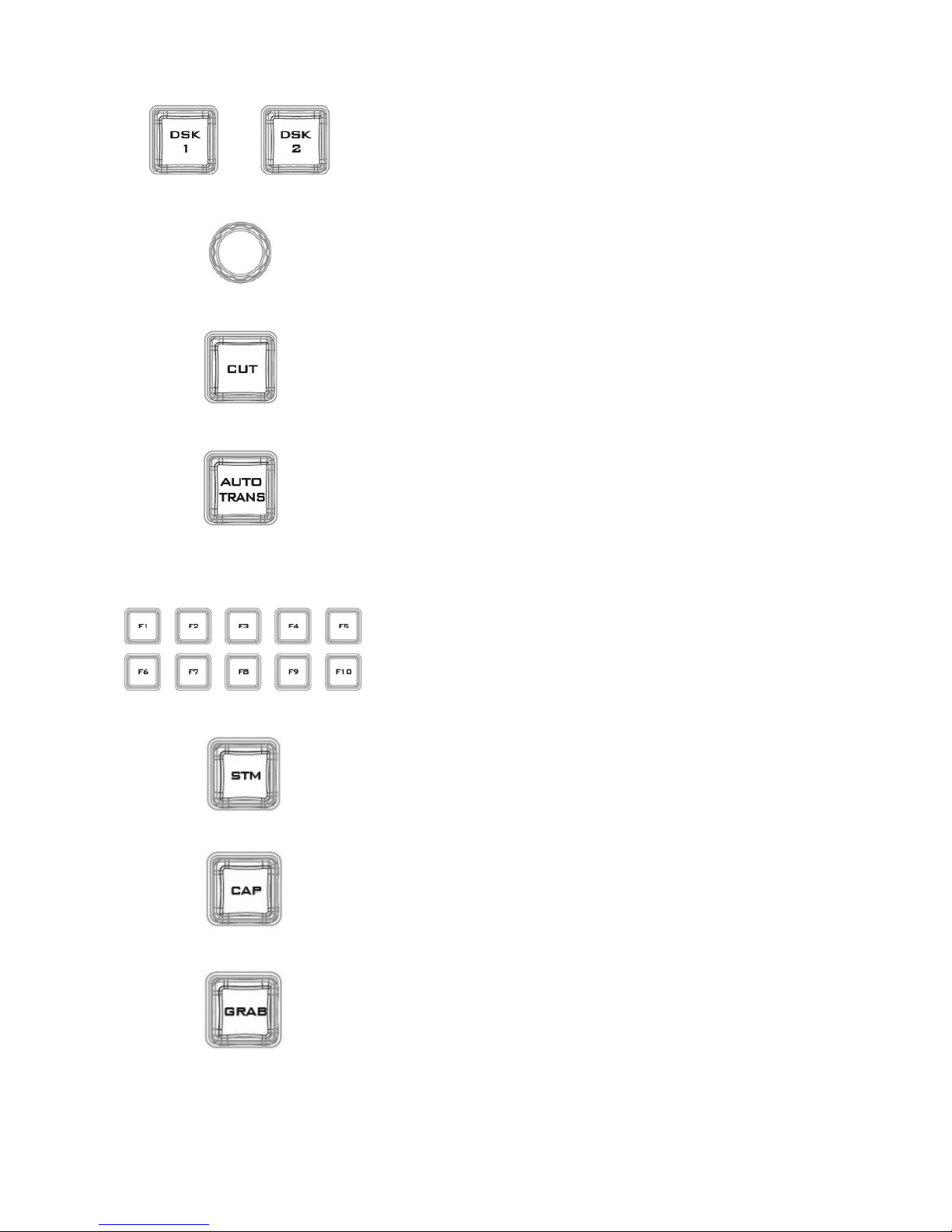
Downstream Keyers
D S K 1/2
Pressing DSK 1/2 places logo or animations on the program vie w.
Before placing the DSK on the program view, make sure it is
correct on the PVW screen first.
Control Knob
Assigns a source to DSK 1/2 from a selection of camera, video
files, and pictures
Cut
This cuts from the current key source to the selected key source.
Transition effect is not used.
AUTO TRANS
This performs an auto
transition switch from the current key
source to the selected key source.
Function Keys
F1 – F10
Ten user-defined function keys; please refer to the RMC-280
Function Keys section for more details
Stream
Start streaming the live video program to the Internet
Capture
Record the current live video program and save automatically to
the hard disk.
Still/Grab
Capture a frame of video and save automatically to the hard
disk.
16
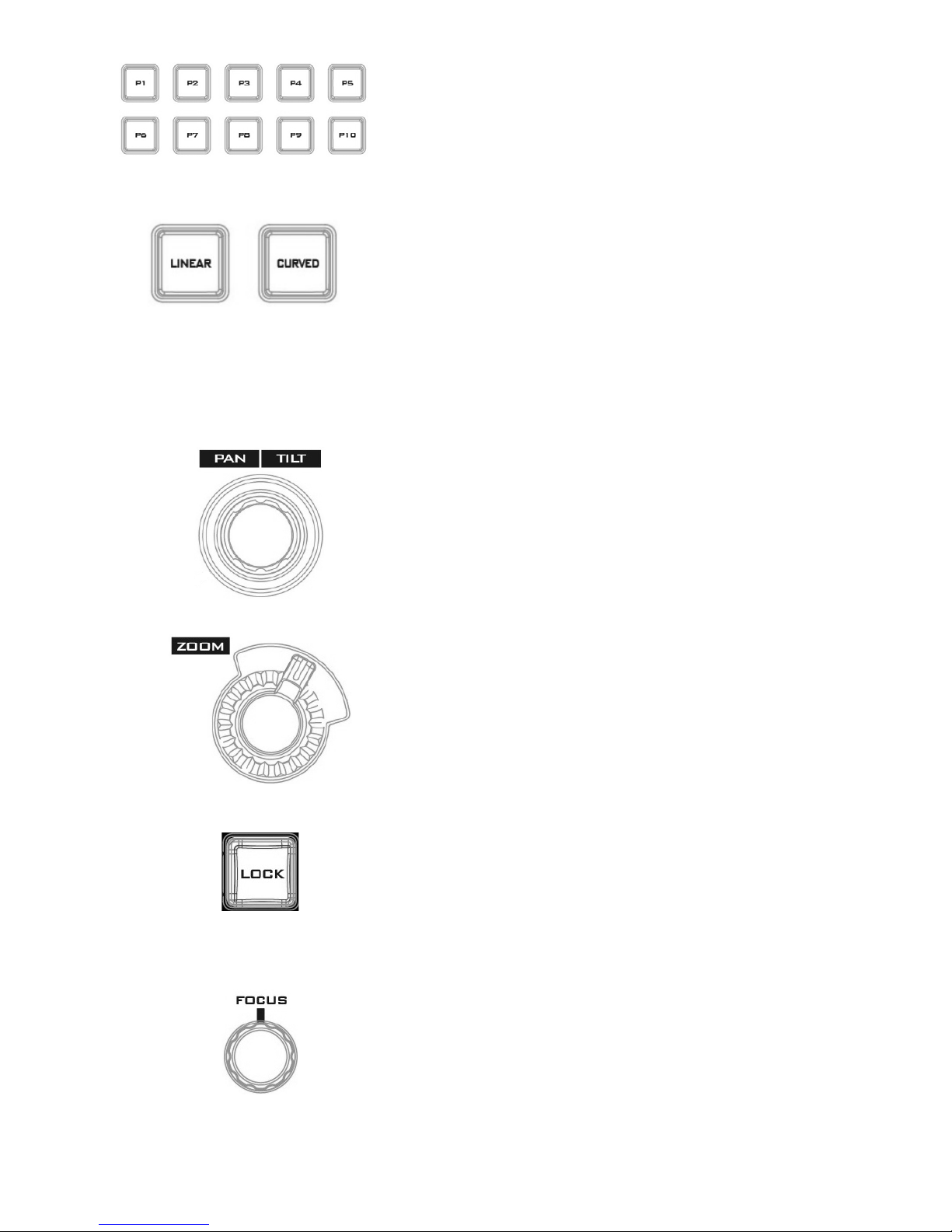
P1 – P10
P1 to P10 buttons allow the user to select a particular position
of a Virtual Camera (V/C).
Linear and Curved
In linear mode, the Virtual Camera moves between phases in a
linear fashion.
In curved mode, the Virtual Camera moves between phases in
an arc like path.
PTZ Camera Control
Joystick
Move the joystick sideways to PAN the camera lens. To TILT
the camera lens, move the joystick up and down.
ZOOM Wheel
Move the zoom wheel clockwise and counter-clockwise to
ZOOM IN/OUT the camera lens.
LOCK
Once the LOCK button is enabled, the joystick and ZOOM
wheel will be locked, i.e. the user will not be able to adjust
the PTZ settings using the joystick and the ZOOM wheel. To
unlock, simple press the LOCK button again.
FOCUS Knob
Rotate the FOCUS knob clockwise and counter-clockwise to
adjust the camera focus.
17
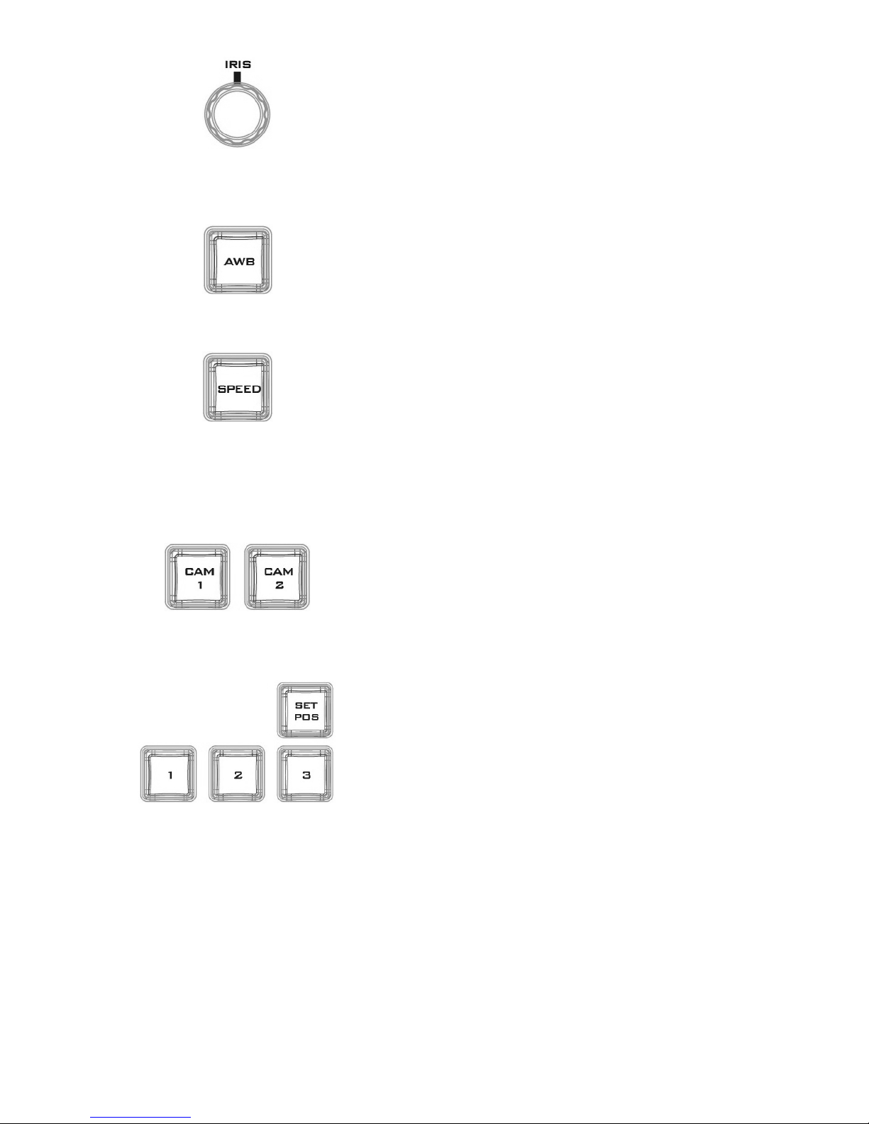
IRIS Knob
Rotate the IRIS knob clockwise and counter-clockwise to
adjust the camera iris.
Note: While in the camera menu, pressing the Knob
selects or confirms a selection.
AUTO White Balance
Pressing the AWB will automatically white balance the
camera.
Speed
Press the SPEED button to set camera lens movement
speed.
• Low Speed: Press once to turn the button white.
• Medium Speed: Press twice to turn the button pink.
• High Speed: Press three times to turn the button red.
C A M 1/2
Press CAM 1 button to select camera 1 and CAM 2 to select
camera 2. Only one camera can be selected at a time.
Camera Lens Positions
• Press the SET POS button to enable “SAVE POSITION”
function.
• Pressing button “1” saves current position into Lens
position 1.
• Pressing button “2” saves current position into Lens
position 2.
• Pressing button “3” saves current position into Lens
position 3.
Note: To recall a stored position, simply press button 1, 2
or 3.
18
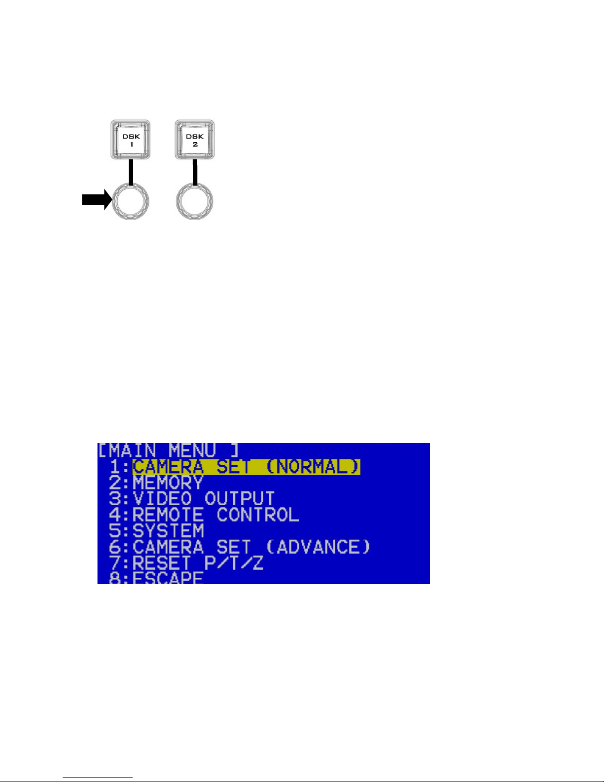
Keyboard Backlight
The RMC-280 allows the user to manually adjust the keyboard backlight. The steps are
outlined as follows:
1. Press the knob located below DSK1 key once and the DSK1 key will flash green
2. Rotate the knob right to enhance and left to dim
3. Press the knob again to turn off this feature
2.6 How to Calibrate the PTC-150 Camera Position for Your TVS-2000A
System
After finishing the basic system setup, please follow the steps below to optimize the visual
effect of the TVS-2000A’s tracking function.
Step 1: Make sure the tripod is placed on a flat surface and then mount the PTC-150 camera
on the tripod. Focus the camera on the center of the frame.
Step 2: Reset “Pan, Tilt, Zoom” of PTC-150 to factory default. Please select 7: Reset P/T/Z
Yes on the PTC-150’s main menu.
• Open the camera’s main menu.
• Move down the menu and select item 7 Reset P/T/Z.
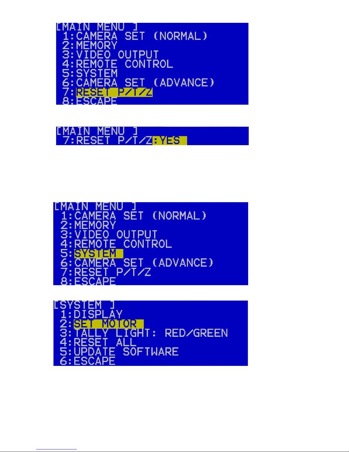
19
• Once in option 7, select YES to reset PAN, TILT and ZOOM values to factory defaults.
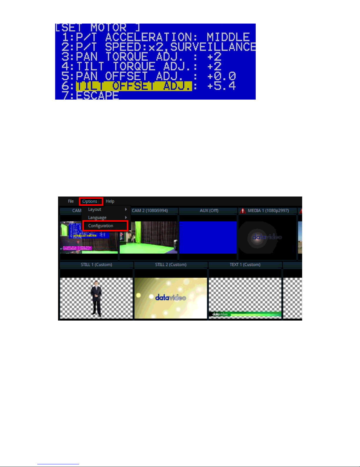
Step 3: Make sure the PTC-150 camera is positioned at a perfect horizontal line level. If the
camera is not positioned at the perfect horizontal line level, please open the main menu of the
PTC-150 camera and select 5: System 2: Set Motor 6: Tilt Offset ADJ. to fine tune the
camera’s vertical position to the perfect horizontal line level.
• Open the camera’s main menu and select the “System” option.
• Select “SET MOTOR.”
• Fine tune the camera position in the “TILT OFFSET ADJ.” option.
20
Step 4: Measure the height between the PTC-150 camera lens center to the ground in
centimeters.
Step 5: Measure the distance between the PTC-150 camera lens center to the object shot in
centimeters.
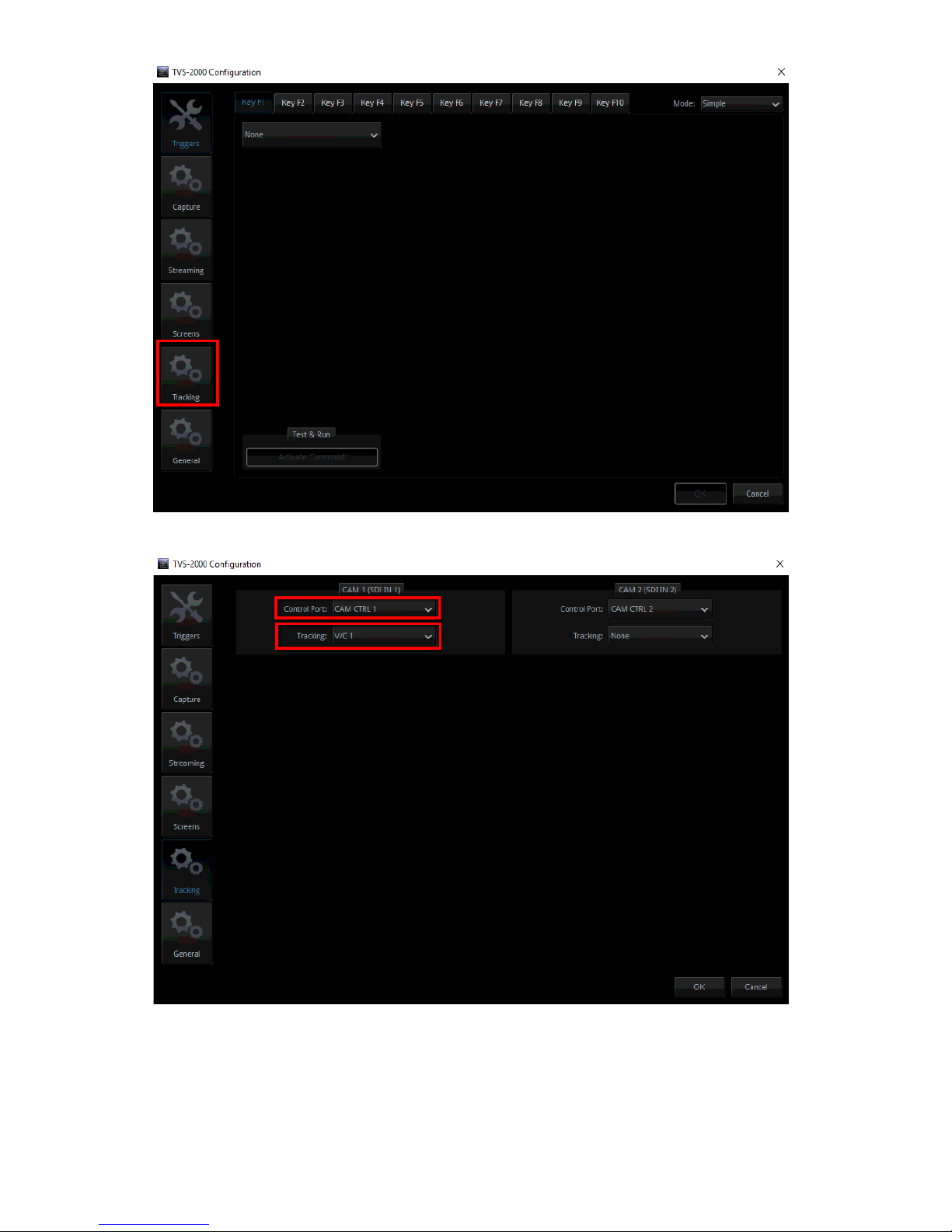
Step 6: Set the PTC-150 to Tracking Mode on the TVS-2000A user interface by selecting TVS-
2000A Configuration Window / Tracking tab / CAM 1 (SDI IN 1) / Camera Port: CAM CTRL 1 /
Tracking: V/C 1
• On the tool bar, select “Options” and then click “Configuration.”
• Click the “Tracking” tab.
21
• On the CAM 1 (SDI IN 1) pane, set the Control Port to CAM CTRL 1 and Tracking to V/C 1.
Step 7: At the bottom left of the Production User Interface, click V/C1 tab and enter “Camera
Setup.” At the top right corner of the Camera Setup screen, on the Position coordinates pane,
enter the previously measured height and distance into the Y and Z fields respectively and
then close the window.
• Click the Camera Setup button to open the Camera Setup window.
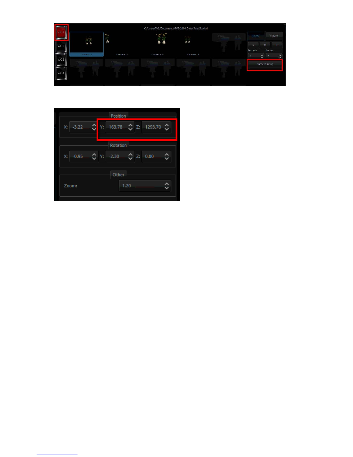
22
• Enter the previously measured height and distance into the Y and Z fields respectively
Step 8: At this point, you have done calibrating the PTC-150 camera position for the TVS-
2000A system and you may start using it as you wish.
 Loading...