

Datavideo TVS-1000, TVS-1200, TVS-1200A Instruction Manual

2
Table of Contents
WARRANTY ..................................................................................................................................................... 4
S
TANDARD WARRANTY ..................................................................................................................................... 4
T
WO YEAR WARRANTY ..................................................................................................................................... 4
DISPOSAL ........................................................................................................................................................ 4
CHAPTER 1 OVERVIEW ................................................................................................................................. 5
1.1
FEATURES ............................................................................................................................................ 5
CHAPTER 2 TVS-1000 TRACKLESS VIRTUAL STUDIO SETUP ........................................................................ 7
2.1
SYSTEM REQUIREMENT .......................................................................................................................... 7
2.2
CONNECTIONS ...................................................................................................................................... 7
2.2.1 Front Panel ................................................................................................................................ 7
2.2.2 Back Panel ................................................................................................................................. 7
2.2.3 Input/Output Card Options ....................................................................................................... 8
2.3
REMOVABLE HARD DISK INSTALLATION ..................................................................................................... 9
2.4
SYSTEM DIAGRAM ............................................................................................................................... 10
2.5
TVS-1000 AUX CARD ....................................................................................................................... 11
2.5.1 Introduction ............................................................................................................................. 11
2.5.2 Installation ............................................................................................................................. 11
2.5.3 Specification ............................................................................................................................ 12
2.6
RMC-220 REMOTE CONTROLLER .......................................................................................................... 12
2.6.1 Control Panel Overview ........................................................................................................... 13
2.6.2 Main Unit - Rear Panel ............................................................................................................ 14
2.6.3 Program and Preset rows ........................................................................................................ 14
2.6.4 Preview and Program Switching .............................................................................................. 14
2.6.5 Downstream Keyers ................................................................................................................. 15
2.6.6 Function Keys ........................................................................................................................... 15
2.6.7 Keyboard Backlight .................................................................................................................. 16
CHAPTER 3 STARTING TVS-1000 SOFTWARE ............................................................................................. 18
3.1
PRODUCTION LIVE ............................................................................................................................... 19
3.2
STILL TEXT EDIT .................................................................................................................................. 19
3.3
VIRTUALSET MAKER ......................................................................................................................... 20
3.4
RICH SITE SUMMARY (RSS) .................................................................................................................. 20
3.5
VIRTUALSET SHOP ............................................................................................................................ 21
3.6
CONFIGURATION ................................................................................................................................. 21
3.7
SHUTDOWN ....................................................................................................................................... 23
CHAPTER 4 VIRTUALSET MAKER................................................................................................................ 24
4.1
FEATURES .......................................................................................................................................... 24
4.2
GETTING START ED ............................................................................................................................... 25
4.3
VIRTUALSET MAKER TOUR .................................................................................................................... 26
4.4
USE CUSTOMIZED VIRTUALSET .............................................................................................................. 34
CHAPTER 5 PRODUCTION LIVE SCREEN ..................................................................................................... 35
5.1
TOOL BAR .......................................................................................................................................... 35
5.2
MULT I-VIEW AREA .............................................................................................................................. 36
5.3
PROGRAM AND PREVIEW ROWS & FUNCTION SETTINGS ............................................................................ 37
5.3.1 9-input Main Switcher ............................................................................................................. 38
5.3.2 Switching between Preview and Program Views .................................................................... 38
5.3.3 Downstream Keys .................................................................................................................... 38
5.4
VIRTUAL BACKGROUND EDITING ............................................................................................................ 40
5.4.1 Import ...................................................................................................................................... 41

3
5.4.2 Placement ................................................................................................................................ 41
5.4.3 Auto Play ................................................................................................................................. 42
5.5 F
ILE MANAGEMENT ............................................................................................................................. 43
5.6
ADDITIONAL MONITOR SUPPORT ........................................................................................................... 47
5.6.1 General Display Settings .......................................................................................................... 48
CHAPTER 6 CHROMA AND LUMA KEYS ..................................................................................................... 49
6.1
KEY SELECTION ................................................................................................................................... 49
6.2
CHROMA KEY ..................................................................................................................................... 49
6.3
MATTE CONTROL ................................................................................................................................ 50
6.4
TOLERANCE CORRECTION ..................................................................................................................... 52
6.5
SPILL CORRECTION .............................................................................................................................. 54
6.6
EDGE CORRECTION .............................................................................................................................. 56
6.7
GARBAGE MASK ................................................................................................................................. 56
6.8
POST CORRECTION .............................................................................................................................. 59
CHAPTER 7 FAST CHROMAKEYING ............................................................................................................ 59
7.1
SIMPLE CHROMA KEY .......................................................................................................................... 59
7.2
WIZARD ............................................................................................................................................ 60
CHAPTER 8 SOUND MIXER ......................................................................................................................... 61
CHAPTER 9 MOTION CAPTURE SPECIFICATION ........................................................................................ 62
CHAPTER 10 PROGRAM VIDEO STREAM ................................................................................................. 64
CHAPTER 11 EXTERNAL KEYBOARDS ....................................................................................................... 65
11.1
RMC-220 FUNCTION KEYS ............................................................................................................... 65
11.1.1 Advanced ..................................................................................................................................... 65
11.1.2 Simple ......................................................................................................................................... 66
11.2
STANDARD WINDOWS KEYBOARD SHORTCUTS ..................................................................................... 67
CHAPTER 12 SYSTEM RECOVERY .............................................................................................................. 68
CHAPTER 13 FREQUENTLY-ASKED QUESTIONS ........................................................................................ 71
CHAPTER 14 SPECIFICATIONS ................................................................................................................... 74
SERVICE & SUPPORT ..................................................................................................................................... 75
Disclaimer of Product and Services
The information offered in this instruction manual is intended as a guide only. At all times, Datavideo Technologies
will try to give correct, complete and suitable information. However, Datavideo Technologies cannot exclude that
some information in this manual, from time to time, may not be correct or may be incomplete. This manual may
contain typing errors, omissions or incorrect information. Datavideo Technologies always recommend that you
double check the information in this document for accuracy before making any purchase decision or using the
product. Datavideo Technologies is not responsible for any omissions or errors, or for any subsequent loss or
damage caused by using the information contained within this manual. Further advice on the content of this manual
or on the product can be obtained by contacting your local Datavideo Office or dealer.

4
Warranty
Standard Warranty
•
Datavideo equipment is guaranteed against any manufacturing defects for one year from
the date of purchase.
•
The original purchase invoice or other documentary evidence should be supplied at the
time of any request for repair under warranty.
•
Damage caused by accident, misuse, unauthorized repairs, sand, grit or water is not
covered by this warranty.
•
All mail or transportation costs including insurance are at the expense of the owner.
•
All other claims of any nature are not covered.
•
Cables & batteries are not covered under warranty.
•
Warranty only valid within the country or region of purchase.
•
Your statutory rights are not affected.
Two Year Warranty
•
All Datavideo products purchased after 01-Oct.-2008 qualify for a free one year extension
to the standard Warranty, providing the product is registered with Datavideo within 30 days
of purchase. For information on how to register please visit www.datavideo-tek.com or
contact your local Datavideo office or authorized Distributors
•
Certain parts with limited lifetime expectancy such as LCD Panels, DVD Drives, Hard Drives
are only covered for the first 10,000 hours, or 1 year (whichever comes first).
Any second year warranty claims must be made to your local Datavideo office or one of its
authorized Distributors before the extended warranty expires.
Disposal
For EU Customers only - WEEE Marking
This symbol on the product indicates that it will not be treated as
household waste. It must be handed over to the applicable take back
scheme for the recycling of electrical and electronic equipment. For more
detailed information about the recycling of this product, please contact
your local Datavideo office.

5
Chapter 1 Overview
TVS-1000 is a computer-based 2D trackless Virtual Studio System. It is a real-time production
system with very high quality live chromakeying.
TVS-1000 uses a single fixed camera and creates virtual cameras. This allows the director to
zoom, pan and tilt the camera virtually within the set. Its innovative Virtual Set Maker enables
users to create their own distinct, branded sets within minutes.
Integrated into the system are tools to record the program output, broadcast live and stream
over the Internet.
1.1 Features
Varieties of System Inputs with Front Object Integration
• Cameras (number dependent on system configuration);
• Media (videos) – two clips at the same time;
• Still images (bitmaps, text) – two at the same time;
• Text – two text compositions at the same time.
Additional Media Features
• A Media Bin is a simple-to-use interface that makes it possible to gather all the media
necessary for programme broadcast in one place;
• The media can be transferred from the bin to virtual players, used on air or as a source in
virtual studios;
• The system has six bin tabs for four kinds of media: videos, still images, and text;
• Logo insertion on virtual scene.
Virtual Background Features
• Load up to four virtual studio views simultaneously;
• Define movements of a virtual camera in different phases within every studio;
• Configurable Pan/Tilt/Zoom;
• Multi-Point Zoom;
• Virtual Studio backgrounds, which can be downloaded from Datavideo’s virtual
background database website;
• 30 free virtualsets available for downloads;
• CG-loaded backgrounds imported from external files, or edited by Still Text Editor.
Media Previews
• Camera preview (one or two at a time, depending on system configuration);
• Media preview (two at a time);
• Still image preview (two at a time);
• Text preview (two at a time);
• Up to four virtual studio previews;
• PREVIEW – presentation of the next element prepared for broadcast;
• PROGRAMME – presentation of the current programme broadcast (system output);
• Previews on multiple monitors (if monitors are connected to a workstation, it is possible
to obtain different preview configurations, even on three monitors);
• Real time streaming;
• Hard Drive (HD) Recording.

6
Supported Formats
• Format: 720p50 – image resolution: 1280 x 720
• Format: 720p60 – image resolution: 1280 x 720
• Format: 720p59.94 – image resolution: 1280 x 720
• Format: 1080i50 – image resolution: 1920 x 1080
• Format: 1080i60 – image resolution: 1920 x 1080
• Format: 1080i59.94 – image resolution: 1920 x 1080
• Format: 1080p25 – image resolution: 1920 x 1080
• Format: 1080p30 – image resolution: 1920 x 1080
• Format: 1080p29.97 – image resolution: 1920 x 1080
Video Processing Formats
• Video processing: 4:4:4 16-bit floating-point internal processing;
• Inputs and outputs: YUV 4:2:2;
• Capture in output format: 4:2:0;
• Streaming: 4:2:2.
Other Miscellaneous Features
• A Five-in-One System: Virtual Studio, Switcher, Character Generator, Recorder and Web
Streaming
• Multi-Language Support;
• RMC-220 Remote Control;
• Audio Embedding Capability;
• Real time streaming;
• Hard Drive (HD) Recording;
• Virtualset Maker;
• Optional TVS AUX Card for an additional input.
7
Chapter 2 TVS-1000 Trackless Virtual Studio Setup
2.1 System Requirement
Monitor x 1 (up to three monitors connected to choices of the HDMI x 1, DVI x 1,
DisplayPort x 3)
Keyboard
HDMI camera x 1 or SDI camera with a converter x 1
2.2 Connections
2.2.1 Front Panel
The front panel contains the RS-232 connection for operation with an external Datavideo RMC220 control panel. Access to the front panel is protected with a keyed door. This provides
protection against the system being accidentally switched off or reset or the data disk being
removed.
It is recommended that the workstation should be positioned so as to ensure air flows reaching
the front and the back panels. Fans providing appropriate system cooling are located behind the
panels. The workstation case is designed to be mounted on a server rack and occupies a 4U
space.
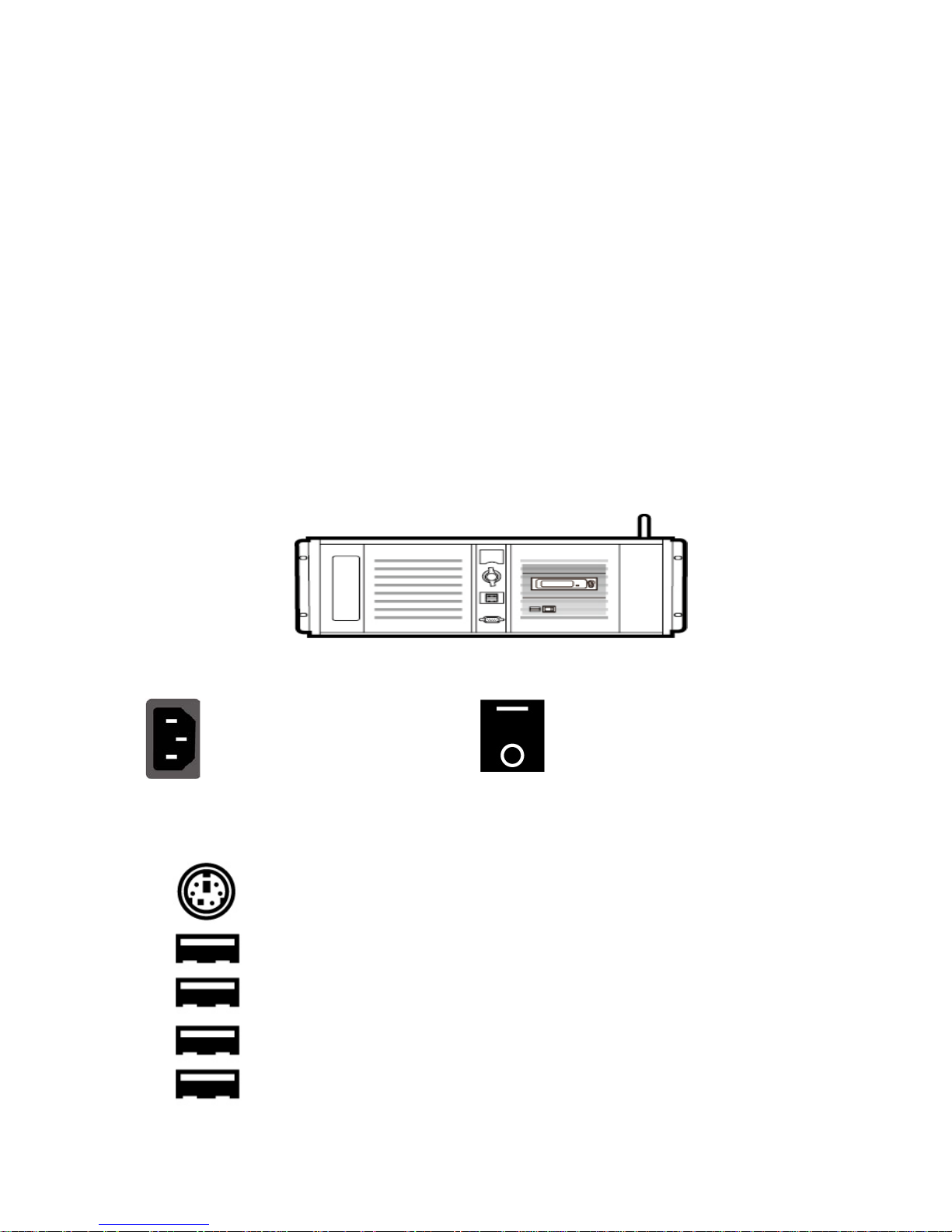
2.2.2 Back Panel
Power Supply Socket
Depending on the shipment
destination and the user
location, a power supply cord
with a suitable plug will be
supplied
Power On/Off Switch
Switches power On/Off
0 – OFF
1 – ON
PS/2 Keyboard / Mouse combo port
USB 2.0 ports
Connection of an external standard USB keyboard and mouse
USB 3.0 Ports (Blue)
Connection of USB Wireless Dongle / Adapter IF ANY
Please note that if you do not find the USB wireless dongle in the box,
the TVS-1200 System Unit that you receive may already have a built-in
wireless network card.
8
LAN (RJ-45) port
Connection of the workstation to a computer network
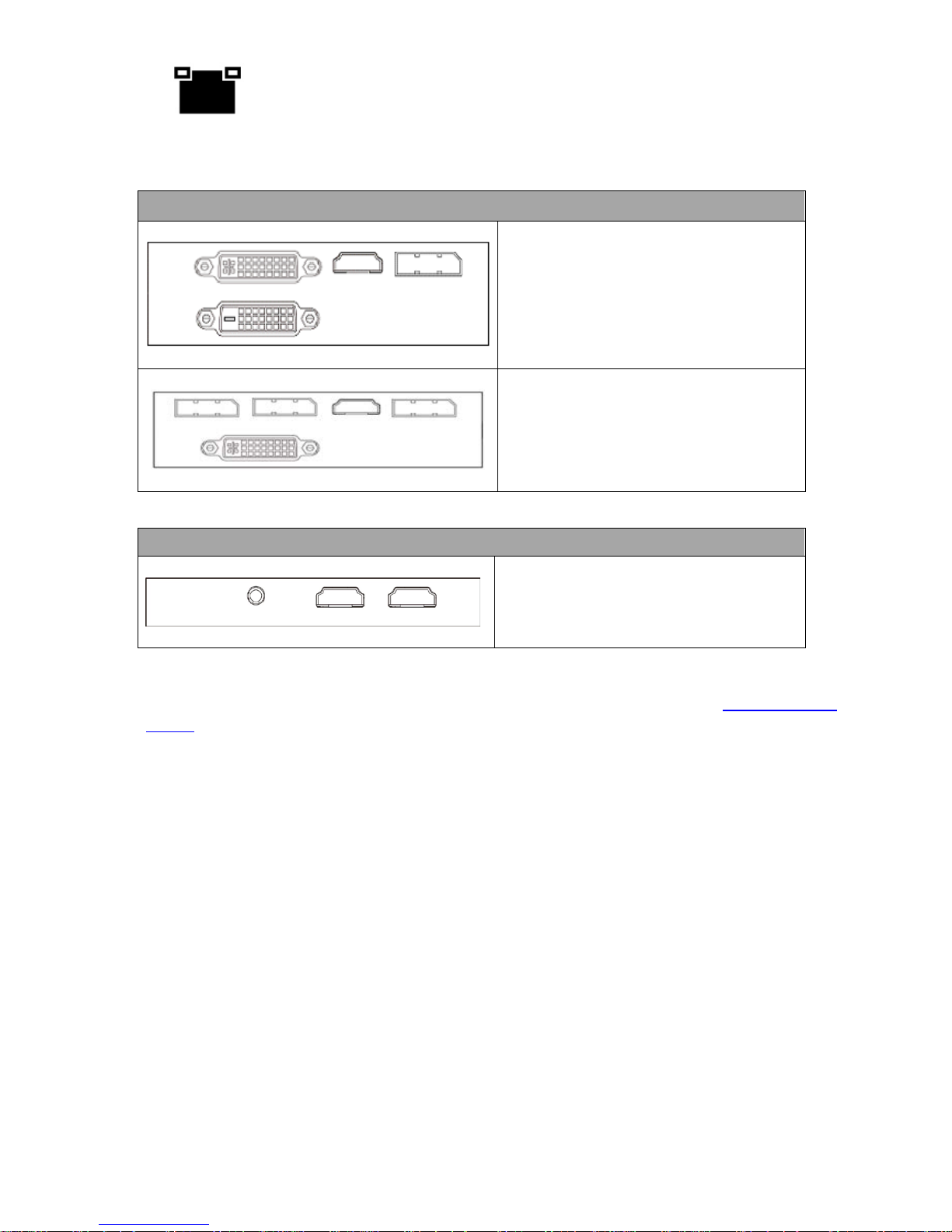
2.2.3 Input/Output Card Options
Display Card (One of the following)
Display card allows connection of two
DVI-D ports, one HDMI output port or
one DisplayPort.
Note: It is recommended
to connect
production window (M
onitor 1) to
HDMI port.
Display card allows connection of one
DVI-
I ports, one HDMI output port or
three DisplayPorts.
Virtu Card
Virtu card allows connection of a single
HDMI input/output pair and a mini
phone jack for audio input.
With both display and virtu SDI cards installed, it is thus possible to achieve different
combinations of views on the monitors. For more information, please refer to Configuration –
Layout section.
(MSI GTX 960)
9
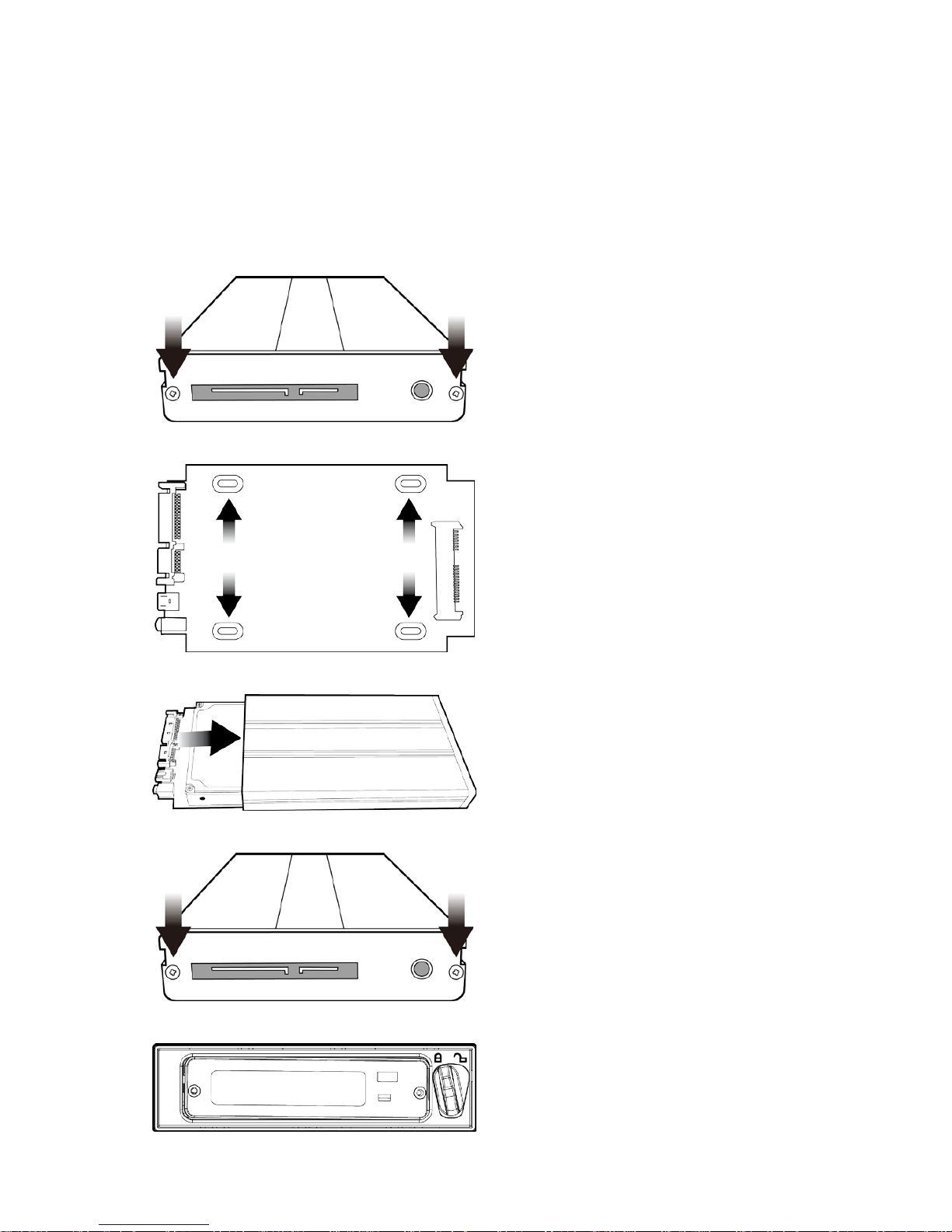
2.3 Removable Hard Disk Installation
How to Assemble 2.5" HDD in Removable Rack
Warning: You must use TVS-1000 proprietary HDD and not any Datavideo HDR series or DN
series.
Avoid HOT PLUGGING during operation (while writing to and reading from the disk) because it
may cause damage to the system and files.
1. Remove the two screws on the rear cover of
the removable 2.5" HDD enclosure and
manually pull out the PCB.
2. Tighten four screws to fasten 2.5" HDD on
the PCB as shown in the diagram below.
3. Push the PCB with 2.5" HDD into the HDD
enclosure.
4. Tighten the two screws of the rear cover of
the removable 2.5" HDD enclosure.
5. Push the removable 2.5" HDD enclosure into
the front slot of TVS-1000 system.
10
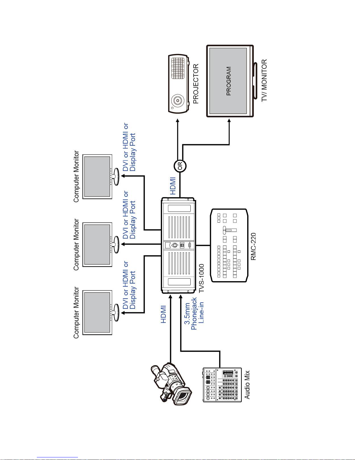
2.4 System Diagram
11
2.5 TVS-1000 AUX Card
2.5.1 Introduction
TVS Virtu AUX Card is designed primarily for powerpoint file input via HDMI port as well as for
other applications such as media player or camera input. TVS AUX card can also be used in TVS-
1200.
TVS-1000 Virtu HDMI Card and Virtu AUX Card Mapping Table
Card Type
H/W
Version
Workable w/
AUX Card
Remark
Virtu HDMI
1.0 X HDMI Ver 1.0 H/W limited.
1.2 X HDMI Ver 1.2 H/W limited.
1.3 ∆
Functional but with warning
messages
1.4 O
Table 1: TVS-1000 Virtu HDMI Card and Virtu AUX Card Mapping Table
Above table points out Virtu HDMI card H/W ver 1.0 & 1.2 cannot be workable with Virtu AUX
card. Only Virtu HDMI card H/W version above 1.3 can work with Virtu AUX card.
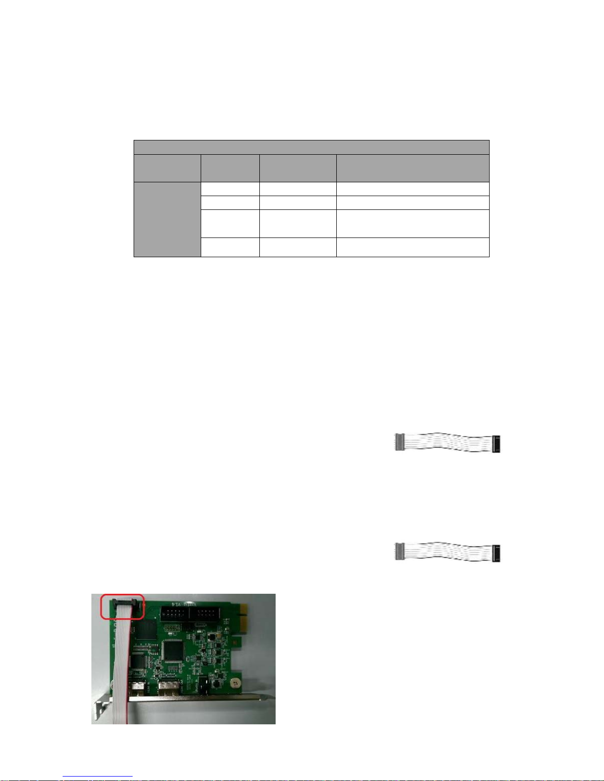
2.5.2 Installation
There are two models of motherboard used for TVS-1000 PC System: ASUS H87-PRO (white PCIe
slot) and ASUS H97-PRO (black PCIe slot)
ASUS H87-PRO Motherboard
1. Remove Wi-Fi card
2. Insert AUX card in the Wi-Fi card slot
3. For TVS-VIRTU HDMI Card Version 1.4, use the cable
shown to the right to connect between TVS Virtu AUX
card and TVS Virtu HDMI card
ASUS H97-PRO Motherboard
1. Remove Wi-Fi card and insert it in the slot located between HDMI card and video card
2. Insert AUX card in the Wi-Fi card slot (PCIe)
3. For TVS-VIRTU HDMI Card Version 1.4, use the cable
shown to the right to connect between TVS Virtu AUX
card and TVS Virtu HDMI card
The cable connection between TVS Virtu AUX card and
TVS Virtu HDMI card is depicted in the diagram below.
The location of the slot for the cable connection is
circled in red as shown in the diagram on the left. Both
cards should have the identical slot at the same
location.
12
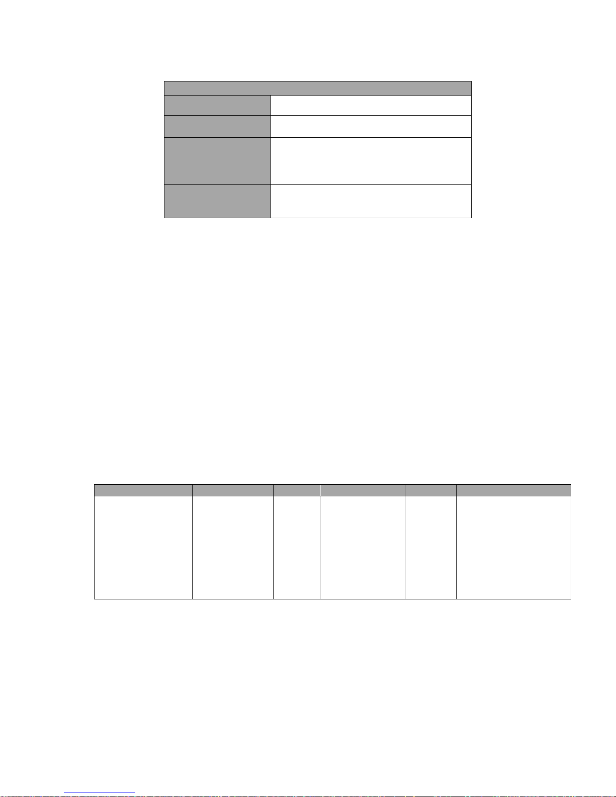
2.5.3 Specification
TVS Virtu Aux Card
Video Input
HDMI x 1
Video Output
HDMI x 1 (Preview without audio)
Video Input Format
1080 30P/29.97P/25P
1080 60i/59.94i/50i
720 60P/59.94P/50P
Audio Input
Mini Phone Jack x 1
HDMI audio embedded
2.6 RMC-220 Remote Controller
The RMC-220 is a cost effective remote controller designed specifically for the TVS-1000 Virtual
Studio System. The RMC-220 interfaces with the TVS-1000 Virtual Studio System via an RS-232
interface. The RMC-220 gives the user switcher-style control of the TVS-1000 Virtual Studio
System. There are several effects that the user can also control on the RMC-220, such as
downstream keyers (DSK), logo insertion, and transition effects. In addition, the T-Bar gives the
user the convenience to perform transitions between Preview (PVW) and Program (PGM).
The RMC-220 has also been equipped with 10 function keys, which provide the user with the
flexibility of manually assigning functions related to audio features, downstream keyer, delay, mix
effect, media player functions and output effects to the 10 keys.
The features are summarized as follows,
• A switcher style keyboard for direct TVS-1000 operation
• Clear key definitions
• Ten user-defined function keys, F1 to F10 and each of these function keys can be:
Audio
DSK
General
Mix Effect
Media
Output
Capture Mute
Capture Volume
Input Mute
Input Solo
Input Volume
Output Mute
Output Volume
Streaming Mute
Streaming Volume
Set Position
Set Preview
Set Rotation
Set Scale
Set Source
Transition Cut
Transition Fade
Delay
Import Studio
Set AutoPlay
Set Bus A Source
Set Bus B Source
Set Phase
Set Speed
Auto Play
Loop Play
Pause
Play
Select
Stop
Select Preview
Select Program
Transition Cross-Dissolve
Transition Fade to Black
• Program/Preset Rows with buttons allowing the user to switch between CAM1, CAM2,
ME1, ME2, ME3, ME4, Media1, Media2, Still1 and Still2
• Three custom-set phase buttons for virtual camera lens zoom in/out
• Auto play button for automatic movement of the virtual camera
• T-Bar can be operated in one way or two way mode
• Take button to switch between PVW and PGM views
• FTB button fades the PGM view to a black screen
• Cross Dissolve button applies cross-dissolve transition effect to switching between PGM
and PVW views
13
• Two downstream keyers (DSK) with two corresponding knobs for assignment of DSK
sources
• Cut and Fade buttons transition DSKs between PGM and PVW views
• Stream button triggers live video program streaming
• Capture function records the live video program
• Still Grab function captures the instantaneous video image
• RS-232 interface for communication between RMC-220 and TVS-1000
• 12V DC input making the unit ideal for studio applications
• Bright LED lighting
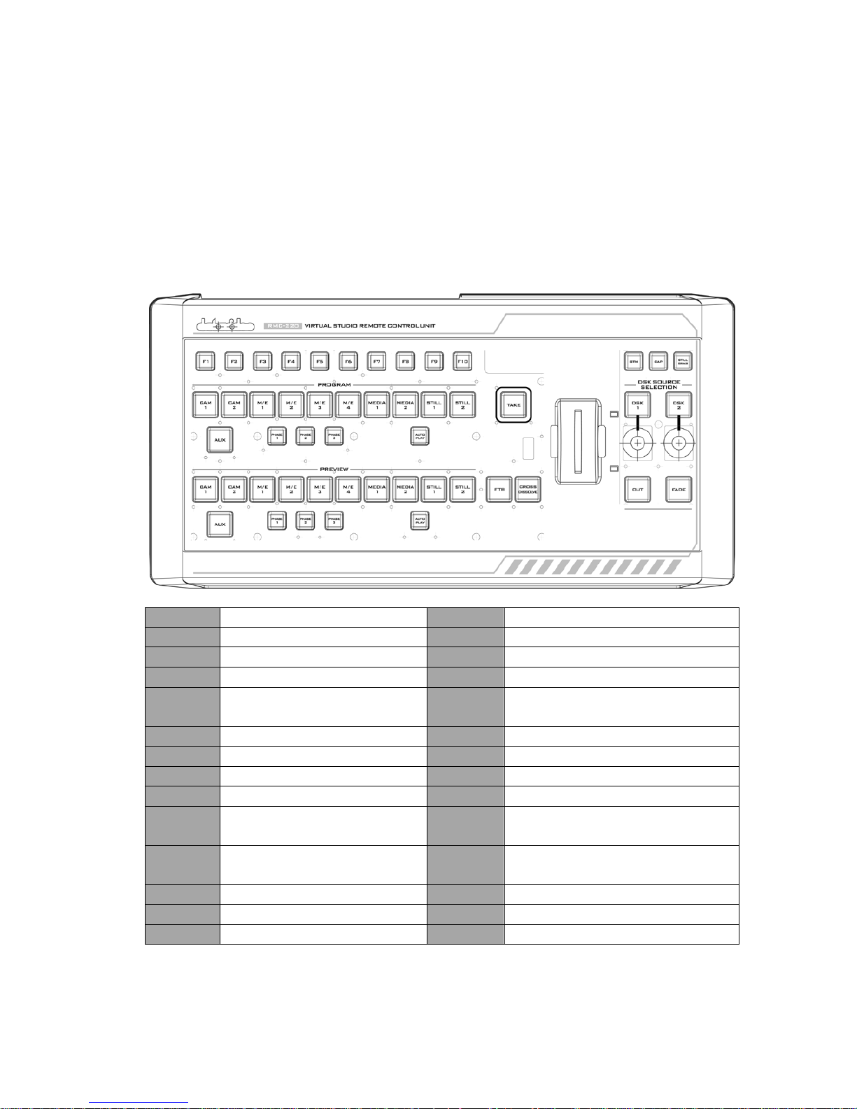
2.6.1 Control Panel Overview
F1-F10
Function Keys F1 – F10
Phase 3
Phase 3 selection
CAM 1
Camera 1 view selection
Auto Play
Auto Play function
*CAM 2
Camera 2 view selection
Take
Switch between PVW and PGM
M/E 1
M/E 1 view selection
FTB
Fade PGM to Black
M/E 2 M/E 2 view selection
Cross
Dissolve
Cross dissolve transition effect
M/E 3
M/E 3 view selection
T-Bar
Manual Transition
M/E 4
M/E 4 view selection
STM
Program Streaming
Media 1
Media 1 Video selection
CAP
Video Recording
Media 2
Media 2 Video selection
Still Grab
Still Picture Grab
Still 1 Still Picture 1 selection DSK 1
DSK 1 and source assignment
knob
Still 2 Still Picture 2 selection DSK 2
DSK 2 and source assignment
knob
AUX
AUX Card Input selection
Cut
Placement of DSK on Program
Phase 1
Phase 1 selection
Fade
Gradual placement of DSK
Phase 2
Phase 2 selection
*Not available on TVS-1000
14
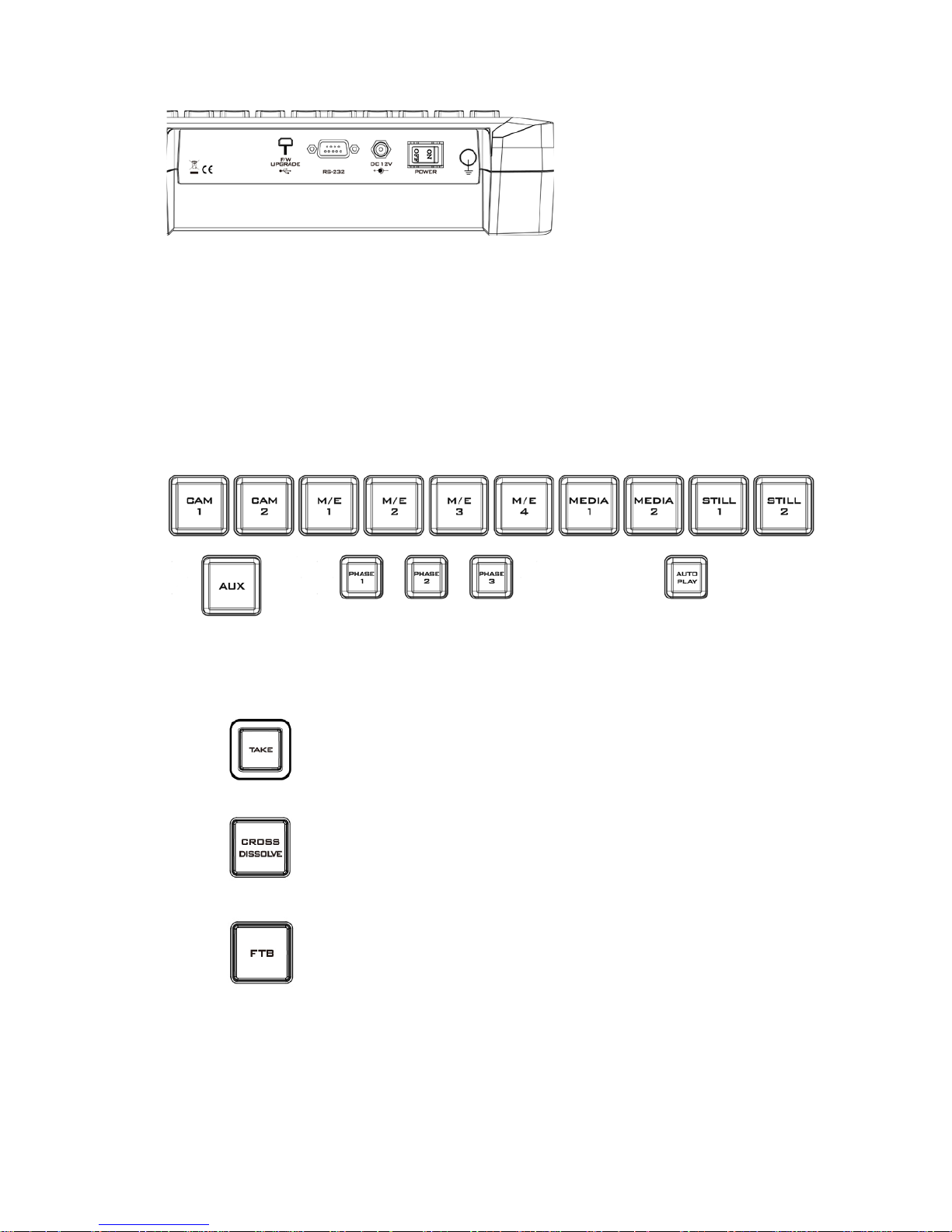
2.6.2 Main Unit - Rear Panel
RS-232: RS-232 Communication
Interface
DC 12V: 12V DC Power Input
ON/OFF: Power Button
2.6.3 Program and Preset rows
The Program row of buttons is for control of the program output; this is the live output. You can
switch or CUT from one video source to another directly on the Program row. You will see the
PGM output changes as you press different keys along this top row of buttons.
The Preset row of buttons is for control of the Preview window. The Preset row sets the next
transitioned program by pressing the corresponding key to select the source.
2.6.4 Preview and Program Switching
TAKE
This performs switching from the current program
source to the selected preset source.
Cross-Dissolve
This performs a cross-
dissolve switch from the current
program source to the selected preset source.
FTB
Fade To Black, this button fades the current video
program source to black. When pressed again it acts in
reverse from complete black to the currently selected
program video source.
15
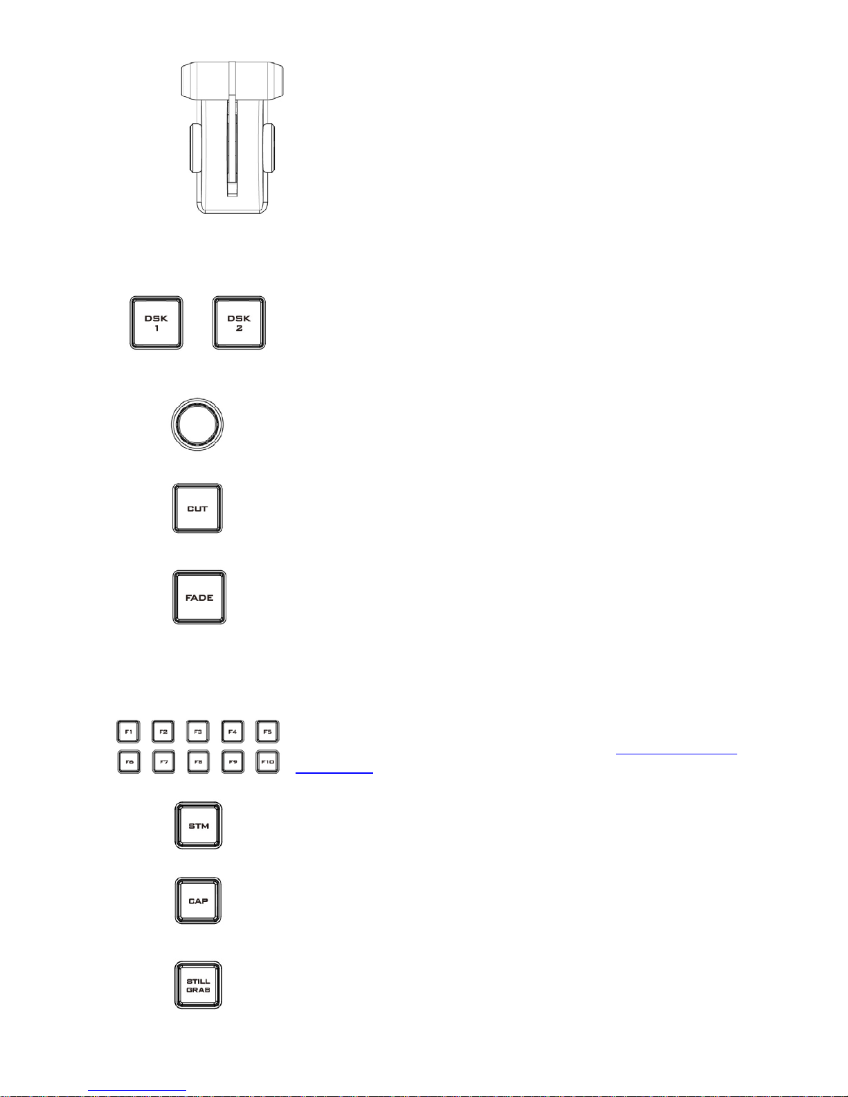
T-Bar
This performs a manually controlled transition from the
current program source to the selected preset source.
When the T-
Bar has travelled as far as it can go, the
transition between sources is complete.
2.6.5 Downstream Keyers
D S K 1/2
Pressing DSK 1/2 places logo or animations on the program view. Before
placing the DSK on the program view, make sure it is correct on the PVW
screen first.
Control Knob
Assigns a source to DSK 1/2 from a selection of camera, mix effects, video
files, and pictures
Cut
This cuts from the current key source to the selected key source.
Transition effect is not used.
Fade
This performs a fade transition switch from the current key source to the
selected key source.
2.6.6 Function Keys
F1 – F10
Ten user-defined function keys; please refer to the RMC-220 Function
Keys section for more details
Stream
Start streaming the live video program to the Internet
Capture
Record the current live video program and save automatically to the hard
disk.
Still/Grab
Capture a frame of video and save automatically to the hard disk.
16
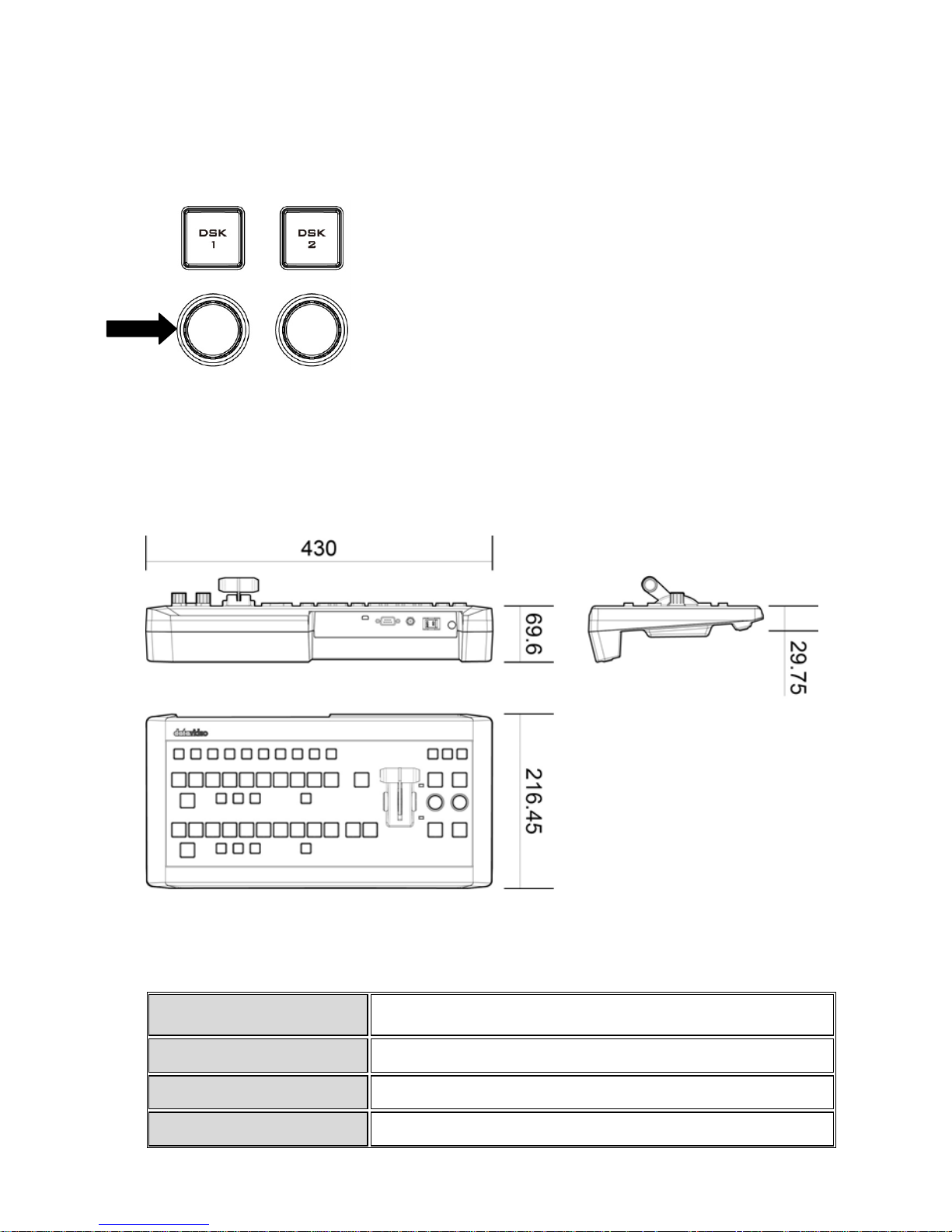
2.6.7 Keyboard Backlight
The RMC-220 allows the user to manually adjust the keyboard backlight. The steps are outlined
as follows:
1. Press the knob located below DSK1 key once and the DSK1 key will flash green
2. Rotate the knob right to enhance and left to dim
3. Press the knob again to turn off this feature
2.6.8 Dimensions
All measurements in millimetres (mm)
2.6.9 Specifications
Communication Interface RS-232
Baud Rate
38400 ODD
Power
DC12V ± 25%
Power Consumption
5W

17
Working Temperature
0°C +40°C
Storage Temperature
-20°C +60°C
Relative Humidity
≤ 90% (non-condensation)
Dimensions
Refer to Page 10
Net Weight
1.28Kg
Accessories
RS-232 Transmission Cable
DC In Power Adaptor
18
Chapter 3 Starting TVS-1000 Software
1. Connect power cord, keyboard, mouse, and RMC-220 to TVS-1000.
2. Connect one or multiple monitors to TVS-1000 via HDMI, DVI and Display Port.
3. Press the power button to boot the TVS-1000 hardware system. Power button is located on
the right of the red reset button; please refer to the Connections Section for the appearance
of the power button.
4. Important: Please ignore everything during the system boot-up process, which can take up to
approximately one minute, and you will be automatically directed to the TVS-1000 start-up
page. For more information, please refer to the System Recovery section.
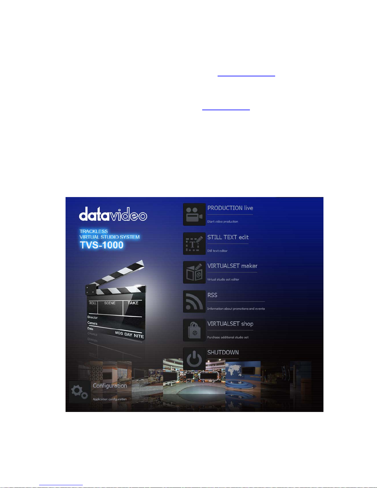
5. On the start-up page, seven options are available for the user to choose,
a. Production live
b. STILL TEXT edit
c. VIRTUALSET maker
d. RSS
e. VIRTUALSET shop
f. SHUTDOWN
g. Configuration
with details of which outlined in the subsections that follow.
Start-up Screen

19
3.1 Production Live
Start a new production by first selecting an appropriate video format. Supported Video formats
are 1080i60/59.94/50, 720p60/59.94/50, and 1080p30/29.97/25. Click on “Start Production”
button to start a new production. The user is also able to load previously saved production.
Choose a saved session from the pull-down menu as shown below and click on the “Load
Session” button to load previously saved production. You can also browse the hard drive to load
the previously saved session by clicking on the button .
3.2 Still Text Edit
The user can also open still text editior from start-up screen. Select a proper resolution first from
the pull-down menu and click on the “Start Editor” button to open the still text editor. The “Start
editor with recent Still” section allows the user to edit previously saved file by either selecting
from a pull-down menu or browsing the hard drive.
20
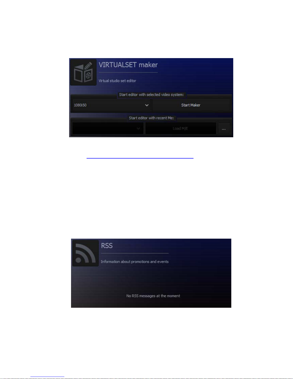
3.3 VIRTUALSET Maker
VIRTUALSET maker is designed for the user to edit and make their own virtualset. Again, select a
proper resolution first from the pull-down menu and click on the “Start Editor” button to open
the virtualset edito r.
The Virtualset Maker can also be used as a standalone application on the PC and may be
downloaded from http://www.datavideo.com/TVS-Virtualsetmaker. The PC needs to meet the
minimum system requirements as described below:
•
CPU: i3 Processor or faster
•
Memory: 4GB RAM
•
Graphic Card: GPU with DirectX 11
•
Operating System: Windows 7 (64 bits) or above
•
Monitor resolution of 1680 x 1050 or higher
3.4 Rich Site Summary (RSS)
The RSS feature allows Datavideo to publish updated information to the user. The information
can be in the form of blog entries, news headlines, audio or video.
21
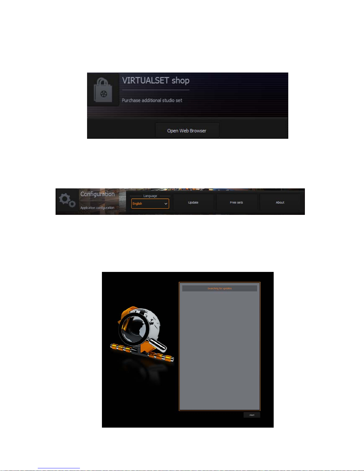
3.5 VIRTUALSET Shop
If the user would like to expedite production and avoid the hassles of creating their own virtual
background, simply visit the VIRTUALSET shop to download currently available studio sets by
clicking on the “Open Web Browser” button.
3.6 Configuration
Configuration offers the user four basic functions: language selection, firmware update, free
virtualset download and system summary.
Language: A pull-down menu allowing the user to choose a desired language from English,
Simplified Chinese and Traditional Chinese
Update: When clicked, the following window appears while the system searches for firmware
update
22
Free sets: Click on this button and follow the instruction below to download free sets from the
Internet
How to download free sets if you already have an account on
http://www.datavideovirtualset.com/?
• On the TVS-1000 main screen, select configuration then click the “Free Sets”
• Enter your email address then click “download free sets”
• Please be patient while downloading
• After free sets are downloaded successfully, click “OK” to go back to main screen
How to download free sets if you DO NOT have an account on
http://www.datavideovirtualset.com/?
• On the TVS-1000 main screen, select configuration then click the “Free Sets”
• Enter your registration info then click “Register”
• Please be patient while downloading
• After free sets are downloaded successfully, click “OK” to go back to main screen
Or you can also scan the QR Code on the right to open a video
tutorial showi
ng you how you can download free sets from the
Internet.
To access the video tutorial that will get you started on the TVS1000 Virtual Studio System, simply scan the QR code on the right
with your phone.
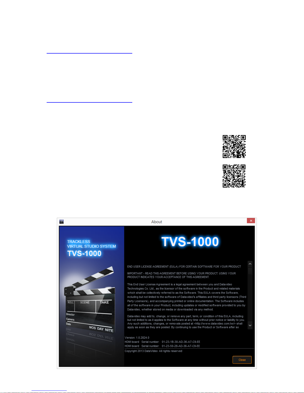
About: A pop-up window will appear, displaying information such as EULA, Version number, and
Serial Number
23
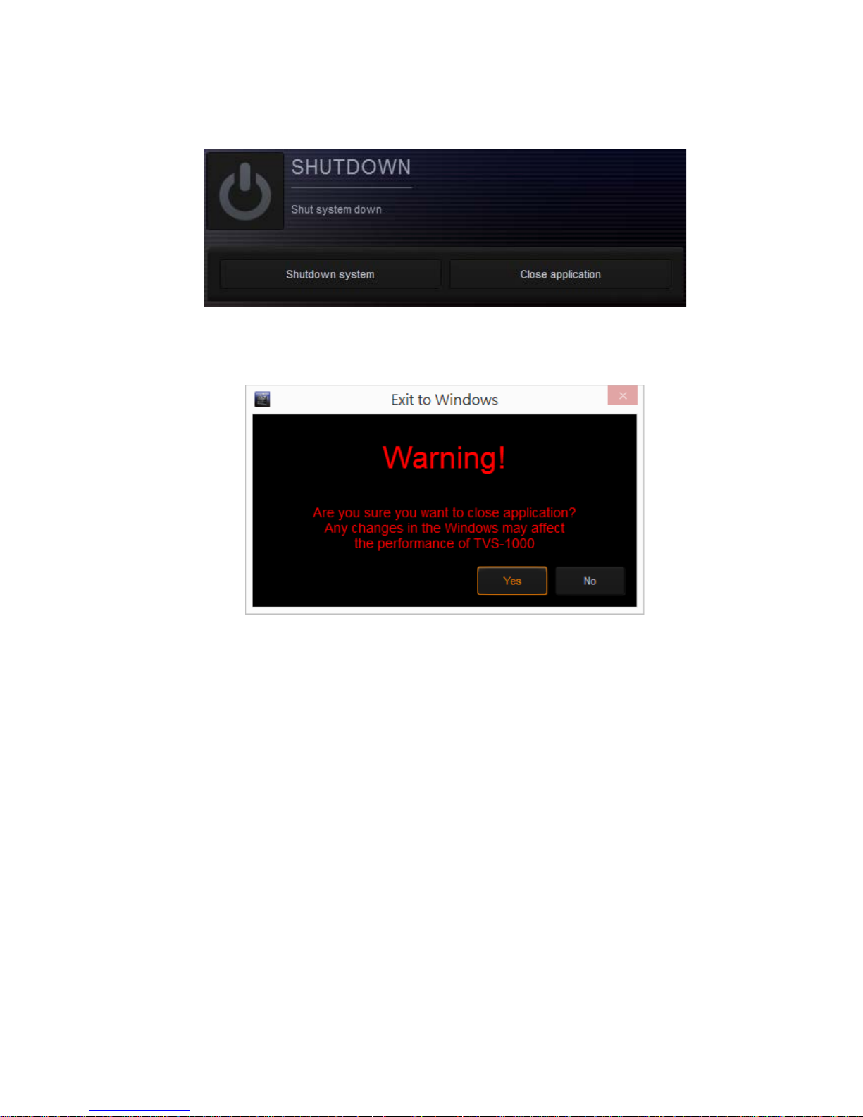
3.7 Shutdown
To exit the startup panel, the user can simply click on the “Close application” button or the
“Shutdown system” button to shut down the system.
Note: A popup warning dialogue box will appear as shown below after you click on the “Close
application” button.
 Loading...