

Page 1
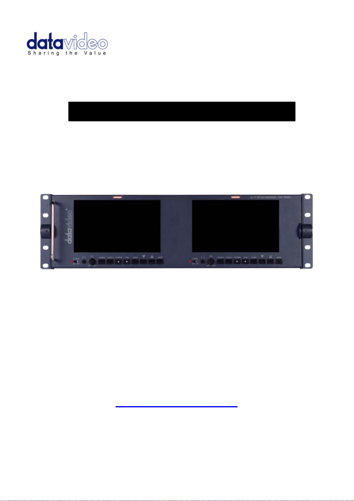
2 x 7" TFT LCD MONITOR
TLM-702HD
Instruction Manual
Rev 150310
www.datavideo-tek.com
Page 2

Table of Contents
Warnings and Precautions ......................................................................................................... 3
Warranty ..................................................................................................................................... 4
Standard Warranty .................................................................................................................. 4
Two Year Warranty ................................................................................................................. 4
Disposal ..................................................................................................................................... 4
Packing List ................................................................................................................................ 4
Introduction ................................................................................................................................ 5
Features ..................................................................................................................................... 5
Supported Formats ..................................................................................................................... 5
Connections & Control ............................................................................................................... 6
Front Panel .............................................................................................................................. 6
Rear Panel .............................................................................................................................. 7
Menu Options ............................................................................................................................. 8
1. Picture ................................................................................................................................. 8
2. Audio ................................................................................................................................... 8
3. Func. ................................................................................................................................... 8
4. Setup ................................................................................................................................... 8
5. Advance .............................................................................................................................. 9
Calibrating Datavideo Monitors ................................................................................................ 10
Specifications ........................................................................................................................... 10
Service & Support .................................................................................................................... 11
2
Page 3

Warnings and Precautions
1. Read all of these warnings and save them for later reference.
2. Follow all warnings and instructions marked on this unit.
3. Unplug this unit from the wall outlet before cleaning. Do not use liquid or aerosol
cleaners. Use a damp cloth for cleaning.
4. Do not use this unit in or near water.
5. Do not place this unit on an unstable cart, stand, or table. The unit may fall, causing
serious damage.
6. Slots and openings on the cabinet top, back, and bottom are provided for ventilation. To
ensure safe and reliable operation of this unit, and to protect it from overheating, do not
block or cover these openings. Do not place this unit on a bed, sofa, rug, or similar
surface, as the ventilation openings on the bottom of the cabinet will be blocked. This
unit should never be placed near or over a heat register or radiator. This unit should not
be placed in a built-in installation unless proper ventilation is provided.
7. This product should only be operated from the type of power source indicated on the
marking label of the AC adapter. If you are not sure of the type of power available,
consult your Datavideo dealer or your local power company.
8. Do not allow anything to rest on the power cord. Do not locate this unit where the power
cord will be walked on, rolled over, or otherwise stressed.
9. If an extension cord must be used with this unit, make sure that the total of the ampere
ratings on the products plugged into the extension cord do not exceed the extension
cord’s rating.
10. Make sure that the total amperes of all the units that are plugged into a single wall outlet
do not exceed 15 amperes.
11. Never push objects of any kind into this unit through the cabinet ventilation slots, as
they may touch dangerous voltage points or short out parts that could result in risk of
fire or electric shock. Never spill liquid of any kind onto or into this unit.
12. Except as specifically explained elsewhere in this manual, do not attempt to service this
product yourself. Opening or removing covers that are marked “Do Not Remove” may
expose you to dangerous voltage points or other risks, and will void your warranty.
Refer all service issues to qualified service personnel.
13. Unplug this product from the wall outlet and refer to qualified service personnel under
the following conditions:
a. When the power cord is damaged or frayed;
b. When liquid has spilled into the unit;
c. When the product has been exposed to rain or water;
d. When the product does not operate normally under normal operating conditions.
Adjust only those controls that are covered by the operating instructions in this
manual; improper adjustment of other controls may result in damage to the unit
and may often require extensive work by a qualified technician to restore the unit
to normal operation;
e. When the product has been dropped or the cabinet has been damaged;
f. When the product exhibits a distinct change in performance, indicating a need for
service.
3
Page 4
Warranty
Standard Warranty
Datavideo equipment is guaranteed against any manufacturing defects for one year
from the date of purchase.
The original purchase invoice or other documentary evidence should be supplied at the
time of any request for repair under warranty.
Damage caused by accident, misuse, unauthorized repairs, sand, grit or water is not
covered by this warranty.
All mail or transportation costs including insurance are at the expense of the owner.
All other claims of any nature are not covered.
Cables & batteries are not covered under warranty.
Warranty only valid within the country or region of purchase.
Your statutory rights are not affected.
Two Year Warranty
All Datavideo products purchased after 01-Oct.-2008 qualify for a free one year extension
to the standard Warranty, providing the product is registered with Datavideo within 30
days of purchase. For information on how to register please visit www.datavideo-tek.com
or contact your local Datavideo office or authorized Distributors
Certain parts with limited lifetime expectancy such as LCD Panels, DVD Drives, Hard
Drives are only covered for the first 10,000 hours, or 1 year (whichever comes first).
Any second year warranty claims must be made to your local Datavideo office or one of
its authorized Distributors before the extended warranty expires.
Disposal
Packing List
For EU Customers only - WEEE Marking
This symbol on the product indicates that it should not be treated as
household waste. It must be handed over to the applicable take-back
scheme for the recycling of waste electrical and electronic equipment. For
more detailed information about the recycling of this product, please contact
your local Datavideo office.
Items Description Q’ty
1 TLM-702HD 1
2 AC Power Cord 1
3 1.5 ψHex Wrench 1
4 2.5 ψHex Wrench 1
5 Switching Adaptor DC 12V/30W 1
6 User’s Manual 1
4
Page 5

Introduction
The Datavideo TLM-702HD is a 19” rack mountable dual 7” TFT Monitor. The all metal
construction makes the TLM-702HD robust and durable, and the 12V DC power requirements
make it easy to power in the field. The high resolution TFT screens have a wide viewing angle
and feature NTSC / PAL auto detection.
Features
2 x 7" 16:9 Wide Screen Panels
Resolution: 800 x 480 dots
View Angle (V)+60/-40°, (H)+60/-60°
HD/SD-SDI, YUV, HD-YUV, HDMI & CV Input
Internal colour bar
Blue only function
Embedded Audio indicator for SDI, HDMI signals
Safe Area indicator
VITC time code display
Dual colour tally light indicator
Brightness, Contrast, Colour, Tint Adjustable
Colour Temp* Adjustable
Audio Level indicators
NTSC / PAL Auto Switching
4:3 / 15:9 / 16:9 switchable
* Colour Temp can be set to 9300, 7500, 6500, 5400 or User RGB values
Supported Formats
• HDMI YUV
- 720 x 576i x 50 Hz
- 720 x 480i x 60 Hz
- 1280 x 720p x 50 Hz
- 1280 x 720p x 60 Hz
- 1920 x 1080i x 50 Hz
- 1920 x 1080i x 60 Hz
• HDMI RGB
- 720 x 576i x 50 Hz
- 720 x 480i x 60 Hz
- 1280 x 720p x 50 Hz
- 1280 x 720p x 60 Hz
- 1920 x 1080i x 50 Hz
- 1920 x 1080i x 60 Hz
• SDI
- 720 x 576i / 50 Hz
- 720 x 480i / 60 Hz
- 1280 x 720p / 60 Hz
- 1280 x 720p / 50 Hz
- 1920 x 1080i / 50 Hz
- 1920 x 1080i / 60 Hz
• CV
- 720 x 576i (PAL)
- 720 x 480i (NTSC)
• YUV
- 720 x 576i x 50 Hz
- 720 x 480i x 60 Hz
- 1280 x 720p x 50 Hz
- 1280 x 720p x 60 Hz
- 1920 x 1080i x 50 Hz
- 1920 x 1080i x 60 Hz
5
Page 6

Connections & Control
Front Panel
Power Switch
Switches the power On / Off.
Stereo Headphone Mini Jack socket
The level is adjusted by headphone volume control.
Listen to embedded audio from HDMI or SDI sources.
Headphone Volume Control
Allows you to adjust the headphone volume.
Source Button
Select Input source between SDI, YPbPr, CVBS, and HDMI.
Aspect Ratio Button
Sets the LCD aspect ratio to 4:3, 15:9, or 16:9
PATTERN
The PATTERN button will generate colour bars on the screen. Press the
PATTERN button again to return normal output.
BLUE
Press this button to eliminate the red and green component of input signals.
Only the blue component of an input is displayed on the screen. This allows
adjustments for Chroma and Phase.
(Phase adjustment is effective with NTSC signals).
MENU
Calls up the on-screen adjustment menu (See Menu Options for more
details).
UP / DOWN
Navigate the on-screen menu and set the functions & levels.
ENTER
Confirms the new settings or return to the default state.
6
Page 7

Rear Panel
HD/SD - SDI input
BNC connector for SDI Input.
YUV input
BNC connectors for analogue (Component) video inputs.
Composite Video input
BNC connector for analogue (Composite) video inputs.
HDMI in interface
HDMI digital signal input connecter.
Supports HDMI 1.1
Tally In
Send in red and yellow colour tally signal to tally LED. Red means on-air,
yellow means standby.
DC in socket
Connect the supplied 12V 2A PSU to this socket. The connection can be
secured by screwing the outer fastening ring of the DC In plug to the socket.
7
Page 8

Menu Options
1. Picture
- Press the MENU button once to display the Picture setting menu.
- Press the ENTER button to highlight the Brightness setting.
- Press the UP or DOWN button to highlight the setting that needs to be adjusted.
- Press ENTER button to select the Brightness setting.
- Press the UP or DOWN button to adjust the Brightness value between 0 and 100.
- Press ENTER button again to save and return to the Picture setting menu; now highlight
another Picture setting to be adjusted. To select a different setting (Contrast, Saturation,
Tint, Color Temp*) use the UP / DOWN buttons. Follow the same procedure to set the
other values.
- Keep pressing the MENU button to cycle through the main menu options.
- Press the SOURCE button to exit the menu mode.
* NOTE: Colour Temp can be set to 9300, 7500, 6500, 5400 or User RGB values
2. Audio
- Press the MENU button twice to display the Audio setting menu.
- Press the ENTER button to highlight the Indicator setting.
- Press the ENTER button again to toggle the on screen audio indicator ON/OFF.
- Keep pressing the MENU button to cycle through the main menu options.
- Press the SOURCE button to exit the menu mode.
3. Function.
- Press the MENU button three times to display the Function. Settings menu.
- Press the ENTER button to highlight the Center Mark setting.
- Press the ENTER button to toggle the on screen Center Mark ON/OFF.
- Press the UP or DOWN button to highlight the Safety Zone setting.
- Keep pressing the ENTER button to cycle through the values 80%, 90% or OFF.
- Press the UP or DOWN button to exit the Safet y Zone setting. To select a different setting
(4:3 Screen, Cinema Zone) use the UP or DOWN buttons.
Follow the same procedure to set the next setting.
- Keep pressing the MENU button to cycle through the main menu options.
- Press the SOURCE button to exit the menu mode.
4. Setup
- Press the MENU button four times to display the Setup setting menu.
- Press the ENTER button to highlight the OSD Timer setting.
NB: OSD Timer sets how long the setting menus will stay on screen.
- Press the ENTER button again to display the OSD Timer setting position.
- Press the UP or DOWN button to set the OSD value between 5 to 60 SEC.
- Press ENTER button to save the OSD value.
- Press the UP or DOWN button to highlight the OSD Blending setting.
NB: OSD Blending sets how transparent the setting menus will be on screen.
8
Page 9

- Press the ENTER button to display the OSD Blending setting position.
- Press the UP or DOWN button to select the OSD blending value (from 0~7).
NB: OSD Blending value 0 = Min transparency 7 = Max transparency
- Press the ENTER button to save the OSD blending value.
- Press the UP or DOWN button to highlight the Time Code setting.
- Press the ENTER button to toggle the on screen Time Code display ON/OFF.
- Press the UP or DOWN button to highlight the TC Position setting.
NB: TC Position is used to set where on the monitor Time Code will be shown.
- Press the ENTER button to cycle through the possible Time Code Positions on the monitor
(Left/Up, Middle/Down, Right/Down, Right/Up)
- Press the UP or DOWN button to highlight the TC HD Line setting.
- Press ENTER button to cycle through the possible HD time code lines (8~20).
- Press the UP or DOWN button to highlight the TC SD Line setting.
- Press ENTER button to cycle through the possible SD time code lines (10~21).
- Press the UP or DOWN button to highlight the TC Font Size setting.
- Press ENTER button to cycle through the possible time code font sizes on the screen
(Large or Small).
- Keep pressing the MENU button to cycle through the main menu options.
- Press the SOURCE button to exit the menu mode.
5. Advance
- Press the MENU button five times to display the Advance setting menu.
- Press the ENTER button to highlight the LCD L/R Scan setting.
NB: The LCD L/R Scan will reverse the image displayed horizontally.
- Press the ENTER button, the screen image will be reversed (Left to Right).
- Press the ENTER button again, the screen image will return to normal view.
- Press UP / DOWN button to highlight the LCD U/D Scan setting.
NB: The LCD U/D Scan will reverse the image displayed vertically.
- Press the ENTER button, the screen image will be reversed (Top to Bottom).
- Press the ENTER button again, the screen image will return to normal view.
- Press UP / DOWN button to highlight the Reset option.
NB: This option will return the monitor to the factory default settings.
- Press the ENTER button to re-start the monitor with the factory default settings.
- Press UP / DOWN button to highlight the Version setting.
- Press the ENTER button, the firmware version will be displayed on screen.
- Keep pressing the MENU button to cycle through the main menu options.
- Press the SOURCE button to exit the menu mode.
9
Page 10

Calibrating Datavideo Monitors
Perhaps the most important way to make sure that your video really looks as good as it can on
other monitors is to monitor the video during production with a properly calibrated monitor.
For guidance on how to calibrate a Datavideo Monitor using SMPTE colour bars please visit
our website http://www.datavideo.info/en/faq.php
Specifications
2x HD/SD-SDI input (SMPTE 272M-C 1.5Gbps, 270Mbps with Embedded
Audio)
Interface
HD/SD-SDI
Spec
2x Component Y.U.V Sony Betacam Specification
2x CV input
2x HDMI input
2x D-Sub 15 Pin Plug (Tally Light Signal)
SDI/HD-SDI Specifications
Standard SMPTE 259M-C (270Mbps - 525/625 Component Video) and
SMPTE 292M (1.485/1.001 Gbps)
Connector BNC (IEC 169-8)
Impedance 75 Ω
Return Loss HD > 15 dB (5 MHz to 750 MHz)
> 10 dB (750 MHz to 1.5 GHz)
SD > 15 dB (5 MHz to 270 MHz)
Equalization 200 m Belden 8281 cable at 270 Mbps; 100 m (typical) of
Belden 1694A at 1.485 Gbps
CV Spec
YUV Spec
HDMI
Operating
Temperature
Humidity
Dimension &
Weight
Power
Bandwidth: > 5.0MHz
Differential of Gain (DG) <3%
Differential of Phase (DP) <3°
S/N: > 50 dB
Bandwidth: > 5.2MHz
Differential of Gain (DG) <3%
S/N: > 50 dB
Supports HDMI 1.1
0°C to 40°C (32°F to 102°F)
10% to 90% (non condensing)
485mm (W) x 135mm (H) x 75mm (D) / 2.2Kgs
DC 12V / 2A
10
Page 11

Service & Support
It is our goal to make your products ownership a satisfying experience. Our supporting staff is
available to assist you in setting up and operating your system. Please refer to our web site
www.datavideo-tek.com for answers to common questions, support requests or contact your
local office below.
Datavideo Global Website: www.datavideo-tek.com
Datavideo Corporation
Tel: +1 562 696 2324 Fax: +1 562-698-6930 E-Mail: contactus@datavideo.us
Datavideo Technologies Europe BV
Tel: +31-30-261-96-56 Fax: +31-30 261-96-57 E-Mail: service@datavideo.nl
Datavideo UK Limited
Tel: +44 1457 851 000 Fax: +44 1457 850 964 E-Mail: sales@datavideo.co.uk
Datavideo Technologies Co., Ltd
Tel: +886 2 8227 2888 Fax: +886-2-8227-2777 E-mail: service@datavideo.com.tw
Datavideo Technologies China Co., Ltd
Tel: +86 21-5603 6599 Fax:+86 21-5603 6770 E-mail: service@datavideo.cn
Datavideo Technologies (S) PTE LTD
Tel: +65-6749 6866 Fax: +65-6749 3266 E-mail: service@datavideo.sg
Datavideo HK Ltd
Tel: +852 2833 1981 Fax: +852-2833-9916 E-mail: info@datavideo.com.hk
All the trademarks are the properties of their respective owners.
Datavideo Technologies Co., Ltd. All rights reserved 2018
G082060498E2
11
 Loading...