

Page 1
UP / DOWN / CROSS
CONVERTER
DAC-70
Instruction Manual
www.datavideo.com
Page 2

2
Table of Contents
FCC COMPLIANCE STATEMENT ................................................ 4
WARNINGS AND PRECAUTIONS .............................................. 4
WARRANTY ............................................................................. 5
STANDARD WARRANTY .............................................................. 5
THREE YEAR WARRANTY ............................................................ 6
DISPOSAL ................................................................................ 7
1. INTRODUCTION ............................................................... 8
FEATURES ............................................................................... 8
2. CONNECTIONS & CONTROLS ............................................ 9
FRONT PANEL .......................................................................... 9
REAR PANEL .......................................................................... 10
3. DIP SWITCH MODE SELECTION....................................... 12
DIP SWITCH PIN 8 ................................................................. 13
PAN SCAN 16:9 ................................................................... 13
4. DAC-70 CENTER UTILITY ................................................. 14
INFORMATION ....................................................................... 14
VIDEO .................................................................................. 15
AUDIO ................................................................................. 18
PICTURE ............................................................................... 19
SETTING ............................................................................... 20
5. FORMAT CONVERSION .................................................. 22
Page 3

3
6. FIRMWARE UPDATE....................................................... 23
7. DIMENSIONS ................................................................. 24
8. SPECIFICATIONS ............................................................. 25
SERVICE & SUPPORT .............................................................. 28
Disclaimer of Product and Services
The information offered in this instruction manual is intended as a guide only.
At all times, Datavideo Technologies will try to give correct, complete and
suitable information. However, Datavideo Technologies cannot exclude that
some information in this manual, from time to time, may not be correct or may
be incomplete. This manual may contain typing errors, omissions or incorrect
information. Datavideo Technologies always recommend that you double check
the information in this document for accuracy before making any purchase
decision or using the product. Datavideo Technologies is not responsible for any
omissions or errors, or for any subsequent loss or damage caused by using the
information contained within this manual. Further advice on the content of this
manual or on the product can be obtained by contacting your local Datavideo
Office or dealer.
Page 4

4
FCC Compliance Statement
This device complies with part 15 of the FCC rules. Operation is subject to the
following two conditions:
1. This device may not cause harmful interference, and
2. This device must accept any interference received, including interference
that may cause undesired operation.
Warnings and Precautions
1. Read all of these warnings and save them for later reference.
2. Follow all warnings and instructions marked on this unit.
3. Unplug this unit from the wall outlet before cleaning. Do not
use liquid or aerosol cleaners. Use a damp cloth for cleaning.
4. Do not use this unit in or near water.
5. Do not place this unit on an unstable cart, stand, or table. The unit may fall,
causing serious damage.
6. Slots and openings on the cabinet top, back, and bottom are provided for
ventilation. To ensure safe and reliable operation of this unit, and to protect
it from overheating, do not block or cover these openings. Do not place this
unit on a bed, sofa, rug, or similar surface, as the ventilation openings on
the bottom of the cabinet will be blocked. This unit should never be placed
near or over a heat register or radiator. This unit should not be placed in a
built-in installation unless proper ventilation is provided.
7. This product should only be operated from the type of power source
indicated on the marking label of the AC adapter. If you are not sure of the
type of power available, consult your Datavideo dealer or your local power
company.
8. Do not allow anything to rest on the power cord. Do not locate this unit
where the power cord will be walked on, rolled over, or otherwise stressed.
9. If an extension cord must be used with this unit, make sure that the total of
the ampere ratings on the products plugged into the extension cord do not
exceed the extension cord rating.
Page 5

5
10. Make sure that the total amperes of all the units that are plugged into a
single wall outlet do not exceed 15 amperes.
11. Never push objects of any kind into this unit through the cabinet ventilation
slots, as they may touch dangerous voltage points or short out parts that
could result in risk of fire or electric shock. Never spill liquid of any kind
onto or into this unit.
12. Except as specifically explained elsewhere in this manual, do not attempt to
service this product yourself. Opening or removing covers that are marked
“Do Not Remove” may expose you to dangerous voltage points or other
risks, and will void your warranty. Refer all service issues to qualified service
personnel.
13. Unplug this product from the wall outlet and refer to qualified service
personnel under the following conditions:
a. When the power cord is damaged or frayed;
b. When liquid has spilled into the unit;
c. When the product has been exposed to rain or water;
d. When the product does not operate normally under normal operating
conditions. Adjust only those controls that are covered by the operating
instructions in this manual; improper adjustment of other controls may
result in damage to the unit and may often require extensive work by a
qualified technician to restore the unit to normal operation;
e. When the product has been dropped or the cabinet has been damaged;
f. When the product exhibits a distinct change in performance, indicating
a need for service.
Warranty
Standard Warranty
Datavideo equipment is guaranteed against any manufacturing defects for
one year from the date of purchase.
The original purchase invoice or other documentary evidence should be
supplied at the time of any request for repair under warranty.
Page 6

6
The product warranty period beings on the purchase date. If the purchase
date is unknown, the product warranty period begins on the thirtieth day
after shipment from a Datavideo office.
All non-Datavideo manufactured products (product without Datavideo logo)
have only one year warranty from the date of purchase.
Damage caused by accident, misuse, unauthorized repairs, sand, grit or
water is not covered under warranty.
Viruses and malware infections on the computer systems are not covered
under warranty.
Any errors that are caused by unauthorized third-party software
installations, which are not required by our computer systems, are not
covered under warranty.
All mail or transportation costs including insurance are at the expense of
the owner.
All other claims of any nature are not covered.
All accessories including headphones, cables, batteries, metal parts,
housing, cable reel and consumable parts are not covered under warranty.
Warranty only valid in the country or region of purchase.
Your statutory rights are not affected.
Three Year Warranty
All Datavideo products purchased after July 1st, 2017
qualify for a free two years extension to the standard
warranty, providing the product is registered with
Datavideo within 30 days of purchase.
Certain parts with limited lifetime expectancy such as LCD panels, DVD
drives, Hard Drive, Solid State Drive, SD Card, USB Thumb Drive, Lighting,
Non-PCIe Card and third party provided PC components are covered for 1
year.
The three-year warranty must be registered on Datavideo's official website
or with your local Datavideo office or one of its authorized distributors
within 30 days of purchase.
Page 7

7
Disposal
For EU Customers only - WEEE Marking
This symbol on the product or on its packaging indicates
that this product must not be disposed of with your other
household waste. Instead, it is your responsibility to
dispose of your waste equipment by handing it over to a
designated collection point for the recycling of waste
electrical and electronic equipment. The separate collection
and recycling of your waste equipment at the time of disposal will help to
conserve natural resources and ensure that it is recycled in a manner that
protects human health and the environment. For more information about
where you can drop off your waste equipment for recycling, please contact your
local city office, your household waste disposal service or the shop where you
purchased the product.
CE Marking is the symbol as shown on the left of this page.
The letters "CE" are the abbreviation of French phrase
"Conformité Européene" which literally means "European
Conformity". The term initially used was "EC Mark" and it
was officially replaced by "CE Marking" in the Directive 93/68/EEC in 1993. "CE
Marking" is now used in all EU official documents.
Page 8

8
1. Introduction
The Datavideo DAC-70 is a broadcast quality up/down/cross converter. The unit
allows the user to configure the device using a simple DIP switch or on a USB 2.0
interface utility. The DAC-70 case LEDs indicate the currently selected video
source. The DAC-70 gives the user the capability of sharing VGA, HDMI or SDI
inputs in an HDMI or SDI environment.
Housed in a metal case, the DAC-70 is tough enough to withstand the knocks of
fast-paced live production setups in ENG or any studio. Built to the same
dimensions as Datavideo’s range of converters, the DAC-70 can also be
mounted into a standard 19” RMK-2 rack with a mix of other units.
That’s Datavideo, sharing the value!
Features
3G-SDI technology with full 10 bit processing and low SDI jitter
DC or AC operation for convenient field or studio use
DIP switch setup
Micro USB 2.0 interface for firmware updates
Video Inputs - Choose from:
HD / SD-SDI [BNC] with active SDI loop through
HDMI
VGA [15PIN D-Sub Female]
Audio Inputs
HDMI / SDI embedded multi-channel audio
Unbalanced RCA Phono sockets [Stereo L&R Channels @ line level]
Video outputs
Two HD / SD-SDI [BNC] with embedded audio
HDMI with embedded audio
Simultaneous HDMI & SDI outputs regardless of settings
Control
Windows only software utility for local configuration and control via
Micro-USB 2.0 interface
Note: The DAC-70 supports HDCP copy protection, i.e. the DAC-70 outputs no
signal when the user supplies protected DVD or BD video.
Page 9
9
2. Connections & Controls
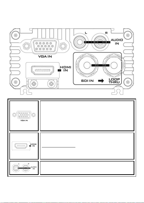
VGA IN
VGA IN connects the VGA equipment.
Supported Resolutions
800x600@60Hz, 1024x768@60Hz, 1280x1024@60Hz
1366x768@60Hz, 1400x1050@60Hz, 1600x1200@60Hz
1280x720@60Hz, 1920x1080@60Hz
HDMI IN
HDMI IN connects the HDMI equipment.
HDCP Copy Protection
For legal reasons, the HDMI input is unable to pass on
video from copy protected HDMI sources.
Audio IN
Inputs for 2 channels of RCA unbalanced audio
Front Panel
Page 10

10
HD-SDI IN & Output (Loop Thru)
HD-SDI input and loop-through output connectors.
Left BNC connector: HD/SD-SDI Input
Right BNC connector: Loop Thru Output
Mode Select (DIP switch)
Use the DIP switch to manually set the DAC-70 modes;
please refer to the DIP Switch Mode Selection section for
details.
Source Indicator
Indicates video source format.
HDMI OUT
HDMI Video and Audio output.
Rear Panel
Page 11

11
HD/SD - SDI OUT
SDI Video and Audio output.
DC IN Socket
Connects the supplied 12V PSU to this socket. The
connection can be secured by screwing the outer fastening
ring of the DC IN plug to the socket.
USB
The USB port connects the DAC-70 to the PC for Firmware
upgrade and access to the DAC-70 Center Utility.
Page 12

12
3. DIP Switch Mode Selection
DIP SW 8
Aspect Ratio
Full
Screen
Pan Scan
16:9 / Keep
Aspect
Ratio (1:1)
Select “Pan Scan
16:9” or “Keep
Aspect Ratio” (1:1)
on the DAC-70
Center Utility.
Please refer to the
next page for
details.
0
1
DIP SW 4/5/6/7
Video Output
0000 1920x1080 p60
0001 1920x1080 p59.94
0010 1920x1080 p50
0011 1920x1080 p30
0100 1920x1080 p29.97
0101 1920x1080 p25
0110 1920x1080 p24
0111 1920x1080 p23.98
1000 1920x1080 i60
1001 1920x1080 i59.94
1010 1920x1080 i50
1011 1280x720 p60
1100 1280x720 p59.94
1101 1280x720 p50
1110 720x480 i59 (525i)
1111 720x570 i50 (625i)
DIP SW 3
Audio
0 INT.
1 EXT.
DIP Switch is disabled when
SOURCE is set to 11.
DIP SW 1/2
Source
00 VGA
01 HDMI
10 SDI
11 PC
Page 13

13
DIP Switch PIN 8
0
Full Screen
1
Pan Scan 16:9 / Keep Aspect Ratio (1:1)
On the MAIN page of the DAC-70 Center Utility, click the Setting tab
to enter the page on which the user is allowed to select “Pan Scan
16:9” or “Keep Aspect Ratio” (1:1). Reboot the device after setting.
Input 4:3 / Output 16:9
Input 16:9 / Output 4:3
PAN SCAN 16:9
If the Pan Scan 16:9 mode is selected, the table below provides an illustration
as to how the image will be displayed on the 16:9 and 4:3 monitors given that
their respective input aspect ratios are 4:3 and 16:9.
Page 14

14
4. DAC-70 Center Utility
DAC-70 Center Utility is a Graphical User Interface that allows the user to
obtain the device information and perform various video and audio settings.
To use the utility, the user should first copy the DAC-70 Center.exe utility
software from the installation CD to the computer running Windows. After
that, connect the DAC-70 to the same computer using the USB cable. Switch
on the DAC-70 and open the DAC-70 Center Utility software.
Information
Click the Information tab to obtain the information on input format and
firmware version.
Page 15

15
Video
Click the Video tab to enter the video setup page.
On the video setup page, click the Video Setting button to enter the video
configuration page.
Page 16

16
Set the input source, aspect ratio and output format.
Click Next Page
Page 17

17
Set the HDMI Output Colour, HDMI Output Range and Edge Enhance.
Note 1: When “Input Source” is
set to “VGA“, the user will be
allowed to adjust “ Horizontal
Position” and “Vertical Position”
in the Image Adjust.
Note 2: When “Aspect Ratio” is
set to “Under Scan“, the user will
be allowed to adjust “Horizontal
Size” and “Vertical Size ” in the
Image Adjust.
Enable 3G Level B if your video resolution is 1080p50/59.94/60.
Click Apply after all settings are configured.
Page 18

18
Audio
Click the Audio tab to set audio parameters.
Click Apply after setting Audio Mute, Audio Source and Audio Level.
Note 1: Audio Level allows the user to select between EBU and SMPTE standards.
Note 2: Audio Level setting is enabled only for RCA input.
Page 19

19
Picture
Click the Proc AMP tab to adjust the picture settings.
Set the Brightness, Contrast, Hue, and Saturation levels on the Proc Amp
setup page.
Page 20

20
Setting
To restore the factory default settings, click the Setting tab.
Click the Factory Default button to reset the DAC-70 to factory defaults.
Page 21

21
In addition, the user can also set Dip Switch 8 (1) Mode, OSD Hide Mode and
Dip Switch 8 (1) Mode
When 8th bit of the DIP switch is set to 1, this
option allows the user to select Pan Scan 16:9 or
Keep Aspect Ratio (1:1).
OSD Hide Mode
When enabled, source information and output
resolution will not be displayed on the
information page upon resolution change.
No Signal Mode
This sets how the screen looks like when there is
no signal.
No Signal Mode.
Page 22

22
5. Format Conversion
The DAC-70 allows users to up-convert, down-convert and cross-convert
between different resolutions and I/O interfaces. See the table below for
details.
Page 23

23
6. Firmware Update
From time to time Datavideo may release new firmware to either add new
features or fix reported bugs in the current DAC-70 firmware. Customers can
update the DAC-70 firmware themselves or contact their local dealer for
assistance.
This section describes the firmware update process and it should take
approximately 10 minutes of total time to complete. Please note the
current DAC-70 settings. T he update process should not be interrupted
once started as this could result in a non-responsive unit.
A working DAC-70 requires the following:
1. The latest firmware file for the DAC-70. This can be obtained from your
local Datavideo dealer or office.
2. The Upload Firmware utility. This can also be obtained from your local
Datavideo dealer or office.
3. A Windows PC with USB 2.0 port.
4. A USB A to micro USB cable (USB 2.0).
How to update the DAC-70 firmware
1. Switch off the DAC-70 power.
2. Save the latest firmware file and the
Upload Firmware utility to the PC desktop.
3. Use USB 2.0 cable to connect the DAC-70 to the computer.
4. Open the Datavideo Upload Firmware utility, which will show
Disconnected and the connect button is greyed
5. Switch on the DAC-70 power and the connect button will now be enabled.
Click the connect button and the Utility will show Connected.
6. Click the Open File button and select the new firmware file.
7. Click the Start button and wait for the progress bar to finish.
8. After the update is finished, the utility will show PASS to confirm that the
unit has been updated successfully.
9. The utility will automatically disconnect the DAC-70 unit.
10. Unplug the USB cable from the DAC-70 and power cycle the unit.
11. The updated DAC-70 is now ready for use.
out.
Page 24

24
7. Dimensions
All measurements in millimeters (mm)
Page 25

8. Specifications
Input
VGA x 1
HDMI x 1
HD/SD-SDI x 1
Analog Audio L/R
Output
SDI x 2
HDMI x 1
SDI Loop thru BNC (front panel)
Micro USB
Firmware upgrade
Aspect ratio mode selection
Video Input
Format
SDI (YUV)
1080p60/59.94/50, 1080p30/29.97/25/24/23.98
1080psf30/29.97/25/24/23.98
1080i60/59.94/50, , 720p60/59.94/50
525i, 625i
HDMI (YUV / RGB)
1080p60/59.94/50, 1080p30/29.97/25/24/23.98
1080psf30/29.97/25/24/23.98
1080i60/59.94/50, 720p60/59.94/50
480p, 576p, 480i, 576i
800x600@60Hz, 1024x768@60Hz, 1280x1024@60Hz
1366x768@60Hz, 1400x1050@60Hz,
1600x1200@60Hz
VGA (RGB)
800x600@60Hz, 1024x768@60Hz, 1280x1024@60Hz
1366x768@60Hz, 1400x1050@60Hz,
1600x1200@60Hz
1280x720@60Hz, 1920x1080@60Hz
Video Output
Format
SDI / HDMI
1080p60/59.94/50, 1080p30/29.97/25/24/23.98
1080i60/59.94/50, 720p60/59.94/50
525i, 625i
25
Page 26

26
Audio Format
Input
Analog Audio L/R : stereo audio
SDI / HDMI embedded audio up to 8CH, 48KHz, PCM
audio HDMI embedded audio up to 8CH,
44.1/48/96KHz, PCM audio
Output
SDI embedded audio up to 8CH, 48KHz, PCM audio
HDMI embedded audio up to 8CH, 48KHz, PCM audio
Operating
Temperature
0~40°C [32~104°F]
Storage
Temperature
-10~ +60°C
Dimensions
144.8mm(L) x 85mm(W) x 45.2mm(H)
Certifications
CE/FCC
Page 27

27
Notes
Page 28

https://www.datavideo.com/product/DAC-70
Datavideo Technologies Co., Ltd. All rights reserved 2020
Dec-11.2019 Ver:E9
 Loading...