

Page 1
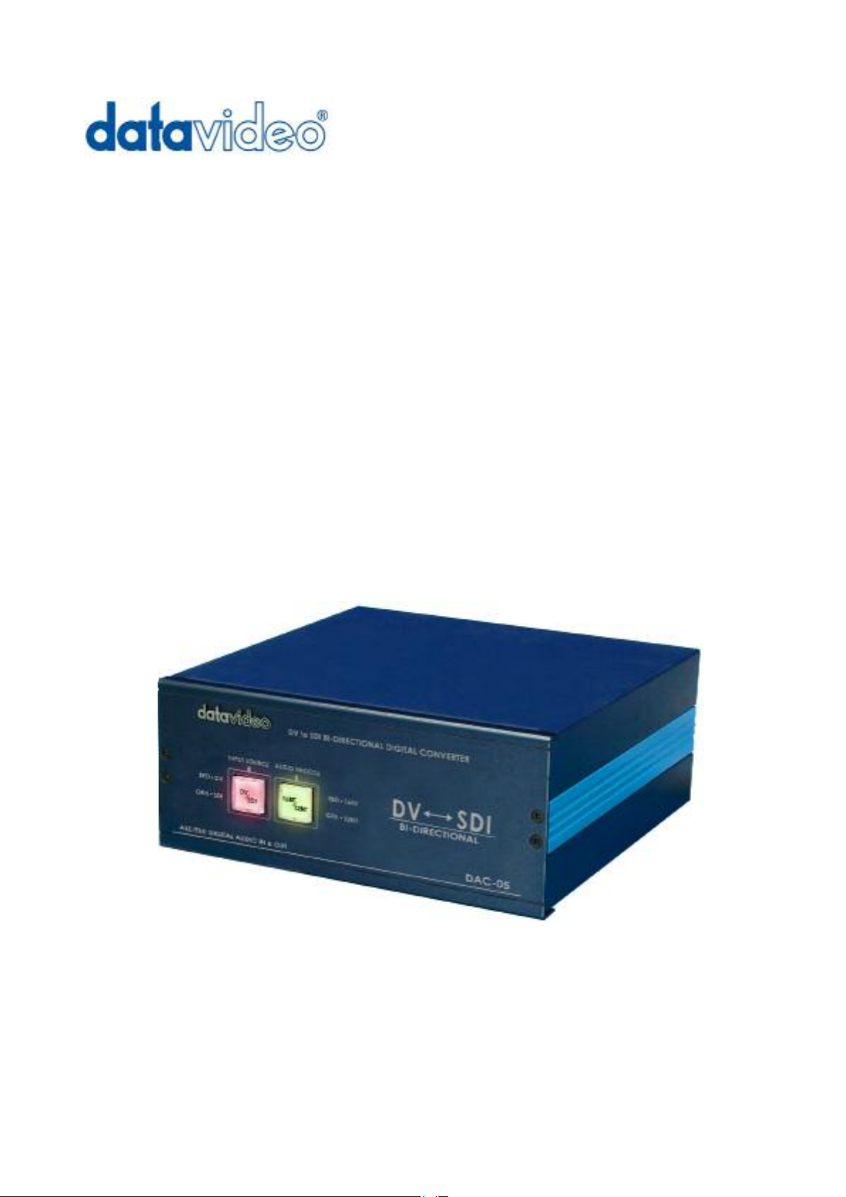
Bi-Directional
SDI to DV Converter
DAC-5
User’s Guide
http://www.datavideo-tek.com
Page 2

Table of contents
Warnings and Precautions --------------------------------------------------------------- 2
Warranty and Tech support -------------------------------------------------------------- 3
Introduction ---------------------------------------------------------------------------------- 4
Features -------------------------------------------------------------------------------------- 5
Installation ------------------------------------------------------------------------------------ 6
Editing with a DV NLE System and a DVCPRO Studio Editing VTR---- 7
Transferring from DV to SDI+AES------------------------------------------------ 8
Transferring from SDI+AES to DV ------------------------------------------------ 9
Transferring from DV to Betacam Deck --------------------------------------- 10
Operation ------------------------------------------------------------------------------------11
Front Panel ---------------------------------------------------------------------------11
Rear Panel -------------------------------------------------------------------------- 12
Dip Switches for Mode setting ------------------------------------------------- 12
Specifications ----------------------------------------------------------------------------- 15
Trouble Shooting ------------------------------------------------------------------------- 16
1
Page 3

Warnings and Precautions
1. Read all of these warnings and save them for later reference.
2. Follow all warnings and instructions marked on this unit.
3. Unplug this unit from the wall outlet before cleaning. Do not use liquid or aerosol cleaners. Use a
damp cloth for cleaning.
4. Do not use this unit in or near water.
5. Do not place this unit on an unstable cart, stand, or table. The unit may fall, causing serious
damage.
6. Slots and openings on the cabinet top, back, and bottom are provided for ventilation. To ensure
safe and reliable operation of this unit, and to protect it from overheating, do not block or cover
these openings. Do not place this unit on a bed, sofa, rug, or similar surface, as the ventilation
openings on the bottom of the cabinet will be blocked. This unit should never be placed near or
over a heat register or radiator. This unit should not be placed in a built-in installation unless
proper ventilation is provided.
7. This product should only be operated from the type of power source indicated on the marking label
of the AC adapter. If you are not sure of the type of power available, consult your Datavideo dealer
or your local power company.
8. Do not allow anything to rest on the power cord. Do not locate this unit where the power cord will
be walked on, rolled over, or otherwise stressed.
9. If an extension cord must be used with this unit, make sure that the total of the ampere ratings on
the products plugged into the extension cord do not exceed the extension cord’s rating.
10. Make sure that the total amperes of all the units that are plugged into a single wall outlet do not
exceed 15 amperes.
11. Never push objects of any kind into this unit through the cabinet ventilation slots, as they may
touch dangerous voltage points or short out parts that could result in risk of fire or electric shock.
Never spill liquid of any kind onto or into this unit.
12. Except as specifically explained elsewhere in this manual, do not attempt to service this product
yourself. Opening or removing covers that are marked “Do Not Remove” may expose you to
dangerous voltage points or other risks, and will void your warranty. Refer all service issues to
qualified service personnel.
13. Unplug this product from the wall outlet and refer to qualified service personnel under the following
conditions:
a. When the power cord is damaged or frayed;
b. When liquid has spilled into the unit;
c. When the product has been exposed to rain or water;
d. When the product does not operate normally under normal operating conditions. Adjust
only those controls that are covered by the operating instructions in this manual; improper
adjustment of other controls may result in damage to the unit and may often require
extensive work by a qualified technician to restore the unit to normal operation;
e. When the product has been dropped or the cabinet has been damaged;
f. When the product exhibits a distinct change in performance, indicating a need for service.
2
Page 4

Warranty and Tech support
Datavideo warrants that the equipment it manufactures shall be free from defects in material and
workmanship for a period of 12 months from the date of product purchased. If equipment fails due to such
defects, Datavideo will, at its option, repair or provide a replacement for the defective part or product.
Equipment that fails after the warranty period, has been operated or installed in a manner other than that
specified by Datavideo, or has been subjected to abuse or modification, will be repaired for time and
material charges at the Buyer’s expense.
All out-of-warranty repairs are warranted for a period of ninety days (90) from the date of shipment from the
factory.
Datavideo maintains six offices worldwide to support this and other products.
Datavideo Corporation (USA)
12300-U East Washington Blvd., Whittier, CA 90606 USA
Tel: +1 562 696 2324 www.datavideo.us
Datavideo Technologies Europe BV
Californiedreef 263565 BL Utrecht, The Netherlands
Tel: +31 30 261 9656 www.datavideo.info
Datavideo UK Limited
Unit 2 Waterside Business Park, Hadfield, Glossop, Derbyshire SK131BE UK
Tel: +44 1457 851000 www.datavideo.info
Datavideo Technologies Co., Ltd.
10F, 176 Jian-Yi Rd, Chung Ho City, Taipei Hsien, Taiwan 235
Tel: +886 2 8227 2888 www.datavideo.com.tw
Datavideo Technologies China Co.
2F-D, 2 Lane 777, West Guangzhong Rd, Zhabei District, Shanghai, China
Tel: +86 21 5603 6599 www.datavideo.cn
Datavideo Technologies (S) PTE Ltd.
100 Lor 23, Geylang Rd, #01-03 D’Centennial, Singapore 388398
Tel: +65 6749 6866 www.datavideo.sg
3
Page 5

Introduction
DAC-5 is designed to convert SDI video and AES/EBU audio to and from compressed DV audio/video. It
encodes SDI, AES/EBU digital Audio to the DV format and sends the DV stream on the IEEE-1394
interface and it decodes the DV stream arriving on the IEEE-1394 interface and converts it to SDI and
AES/EBU Digital Audio output.
Features Video/Audio output of component YUV, Y/C, composite video and unbalanced stereo audio for
monitoring.
What’s in the Package
Item Description Q’ty
1 DAC-5 unit 1
2 1.2M BNC to BNC 4
3 30 cm Cable adaptor D-Sub 15 Pin to BNC-Male x 2 1
4 1.2m Y/C Cable s-plug to s-plug 1
5 Stereo Audio RCA 2R to 2R 1
6 IEEE 1394 6Pin to 4Pin + 2 Core 1.8m 1
7 IEEE 1394 6Pin to 6Pin Cable 1.8M 1
8 AC cord 1
9 Switching Adaptor 12V / 2.0A 1
10
User’s Guide 1
Features
- Bi-directional DV to SDI/AES-3id converter
- SDI video compliant with SMPTE 259M standard at 270Mbps Data transfer rate
- Encodes 4:2:2 SDI video and AES-3id audio to DV stream
- Decodes DV stream to 4:2:2 (SDI) video and AES-3id digital audio
- Dual IEEE-1394 6-pin FireWire (iLink) I/O ports. Available in DV25 NTSC 4:1:1/ PAL 4:2:0 format
- AES-3id audio input and output for interconnection with professional audio equipments
- Convenient NTSC/PAL Component YUV, Y/C, composite Video and analog audio outputs for
monitoring and backup recording
- Selectable PAL/NTSC video system
- Locked or Unlocked DV audio and 12-bit/16bit audio encode mode selectable
- Fully compatible with existing Operating System software of Windows 98, ME, XP, 2000 and MAC OS
and hardware for DV/i.Link processing
4
Page 6

Installation
Connection:
1 DV In/Out
Connect a DV source to one of the DV connectors at the rear of the DAC-5 for input and output. Source
must comply with IEEE-1394 (i.Link) standard. Two 6-pin DV connectors effectively provide active
loop-through when the unit is turned on.
2 SDI In/Out
Connect an SDI signal to the SDI input BNC connector (left-hand side) labeled SDI. The DAC-5 accepts
4:2:2 serial digital video signals in either 525 or 625 line formats. The input signal must conform to the
SMPTE 259M standard. Connect destination equipment to the SDI output BNC connector (right-hand side).
The DVITC timecode in the output signal respects the same standard as the one in the input signal.
3 AES In/Out
Connect an unbalanced AES signal to the AES input BNC connector labeled AES. DAC-5 supports 48 kHz
digital audio sample rates. This signal must comply with the AES-3id-1995 (SMPTE 276M) standard.
Connect destination equipment to the AES output BNC connector.
4 Monitoring Output
Connect analog destination equipment to the connectors at the rear of the DAC-5. Use the BNC labeled
Composite or the mini-Din labeled S-Video for video output; use the two RCA labeled R and L for audio
output.
5
Page 7

Application Examples
The following figures show typical set-ups for using the DAC-5.
Figure 1. Editing with a DV NLE System and a DV Cam Studio Editing VTR
Non-Linear Editing System
Broadcast
Monitor
DAC-5 Rear Panel
SDI
Digital Betacam
AES Source
6
Page 8

The following figures show typical set-ups for using the DAC-5.
Figure 2. Transferring from DV to SDI+AES
DV Camcorder
OR
DV VTR
OR
Non-Linear
Editing System
Video Source
Broadcast
DAC-5 Rear Panel
Digital Betacam
Monitor
SDI
AES Destination
7
Page 9

The following figures show typical set-ups for using the DAC-5.
Figure 3. Transferring from SDI+AES to DV
DV Camcorder
OR
DV VTR
OR
Broadcast
Monitor
Non-Linear
Editing System
DAC-5 Rear Panel
SDI
Digital Betacam
Video Source
8
AES Input
Page 10

The following figures show typical set-ups for using the DAC-5.
XLR Balanced Audio
Figure 4. Transferring from DV to Betacam Deck
DV Camcorder
OR
DV VTR
OR
Non-Linear
Editing System
Video Source
DAC-5 Rear Panel
Y.U.V Output
to Betacam
BAC-03
Betacam Deck
Broadcast
Monitor
9
Page 11

Operation: Front Panel
Select Video Input source SDI or DV Input
Select 16 Bit or 12 Bit DV Audio Encode
Select the DV audio encoding frequency.
10
Page 12

Operation: Rear Panel
NTSC
Dip Switches for Mode setting:
*. Note1:Mode DIP switch (Reboot the DAC-5 if you change a DIP Switch)
S1. PAL or NTSC (PAL-ON, NTSC-OFF)
S2. PAL: Select DV-25 PAL 4:2:0
NTSC: 7.5 IRE / 0 IRE (0 IRE-ON, 7.5 IRE-OFF)
ON
PAL
S1
OFF
*. Note: NTSC 0 IRE is most often used in Japan. 7.5 IRE is used elsewhere.
S3. DV Locked/Unlocked Audio Mode
S3 -- OFF: Locked Audio
S3 – ON: Unlocked Audio (factory default)
S4 & S5 for NTSC and PAL video system
ON
S4
S5
OFF S4
S2
OFF Reserved
ON 0 IRE
S2
OFF
7.5 IRE
ON MAC OS
Windows 2000 and Windows 98
OFF
ON Windows XP and Windows ME (Factory default)
OFF Camera Mode
DV25 4:2:0
ON
S6. Factory setting (OFF), please do not change.
11
Page 13

Dual IEEE-1394 6-pin FireWire (iLink) I/O ports:
Available in DV25 NTSC 4:1:1 or PAL 4:2:0 format
Please Note: As long as DAC-5 is connected to a PC thru one of the
IEEE1394 port, PC will disable the loop thru function and work only
peer to peer in between DAC-5 & PC.
Analog Video Out for Monitoring
Monitor your video in composite, Component or S–Video.
Analog: Component Video Y, U, V with Black Burst output
Analog Audio Out for Monitoring:
There are two channels unbalanced Audio output (RCA connectors
Left and Right.
SDI Digital Video Input and Output
4:2:2 Video SMPTE 259 M-C standard at 270 Mbps
12
Page 14

Pin assignment
Pin 1 Reserved
Pin 2 Reserved
Pin 3 BNC in (signal)
AES/EBU Digital Audio Input and output
Two channels AES/EBU Ch1/Ch2 In and Out thru the D–Sub 15 pin to
BNC adaptor. Please refer to the pin assignment below.
AES-3id unbalanced Audio Cable adaptor ch1 / ch2
In and Out
AES-3id cable adaptor, connecting D-Sub 15 Pin to unbalanced 75
Ohm BNC connectors
Pin 4 Reserved
Pin 5 Reserved
Pin 6 Ground
Pin 7 Ground
Pin 8 BNC in ground
Pin 9 BNC out ground
Pin 10 Ground
Pin 11 Reserved
Pin 12 Reserved
Pin 13 BNC out (signal)
Pin 14 Reserved
Pin 15 Reserved
13
Page 15

Specifications
Selectable Video Standards
NTSC/PAL
DV Input/Output
Two 6-PIN IEEE1394 Fire Wire Ports
Support NTSC 4:1:1, DV25 PAL 4:2:0
SDI Input/Output
Two BNC Connectors
Support 4:2:2 Video SMPTE 259 M-C
standard at 270 Mbps
Cables length up to 250 meter
Return Loss > 15 dB
Digital Audio Input/Output
Two Channels AES-3id (SMPTE 276M) BNC
connectors
Impedance: 75 ohm, unbalanced
Level: 1.0Vp-p
Sample rate: 48KHz
DV Locked / Unlocked Audio
2-Channel Locked / Unlocked Option
Analog Video out
NTSC (525/60) SMPTE 170M
PAL (625/50) ITU-R BT.470-6
Composite, S-Video Y/C and Component
Return Loss >20dB Upto 5 MHz
Black Burst Out
BNC 75 ohm
Audio Monitoring
Stereo unbalanced line out
Level: 6 Vp-p
Bandwidth: 20HZ ~ 20KHZ
S/N Ratio: >60 dB, THD: <0.3%
Conversion Delay
DV to SDI mode: 1.5 frames
SDI to DV mode: 1.5 frames
Computers
Windows 98, ME, XP, 2000 and MAC OS
Dimensions / Weight
8” x 9.8” x 5.2”
203 mm x 249 mm x 132 mm
Weight 6 lbs / 2.8kg
Power Input
DC 12V, 1.5 Amp
Accessories (Included)
1.2 m BNC to BNC (4)
30 cm D-Sub 15 Pin to 2 x BNC-Male (1)
1.2m Y/C Cable S-plug to S-plug (1)
1.5m RCA 2R to 2R (1)
1.8m 6-4 Pin Cable (1)
1.8m 6-6 Pin Cable (1)
AC Cord (1)
14
12V, 2.0 A Switching Adaptor (1)
User’s Guide (1)
Page 16

Troubleshooting
1- When using some camcorder models as a DV source, the DV signal may be lost if
you try to unplug the iLink cable from the DAC-5 during the transmission. To recover
from this situation, turn the camcorder off and then on again.
2- Turn-on the DAC-5 before launching any editing software
3- Macintosh users will have some problems if they try to toggle the video format (525 to
625 or 625 to 525) in the same session; they will not be able to correctly process the
video sequences in the new format. The DAC-5 must be powered on and in the right
video format (even if no input signal is connected to the unit) before attempting to
start the computer and launch the editing software.
15
Page 17

All the trademarks are the properties of their respective owners.
Datavideo Technologies Co., Ltd. All rights reserved 2004
16
P/N:082060363E1
 Loading...