

Page 1
CG-100
Version 1.72 with USB Dongle
Rev 080410
Page 2

Warnings and Precautions
If you have purchased this CG-100 software with a Blackmagic
Design DeckLink Card please observe the ins tall precautions
supplied the DeckLink card.
It is also advisable to read any precautionary notes supplied with your
computer which relate to installing new hardware and software.
When installing new software on to a Windows XP or Vista machine it
is advisable to first create a System Restore Point, this will provide
a working machine to go back to, should anything go wrong during
the installation.
Details of how to create a System Restore Point can be found in
your PC instruction manual or on the Microsoft Website. Alternatively
you can approach your company I.T. support desk.
Please also see the EULA - End User Licence Agreement at the rear
of this manual.
2
Page 3

Contents
Warnings and Precautions ............................................................. 2
Packing List ...................................................................................... 6
Disposal ............................................................................................ 6
Warranty ................................ ........................................................... 7
Introduction ...................................................................................... 8
Product Overview ................................................................ 8
Features .............................................................................. 9
Minimum Requirements ................................................................ 10
CG-100 Interface ............................................................................ 12
System Set Up ............................................... ................................. 13
TV system selection .......................................................... 13
Difference between NTSC and PAL ................................... 13
Display mode 4:3 or 16:9 ................................................... 14
Setting the Video Standard ........................................................... 15
Set Margins ....................................................................... 15
Right to left reading ....................................................................... 16
Synchronize CG output, PLAY function ............................. 17
CG output with no video input ....... . ........... ......................... 18
External Key ................................................................................... 19
Enable [App] button ........................................................... 20
Language setting ............................................................... 20
GPI Trigger ..................................................................................... 21
Tools, Effects.................................................................................. 23
Files ................................................................................... 23
Pages ................................................................................ 24
Objects ............... ............................................................... 26
Layout Tools & Animation T ools .................................................. 27
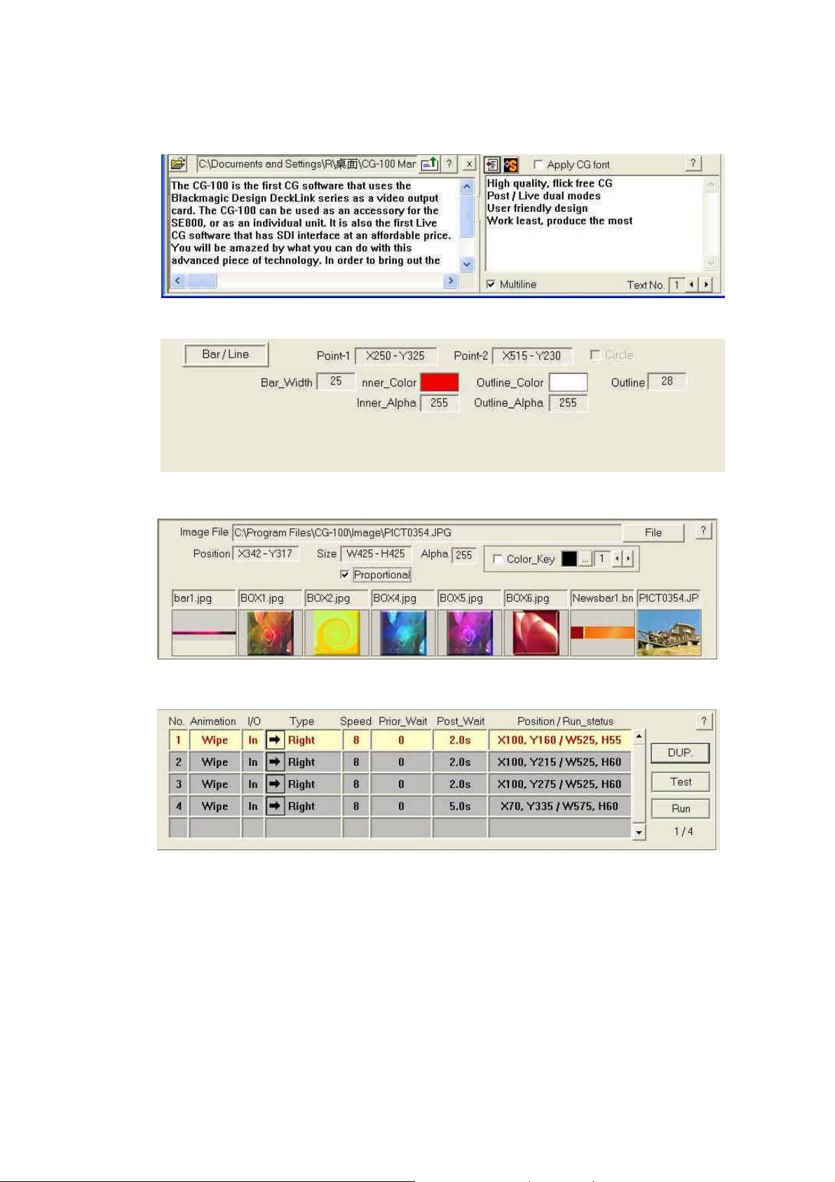
Parameter Panels .......................................................................... 28
Text Parameter Panel (1) ................................................... 28
Text Parameter Panel (2) or Saved Styles Panel ............... 28
Text Parameter Panel (3) or Mult i Line text ........................ 29
Graphic Parameter Panel .................................................. 29
Image Parameter Panel ..................................................... 29
Animation List .................................................................... 29
Layout Editing ................................................................................ 30
Text Editing ........................................................................ 30
How to Move a text object ................................................. 31
Fine tune the position of a Text Object ............................... 32
Resize a Text Object .......................................................... 32
Adjust the Gaps between letters (Kerning) ........................ 32
How to Rotate a Text Object .............................................. 33
Change the content of Text Objects ................................... 34
3
Page 4

Multi-line Text Objects ........................................................ 36
Saving Text S tyles ............................................................. 37
How to apply a Style to a Text Object ................................ 39
Returning to the Text Parameters Setting .......................... 39
The text parameters are: ............................................................... 40
Using the Mouse to set parameters ................................... 41
Vertical Text Objects (Asian fonts) ..................................... 41
Default width of a Letter or Character ................................ 41
Importing Text from a Text File ........................................... 42
Inserting a Graphic Bar or a Line ................................................. 43
Inserting a Rectangle or an Ellipse .............................................. 45
Parameters Panel for Rectangles and Ellipses .................. 46
Inserting an Image ......................................................................... 47
The transparency of an image ........................................... 49
Select an image colour to be transparent .......................... 50
Extra Editing Tools ........................................................................ 51
Group Move/Zoom ......................................................................... 53
Group Copy/Cut/Delete ................................................................. 57
Animation Editing .......................................................................... 58
Setting up an Animation Box .... .......................................... 58
Editing Ani mation Boxes .................................................... 60
To add a [Display] Animation ....................................................... 62
To add a [Wipe] animation ............................................................ 65
Select [Wipe] animation ..................................................... 65
Calculate Ani mation Time .................................................. 66
Prior Wait and Post Wait Time ........................................... 66
Trigger Animation with Keyboard (KB) ............................... 66
To add a [Push] animation ............................................................ 67
[WIPE] with Reserve Last screen ................................................. 68
[PUSH] with Reserve Last Screen................................................ 69
To add a [Fade] animation ............................................................ 70
Delete an existing animation line ................................................. 70
Change the order of animations .................................................. 70
Duplicate an Animation Line ........................................................ 71
Roll and Crawl ................................................................................ 71
To Roll a List ...................................................................... 71
Further settings of the Roll object panel ............................. 73
To adjust the size of a Roll Obje ct ...................................... 74
To adjust the size of a Crawl Object ............................................ 77
Live CG Editing .............................................................................. 78
Quick Edit function ........................................................................ 81
Modify the Text .................................................................. 81
Page List ........................................................................... 82
The effect of Reserve Last Screen ............................................... 83
4
Page 5

Reserve last screen ....................................................................... 84
Clean last screen ........................................................................... 85
Clipboard ........................................................................................ 86
Group copy to Clipboard .................................................... 86
Lock/Unlock the Clipboards ............................................... 87
Paste from the Clipboard ................................................... 87
LOGO .............................................................................................. 88
Clock & Stop Watch ....................................................................... 90
TARGA Sequences ........................................................................ 93
T ransfer Text to CG function ........................................................ 95
Number Tags for text objects ............................................. 97
Single Text Crawl Button .............................................................. 98
App Button ..................................................................................... 99
Logo Generator ................................................................. 99
Features of the Logo Generator ........................................ 99
What can you create in the Logo generator? ........................... 100
Where to set up the objects? (See Red boxes) ........................ 100
How to start the Logo Generator ............................................... 100
Logo Generator Screen Views ................................................... 101
Page View ....................................................................... 101
Layout View ..................................................................... 102
Page View Buttons and Settings ...................................... 103
Zoom before play ............................................................. 103
Logo Generator Background CG Pages .......................... 104
Red or Green Frames ...................................................... 104
Setting up a Sample Page ........................................................... 105
Creation of Text Crawl Samples ....................................... 106
Adding background CG Pages ........................................ 107
Adding a TV Channel’s Logo ........................................... 108
Adding a Targa Sequence .............. . ......... ......... . ......... .... 109
Crawl-A / Crawl-B Set Up ............................................................ 112
Commercial Break ........................................................... 1 1 3
CG Page Editor ............................................................................ 114
DL-Renderer ................................................................................. 116
Introduction ...................................................................... 1 16
Setting DL-Renderer ........................................................ 1 16
Bonus Utility of CG-100 .............................................................. 117
Live Streaming Software .................................................. 1 17
Trouble Shooting ......................................................................... 122
Frequently Asked Questions ...................................................... 123
CG-100 Registration .................................................................... 124
Datavideo End User License Agreement (EULA) ..................... 125
Service and Support .................................................................... 130
5
Page 6
Packing List
1. CG-100 software CD
2. CG-100 Security Dongle x1
3. CG-100 Installation Guide (PDF version)
4. CG-100 User Manual (PDF version)
Optional video card*
Blackmagic Design DeckLink SDI PCIe card
or
Blackmagic Design DeckLink Studio 2 PCIe card
* Please consult your dealer to confirm if these items should be present.
Disposal
For EU Customers only - WEEE Marking.
This symbol on the USB Dongle indicates that it
should not be treated as household waste. It must
be handed over to the applicable take-back
scheme for the recycling of waste electrical and
electronic equipment. For more detailed
information about the recycling of this product,
please contact yo ur lo ca l Datav ide o offic e.
6
Page 7

Warranty
Please also see the EULA - End User Licence Agreement at the rear
of this manual.
Standard Warranty
Datavideo equipment is guaranteed against any manufacturing
defects for one year from the date of purchase.
The original purch a se in v oic e or other documentary evid en c e shou ld
be supplied at the time of any request for repair under warranty.
Damage caused by accident, misuse, unauthorized repairs, sand, grit
or water is not covered by this warranty.
All mail or transportation costs including insurance are at the expense
of the owner.
All other claims of any nature are not covered.
Cables & batteries are not covered under warranty.
Warranty only valid within the country or region of purchase.
Your statut ory rights are not affected.
Two Year W arranty
All Datavideo products purchased after 01-Oct.-2008 qualify for a free
one year extension to the standard Warrant y, providing the product is
registered with Datavideo within 30 days of purchase. For information
on how to register please visit www.datavideo-tek.com or contact
your local Datavideo office or authorized Distributors.
Certain parts with limited lifetime expectancy such as LCD Panels,
DVD Drives, Hard Drives are only covered for the first 10,000 hours,
or 1 year (whichever comes first).
Any second year warranty claims must be made to your local
Datavideo office or one of its authorized Distributors before the
extended warranty expires.
7
Page 8

Introduction
Thank you for purchasing the Datavideo CG-100 Character
Generator PC soft ware. CG-100 is the first CG software that uses a
Blackmagic Design DeckLink card as a video output card. This PC
software and card set up can be used as an accessory DSK overlay
to Datavideo vision mixers such as the SE-800 or SE-900, or as an
individual unit.
It is also the first Live CG software for PC with an SDI inter face at an
affordable price. We hope you will be amazed by what you can do
with this product!
In order to get the maximum of this product, we recommend that you
spend some time reading this manual carefully to familiarize yourself
with its capabilities.
Product Overview
SDI overlay offers the best, broadcast quality, CG solution in the
industry today. However, it has always been beyond the budget of
small studios and production houses – Datavideo CG-100 has now
changed that!
The CG-100 combines with a Blackmagic Design DeckLink Card to
give you a live SD- SDI CG ov erlay at an afford able price.
It can be switched between NTSC and PAL video standards and is
able to generate graphics for either 16:9 or 4:3 aspect ratios.
Pages can be composed, saved to file an d combined with animation
effects, to run as a sequence, or they can be displayed and edited
live.
CG-100 combines perfectly with the SE-800 / SE-900 mixers to give
superb quality gr aphics / text / logo overlay on live production mixes.
CG-100 can be used with any SDI or YUV input switchers depending
on the connections of the DeckLink card used. It can also be used
with the SE-800 / SE-900 via their own SDI / CG DSK overlay
interfaces.
8
Page 9

Features
Import image objects as graphics and store them as part of a
page.
Simple shapes (bars, ellipses and rectangles) are menu items
and may be added to the page.
Animation objects can Wipe, Push, and Fade in various
directions at different speeds.
Text can roll and crawl.
Supports Windows Unicode for multi-language inputs and
fonts.
Redo/Undo funct i on s f o r quick testing of an additional effect.
Live editing mode provides gr eat f le xibility to immediately alt e r
one CG page while another CG page running is live.
Quick CG Text Editor allows navigation from page to page to
quickly modify text.
Stand-alone logo display function.
Nine items can be stored to the “clipboard” and used in CG
combinations on different pages and files.
Group function makes CG combinations easy to edit.
SDI available. (via DeckLink SDI or Studio PCIe cards).
YUV available. (via DeckLink Studio PCIe card).
Automatically create multiple CG pages from a text file.
Time & date display.
TARGA sequence playback.
GPI trigger animation.
App Button “Logo Generator” mode for live productions.
Plus bonus Live Streaming software*
* This software can only be used on a PC with Windows XP Professional 32bit OS
9
Page 10

Minimum Requirements
CPU:
Intel Pentium 4 (2.0 GHz) or higher
Operating System:
Microsoft Windows XP Professional (SP2) 32bit OS
or
Microsoft Windows Vista Business (SP1) 32bit OS
System RAM:
2GB or higher for Windows XP
or
4GB for Windows Vista Business
VGA resolution:
32-bit colour recommended VGA, XGA or higher
CG-100 requires a PC monitor resolution of 1024 x 768
Required Free Hard Drive Space:
150 MB (for CG-100 & DeckLink Driver)
Compatible PCIe cards:
Blackmagic Design DeckLink SDI card
or
Blackmagic Design DeckLink Studio 2 Card.
USB Port:
Computer needs 1 free USB 2.0 port for the CG-100 USB
Dongle
NOTE:
These system specifications may change, without notice, depending
upon the card used. Please consult your dealer for the latest ad vice.
For the latest information on Blackmagic Design Cards please visit:
http://www.blackmagic-design.com/support/
10
Page 11
QuickTime Recommendations
We have found that QuickTime™ 6.3 or later is fully compatible with
CG-100, DeckLink cards and their drivers.
If upgrading to the latest version of QuickTime™, you will need
to un-install and re-install the latest DeckLink drivers to regain full
functionality of the DeckLink card.
Additional information and downloads can be found using:
www.apple.com/quicktime/
For the latest information and drivers on Blackmagic Design Cards
please visit:
http://www.blackmagic-design.com/support/
11
Page 12
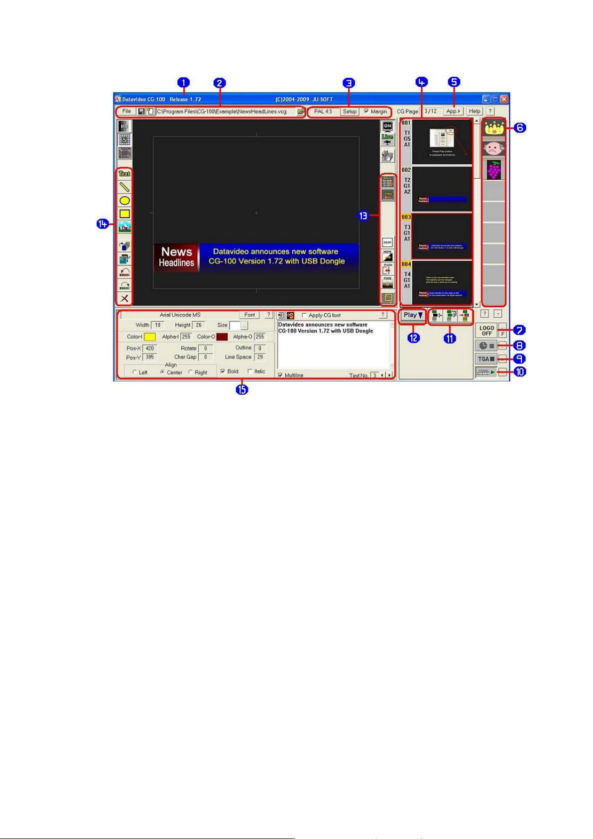
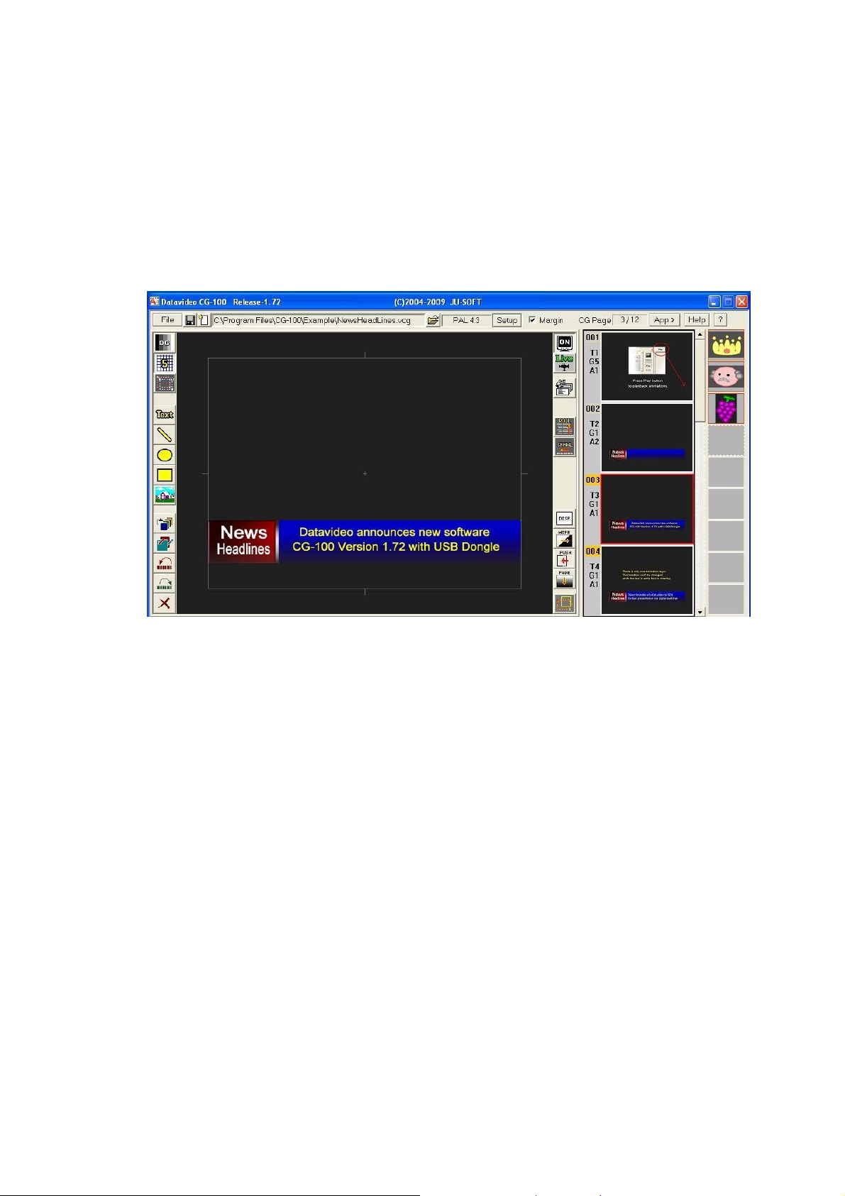
CG-100 Interface
r
1). CG-100 Version Information 9). Targa Sequence
2). File, Save, New & Open 10). Single Text Crawl Button
3). Screen Aspect, Set Up &
Margin
4). Page List & Information 12). Play or Stop Page Sequence
5). App Button / Logo Generato
6). Object Clipboard 14). Editing and Graphic Tools
7). Logo Management 15). Text & Graphic Management
8). Time & Date / Timer
Functions
11). Insert, Copy, Delete Page
13). Text Animation Controls
These are the basic function descriptions. For a more detailed
overview of each function, please read through the appropriate
section later in this manual.
12
Page 13
System Set Up
TV system selection
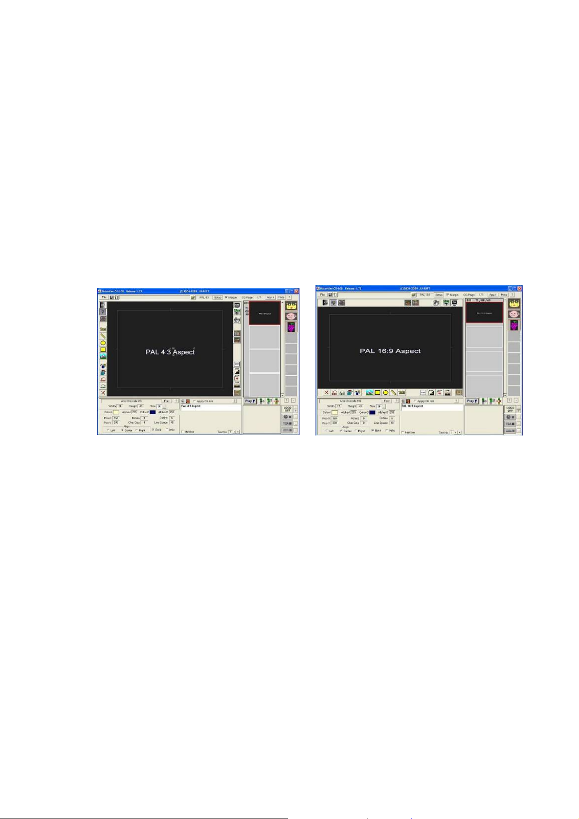
CG-100 can be set for either NTSC or PAL. It can also be set as
either 4:3 or 16:9. When choosing NTSC, the TV screen resolution is
720 x 486 pixels. When choosing PAL, the resolution will become 720
x 576 pixels. However, on the PC monitor, there is no difference
between PAL and NTSC, the screen aspect is just 4:3 or 16:9. When
using the CG-100, you must keep in mind that the pixels on the PC
monitor are not the same as on a TV. The following pictures show
how CG-100 looks when a 4:3 or 16:9 aspect is selected.
Difference between NTSC and PAL
Although the resolutions of NTSC (720x486) and PAL (720x576) are
different, the ratio of their widths and heights are the same.
If we use the idea of pixel co-ordinates (X and Y). Let us say that the
Y co-ordinate of
middle of the screen , as NTSC is 486 high. However, in PAL
would appear in a higher position, as PAL is 576 high. See the
examples on the next page.
Now, if Title B is placed at 440 on the Y axis it is near the bottom of a
PAL screen.
the same Y val u e 4 40 is used in an NTSC mode.
Title A is 243. In NTSC the height of Title A is in the
Title A
Title B would be lower, and outside the safe area when
13
Page 14
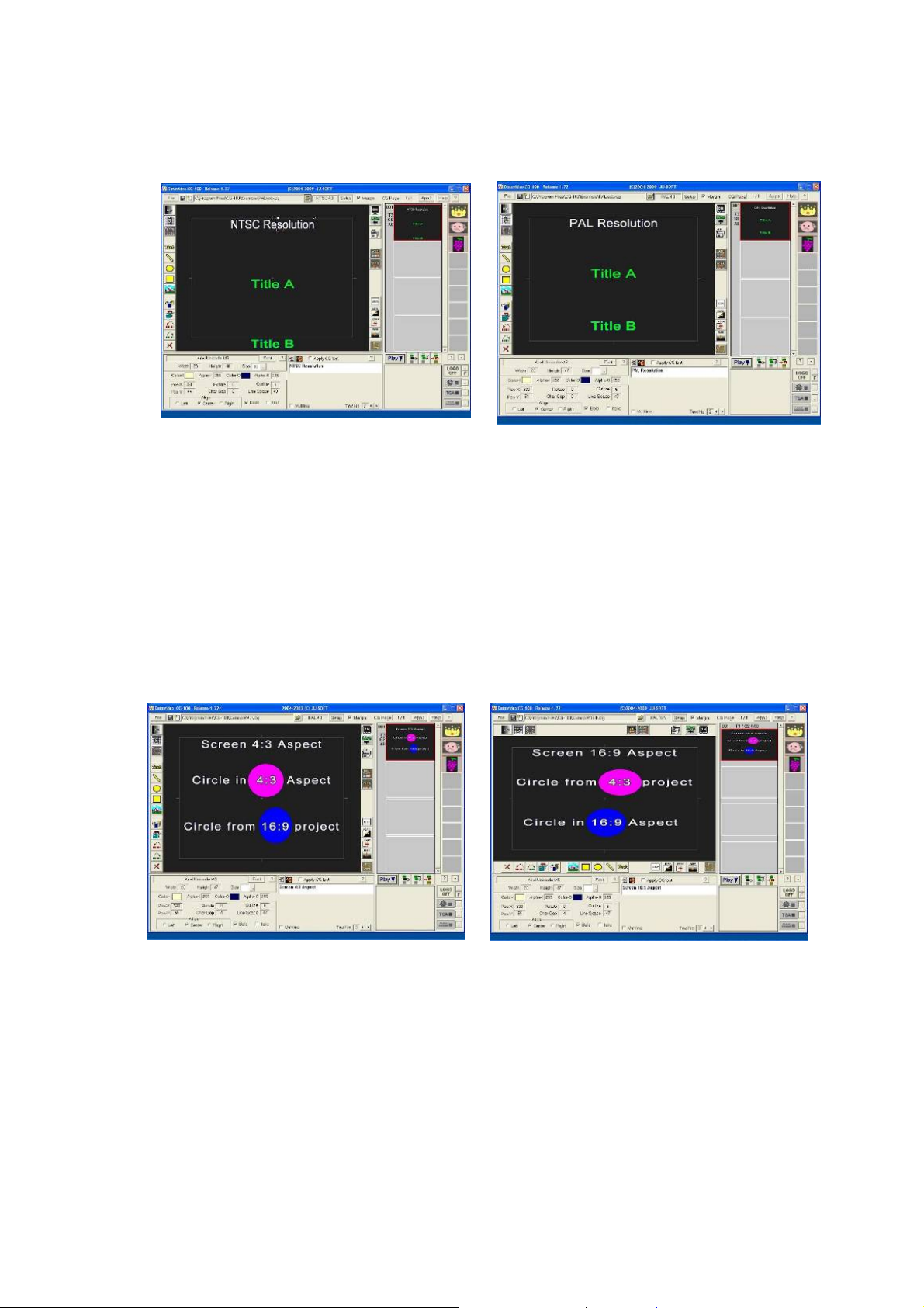
In NTSC mode Title A is in
the Middle of the sc r e en
Title B is outside the Safe
Area in NTSC mode
Title A is higher when the
screen is changed to PAL
Title B is within the Safe Area
in PAL mode
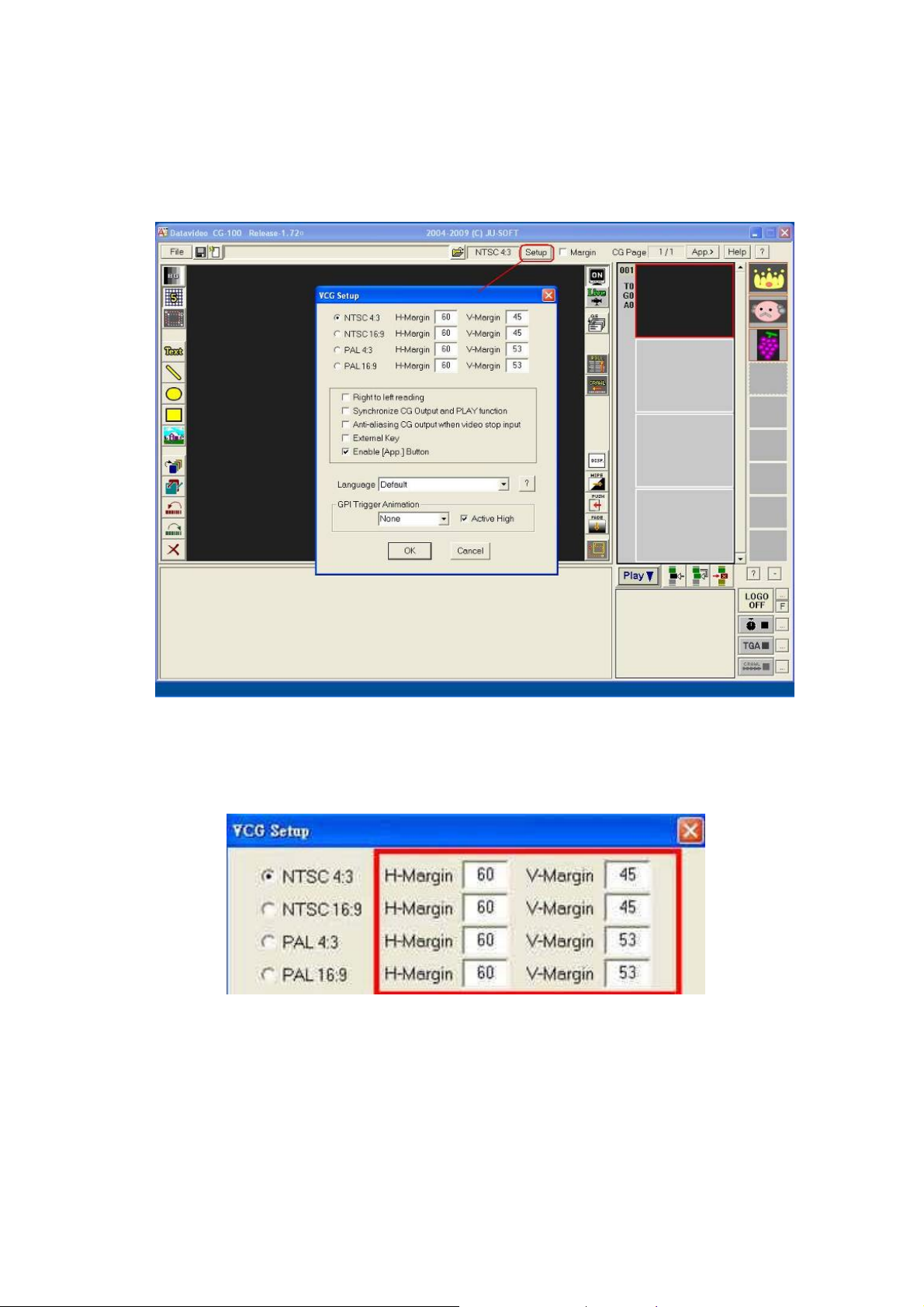
Display mode 4:3 or 16:9
Setting CG-100 mode from 4:3 to 16:9 will not change the resolution
of the PC monitor. Howev er, transferring a circle from a 4:3 project to
16:9 Aspect, will change its shape from a round circle to an ellipse
and vice versa. Please see the examples as below.
Top is a circle in 4:3
Bottom is a tall ellipse in 4:3
Top changes to an ellipse in 16:9
Bottom changes to a circle in 16:9
14
Page 15
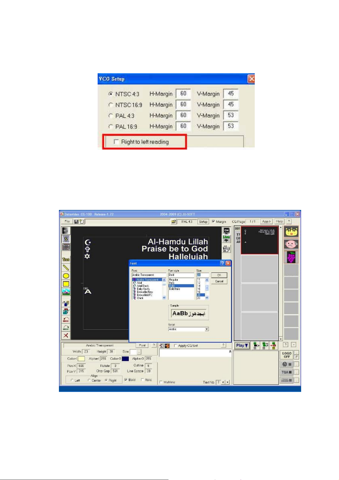
Setting the Video Standard
Go to SET UP, Click on the required video standard. The CG-100
Application needs to be re-started if changes have been made.
Set Margins
Type the pixels to be deducted for horizontal and vertical margins
15
Page 16
Right to left reading
CG-100 enables typing for Left to Right and Right to Left. For Right to
Left reading you need to tick the check box “Right to left reading”
Be aware that you need to select appropriate fonts, especially for
Hebrew or Arabic and to have
Right to Left reading selected . For
example a question mark “?” will be placed at the left side while
choosing Hebrew fonts.
16
Page 17
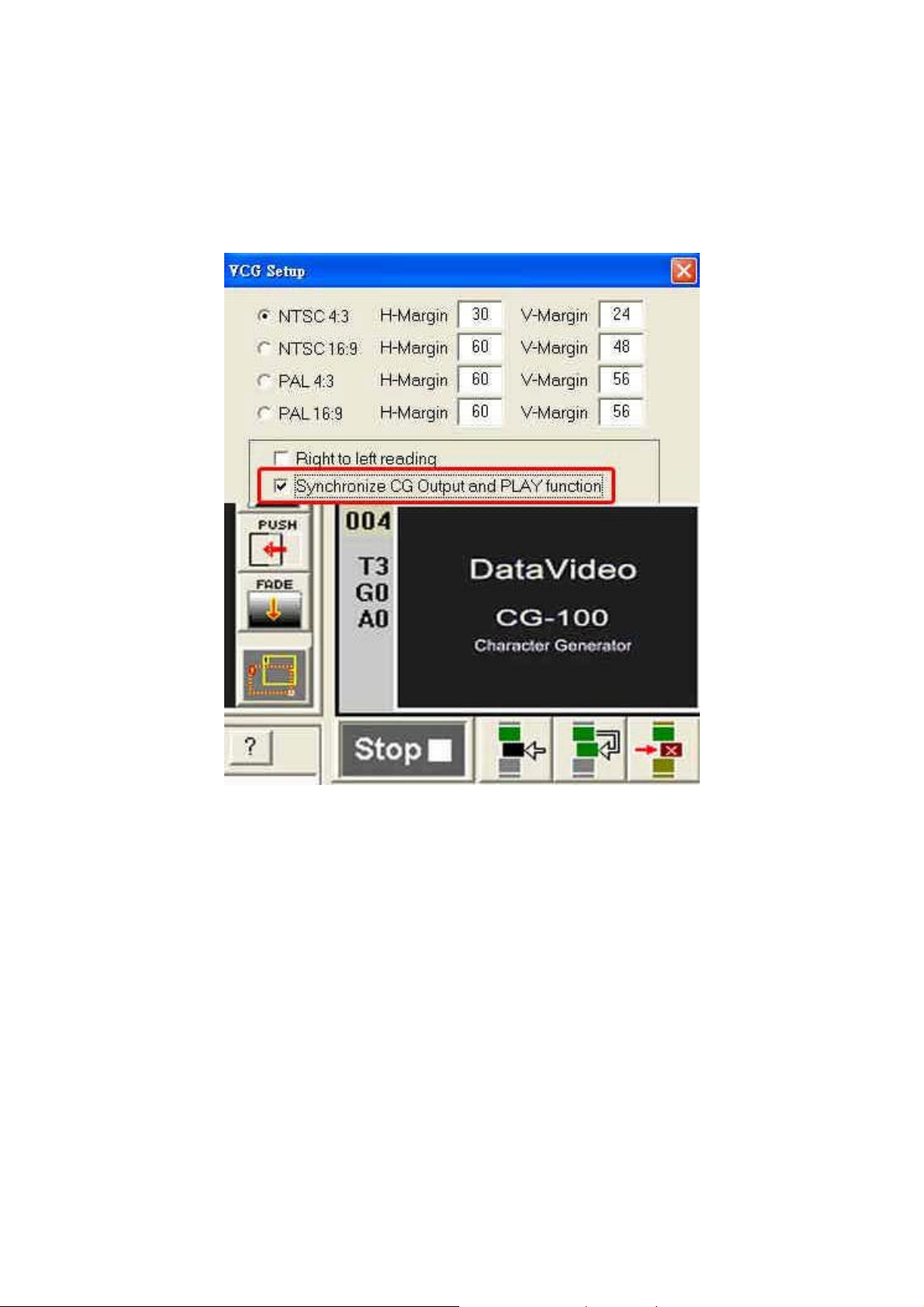
Synchronize CG output, PLAY function
This function needs to be enabled when using live CG mode. When
this selection has been ticked, the CG output will be cleared when
clicking stop.
i.e. it does not appear on the video out.
17
Page 18
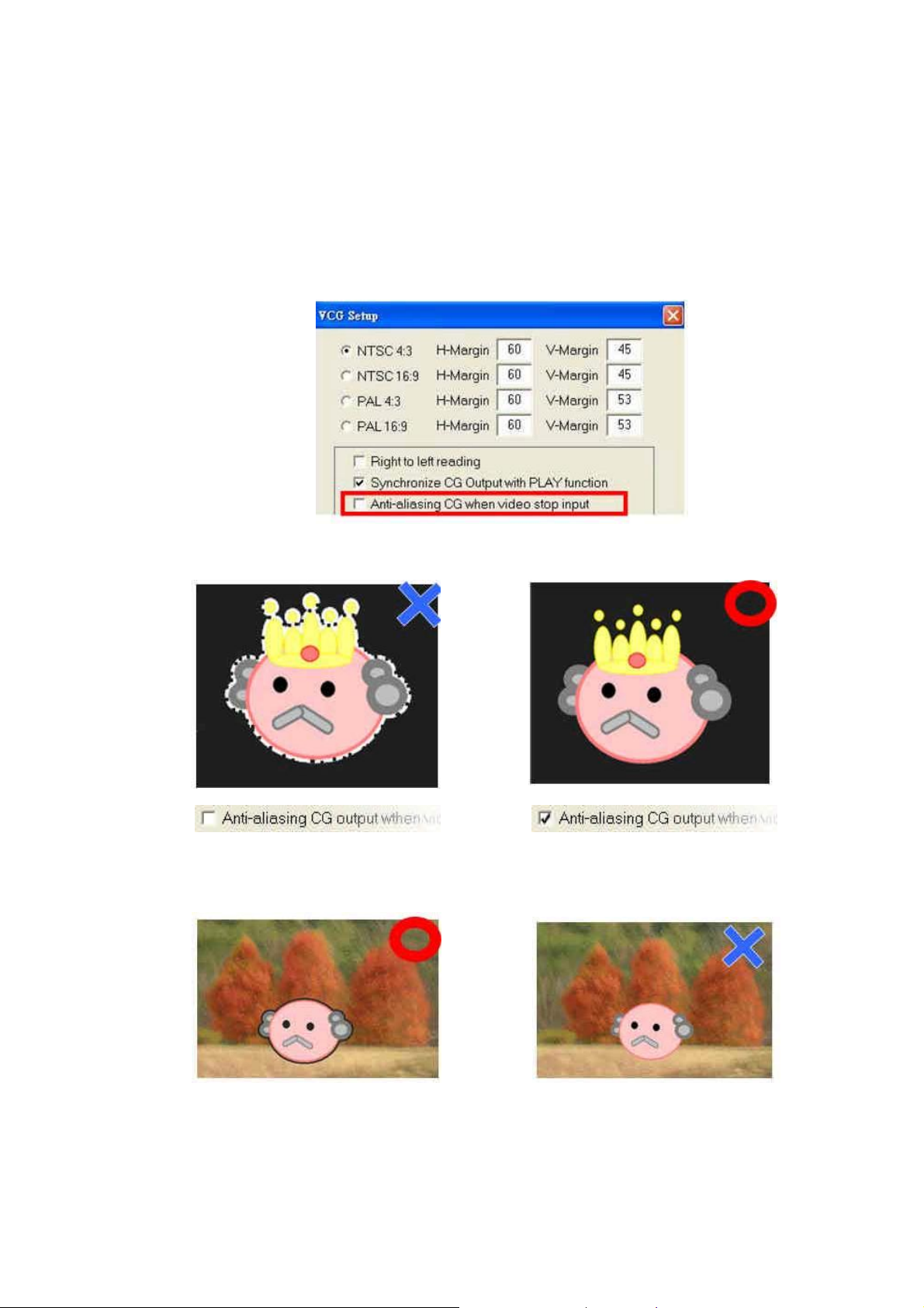
CG output with no video input
Anti-aliasing CG output when video stop input - This option is used if
there is no video being input, and you want to output the computer
graphics and text only on a black background just for presentation etc.
Remember: tick the check box: “Anti-aliasing CG output when
video stop input
” to ensure a good qualit y presentation output.
Without Video Input
However, if there is video being input, do not tick the check box.
18
Page 19
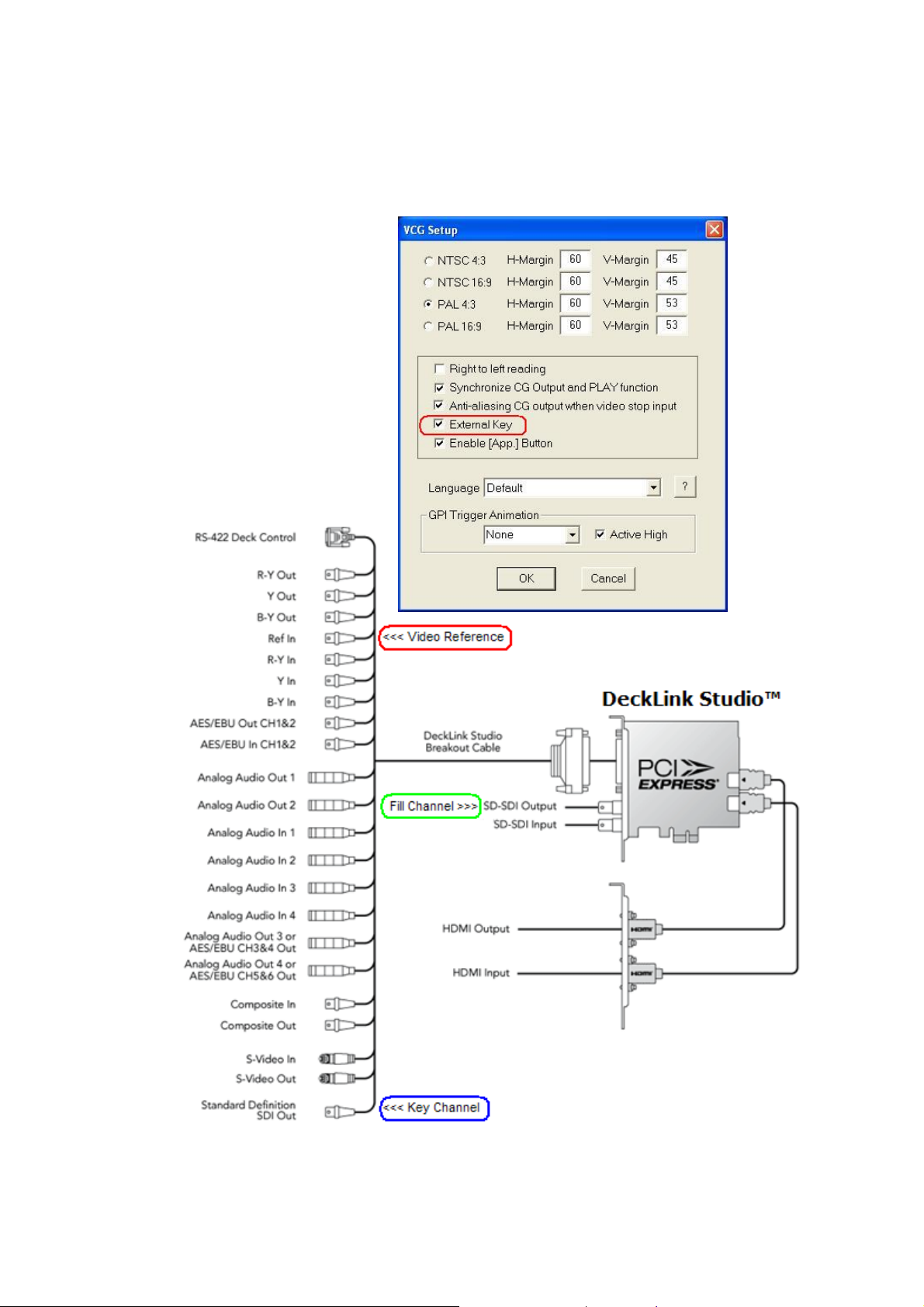
External Key
This function works with the DeckLink Studio Card. Tick the check
box: “External Key” So the Alpha Key output for Live Video and CG
output can be merged externally in another device / mixer.
19
Page 20
Enable [App] button
To enable a special logo generator plug-in application of CG-100,
please go to SETUP window and tick “Enable [App] button”. If you do
not want this plug in, remove the tick so that the App. Button box is
empty.
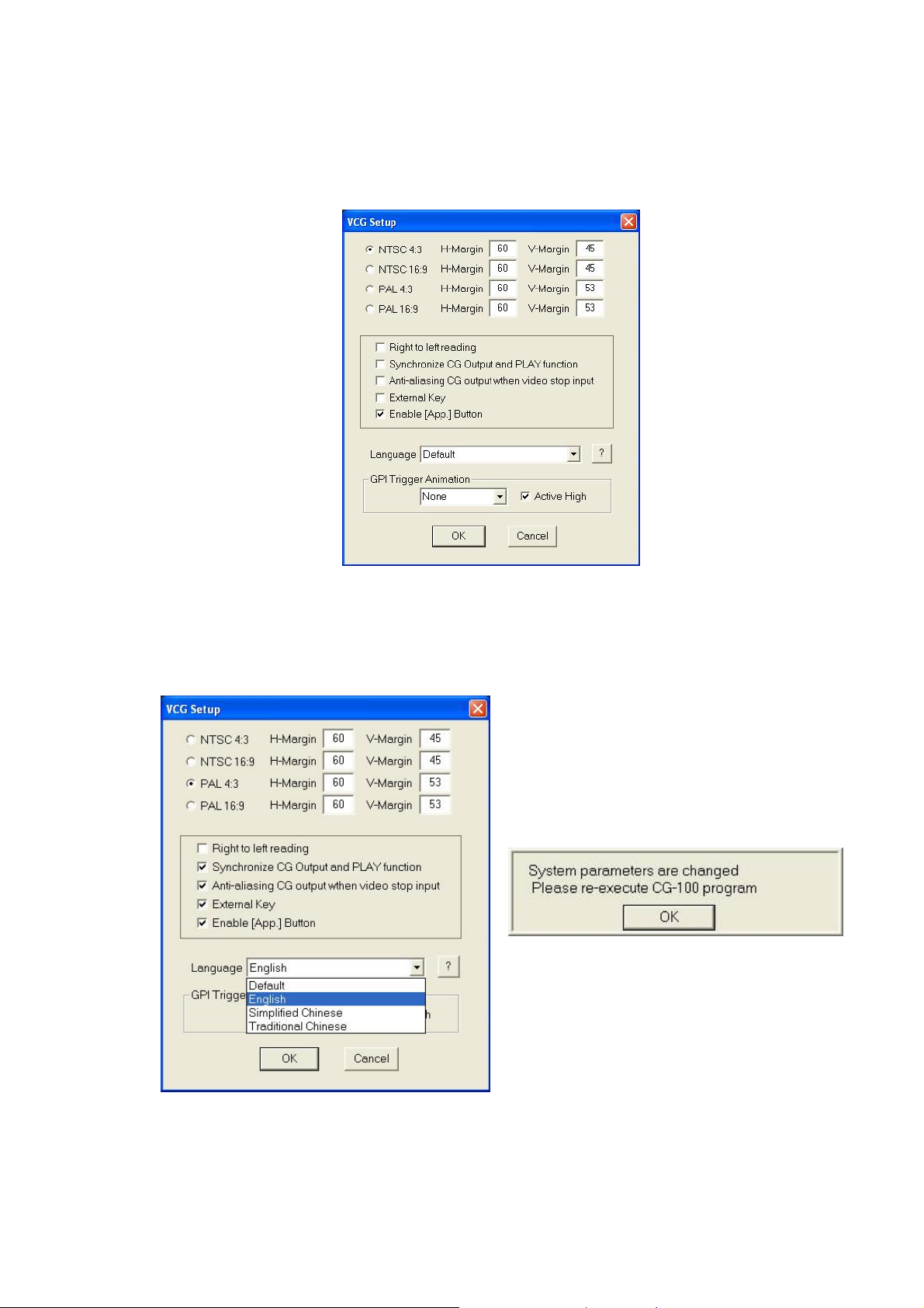
Language setting
Select the language s etting for your user interface. T he s oftware
needs to be restarted after selecting your chosen language.
20
Page 21
GPI Trigger
You can set a GPI to trigger the Animation objects like wipe, push,
fade etc in CG-100.
The following steps are used to set up a “GPI trigger”
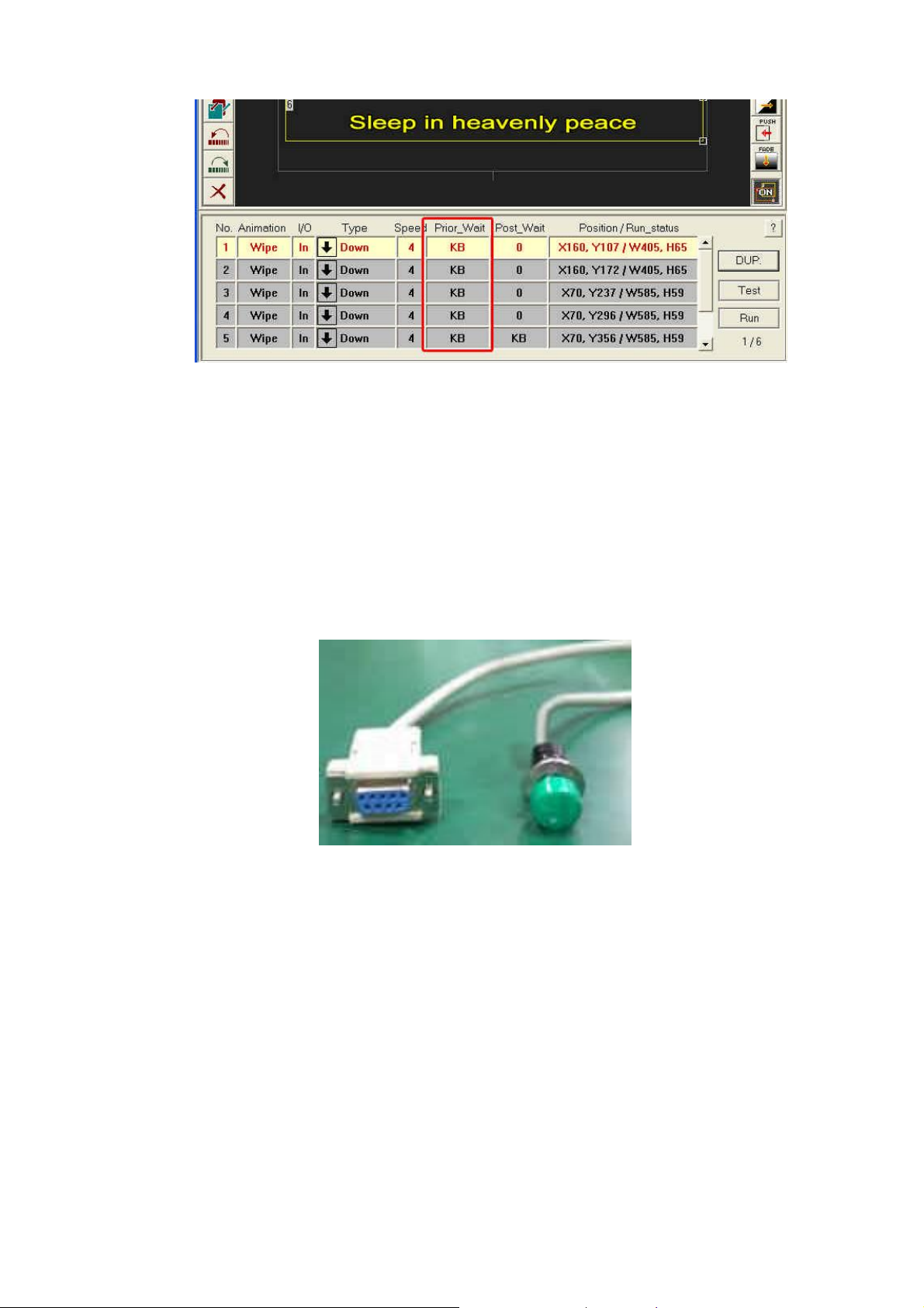
Step1 Set “Wait until keyboard” for the “Prior_Wait” and “Post_Wait”
of all animation objects.
Please note that between 2 animation objects, you do not have to set
“Wait until keybo ard” twice. For example, the user would then have to
send 2 GPI triggers to continue the motion. It is better have one
for KB (or GPI trigger) and set the other wait to “0 seconds” instead as shown
in the following image.
wait
21
Page 22
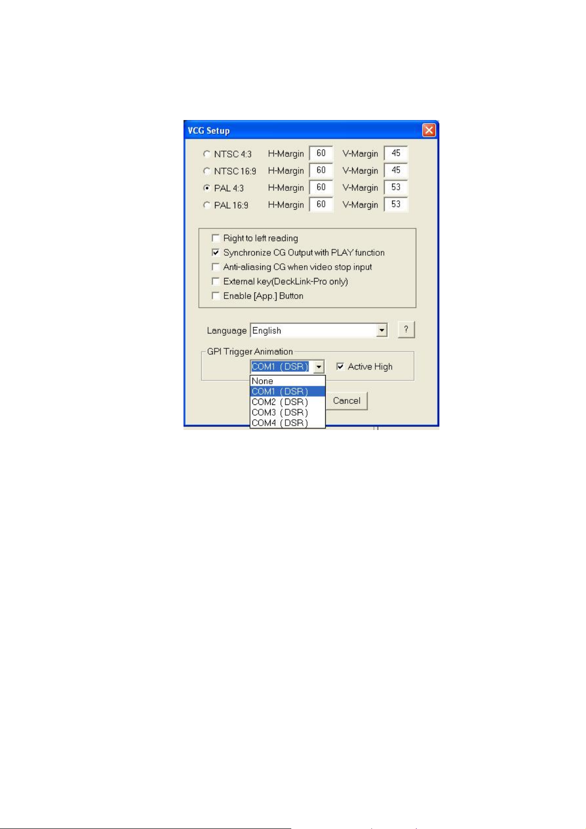
Step2. Go to [Setup] dialogue in [GPI Trigger], select from
COM1 to COM4 to choose one of the Serial Port DSR signal lines.
Connect the hardware GPI (General Purpose Interface) cable to the
selected COM port.
Step3. Tick Active High, this means when the DSR signal is
High Voltage, or GPI contact is made, the next animation will be
triggered. Off Active High, means when the DSR signal is Low
Voltage, the next animation will be triggered.
Step4
Method1
If your GPI is a switcher, the easiest way to connect the
GPI to the COM port is to connect the ON/OFF point (line) directly to
the 4th pin (DTR output) and the 6th pin ( DSR input) of a 9-pin Sub D
COM Port socket. In this case, please go to [Setup] and tick [Active
High]. When the GPI switch is ON, the positive Voltage from DTR
output goes to the DSR and it becomes High Voltage, so that it now
triggers the animation objects set as “Wait until keyboard” in CG-100.
The connection cable of the GPI can be up to 10 meters in length.
22
Page 23
Step4
Method2
If your GPI is a photo transistor, please note the
direction of electric current is from the 4th pin (DTR output) of COM
Port 9-pin Sub D socket to the 6th pin (DSR input). When the
ON/OFF points of the photo transistor are connected in an opposite
way, the GPI will not function properly.
Step4
Method3
If one of the GPI ON/OFF points has to be grounded,
then you have to place a 1k Ohm resistor bet ween the 4th pin (DTR
output) and the 6t h pin (DSR input) of the COM PORT 9-pin socket.
Meanwhile, the GPI ON/OFF points should be connected to the 6th
pin (DSR input) and the 5th pin (GND). In this case, the Active High in
[Setup] dialogue should be “OFF” for an Active Low setting.
Tools, Effects
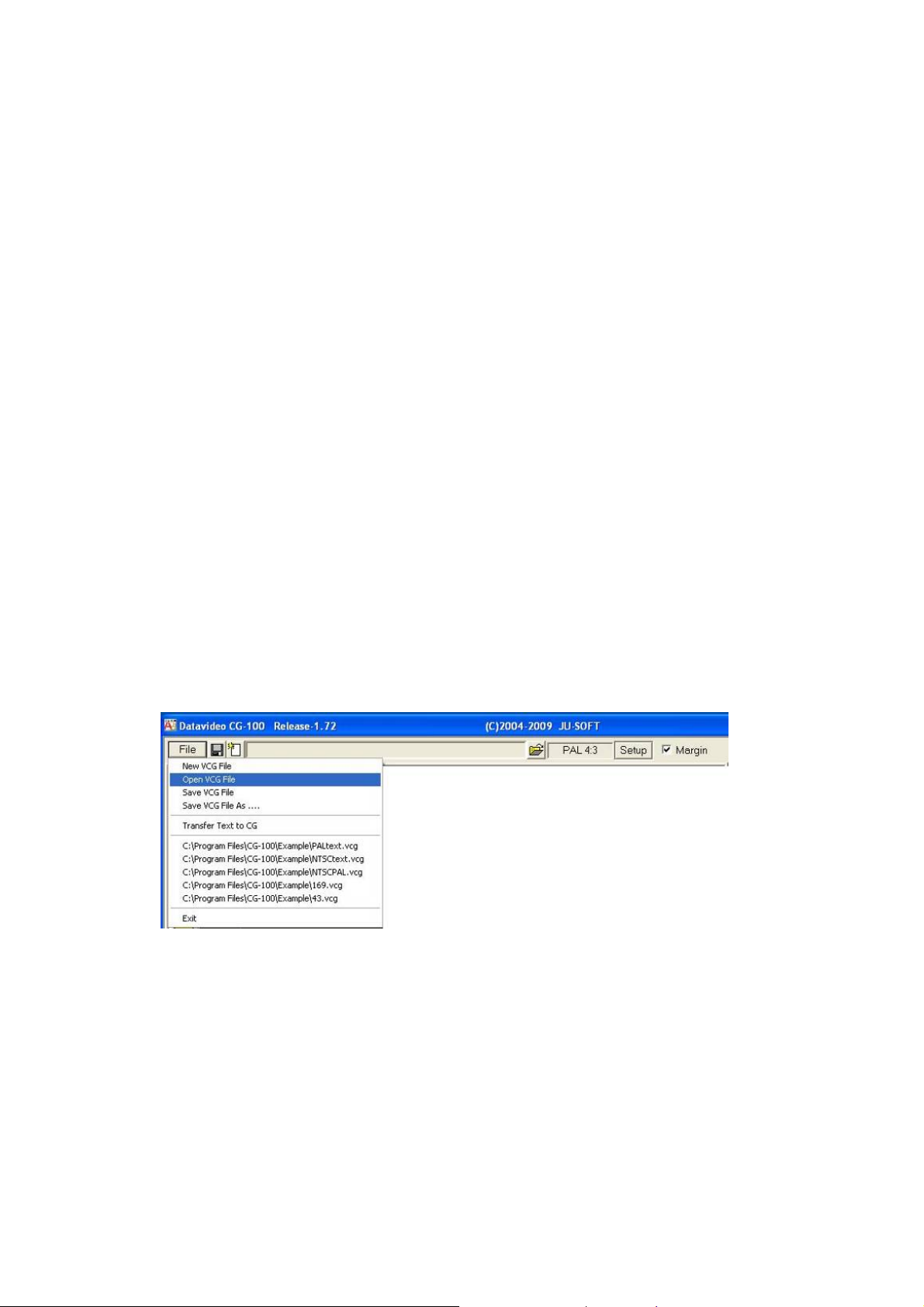
Files
The file format for a CG-100 project is *.vcg. Click the [File] button to
display the “File” drop down menu options.
Alternatively, you can also use buttons to save, or create a new *.vcg
file as well as opening existing *.vcg files or CG-100 projects.
23
Page 24
Pages
Each *.vcg file can include many “Pages” but only 4 are displayed in
the Page list as well as the current page in the Work Area. Each page
can contain
When a new *.vcg file is created, 4 blank pages will automatically
appear in the Page List. Click on one to select a page. You will see a
Red border highlighting the selected page. The highlighted page is
also the page that is currently in use or being changed in the Work
Area.
All the pages in a
side of the Work Area. If there are more than 4 pages in the *.vcg file
then a scroll bar to the right of the Page list can be used to view the
other pages.
The pages will be created in the sel ected standard and aspect ratio, either
4:3 or 16:9 and either NTSC or PAL. See the Set Up section for more
information.
The following image explains how the pages of a .vcg file will appear
in preview list on the right side of the Page Area.
3 kinds of objects: Text, Graphics and Animations.
*.vcg file will be shown in this Page list to the right
24
Page 25
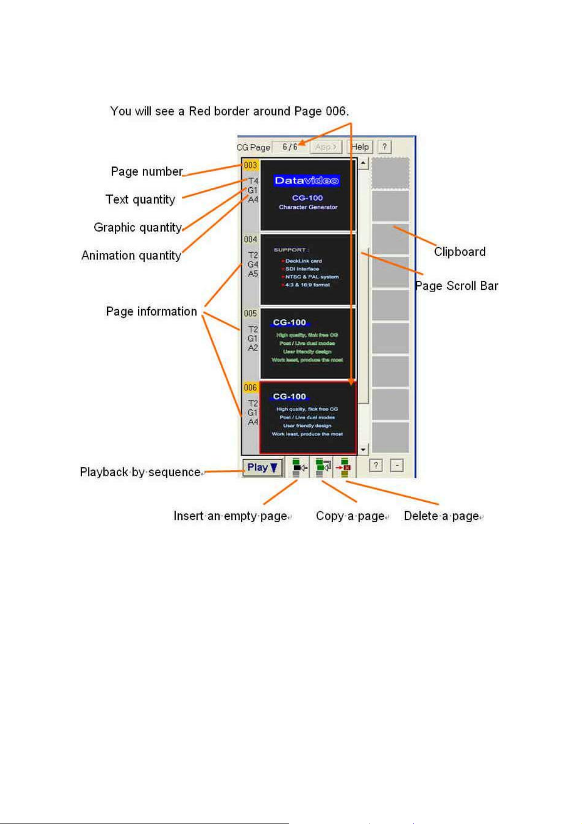
The current page is the sixth page and there are six pages in total.
You can edit a project by ins e rting, copying or delet in g pages with the
Page buttons at the bottom of the list. To change the running order of
the pages, just click on a page in the list and while holding down the
left mouse button drag the selected
Note: The selected page will not change posit ion in the list until you drag it
at least half a page above or below where it currently is.
page to its new position in the list.
25
Page 26
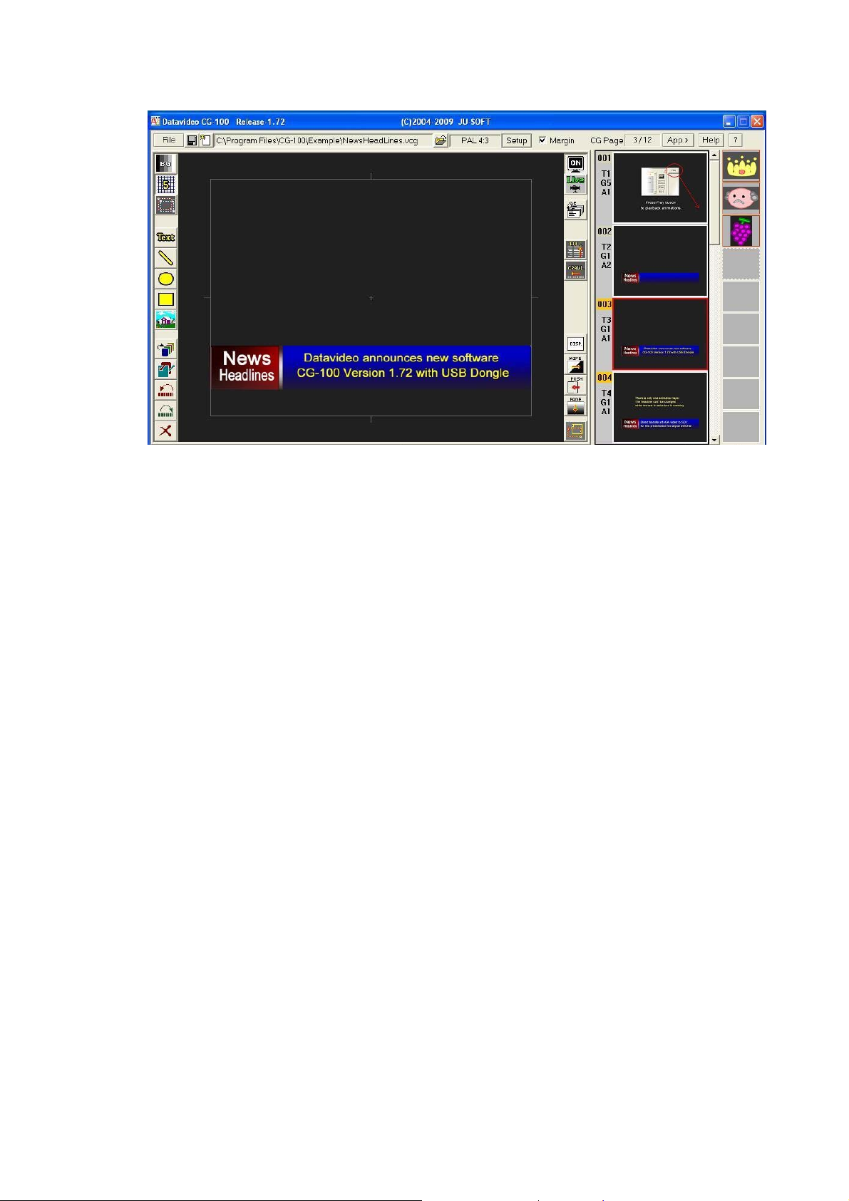
Objects
The Selected page is highlighted with a Red border in the Page List.
The same page is also shown in the larger Work Area.
To the left of the selected page in the Page List is the Page Numb er
(003), the number of Text Objects ( T3 ), the number of Graphic
Objects ( G1 ) and th e number of Animations ( A 1 ).
T3 means there are 3 Text objects on this page:
These are (1) the word ‘News’, (2) the word ‘Headlines’ and (3) the
sentence ‘Datavideo announces…’.
G1 means there is 1 Graphic object on this page:
The graphic object is the Red and Blue bar behind the text.
A1 means there is 1 Animation object on this page:
The animation object is the Wipe used to display the sentence.
The objects can be created, sized and alter e d. They can be moved
and layered on top of eac h other and to do this we use a varie ty of
Tools.
26
Page 27
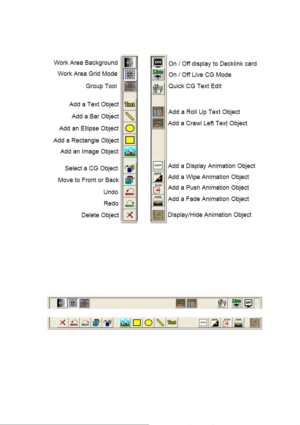
Layout Tools & Animation Tools
CG-100 offers the following Editing, Layout and Object tools:
In 4:3 aspect ratio set up, the Tool bars appear either side of the
Work Area.
In 16:9 aspect ratio set up, the same tools appear in horizontal bars
above and below the Work Area.
27
Page 28
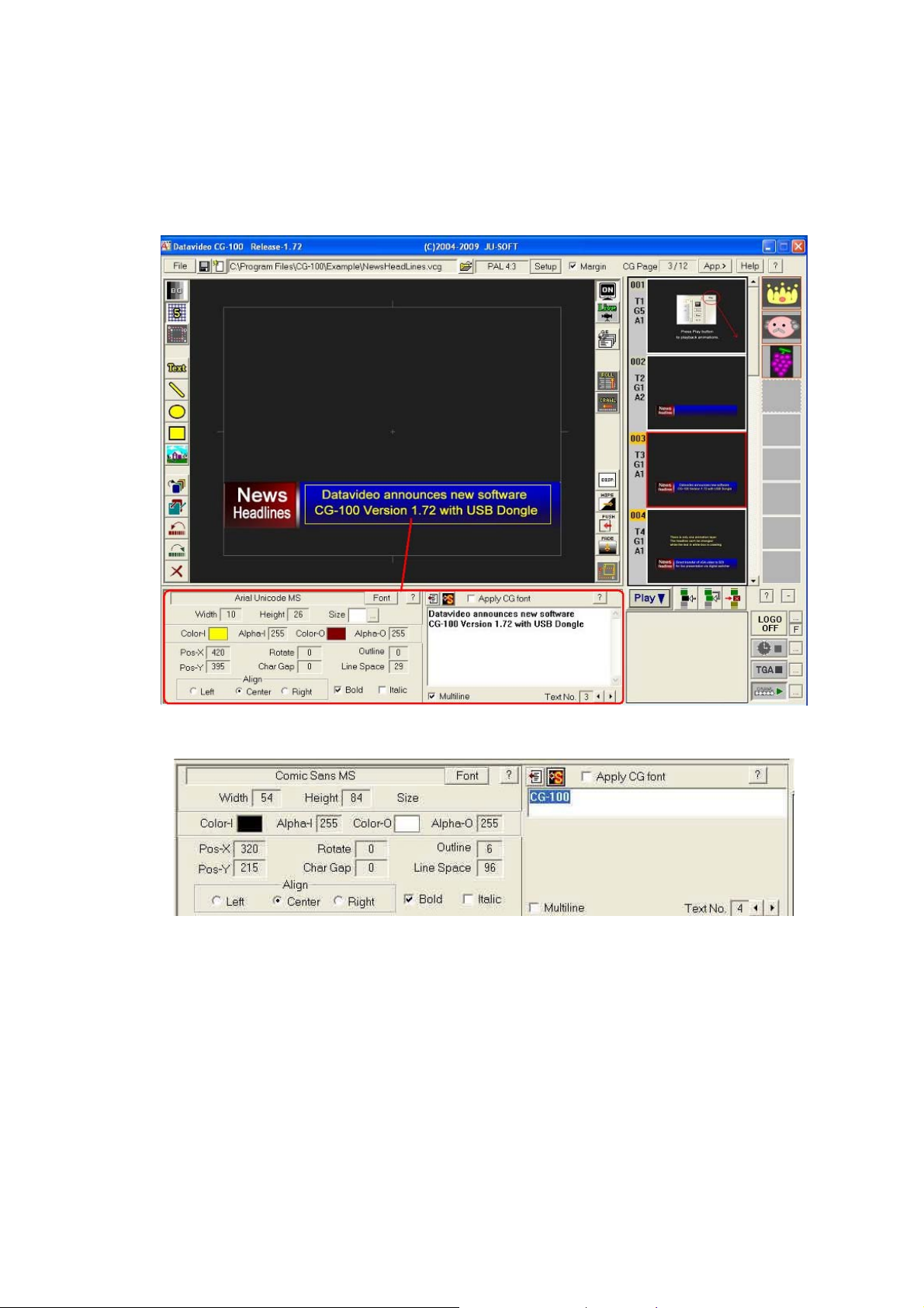
Parameter Panels
The CG-100 provides 5 editing tool-buttons for you to add Text, Bars,
Rectangles, Ellipses and Images. You can go to the Parameter Panel
to set the colours of text, the precise positions etc. Please see the
following examples:
Text Parameter Panel (1)
Text Parameter Panel (2) or Saved Styles Panel
28
Page 29
Text Parameter Panel (3) or Multi Line text
Graphic Parameter Panel
Image Parameter Panel
Animation List
The CG-100 provides 4 kinds of animations. You can click on the
buttons to insert a Display, Wipe, Push or Fade effect. After inserting
an animation effect, it can be edited on the Animation List Editing
Panel.
29
Page 30
Layout Editing
The CG-100 Layout is composed of 5 elements including text,
graphic bars, rectangles, ellipses and images. To edit the CG Layout,
you should do the following: Press one of the buttons on the tool bar
to insert a new object. Drag the object to the required position and if
necessary, resize it.
Set parameters on the Parameters Panels. If necessary, you can cut,
delete, and adjust the sequences among objects.
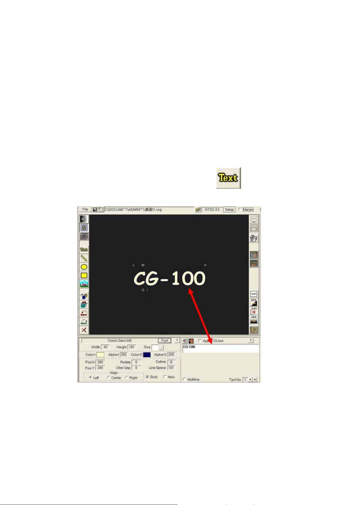
Text Editing
This is the way to insert a text objec t:
(1).Click Text button on the tool bar
A text object will be created in the working area.
Normally any text content is t he sa me as the previous text object.
A default of “Text Sample” will be shown for the first text object.
30
Page 31

Marks around a text object
The current editing text object will be surrounded by 4 marks:
How to Move a text object
Place the cursor on the text object, but do not put the cursor on any
of the 4 marks. Press and hold the left button. This will make the
cursor become a Drag Symbol, which means the text object is
selected and ready for editing. Hold the left button down and move
the mouse, the text object w ill follow the mouse.
Once the text is in the right place, release the left button. The meshed
surface allows you to see other objects through the selected one
while it is moving ov er t hem.
31
Page 32

Fine tune the position of a Text Object
It is hard to move just a pixel or two by using the object drag function.
In this case, you ca n press the keyboard arrow butt ons. Every arrow
press moves the text object one pixel in the chosen direction.
Note: While typing, the arrow buttons are for moving the cursor. If
you want to use the arrow buttons for moving the text object, you
have to use them immediately after dragging the object approximately
into position.
Resize a Text Object
Adjust the Gaps between letters (Kerning)
Press dual-squares and move the mouse horizontally – Right to
increase and Left to decrease.
32
Page 33

How to Rotate a Text Object
To rotate the object left click on the circle, hold the left button down
and move the mouse vertically.
33
Page 34

Change the content of Text Objects
You can type the cont ent of the text objects in the typing area under
the Working Area.
Change the text content here in the typing area
34
Page 35

A text object literally means a single-line. When you’ve finished typing,
press [enter] to update the text object. The below example shows
“CG-100” now amended to “CG String Sample”.
CG-100 will also automatically apply the alterations to a text object in
the Work Area too. Part of th e object may move outside the Wor k
Area if it becomes too big. Select the object by clicking on the cross
“+” and then drag to reposition it. Changing the font size may also
help.
To avoid this situation; just reme mber to set the alignment of the
object before amending the text object.
35
Page 36

There are three choices of alignment whic h affect the position of a
text object. These are align Left, Center and Right.
The text object will be moved horizontally as soon as you click a radio
button.
Multi-line Text Objects
You can create a multi - line text object, like a p aragraph of text.
Tick [Multi-line] to enable this function.
With Multi-line selected the typing area will be extended, so that you
can type a whole paragraph.
36
Page 37

Saving Text Styles
When you create a text object and want to save its style as a sample,
just click the Style button to open the [Text Styles] panel.
Step 1: Colours, fonts, outline and thickness can be stored in the
“Style Panel”. Click this to open the “Style Panel”.
Step 2: Click on a box to select a place for storing the current style.
37
Page 38

Step 3: Back to select the text line on the working area.
Step 4: Click this button to store the text style in the selected place.
You can also save all stored styles into a file that can be recalled for
different CG-100 project.
38
Page 39

How to apply a Style to a Text Object
First click to select the text object.
Double click on one of the styles in the panel and the style will be
applied to the selected text object.
Returning to the Text Parameters Setting
You can return to the parameters in the Text Parameter Pa n el.
Click [X] to close the Saved Styles window.
The Text Parameters Panel is shown again.
39
Page 40

The text parameters are:
Font True Type fonts, click the button to
select other fonts.
Width The width of letters. Press left button,
move the mouse horizo ntally.
Height The height of letters. Press left button,
move vertically.
Pos-X X field of the text object. Press left
button, move horizontally.
Pos-Y Y field of the text object. Press left
button, move vertically.
Color-I The fill colour. Click the colour to select
other colours.
Alpha-I The opacity of the fill. Press left button,
move horizontally.
Rotate Rotate the text object. Press left
button, move horizontally.
Char
Gap
Gaps between letters. Press left
button, move horizontally.
Color-O The colour of the outline. Click the
colour to select other colours.
Alpha-O The opacity of the outline. Press left
button, move horizontally.
Outline The border of the text object. Press left
button, move horizontally.
Line
space
Align
left /Top
Align
Center
Only for Multi-line text object s. Press
left button, move horizontally.
Set the Axis of the text object (the
cross
left to right,
mark) to the left/top. Words add from
top to the bottom.
Set the Axis of the text object (the
cross mark) in the center. Words go
from left to right, top to bottom.
Align
Right
/Bottom
Set the Axis of the text object (the
cross mark) in the center. Words go
from left to right, top to bottom.
Bold Tick to make the fonts bold-faced.
Italic Tick to make the fonts Italic.
40
Page 41

Using the Mouse to set parameters
You can set a text object’s parameters using the mouse too.
Click on a Tick box to select bold-fac ed fonts or click a radio button to change
text alignment.
Other parameters can be set by holding down the left mouse button and then
moving the mouse horizontally to increase or decrease its value.
For example, if you want to set the transparency of a text object:
Select a text object.
Click on the value box of the “Alpha-I” parameter.
Press and hold the left mouse button.
The mouse pointer will change shape to
Whilst still holding the left hand mouse button move the mouse
horizontally left and right to change the level of transparency.
You will see opacity of the text object changes immediately within the Work
Area.
Vertical Text Objects (Asian fonts)
For some Asian languages, sometimes text goes vertically. If you want a
vertical text object, follow the steps below.
Open the Font dialogue box.
Select a font with a name that starts with the @ symbol.
Set the parameter of [Rotation] to 270°.
Note: Double click on the value box of the [Rotate] item and the program will
Automatically reset to the default angle for that font.
For font names that start with the @ symbol, the default angle is 270°.
For all other fonts the default angle is 0°.
Default width of a Letter or Character
The default width of a letter for a Windows PC is half of its default height.
If you want to return a font to its default setting, please double click the value
boxes of the [Width] or [Height] parameters.
Double click [Width] item, the width will be 1/2 of its height.
Double click [Height] item, the height will be 2 times its width.
41
Page 42

Importing Text from a Text File
If you need to use a large amount of text or text in foreign languages,
you can import the text from a file. The CG-100 allows you to import
text from a *.txt file.
Step 1: Create a new text object with the text tool.
Step 2:
Click this button to import text from a file.
Step 3: Open a text file.
42
Page 43

Step 4: Highlight the text to import and click the button
Inserting a Graphic Bar or a Line
Click this button to insert a bar or a line.
There are 2 square marks on both ends of a graphic bar. You can
drag on either square to alter the bar’s length and position
.
43
Page 44

The parameters of the grap h ic ba r/ line can be set on the following
panel.
Bar
Width
The width of the graphic bar/ line,
press left button and move the
mouse horizontally
Outline
The thickness of its outline, press
left button and move the mouse
horizontally
Inner
Colour
The fill colour, click for further
settings
Outline
Colour
The outline colour, go to a dialog for
further setting
Inner
Alpha
The opacity of the fill, press left
button and move the mouse
horizontally
Outline
Alpha
The opacity of the outline, press left
button and move the mouse
horizontally
Examples of Graphic Bars and Lines:
44
Page 45

Inserting a Rectangle or an Ellipse
Click this button to import a rectangle
To move this rectan gl e, click the inner part then mo ve it.
To resize the rectangle, click the square on the bottom right and
move it around.
Click this button to import an ellipse.
To move this ellipse, click the inner part then move it.
To resize this ellipse, click th e s quare on the bottom right then move
it around.
45
Page 46

Parameters Panel for Rectangles and Ellipses
Outline The thickness of its outline, press left button
and move the mouse horizontally
Inner Colour The fill colour, click for colour palette
Outline Colour The outline colour, click for colour palette
Inner Alpha The opacity of the fill, press left button
and move the mou se ho r i zon tally
Outline Alpha The opacity of the outline, press left button
and move the mouse ho r izontally
Many Kinds of Ellipses and Rectangles:
46
Page 47

Inserting an Image
Step1: Click this button to insert an image object. This may
be a blank square to begin w ith.
Step2: Click “File” to select an image file. The image will be shown
on the working area.
47
Page 48

Step3: Click the centre of the image to
move the image.
Step4: Drag the square in the
bottom right to resize the image.
48
Page 49

Step5: Use the Image Parameter Panel as follows:
Image File Shows the file path of the image
Position Shows the X and Y pixel position of the image
Size Shows the width and Height size of the image in
Pixels
Alpha Shows the opacity or transparency of the image
Colour Key This tick box enables a colour to be keyed out
Key Colour Click and choose a colour for keying
The chosen colour will become totally transparent
The transparency of an image
When you set the transparency of an image, the setting is applied to
the whole image. The levels of transparency are from 0 to 255. Zero
0 is fully transparent while 255 is fully visible. If the image format is
Targa 32 bit, then the transparency set here will multiply by the files
original alpha. (Note: Some third party applications such as Adobe
Photoshop allow users to create Targa 32bit images.)
A Targa Alpha=255 Alpha=85
49
Page 50

Select an image colour to be transparent
Step1: Insert the image file and Tick th e Colour Key box.
Step2:
To turn the mouse pointer into a colour selection dropper
press the […] properties button.
Step3: Place the dropper over the colour that will be transparent.
Click left button to select the colour. You can adjust the number
to remove the background and achieve the best effect.
Step4:
The selected blue colour in the above example image
becomes transparent.
50
Page 51

Extra Editing Tools
The CG-100 provides extra editing tools that make CG editing easier.
Background button
The default background of the Work Area on the CG-100 is Black.
However, if a title is very dark o r the outline has to be black, it cannot
be seen clearly with the black background. So the [BG] button allows
you to change the background colour. Wh en you click the button, the
background will be changed from
Gray and to White. It then returns to Black as it goes around as a loop.
Please see the following background colour examples:
Black, to dark Gray, to Gray, to light
Grid Mode button
The snap to grid makes aligning objects much easier. When you click
the Grid Mode button , it goes around in a loop from X, to 5, to 10. The
[X] means the grid function is disabled. The [5] means the snap to
squares are 5x5 pixels. The [10] means the snap to squares are
10x10 pixels.
Group button
Click the [group] button to display the group menu with the following
options.
51
Page 52

Top/ Bottom
The objects on the CG-100 working area ar e p laced in the order they
were created. The first insertion is on the bottom and the last one is
on the top. Of course it doesn’t matter if no items are overlapping.
However, if more than two objects overlap, the Top / Bottom button
enables you to put the layers in the right order.
Click to select an object on the working area.
Then click the [Top / Bottom] button.
Every click moves:
The front object to the back
The lower objects all move one layer forward.
Delete
Click to delete the selected object.
Undo / Redo
Cancels or retrieves the last applied effect or command; i.e.
reverts to previous attributes.
52
Page 53

Group Move/Zoom
Click [Group Move/Zoom] button, There will be 2 boxes, the blue one
and the red one. The red box, the source box, is to select the sour ce
object/s - usually more than one object. The blue box, the destination
box, is to place and resize the result. If the red box is as big as the
blue box, then the group of objects is just moved to another place. If
the blue box is not equal to the red one, that means the group of
objects will be moved and resized.
To perform this function, you need to place the cursor on the squares
on the source box or on the destination box as below.
The following is a group of CG objects which include a water lily
image, a green bar and a text object, “VCG Sample”.
53
Page 54

If you want to enlarge the whole group, the st eps are as follows:
a.) Place the cursor on the top left side. Drag the red box to
encompass the objects.
b.) Drag the red FRAME to the top left side of the group of objects.
c,) Place the cursor to the bottom right of the red box. Then drag to
resize the box
54
Page 55

f.) Then place the cursor to the top left side of the blue box.
g.) Drag to move this blue box to the destination.
h.) Put the cursor on the bottom right. Drag to resize the blue box.
i.) Drag to resize the blue box. The size of this blue box represents
how big the whole group will be.
55
Page 56

j.) When all the adjustments are done, click the annulus to finish
and display the result.
The original group
k.) You will see the whole group has been enlarged to the size of
the blue box.
The result after
executing [Group
Move/Zoom]
If you want to undo this function, just click the [Group Move /
Zoom] button again to revert to the original settings.
56
Page 57

Group Copy/Cut/Delete
After clicking the Group butt o n, select one of the options: [Group
Copy], [Group Cut] and [Group Delete]. These functions all create a
blue and white outlined box on the working area. Place and re-size
the box to surround the t arg et ob je cts. Then you can copy, cut or
delete the objects inside the box
Unlike when cropping an image, the CG-100 will copy, cut or delete
the entire object instead of a portion of it. So, when the blue and
white box only surrounds a part of an object, the CG-100 will verify
whether the center of the object is inside the box. If so, the object is
selected. If not, it is not selected.
Once the blue and white box is surrounding the target objects, click
the annulus to start copy, cut or delete. Below is the result after doing
the cut or delete.
The copy function allows you to copy the group of objects to the CG’s
clipboard.
There are 10 spaces to store them. If yo u want to retrieve this group
of objects, click the clipboard to paste the group in the original
position on a page.
57
Page 58

Animation Editing
The CG-100 offers various animations such as Display, Wipe, Push,
and Fade; also Roll and Crawl to scroll text across the screen or up
the screen.
Setting up an Animation Box
Display, Wipe, Push and Fade, each of the four animations has a box
and a set of parameters. You should re gard the working area
dimensions. Select any part of it to do th e animations
Here is an example with 3 single-box animations:
The 1st animation box “VCG” is selected and set as Display-In,
pressing any key will activate this animation.
The 2nd animation box “Sample” is selected and set as Wipe-In-
Right.
The 3rd animation box “VCG Sample” is selected and set as Fade
Out, pressing any key will activate this
animation.
as two
58
Page 59

As long as the animation bo x is pu t on the working area, the detail of
the animation will be s hown on the animation list which is beneath the
working area.
The parameters of the animation list are:
No. The number of the animation.
Animation Select an animation like Display, Wipe, Push or Fade.
Click the right button her e to chan g e to a d if ferent
animation.
I/O In/Out, shows whether the animation is affecting the
way the object appears or disappears.
IE: A Fade In and a Fade Out
Click the right mouse button here to select in or out.
Type The direction of an animation. Click the right mouse
Button here to select different movements.
Speed Determines how fast an animation moves. Click the
right mouse button here to select a different speed.
The higher values increase the speed.
Prior Wait Determines how the animation will be triggered.
Click the right mous e bu tt on here to select differe nt
ways. For example, this may be a time delay or a key
press.
Post Wait Determines how you want to proceed to the next
animation. Click the right button here to select
different ways. For example, this may be a time delay
or a key press.
Position The x, y coordinates of an animation box. Click the
right mouse button here to position the animation box.
You can only use one animation at a time from the animation list. The
current one on the list is highlighted in yellow with red words. The
corresponding an im ation box is also highlighted in red and yellow.
59
Page 60

Editing Animation Boxes
Step 1.
Use this button to make a text object.
Step 2.
Create an animation type by using these butt ons.
Step 3. Click this button to show all animation boxes.
Step 4. Surround only the target object(s) with an animation box.
60
Page 61

Step 5. All the animations will be listed as below. Change the
attributes by clicking the
RIGHT MOUSE BUTTON to launch the
dialogue for further settings.
Step 8. Play all animations
page by page
Duplicate the selected
Animation box.
Step 6. Test a selected
Animation on this page.
Step 7.
Run all Animations
on this page.
61
Page 62

To add a [Display] Animation
Display is a basic animation.
Click [Display] button on the toolbar to create a red and yellow
outlined animation box on the working area.
As you create the display animation, it will appear as a row in the
Animations list below the working area. Now drag the animation box
to surround the CG-100 object(s) that it will affect.
62
Page 63

Place the animation box around an object such as a text object.
Then set the parameters in the animations list.
You can select [Display] [In] or [Out]. [In] means to show the area,
[Out] means to hide the area .
The default setting of display is [Display-In]. Put the cursor on the [In]
field and click right button to select [Out] from the pop-up menu as
shown below. Select [In] or [Out] to finish the setting
[Display] requires no settings for [Type] or [Speed] but you will have
to set the [Prior Wait] and [Post Wait] settings. If you tick the “W ait to
hit key” on the [Prior Wait] the animation will not start until you hit the
Ctrl key on the keyboard. To do this, place the cursor on this field and
click the right mouse button to open the pop-up dialog for setting.
In this field [Prior Wait], you can also select a wait time in seconds
before the animation starts
In this example, we have chosen [Wait Hit Keyboard].
[Post Wait] defines how long to wait after doing an animation. To fix
the [Post Wait] setting, place the cursor on this field and click the right
63
Page 64

mouse button to open a pop-up dialog as below.
You can either type the [Post Wait] value directly or click the
Arrow buttons to set the seconds. Click [OK] to f in ish the setting.
Finally, click the right mouse button on the field of [Position] the
cursor will switch to the top left side of the animation box in the
working area so that you can drag to resize the animation box.
64
Page 65

To add a [Wipe] animation
Click [Wipe] on the tool bar to create a new Wipe animation box.
If there is an existing animation, you can also click the [Duplicate]
button and then change its parameters to become a [W ip e]. Place the
cursor on this field and click the right mouse button to open a pop-up
menu.
Select [Wipe] animation
You will need to set the [Type] and [Speed] for the wipe animation.
Place the cursor on the field of “Type”, click the right mouse button
to open the pop-up dialogue.
In the [Wipe Type] dialog box, select the wipe you require. In this
example we selected a right direction wipe.
In the [Speed] field, right click the mouse to open the pop-up menu.
65
Page 66

Choose the required speed. Then the setting is finished.
Calculate Animation Time
You can estimate the time an animation will take as follows. If the
animation box is 120 pixels wide and the speed of WIPE is 4 pixels
per frame, then it will take 30 frames to run this animation. In NTSC
mode, it takes 1.0 second, while in PAL mode this will take about
1.17 seconds.
Prior Wait and Post Wait Time
If you have a set of wipe animations and do not set a “Prior Wait” time
then the next animation will appea r immediately after the previous
wipe “Post Wait” time. If you set both the Prior Wait and Post Wait
values then there will be a wait delay of both values added together.
Trigger Animation with Keyboard (KB)
A flexible way to trigger the entrance and exit of a “Wipe” or other
animation is to right mouse click on Prior Wait or Post Wait value and
then Tick [Wait Hit Keyboard] in the pop up option. This lets the
operator decide when to start or end the animation with the Ctrl key.
66
Page 67

To add a [Push] animation
You can click [Push] on the tool bar to create a new PUSH animation
box.
If there is an existing animation, you can click [Duplicate] then change
the new animation line settings so it becomes a [PUSH].
Unlike [Display] and [Wipe], [Push] cannot be used to preserve the
screen on the last page even if you set the CG page attributes to
reserve last screen or page.
See the next section to understand the difference between the effect
of a [WIPE] and a [PUSH] with reserve last screen.
67
Page 68

[WIPE] with Reserve Last screen
This first example shows the first page contains a Display animation,
then the second page contains a wipe animation and this page also
reserves last screen. When the two pages play back, the blue box
acting as a background for white text will not be cleared.
68
Page 69

[PUSH] with Reserve Last Screen
This second example also sets first page to have a [Display]
animation, then the second page contains a push animation and this
page also reserves last screen. But this time, when the two pag es
play part of the blue box will be cleared in order to push the selected
white text area.
Note part of the blue background is missing as the text Push is done.
69
Page 70

To add a [Fade] animation
Adding a [Fade] animation is just the same as adding other
animations already covered earlier in this manual.
To insert a [FADE] animation, click the [Fade] button on the toolbar or
first duplicate the previous animation and then modify it to be a
[FADE].
Delete an existing animation line
To delete an existing animation, simply select the animation box and
press the delete key on your keyboard or right click the mouse and
select delete from the popup menu.
Change the order of animations
To change the sequence of animations, select one of the animations
on the list and simply drag it to the desired position in the sequence.
70
Page 71

Duplicate an Animation Line
If there is an existing animation, you can click the [Duplicate] button
and then change the parameters of the new line to suit your
requirement.
Place the cursor on the animation field and click the right mouse
button to open a pop-up menu.
Select the required type for the newly created animation line.
Roll and Crawl
To Roll a List
The CG-100 provides the Roll function to roll a text list.
Step1: Click this button to create a Roll page.
Please be aware ther e c an be only one Roll or Crawl obj e ct in a pag e
Limitation s of a RO LL object
There can be only one Roll or Crawl object in a page.
A Roll object can be no longer than 10 pages in height.
71
Page 72

Step2: To edit a Roll object, click the object in the working area.
Step3: Define the Roll object in the roll object panel.
Step4: To set a dual string roll object like the sample on the panel,
use // to separate 2 strings of text on every line. The part on the left of
// is one string and the part on the right is another string. Set different
colour, fonts for the strings using [style-1] and [style-2] button.
72
Page 73

Further settings of the Roll object panel
Un-check [Dual Styles] to create a single string roll object or tick this
box to create a dual string roll object.
Click [style-1] or [style-2] but ton to edit the parameter of the string
To return to the Roll object panel, click this button.
To import text from a txt file, click [Note Pad] to find and open the file
then copy and paste the required text into the Roll object text panel.
Click the [update] button when you import text from files
Once the Roll object has been altered, click to run the Roll
object.
73
Page 74

To adjust the size of a Roll Object
The size of a Roll Object is adjustable.
Step1:
Step2: Move the Roll obj ect to the required position.
Use the cursor to resize the Roll object.
74
Page 75

Step3: press [Style-1] to amend the position and other attributes of
this part of the text string.
Step4: Change the string position by adjusting the Pos X value.
Style-1
75
Page 76

Step5: Now do the same with the other part of the string by adjusting
the Pos X value for Style 2.
Style-2
Step6: You can now place another tex t object on the screen and
create an animation box for the new text object. Then arrange the
playback sequence so all elements play correctly.
76
Page 77

To adjust the size of a Crawl Object
Step1: click this button to create a crawl object
Please be aware there c a n b e onl y one Roll or Crawl object in a
page.
Limitation of a Crawl object:
There can only be one Roll or Crawl object in a page.
A Crawl object cannot be longer than 10 pages in width.
Further settings of the crawl parameters can be adjusted in the same
way as a Roll Object see
changed.
page 74 for examples of what can be
77
Page 78

Live CG Editing
You can add CGs easily at any time during a post production work
flow. It is also possible to use CG-100 in live production work flow
and still have enough flexibility to provide good overlays with a small
amount of time. Here’s how…
Pressing this button
…. allows you to multi task so that whilst you are displaying one CG
page on TV you can also be amending or preparing another CG page.
78
Page 79

Make sure the current page is being output Live.
You are now ready to edit off line.
Move the mouse pointer to the
information area just to the left of the
CG Pages list.
You will see the mouse pointer change
colour from green to red.
Click the left mouse button when the
pointer is red and the background
colour of the information area will now
become pink.
The selected page sh ou ld no w be re ad y
for off line editing. All th e ob je cts on the
selected page for off line editing will
also be shown in the work area to the
left of the CG Page list.
Live Status Panel
79
Page 80

Whenever you want to quit the off line Live Editing mode, remember
to click the appropriate selection of TV-On or TV-Off.
If you don’t pay attention then the page currently being edited may be
accidentally output before it is ready to be shown.
If the curren t page being edited is not ready fo r output, select TV-OFF
before quitting the off line Live Ed iting mode.
80
Page 81

Quick Edit function
Think about this, in a talk show, the video will switch from the host to
several different guests. The layout of the pages are set and there
are just some names that need to be changed. If you need to edit
something similar in a ve ry sh ort time, this function is really useful.
Click this button to open “Quick CG Text Editor ”
This allows navigation from page to page to modify text or duplicate
similar pages in a very efficient way.
Modify the Text
Step1: Select the page that you want to alter and click the Quick
Edit button. The Quick Edit panel will be shown as below.
We can see on page 15 there are 4 Text, 0 Graphics and 0 Animation
objects.
In the above panel image, we see there is a 3 line text object. For this
example, there are 3 text lines: CG-100, Text Sample and Datavideo.
But all of them are listed in the Edit text box. It doesn’t matter if there
are single lines, multiple-lines, or a mixture of them.
Step2: Place the cursor on the line to be altered. Change the words
directly.
Step3: Press the [Enter] key to upda te the CG.
Step4: If there are other pages to be modified, Press [PgUp] or
[PgDn] keys on the keyboard to select the previous or next page.
You can also mouse click the Up/Down buttons next to the page
number to look for the desired page. Once you have found a page
that needs to be altered, again repeat steps 2 and 3 above.
81
Page 82

Page List
The Page List is used to view and select different pages in a CG-100
project.
At the top of this area the current
page number and total number
of pages
are displayed.
At the side of each page
displayed in the list is the
number
It also displays the number of
Text objects
Graphic objects
Animation objects in that page
To
select a page from the page
list place the mouse pointer over
the required page and left mouse
click. A
appear around that page. At the
same time the selected page will
also appear in the main work
area.
At the bottom of the Page List are
4 buttons. These are used to
Play the pages in sequence, or
Insert a new blank page, or
Duplicate an existi ng pa ge , or
Delete a page.
in the CG-100 project
page
and
red border will then
82
Page 83

The effect of Reserve Last Screen
Step1:
clone it.
Step2: Replace the original graphic object on the second page. Keep
the new graphic object the same size and at the same position.
Step3: Set different animations for page 1 and 2. In this example,
page 1 is “Push” and Pa ge 2 is “W ipe ” .
Select a page. Click the duplicate page button to
83
Page 84

Step4: When selecting page 002 with the mouse on the page list.
Click the Right button to open a Pop-up me nu. Choose Reserve last
screen here.
Reserve last screen
We can see the effect of page 002 is as below
Step5: When selecting page 002 a second time, again with the
mouse on the page list. Click the Right button to open a Pop-up menu
and this time choose Clean last screen instead.
84
Page 85

Clean last screen
Select “Clean Last Screen”, the effect on page 002 will be like below.
85
Page 86

Clipboard
Group copy to Clipboard
Step1: To copy a group of objects to the clipboard click the Group
Button.
Step2: From the popup menu select Group Copy.
Step3:
square handles, in the top left and bottom right corners, of this blue
box to position and re-size the selection box around the object(s) to
be copied.
Step4:
selection box to add the selected object(s) to the clipboard.
A blue selecti on box will appear on the work area. Use the
Click the annulus in the top right hand corner of the blue
86
Page 87

Lock/Unlock the Clipboards
Paste from the Clipboard
Select a box in the clipboard
and click right mouse button.
Choose “Lock” from the popup
menu. The object(s) in the
locked box will be saved.
To unlock the clipboard, select
the box and click right button,
choose “Unlock”.
Double click an icon from
the clipboard, a blue box will
be shown in the working
area. Click the annulus on
the right top of th e blue box
to paste the object(s).
87
Page 88

LOGO
The Logo function is the simple and easy way to add a logo. You can
also use the Logo Generator Application to utilize CG-100 as
professional Logo Generator. (Please see the Application, Logo
for more information.)
To add a simple Logo, please follow the steps as below to create
your own logo.
The Logo Editing Page is different f rom ot her pages. You can identify
it by its background colour which is blue instead of black.
You will not see this LOGO page in the Page List.
To edit a Logo follows these steps:
Step1: To edit the logo, please click the button as shown below.
Step2: Edit the Logo. You can use the objects to combine a logo or
import an image file. Move the logo to the desired position.
a
Generator
88
Page 89

Step3: Create a display animation object by clicking
And place the display box to surround the logo.
Step4: To leave this logo page you can click mouse right button and
confirm the message box , or just click on a page in the Page List.
Step5: To output the new Logo to the TV screen, please click the
Logo On/Off button. Remember that the Logo shows only in the
“Play” / “Run” / Live modes.
Step6: You can also click the B / F button to show Logo in the
Foreground or in the Background.
Background Foreground
89
Page 90

Clock & Stop Watch
Clock
To insert a clock object on the screen, first click the following button
1. Setting
Click the circled button to launch the Clock
properties dialogue box.
1.) Tick the Clock Date box.
2.) Select the Clock and Date format.
2. CG Position
Click the Edit style button then CG Position button to adjust the clock
layout. The text size, colour and position c an th en be ad justed also.
90
Page 91

3. Start
4. Stop
Please note that the Clock won’t show on the PC’s screen. It is only
shown on the TV screen.
Timer / Stop Watch
1. Setting
Click the circled button to launch the Clock
properties dialogue box.
1.) Tick Stop Watch.
2.) Select the time format.
91
Page 92

2. Edit Style CG Position
3. Pause
4. Start
5. Stop
Please note that the Timer will not show on the PC’s screen. It is only
shown on the TV screen.
92
Page 93

TARGA Sequences
You can import 3D animations or motion pictures as a sequence of
targa files. Click the following button to prepare a targa sequence.
1. Setting
2. Select Targa Sequence
93
Page 94

3. CG Position
Click this button and then mouse drag the item to adjust the size and
the position of the Targa sequence on the screen.
4. Background/ Foreground
Tick the check box to set TGA background or foreground display.
5. Memory Requirement
Check if the computer has enough memory for the TGA sequence.
6. Play Targa Sequence
7. Clear Targa Sequence
Please note that the TARGA won’t show on the PC’s screen. It is only
shown on the TV screen.
94
Page 95

Transfer Text to CG function
The transfer text to CG function in CG-100 generates subtitles from
text files.
Before doing text to CG tr an sfer, a sample page must be pr ep ar e d
like the above picture. Three text string objects ar e placed on the
lower third of the working area. These will represent the subt itles so
there will be three lines of subtitle text per CG page. You can set as
many text samples as you like. The pos itions, colours, and fonts of
these subtitles will be set based on the sample page.
The text objects on this sample page should be single-lined only as
using the multi-line version will cause incorrect display later on.
Go to [File] dropdown menu [Transfer Text to CG] to open the
following dialogue box.
95
Page 96

Click the [Text] button to select a text file and show the content.
The following is the content after a text file is opened.
Please note these principles while you prepare the text for subtitle.
Every line of text substitutes a string object. Every string object for
this sample page has its own sequence number beside it. In this
example, there are 3 string objects on the sample page, which means
the maximum number of lines of CG will be 3 lines in a page and
follow the sample page sequence.
The subtitles in a page can be less than 3 lines. To do this, enter a
blank line separating two groups of text. Text under the blank line will
be on the next page.
Tick [Reverse ord e r] to place the subtitle conversely. Reverse order
will place subtitles from bottom to the top. This way there will be less
text over the screen.
Tick [Delete sample page] to delete the first sample pa ge.
Click [Transfer] button to start transferring from text to CG.
96
Page 97

You can see the result as below
:
Number Tags for text objects
In order to help you verify the sequence of text samples in the sample
page, there is a number tag for every string. The first string will be
marked in a red tag as number 1, the second will be 2 and so on.
Try using the wheel on the mouse to s croll through CG pages. In this
version you can scroll page lists by rolling the mouse wheel. In Live
CG mode it can be an easy way to display subtitles.
97
Page 98

Single Text Crawl Button
This button in the CG-100 layout screen allows a single horizontal or
vertical text crawl to be set up quickly and easily.
The <Crawl Left and ^Crawl Up opt i ons are fairly straight forward and
can be modified for size, colour, font, position and kerning in the
same way as other text objects except setting up a display box is not
required.
However, the >Crawl Right option is designed for Right to left reading
fonts like Arabic and Hebrew. If you wish to use this feature please
first set up CG-100 for Right to left reading. See
page 17 also.
98
Page 99

App Button
Logo Generator
Logo Generator is a special plug-in application of CG-100.
To enable this application, please
go to SETUP and tic k “Enable [ App]
button”. If you do not need this plug
in, remove the tick so that the App
Button box is empty.
Please note that when you click into
the logo generator, the normal
CG100 function will be hidden until
next time the program is restarted.
Even when you click > back to the
CG-100 layout editing window, it
looks like the ordinary CG-100 window but it is not the same function.
Features of the Logo Generator
5 Independent layers of titles and graphics.
1 bo tt om la yer of CG template page to allocate the positions
and colours of Targa sequence, logo, Roll /Crawl strings.
23 CG backgrounds for Logos, Titles or other Graphics.
1 upper layer of animated Targa sequence.
1 upper layer of a still Tar ga gr aphic for TV Channel’s logo.
2 top layers of Roll/Crawl objects for emergency messages.
99
Page 100

What can you create in the Logo generator?
Where to set up the objects? (See Red boxes)
How to start the Logo Generator
To open the CG-Logo generator click the [App.] button, and then
select [Logo Generator] to launch it.
100
 Loading...