

Page 1
CG-100
Version 1.51
1
Page 2
Warnings and Precautions
If you have purchased CG-100 software with a Blackmagic Design
Video Card please observe the precautions supplied when installing
it.
It is also advisable to read any precautionary notes supplied with
your PC when installing new hardware and software.
When installing new software on to a Windows XP platform it is
advisable to first create a System Restore Point, this will provide a
working platform to go back to, in the event that anything should go
wrong during installation.
Details of how to create a System Restore Point can be found in
your PC instruction manual or from the Microsoft Website:
http://www.microsoft.com/windowsxp/using/helpandsupport/learnmo
re/systemrestore.mspx
2
Page 3

Table of Contents
Warnings and Precautions 2
Packing List 8
Introduction 9
Product Overview 9
Features 10
Minimum Requirement 11
Recommend System: 11
QuickTime Recommendations
CG-100 Interface 13
System Set Up 14
TV system selection 14
Difference between NTSC and PAL 14
Display mode 4:3 or 16:9 15
Set Video Standard 16
Set Margins 16
Right to left reading 17
Synchronize CG output, PLAY function 18
Anti-aliasing CG output when there is no video input 19
External Key 20
Enable [App] button 21
Language setting 22
GPI Trigger 23
Tools, Effects 26
Files 26
:
12
Pages 27
Objects 30
3
Page 4
Layout Tools & Animation Tools 31
Parameters Panels 32
Layout Editing 34
Text Editing 34
(1).Click Text button on the tool bar
(2). Drag the marks around the text object 35
(3). To Move a text object 35
(4). Fine-tuning the position of Text Object 36
(5).To Resize a Text Object 36
(6). To Adjust the Gaps between letters (Kerning) 36
(7). To Rotate a Text Object 37
(8). Content of Text Objects 38
(9). Multi-line Text Objects 40
(10). Save Text Styles 43
(11). Apply a Style 45
(12). Text Parameters Setting 46
(13). Vertical Text Object 48
(14). Importing text from a text file 49
Inserting a Graphic Bar or a Line 52
Inserting a Rectangle or an Ellipse 55
34
Inserting an Image
The transparency of an image 59
Select a color to be transparent 60
Extra Editing Tools 61
(1).
Background button 61
4
57
Page 5
(2).
Grid button 62
(3).
(4).
(5).
(6).
Group Move/Zoom 64
Group Copy/Cut/Delete 68
Animation Editing 69
Setting an Animation Box 69
To add a [Display] Animation 73
To add a [Wipe] animation 76
To duplicate a row of animation 76
To add a [Push] animation 78
[WIPE] with Reserve Last screen 79
[PUSH] with Reserve Last Screen 80
Group button 62
Top/ Bottom 62
Delete 63
Undo / Redo 63
To add a [Fade] animation 81
Roll and Crawl 82
To Roll a List 82
To adjust the size of a Roll Object 85
To adjust the size of a Crawl Object 88
Live CG Editing 90
Live Status Panel 92
Quick Edit function 94
5
Page 6
To Modify the Text 94
Page List 96
Select a Page 96
Delete a Page 96
Duplicate a Page 97
Insert a Page 97
The effect of Reserve Last Screen 98
Reserve last screen 99
Clean last screen 100
Clipboard 101
Copy to the Clipboard 101
Lock/Unlock the Clipboards 102
Paste from the Clipboard 102
LOGO 103
Clock & Timer 105
Clock 105
Timer / Stop Watch 106
TARGA Sequences 108
Transfer text to CG function 110
Application 114
Logo Generator 114
Features of the Logo generator 114
System Buttons 117
Logo Pages 118
Setting up a Sample Page 119
6
Page 7

Adding Background CG-100 pages 120
Adding a TV Channel’s Logo 121
Adding a Targa Sequence 121
Add Crawl-A / Crawl-B 122
Logo Page Quick Modification 124
DL-Renderer 127
The Bonus Utility of CG-100 129
Q & A 135
CG-100 registration 137
Sample connection diagram 139
Service & Support 140
7
Page 8

Packing List
1. CG-100 software CD
2. Quick Installation Guide
3. User Manual
4. BNC 1.8 m cable * 2
5. DeckLink Card (Optional)
8
Page 9
Introduction
Thank you for purchasing the Datavideo CG-100. The CG-100 is
the first CG software that uses the Blackmagic Design DeckLink
series as a video output card. The CG-100 can be used as an
accessory for the Datavideo SE800 vision mixer, or as an individual
unit. It is also the first Live CG software that has SDI interface at an
affordable price. You will be amazed by what you can do with this
advanced piece of technology.
In order to bring out the maximum performance of this unit, we
recommend that you spend some time reading this manual
carefully.
Product Overview
SDI overlay offers the best, broadcast quality, CG solution in the
industry today. However, it has always been beyond the budget of
small studios and production houses - The Datavideo CG-100 has
changed that!
The CG-100 combines with a Blackmagic Design DeckLink Card to
bring you live SDI CG overlay at an affordable price. It supports
NTSC and PAL video standards and is able to generate graphics for
16:9 or 4:3 aspect ratios. Pages can be composed and combined
with animation effects, to run as a sequence, or they can be
displayed and edited live. The CG-100 combines perfectly with the
SE-800 to give superb quality graphics / text / logo overlay on live
production mixes.
CG-100 can be used in any SDI or YUV input switchers (with
DeckLink SP, DeckLink Pro or DeckLink Extreme). It can also be
used with the SE-800 via the SDI text overlay interfaces.
9
Page 10

Features
Image objects may be imported as graphics and stored as part of the
page.
Simple shapes (bars, ellipses and rectangles) are menu items and may
be added to the page.
Animation objects can Wipe, Push, and Fade in various directions at
different speeds.
Text can roll and crawl.
Supports Windows Unicode for multi-language inputs
Redo/Undo functions for quick testing of an additional effect.
Live editing mode provides great flexibility to immediately alter one CG
page while another CG page is live.
Quick CG Text Editor allows navigation from page to page to quickly
modify text
Stand-alone logo display function.
Nine “clipboard” items can be stored and used in CG combinations on
different pages and files.
Group function makes CG combinations easy to edit.
SDI & YUV available. (DeckLink SP, DeckLink Pro, or DeckLink SP)
External Key output (DeckLink Pro only)
Automatically create multiple CG pages from a text file.
Time & date display
TARGA sequence playback
GPI trigger animation.
Can select different operation mode, “Logo Generator”
Plus bonus Live Streaming software
10
Page 11
Minimum Requirement
CPU: Pentium 4 2.0 GHz
System Memory: 512 MB DDR400
Free Disk Space (for software installation): 100 MB
HDD DISK:80GB / 7200RPM 2MB Buffer
PCI slots:64 bit PCI 33/66 MHz or PCI-X slots 100/133MHz
Graphics card:AGP 8X 128MB -DDR Graphics card or above (not Matrox )
Display mode: 1024*768, 32bits color
Network card: 10/100 Base T Ethernet card
Operating System: Windows XP (With Service Pack 2 and Direct X 9.0c)
Decklink Card (SDI I/O only)
QuickTime 6.3 ™ for Windows™
Recommend System:
CPU: Pentium 4 3.0 GHz or above
System Memory: 1G MB DDR400 or above
Free Disk Space: 1GB or above
HDD DISK:80GB / 7200RPM 2MB Buffer or above
Graphics card:AGP 8X 128MB -DDR Graphics card or above (not
Matrox )
Display mode:1024*768, 32bits color
Network card:10/100 Base T Ethernet card
Operating System: Windows XP (With Service Pack 2 and Direct X 9.0c)
Decklink SP, Pro, Extreme for SDI and YUV output, Genlock input, and
SDI or YUV input.
QuickTime 6.3 ™ for Windows™
11
Page 12
QuickTime Recommendations
We've found that QuickTime™ 6.3 is fully compatible with CG-100
cards and drivers and we recommend that version. A number of
Windows™ customers using older versions of QuickTime™ 6.0.x
have run into various unusual problems so it is really important to
update to QuickTime™ 6.3. It can be downloaded from Apple's
website.
After upgrading to the latest version of QuickTime™, you will need
to reinstall the latest CG-100 drivers to regain full functionality of
your CG-100 card.
ADDITIONAL INFORMATION
www.apple.com/quicktime/download/
:
12
Page 13
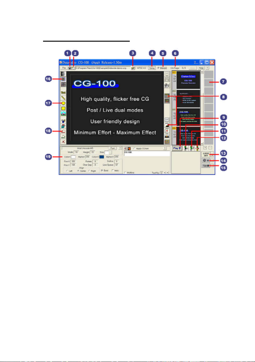
CG-100 Interface
1). Save File
2). New File
3). Open File
4) .Setup
5). Margin setting
6). Page Info
7). Clip Board
8). Animation tools
9). Playback by sequence
10). Insert an empty page
11). Copy a page
12). Delete a page
13). Logo On/Off
14). Clock / Timer
15). Targa sequence
16). Extra Editing tools
17). Graphics tools
18). Editing tools
19). Text and Image Editing window
These are all the basic function descriptions. For more detailed
information and application, please read through the rest of this
CG-100 user manual.
13
Page 14
System Set Up
TV system selection
The CG-100 can be set for either NTSC or PAL. It can also be set
as either 4:3 or 16:9. When choosing NTSC, the TV screen
resolution is 720 x 486 pixels. When choosing PAL, the resolution
will become 720 x 576 pixels. However, on the PC side, there is no
difference between PAL and NTSC, the screen W/H is just 4:3 or
16:9. When using the CG-100, you must keep in mind that the
pixels on the PC screen are not the same as on the TV. The
following picture is how CG-100 looks when 16:9 is selected.
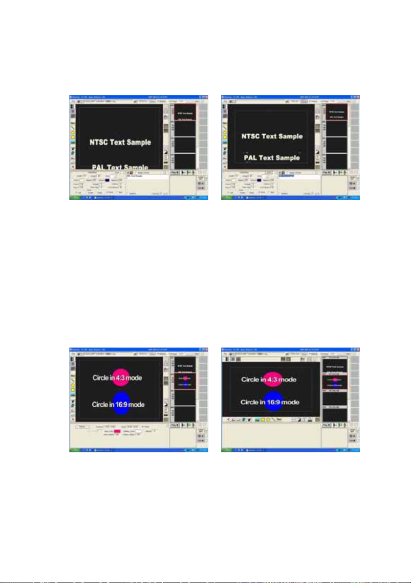
Difference between NTSC and PAL
Although the resolutions of NTSC and PAL are different, the ratio of
their widths and heights are the same. You should use the concept
of coordinates. If the y-coordinate of Title A is 243, for NTSC, the
height of NTSC is 486, Title A is in the middle. But for PAL, the
height of PAL is 576. Title A would appear in a higher position. See
the example below. On the other hand, Title B is placed at the
bottom of a PAL screen, but it would be lower, and possibly outside
of the visual screen area when it is changed to the NTSC mode.
14
Page 15
Title A in NTSC mode is in the
Title A is higher when the mode is
middle
Title B is out of the Safety Margin in
NTSC mode
changed to PAL
Title B is in the normal screen
position in PAL mode
Display mode 4:3 or 16:9
Neither 4:3 nor 16:9 will change the resolution of the PC monitor.
Therefore, while transferring a circle from 4:3 to 16:9, its shape will
be changed from a round circle to an ellipse. Please see the
example as below.
15
Page 16
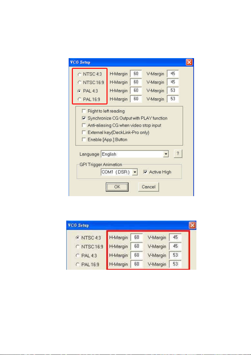
Set Video Standard
Go to SET UP, Click on the required video standard. The application
needs to be re-started if changes have been made.
Set Margins
Type the pixels to be deducted for horizontal and vertical margins
16
Page 17
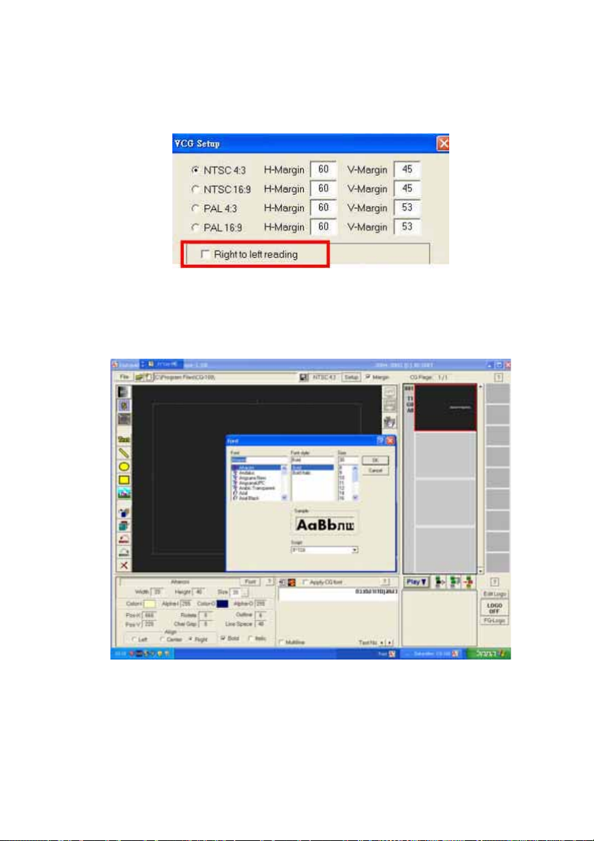
Right to left reading
CG-100 enables typing for left to right and right to left. For Right to
Left reading you need to tick the check box “right to left reading”
Be aware that you need to select appropriate fonts especially for
Hebrew or Arabic to have the editing direction from right to left. For
example the question mark “?” will be placed at the left side while
choosing Hebrew fonts.
17
Page 18
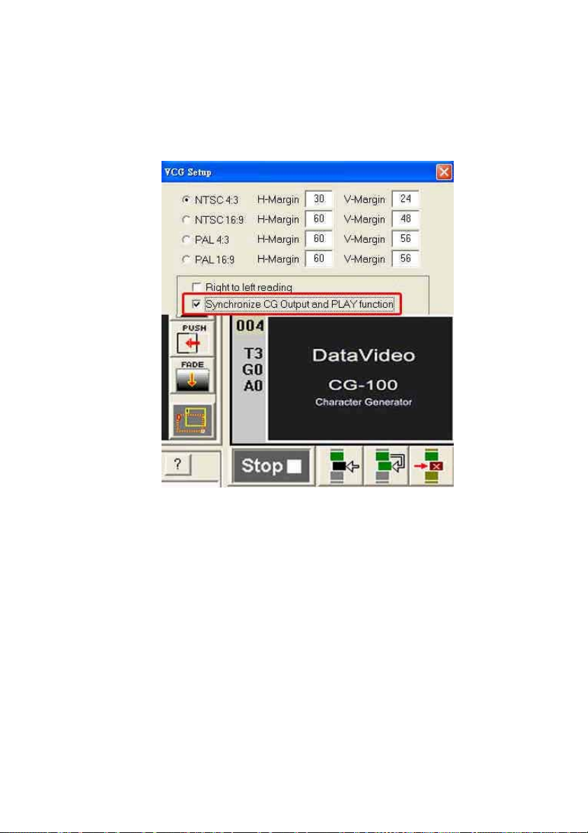
Synchronize CG output, PLAY function
When this selection has been ticked, the CG output will be cleared
when clicking stop. i.e. it does not appear on the video out.
This function needs to be enabled when using live mode.
18
Page 19
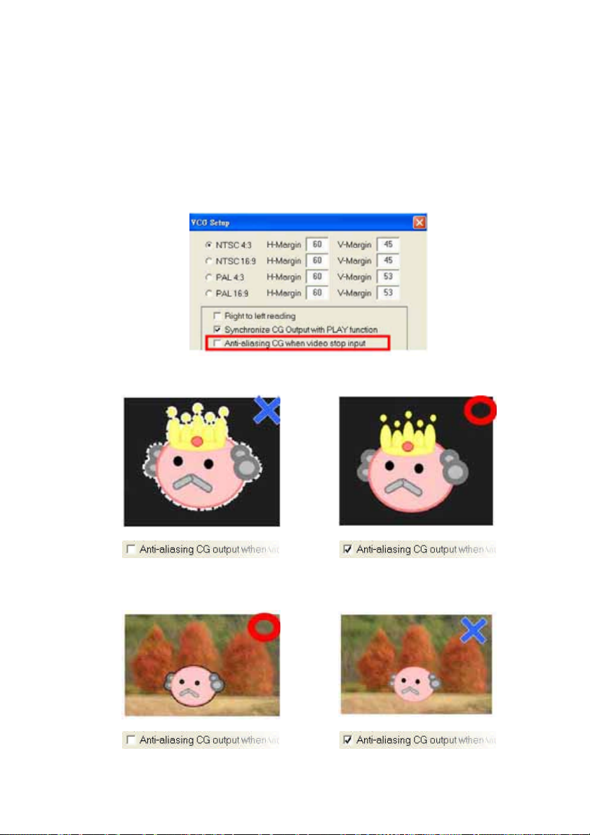
Anti-aliasing CG output when there is no
video input
The Black Magic DeckLink card does not process Alpha channel if
there is no video input. If there won’t be video input, and you want to
output the computer graphics and text just for presentation etc.
Remember to tick the check box: “Anti-aliasing CG output when
video stop input” to ensure the quality.
Without Video Input
However, on the contrary, if there is video input, do not tick the
check box.
19
Page 20
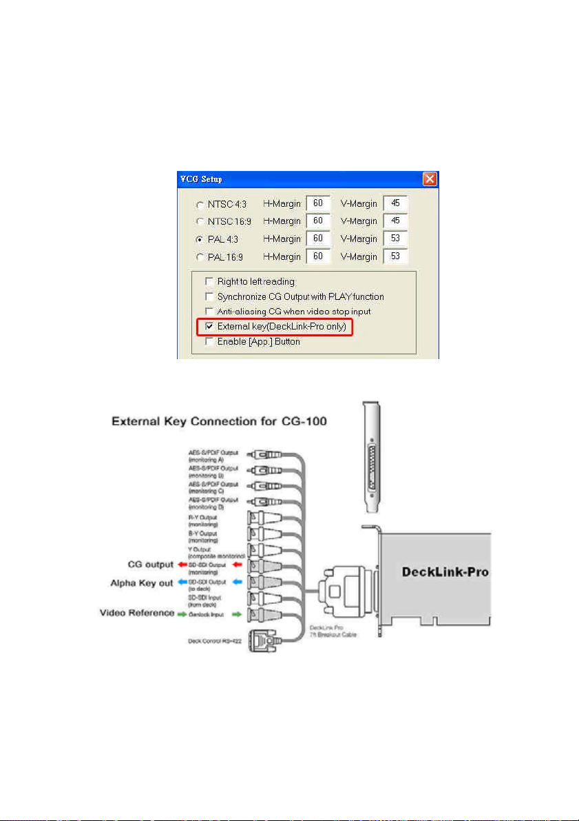
External Key
Tick the check box: “External Key (Decklink Pro only)” There is Alpha
Key out for Live Video and CG merge externally. The function only
works for Decklink Pro card.
20
Page 21
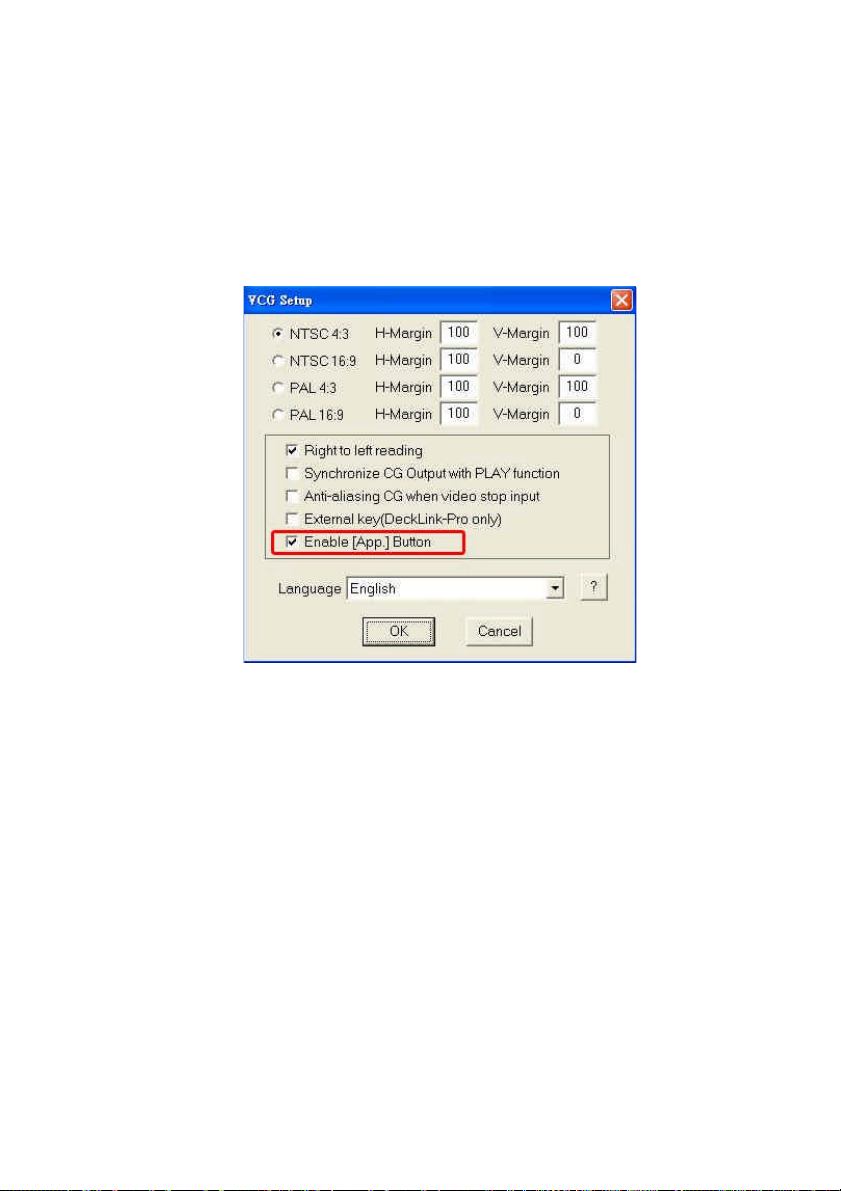
Enable [App] button
To enable a special plug-in application of CG-100, please go to
SETUP and tick “Enable [App] button”. If you do not want this plug
in, tick it off so that the App. Button box is empty.
21
Page 22
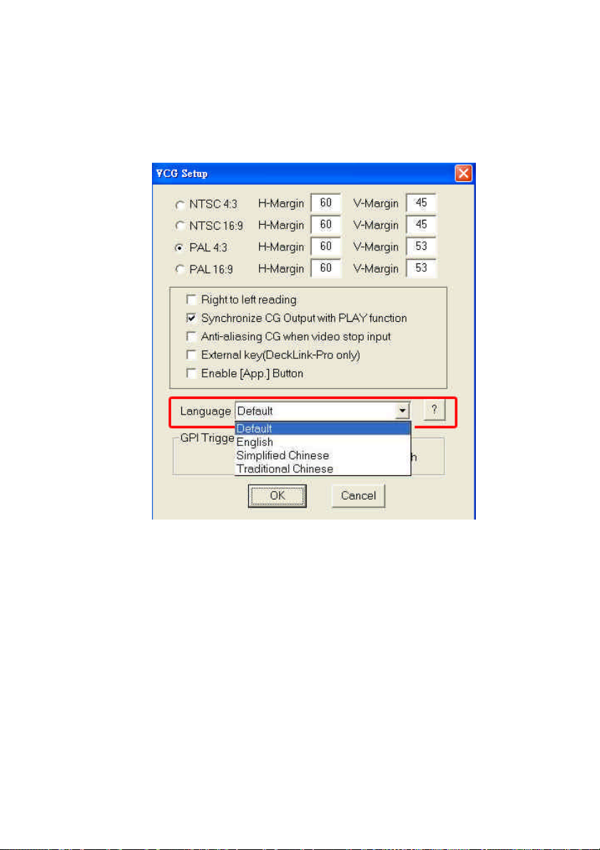
Language setting
Select one language setting for your user interface. The software
needs to be restarted after setting.
22
Page 23
GPI Trigger
You can set GPI to trigger the Animation objects like wipe, push,
fade etc in CG-100.
Follow the steps below to set “GPI trigger”
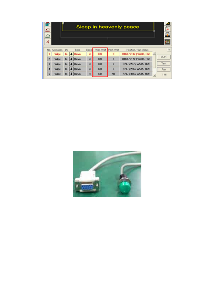
Step1 Set “ Wait until keyboard” for the “Prior_Wait” and
“Post_Wait” of all animation objects. Please note that between 2
animation objects, you do not have to set double “Wait until
keyboard”. For example, Animation A is set “ Wait” for the
“Post_Wait”. If its follower: Animation B is also set to “ Wait” for the
Prior_Wait”, there will be 2 “Wait” in between. The user would
have to send 2 GPI triggers to continue the motion. It is not a good
setting and it tends to confuse the operator. Just remove one
“Wait” and set “0 second” instead.
23
Page 24
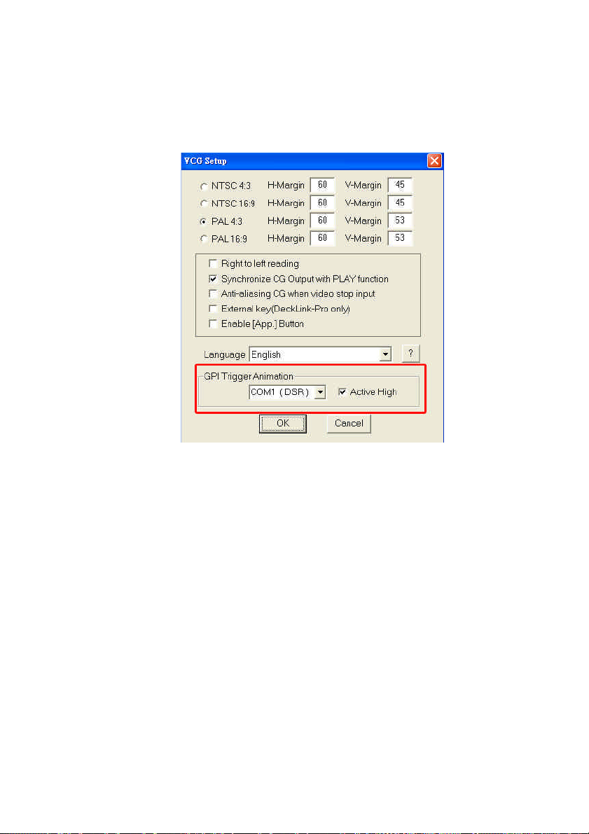
Step2. Go to [Setup] dialog in [GPI Trigger], select from COM1
to COM4 to choose one of the Serial Port DSR signal lines.
Connect the hardware of GPI (General Purpose Interface) to the
selected COM port.
Step3. Tick Active High, this means when the DSR signal is
High Voltage, the next animation will be triggered. Off Active High,
means when the DSR signal is Low Voltage, the next animation
will be triggered.
Step4
Method1 If your GPI is a switcher, the easiest way to connect
GPI to COM port is to connect the ON/OFF point (line) directly to
the 4th pin (DTR output) and the 6th pin (DSR input) of 9-pin
COM Port socket. In this case, please go to [Setup] and tick
[Active High].Therefore, when GPI switches ON, the positive
Voltage from DTR output goes to the DSR and it becomes High
Voltage, so that it can trigger the animation objects set as “Wait
until keyboard” in CG-100. The connection cable of the GPI can
24
Page 25

be up to 10 meters.
Method2 If your GPI is a photo transistor, please note the
direction of electric current is from the 4th pin (DTR output) of
COM Port 9-pin socket to the 6th pin (DSR input). When the
ON/OFF points of the photo transistor are connected in an
opposite way, the GPI will not function properly.
Method3 If one of the GPI ON/OFF points has to be grounded,
then you have to place a 1 kO resistor between the 4th pin (DTR
output) and the 6th pin (DSR input) of the COM PORT 9-pin
socket. Meanwhile, the GPI ON/OFF points should be
connected to the 6th pin (DSR input) and the 5th pin (GND). In
this case, the Active High in [Setup] dialog should be “OFF” for
Active Low setting.
25
Page 26
Tools, Effects
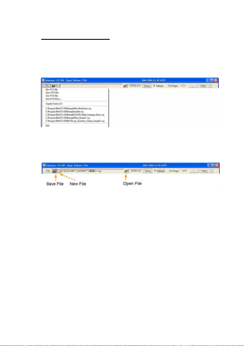
Files
The file format for CG-100 is *.vcg. Click the [File] button to display
the “File” drop down menu options.
Alternatively, you can also use the following buttons to open, save, or
select a new *.vcg file.
26
Page 27
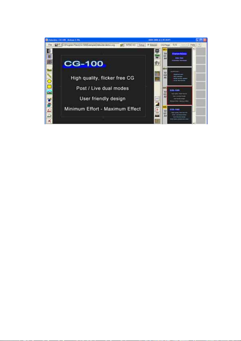
Pages
Each *.vcg file can include many “Pages”. Every page may contain
3 kinds of objects: text, graphics and animations. All the pages in a
*.vcg file will be shown to the right side of the page area.
The pages will be created in the selected aspect ratio, either 4:3 or
16:9.
The following image explains how the pages of a .vcg file will
appear in preview form on the right side of the screen.
27
Page 28
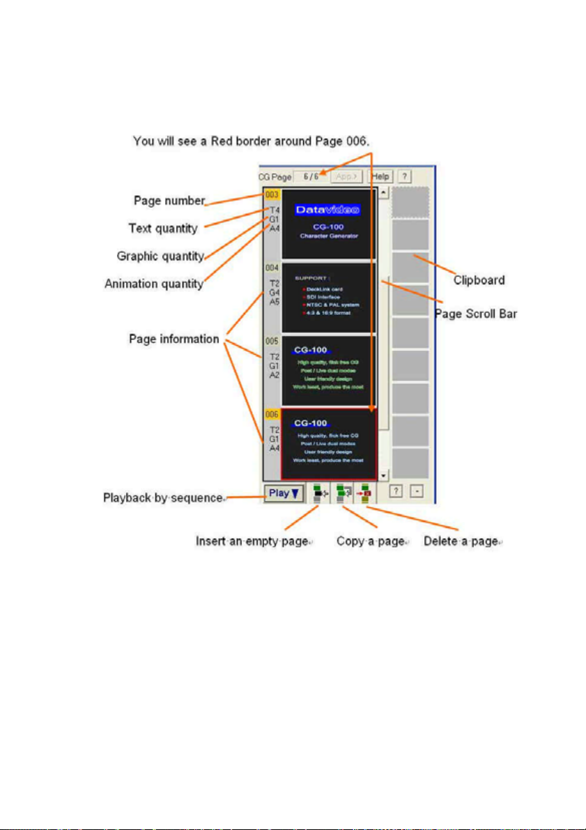
The current page is the sixth page and there are six pages in total.
28
Page 29
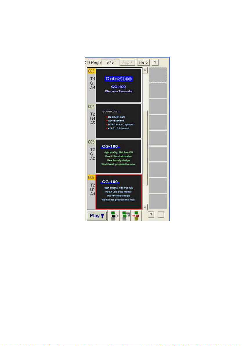
There is a different layout showing the page information. It is on the
top of the page icon.
When a new CG file is created, 4 blank pages will automatically
appear in the Page Area. Click to select a page. You will see a Red
border around the page. The highlighted page is the page that is
currently in use.
You can edit pages by inserting, deleting, copying or pasting the
pages into the clipboard. For swapping the pages, just click the
target page and drag it to the destination. (Note: the page will not be
actually moved until you drag it over half a page.)
29
Page 30
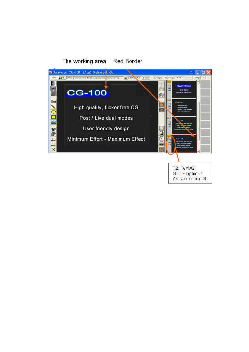
Objects
There is a Red Border around the page that is currently in use, i.e.
the one in the working area.
There are 3 CG objects in the working area:
2 text objects and a graphic bar.
The 1st text object = “CG-100”
The 2nd text object = “High quality,”
The 1st graphic = a blue bar
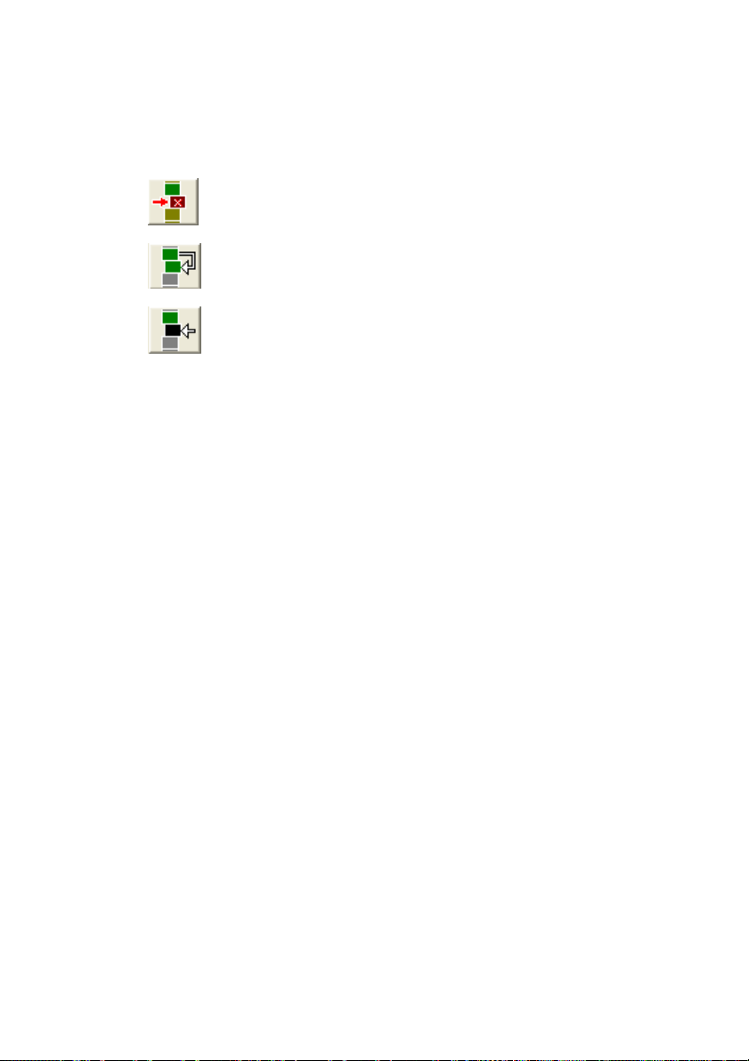
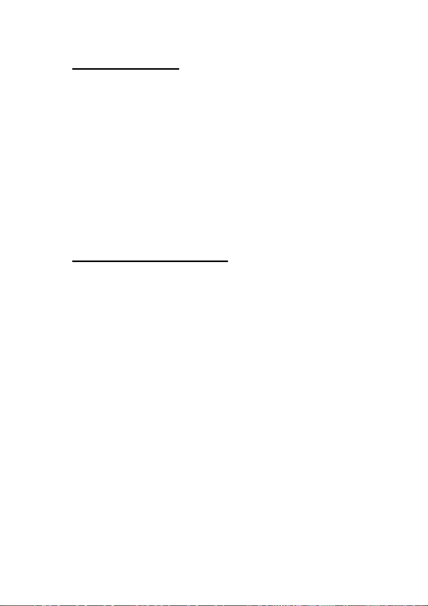
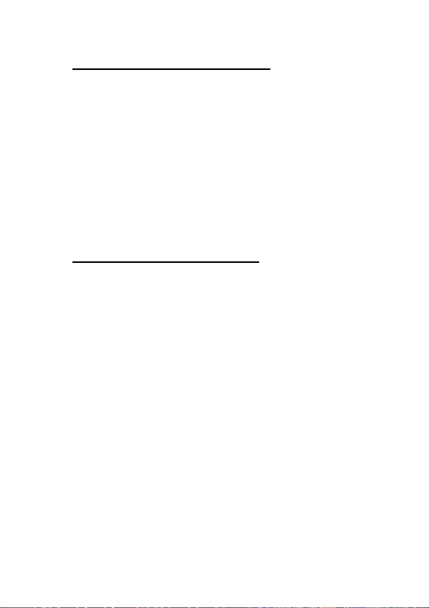
You can treat CG editing as sticking stickers on paper. For example,
3 CG objects are just like 3 stickers. Look below to see how easy it
is.
Add a new sticker
Remove the sticker
Move the sticker
Adjust the order of the stickers
Add a new CG object
→
Delete the CG object
→
Change the position of the CG object
→
Alter the sequence of the CG objects
→
Resize the CG object
Edit the CG text
30
Page 31

Layout Tools & Animation Tools
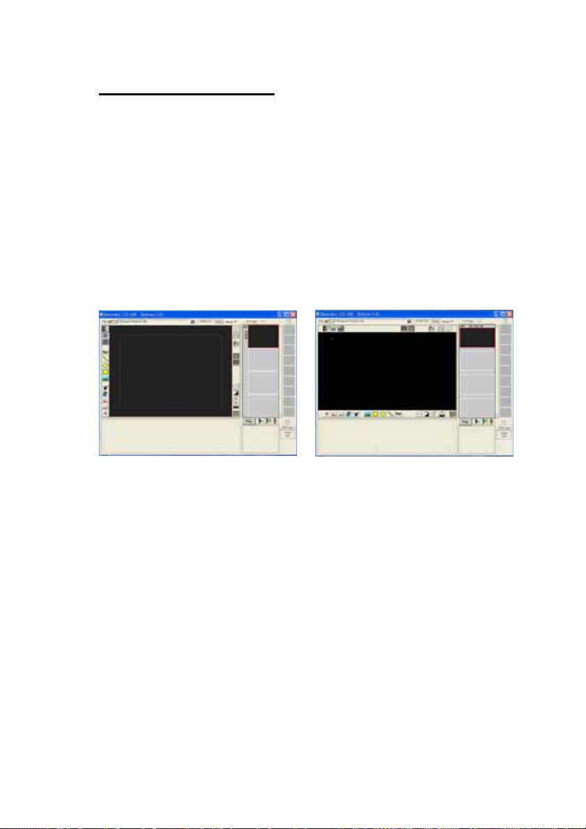
CG-100 offers the following editing tools:
In 4:3 mode, “Editing” Tool bar and “Animations” Tool bar are as
below:
In 16:9 mode, “Editing” Tool bar and “Animations” Tool bar are as
below:
31
Page 32

Parameters Panels
The CG-100 provides 5 editing tool-buttons for you to add Text,
Bars, Rectangles, Ellipses and Images. You can go to the
Parameters Panels to set the colors of text, the precise positions
etc. Please see the following example:
Text Parameter Panel (1)
Text Parameter Panel (2)
32
Page 33

Text Parameter Panel (3)
Graphic Parameter Panel
Image Parameter Panel
Animation List
The CG-100 provides 4 kinds of animations. You can click on the
buttons to insert a Display, Wipe, Push or Fade effect. After
inserting an animation effect, it can be edited on the Animation List
Editing Panel.
33
Page 34

Layout Editing
The CG-100 Layout is composed of 5 elements including text,
graphic bars, rectangles, ellipses and images. To edit the CG
Layout, you should do the following: Press one of the buttons on
the tool bar to insert a new object.
Drag the object to the required position and if necessary, resize it.
Set parameters on the Parameters Panels. If necessary, you can
cut, delete, and adjust the sequences among objects.
Text Editing
This is the way to insert a text object:
(1).Click Text button on the tool bar
A text object will be created in the working area.
34
Page 35

Normally, the text content is as same as the previous one.
Otherwise, a default “VCG Sample” will be used for the first text
insertion.
(2). Drag the marks around the text object
The current editing text object will be surrounded by 4 marks:
(3). To Move a text object
Place the cursor on the text object, but do not put the cursor on
any of the 4 marks. Press and hold the left button. This will make
the cursor become a Drag Symbol, which means the text object is
selected and ready for editing. Hold the left button down and move
the mouse, the text object will follow the mouse.
Once the text is in the right place, release the left button. The
meshed surface allows you to see other objects through the
selected one while it is moving over them.
35
Page 36

(4). Fine-tuning the position of Text Object
It is hard to move just a pixel or two by using the object drag
function. In this case, you can press the [?][?][? ][? ] buttons.
Every single press moves the text object one pixel in the chosen
direction.
Note: While typing, the [?][?][? ][? ] buttons are for moving the
cursor. If you want to use the [?][?][? ][? ] buttons for moving the
text object, you have to use them immediately after dragging the
object approximately into position.
(5).To Resize a Text Object
(6). To Adjust the Gaps between letters (Kerning)
Press dual-squares and move the mouse horizontally – Right to
increase and Left to decrease.
36
Page 37

(7). To Rotate a Text Object
To rotate the object left click on the circle, hold the left button down
and move the mouse vertically.
37
Page 38

(8). Content of Text Objects
You can type the content of the text objects in the typing area
under the working area.
Change the content here in the typing area
38
Page 39

A text object literally means a single-line. When you’ve finished
typing, press [enter] to update the target text object. The below
example shows how to change “CG-100” into “CG String Sample”.
Clicking the [Update] button, this will apply the alterations to the
text object. Part of the object may now be outside of the working
area. Select the object and reposition it.
To avoid this situation, please set the alignment properly before
updating the text object.
39
Page 40

The three kinds of alignment will affect the position when the
latter text is longer or shorter than the original text.
The text object will be updated as soon as you click [Update].
(9). Multi-line Text Objects
You can create a multi-line text object, just like a paragraph. Tick
[Multi-line] to enable this function.
40
Page 41

With Multi-line selected the typing area will be extended, so that
you can type a whole paragraph.
CG_100 auto updates the text when the text changes.
Note: When typing multiple lines, the [Enter] key will go to the
next line to update data.
41
Page 42

The following is the result of text changes
:
42
Page 43

(10). Save Text Styles
When you create a text object and want to save its style as a
sample, just click the Style button to open the [Text Styles] panel.
Step1: Colors, fonts, outline and thickness can be stored in the
“Style Panel”. Click this to open the “Style Panel”.
Step2: Click to select a place for storing the style.
43
Page 44

Step3: Back to select the text line on the working area.
Step4: Click this button to store the text style in the selected place.
Step5: Save all styles into a file.
44
Page 45

(11). Apply a Style
First click to select the text object.
Then double click one of the styles on the panel. The style will be
applied.
45
Page 46

(12). Text Parameters Setting
You can set the parameters in the Text Parameter Panel.
Click [X] to close the window.
The text parameters Panel comes back immediately.
The parameters are:
Font
Width
Height
Pos-X
Pox-Y
Color-I
Alpha-I
Rotate
Char Gap
Color-O
True Type fonts, click the button to select other
-
fonts.
The width of letters. Press left button, move the
-
mouse horizontally.
The height of letters. Press left button, move
-
vertically.
X field of the text object. Press left button, move
-
horizontally.
Y field of the text object. Press left button, move
-
vertically.
The fill color . Click the color to select other
-
colors.
The opacity of the fill. Press left button, move
-
horizontally.
Rotate the text object. Press left button, move
-
horizontally.
Gaps between letters. Press left button, move
-
horizontally.
The color of the outline. Click the color to select
-
46
Page 47

other colors.
Alpha-O
The opacity of the outline. Press left button, move
-
horizontally.
Outline
The border of the text object. Press left button,
-
move horizontally.
Line Space
Only for Multi-line text objects. Press left button,
-
move horizontally.
Align Left/Top
Set the Axis of the text object (the cross
-
mark) to the left/top. Words add from left to right,
top to the bottom.
Align Center
Set the Axis of the text object (the cross
-
mark) in the center. Words go from left to right,
top to bottom.
Align Right/Bottom
Set the Axis of the text object (the cross
-
mark) in the center. Words go from
left to right, top to bottom.
Bold
Italic
You can set the text objects’ parameters in the relative dialog
Tick to make the fonts bold-faced.
-
Tick to make the fonts Italic.
-
boxes. Tick to select bold-faced fonts or three ways of alignments.
Other parameters can be set by way of press left button and move
horizontally.
For example, if you want to set the transparency of a text object,
follow the steps below:
Place the cursor on the number box of “Alpha-I” item.
Press left button to change the shape of the cursor [two-side
arrows]
Press left button and move the mouse horizontally to change
the level of transparency.
You can see the target object changes its opacity immediately on
the working area.
47
Page 48

(13). Vertical Text Object
For some Asian languages, sometimes text goes vertically. If you want a
vertical text object, follow the steps below,
Open [Font] dialog box. Select the font whose name starts with @.
Set the parameter of [Rotate] to 270°.
Note: Double click the number box of the [Rotate] item. The program will
set the default angles which are as below:
For fonts whose name starts with @, the default angle is 270°.
For all other fonts the default angle is 0°.
Default width of a letter
The default width of a letter for Windows PC is a half of its default height.
If you want to return its default setting, please double click the number
boxes of [Width] or [Height] items.
Double click [Width] item, the width will be 1/2 of its height.
Double click [Height] item, the height will be 2 times its width.
48
Page 49

(14). Importing text from a text file
If you need to use a large amount of text or text in foreign
languages, you can import the text from a file. The CG-100 allows
you to import text from a *.txt file.
Step1: Click this button to open text import panel.
49
Page 50

Step2: Create a default text object and select it.
Step3: Open a text file. Highlight the required text.
Step4: Click this button
to output the text.
50
Page 51

The result is just like below.
51
Page 52

Inserting a Graphic Bar or a Line
Click this button to insert a bar or a line.
There are 2 square marks on both ends of a graphic bar/ line. You can
hold on either side to alter the bar/ line.
52
Page 53

The parameters of the graphic bar/ line can be set on the following
panel.
Bar Width - the width of the graphic bar/ line, press left
button and move the mouse horizontally
Outline - the thickness of its outline, press left button and
move the mouse horizontally
Inner Color - the fill color, go to a dialog for further setting
Outline Color - the outline color, go to a dialog for further setting
Inner Alpha - the opacity of the fill, press left button and move
the mouse horizontally
Outline Alpha - the opacity of the outline, press left button and
move the mouse horizontally
53
Page 54

Many kinds of Graphic Bars/ Lines:
54
Page 55

Inserting a Rectangle or an Ellipse
Click this button to import a rectangle
To move this rectangle, click the inner part then move it.
To resize the rectangle, click the square on the bottom right and
move it around.
Click this button to import an ellipse.
To move this ellipse, click the inner part then move it.
To resize this ellipse, click the square on the bottom right then
move it around.
55
Page 56

Parameters Panel for rectangles and ellipses.
Outline - the thickness of its outline, press left button and
move the mouse horizontally
Inner Color - the fill color, go to a dialog for further setting
Outline Color - the outline color, go to a dialog for further setting
Inner Alpha - the opacity of the fill, press left button and move
the mouse horizontally
Outline Alpha - the opacity of the outline, press left button and
move the mouse horizontally
Many Kinds of Ellipses and Rectangles:
56
Page 57

Inserting an Image
Step1: Click this button to insert an image object.
Step2: Click “File” to select an image file. The image will be shown
on the working area.
57
Page 58

Step3: Click the inner part of the image to
move the image.
Step4: Press the square on the
bottom right to resize the
image.
58
Page 59

Step5: The image selecting panel is a
Image File path - shows the path of the image file
Open - to open a dialog box for image selection
Position - the position of the image
Size - the size of the image (pixel by pixel)
Alpha - the opacity of the image
Color Key - tick to enable color key function.
Key Color […] - to designate a color for keying, which
will become totally transparent.
s follows
:
The transparency of an image
When you set the transparency of an image, the setting is applied
to the whole image. The levels of transparency are from 0 to 255.
0 is fully transparent while 255 is fully opaque. If the image format
is targa 32 bit, then the transparency set here will multiply by the
files original alpha. (Note: Some applications such as Adobe
Photoshop allow users to create targa 32bit image.)
A Targa
Alpha=255 Alpha=85
59
Page 60

Select a color to be transparent
Step1: Insert the bmp file. Tick [Color Key]
Step2: Press the button
a dropper.
to turn the cursor into
60
Page 61

Step3: Place the dropper over the color that will be transparent.
Click left button to select the color. You can adjust the number
to remove the background.
Step4: The selected blue color becomes transparent.
Extra Editing Tools
The CG-100 provides extra editing tools that make editing more
convenient.
(1). Background button
The default background of the working area on the CG-100 is
black. However, if a title is very dark or the outline has to be black,
it cannot be seen clearly with the black background. So the
[background] button allows you to change the background color.
When you click the button, the background will be changed from
black, dark gray, gray, light gray to white. It goes around as a loop.
61
Page 62

Please see the following examples:
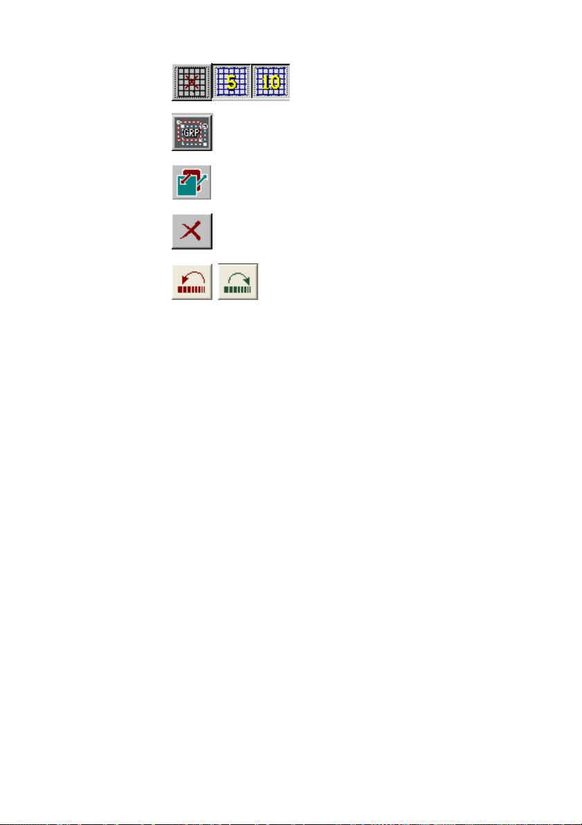
(2). Grid button
The grid makes aligning objects much easier. When you click the
[grid] button, it goes around as a loop from X? 5? 10. The [X]
means the grid function is disabled. The [5] means the squares are
5x5 pixels. The [10] means the squares are 10x10 pixels.
(3). Group button
Click the [group] button to display the group menu with the
following options.
(4). Top/ Bottom
The objects on the CG-100 working area are placed in the order
they were created. The first insertion is on the bottom and the last
one is on the top. Of course it doesn’t matter if there is no
overlapping. However, if more than two objects overlap, the Top /
Bottom button enables you to put the layers in the right order.
Click to select an object on the working area.
Then click the [Top / Bottom] button.
Every click moves:
The front object to the back
The lower objects all move one layer forward.
62
Page 63

(5). Delete
Click [Delete] to delete a selected object.
(6). Undo / Redo
Cancels or retrieves the last applied effect or command; i.e.
reverts to previous attributes.
63
Page 64

Group Move/Zoom
Click [Group Move/Zoom] button, There will be 2 boxes, the blue
one and the red one. The red box, the source box, is to select the
source object/s - usually more than one object. The blue box, the
destination box, is to place and resize the result. If the red box is
as big as the blue box, then the group of objects is just moved to
another place. If the blue box is not equal to the red one, that
means the group of objects will be moved and resized.
To perform this function, you need to place the cursor on the
squares on the source box or on the destination box as below,
The following is a group of CG objects which include a water lily
image, a green bar and a text object, “VCG Sample”.
64
Page 65

If you want to enlarge the whole group, the steps are as follows:
a.) Place the cursor on the top left side. Drag the red box to
encompass the objects.
b.) Drag the red FRAME to the top left side of the group of objects.
c,) Place the cursor to the bottom right of the red box. Then drag to
resize the box
65
Page 66

f.) Then place the cursor to the top left side of the blue
box.
g.) Drag to move this blue box to the destination.
h.) Put the cursor on the bottom right. Drag to resize the blue box.
i.) Drag to resize the blue box. The size of this blue box represents
how big the whole group will be.
66
Page 67

j.) When all the adjustments are done, click the annulus to finish
and display the result.
The original group
k.) You will see the whole group has been enlarged to the size of
the blue box.
The result after
executing [Group
Move/Zoom]
If you want to undo this function, just click the [Group Move /
Zoom] button again to revert to the original settings.
67
Page 68

Group Copy/Cut/Delete
After clicking the Group button, select one of the options: [Group
Copy], [Group Cut] and [Group Delete]. These functions all create
a blue and white outlined box on the working area. Place and
resize the box to surround the target objects. Then you can copy,
cut or delete the objects inside the box
Unlike when cropping an image, the CG-100 will copy, cut or
delete the entire object instead of a portion of it. So, when the blue
and white box only surrounds a part of an object, the CG-100 will
verify whether the center of the object is inside the box. If so, the
object is selected. If not, it is not selected.
Once the blue and white box is surrounding the target objects,
click the annulus to start copy, cut or delete. Below is the result
after doing cut/ delete
The copy function allows you to copy the group of objects to the
CG’s clipboard.
There are 10 spaces to store them. If you want to retrieve the
group objects, click the clipboards to paste the group in the
original position on a page.
68
Page 69

Animation Editing
The CG-100 offers various animations such as Display, Wipe,
Push, and Fade; also Roll and Crawl to scroll text across the
screen or up the screen.
Setting an Animation Box
Display, Wipe, Push and Fade, each of the four animations has a
box and a set of parameters. You should regard the working area
as two dimensions. Select any part of it to do the animations
Here is an example with 3 single-box animations:
The 1st animation box – “VCG” is selected and set as Display-In,
pressing any key will activate this
animation.
The 2nd animation box – “Sample” is selected and set as
Wipe-In-Right.
The 3rd animation box– “VCG Sample” is selected and set as
Fade Out, pressing any key will
activate this animation.
69
Page 70

As long as the animation box is put on the working area, the detail
of the animation will be shown on the animation list which is
beneath the working area.
The parameters of the animation list are:
No - the number of the animation
Animation - Select an animation like Display, Wipe, Push or
Fade. Click the right button here to change to a
different animation.
I/O - In/Out, shows whether the animation is affecting
the way the object appears or disappears; i.e. A
Fade In – fades the object in, and a Fade Out –
fades the object out. Click the right button here to
select in or out.
Type - The direction of an animation. Click the right button
here to select different movements.
Speed - Determines how fast an animation moves. Click the
right button here to select a different speed - The
higher the number the faster the speed.
Prior Wait - Determines how the animation will be triggered.
Click the right button here to select different ways.
For example, this may be a time delay or a key
press.
Post Wait - Determines how you want to proceed to the next
animation. Click the right button here to select
different ways. For example, this may be a time
delay or a key press.
Position - the x, y coordinates of an animation box. Click the
right button here to position the animation box.
You can only use one animation at a time from the animation list.
The current one on the list is highlighted in yellow with red words.
The corresponding animation box is also highlighted in red and
yellow.
70
Page 71

To Edit Animation boxes, please follow the steps listed below:
Step 1. Use this button
Step 2. Make animations by using the buttons.
Step 3. Click here to show all animation boxes.
to make an object.
Step 4. Make sure to adjust the animation box properly to fully
cover the target object.
71
Page 72

Step 5. All the animations will be listed as below. Change the
attributes by clicking the RIGHT BUTTON to launch the dialog for
further settings.
Step 8. Play all animations
page by page
( Duplicate an animation
box.)
Step 6. Test a selected
animation
Step 7. Run all animations
on this page.
72
Page 73

To add a [Display] Animation
Display is a basic animation. Click [Display] button to create a red
and yellow outlined animation box on the working area.
As you create the display animation, it will appear as a row in the
list. Then drag the animation box to include the CG-100 objects.
73
Page 74

Place the box right around the title.
Set the parameters on the list
You can select [Display] [In] or [Out]. [In] means to show the area,
[Out] means to hide the area.
The default setting of display is [Display-In]. Put the cursor on the
[In] field and click right button to select [Out] from the pop-up menu
as shown below
Select [In] or [Out] to finish the setting
74
Page 75

[Display] requires no settings for [Type] or [Speed] but you will
have to set the [Prior Wait] and [Post Wait] settings. If you tick the
“Wait to hit key” on the [Prior Wait] the animation will not start until
you hit the Ctrl key on the keyboard. To do this, place the cursor on
this field and click the right mouse button to open the pop-up dialog
for setting.
In this field [Prior Wait], you can also select a wait time in seconds
before the animation starts
In this example, we have chosen [Wait Hit Keyboard]. Click [OK] to
finish the setting
[Post Wait] defines how to wait after doing an animation. To set the
[Post Wait] setting, place the cursor on this field and click the right
mouse button to open a pop-up dialog as below,
You can either type the [Post Wait] value directly or click the
buttons to set the seconds. Click [OK] to finish the setting.
75
Page 76

Finally, click the right mouse button on the field of [Position], the
cursor will switch to the top left side of the animation box on the
working area so that you can drag to resize the animation box.
To add a [Wipe] animation
Click [Wipe] on the tool bar to create a new Wipe animation box. If
there is an existing animation, you can also click the [Duplicate]
button and then change its parameters to become a [Wipe].
To duplicate a row of animation
Place the cursor on this field and click the right mouse button to
open a pop-up menu.
Select [Wipe] animation
You will need to set the [Type] and [Speed] for the wipe animation.
Place the cursor on the field of “Type”, click the right mouse button
to open the pop-up dialog.
76
Page 77

In the [Wipe Type] dialog box, select the wipe you require. In this
example we selected a right direction wipe. The Type field in the list
confirms the setting.
In the [Speed] field, right click the mouse to open the pop-up menu.
Choose the required speed. Then the setting is finished.
You can estimate the time an animation will take as follows. If the
animation box is 120 pixels wide and the speed of WIPE is 4 pixels
per frame, then it will take 30 frames to run this animation. In NTSC
mode, it takes 1.0 second, while in PAL mode, this will take about
1.17 seconds.
Note if you have a second wipe and do not set a “Prior Wait” time
then it will appear immediately after the previous wipe “Post Wait”
time. If you do select a “Prior Wait” time then there will be both the
77
Page 78

previous wipe “Post Wait” and the second wipe “Prior Wait” time
added together. A flexible way to trigger the entrance and exit of
“Wipe” animation is to Tick [Wait Hit Keyboard] and let the operator
decide when to start or end the animation
Place the cursor in the Position field here then right click the mouse
button to resize the WIPE animation box
To add a [Push] animation
Follow the similar procedure as in making a [Display] or a [Wipe]
animation. You can click [Push] on the tool bar to create a new
PUSH animation box. If there is an existing animation, you can click
[Duplicate] then change its settings to become [PUSH].
Unlike [Display] and [Wipe], [Push] cannot be used to preserve the
screen on the last page even if you set the page’s attributes as
reserve last page. See below the difference between [WIPE] and
[PUSH].
78
Page 79

[WIPE] with Reserve Last screen
The first example shows the first page contains a Display
animation, then the second page contains a wipe animation, and
this page reserves last screen. When the two pages play back, the
blue box won’t be cleared.
79
Page 80

[PUSH] with Reserve Last Screen
The second example also sets first page to have a [Display]
animation, then the second page contains a push animation, and
this page reserves last screen. But this time, when the two pages
play back, part of the blue box will be cleared in order to push the
selected CG area in.
80
Page 81

To add a [Fade] animation
Adding a [Fade] animation is just as same as adding other
animations mentioned above.
To insert a [FADE] animation, click the [Fade] button or first
duplicate the previous animation then change its attribution to be
[FADE].
To delete an existing animation, simply select the animation box
and press the delete key on your keyboard or right click the mouse
and select delete from the pop up menu.
To change the sequence of animations, select one of the
animations on the list and simply drag it to the desired position in
the sequence.
81
Page 82

Roll and Crawl
To Roll a List
The CG-100 provides the Roll function to roll a text list.
Step1: Click this button
Please be aware there can be only one Roll or Crawl object in a
page
The limitation of a ROLL object
There is only one Roll or Crawl object in a page.
A Roll object can’t be longer than 10 pages’ in height.
Step2: To edit a Roll object, click the object in the working area.
to create a Roll page.
Step3: Define the Roll object in the roll object panel.
82
Page 83

Step4: To set a dual string roll object like the sample on the panel,
use // to separate 2 strings on every line. The part on the left of // is
one string and the part on the right is another string. Set different
color, fonts for the strings using [style-1] and [style-2] button.
83
Page 84

For further settings of the Roll object panel, please see below
Tick [Dual Style] to create a single string roll object or a dual string
roll object.
Click [style-1] or [style-2] button to edit the parameter of the string
To return to the Roll object panel, click this button.
To return to the Roll object panel, click this button.
To import text from a txt file, click [Note Pad] to open the file and
select the part copy and paste the part to the editor on Roll object
panel.
Click [update] button when you
import text from files
When the Roll object has been altered, click [Play] to run the Roll
object.
84
Page 85

To adjust the size of a Roll Object
The size of a Roll Object is adjustable.
Step1: Use the cursor to resize the Roll object.
Step2: Move the Roll object to the required position.
85
Page 86

Step3: press [Style-1] or [Style-2] to adjust the position and other
attributes of the strings.
Style-1
Step4: Move the right part of the string by adjusting the parameter
of X-position
86
Page 87

Style-2
Step5: Move the left part of the string by adjusting the parameter of
X-position.
Step6: Place another text object on the screen and create an animation
box for the text object. Arrange the sequence
87
Page 88

To adjust the size of a Crawl Object
Step1: click this button to create a crawl object
Please be aware there will be only one Roll or Crawl object in a
page.
The limitation of a Crawl object:
There is only one Roll or Crawl object in a page.
A Crawl object can’t be longer than 10 pages’ in width.
88
Page 89

For further settings of the Crawl object panel, please see below
Tick [Dual Style] to create a single string crawl object or a dual
string crawl object.
Click style-1 or style-2 button to edit the parameter of the string
To return to the crawl object panel, click this button.
To import text from a txt file, click [Note Pad] to open the file and
select the text to copy then paste it to the editor in the Crawl object
panel.
Click [update] button when you
import text from files
When the Crawl object has been altered, click [Play] to run it.
89
Page 90

Live CG Editing
You can add CGs while doing post production. But what if you
want to work with live video programs? You have to handle all
kinds of situations during video shooting.
Live editing mode provides great flexibility to rise to the occasion.
Pressing this button
same time: (To immediately alter other CG pages while one CG
page displayed live.)
it allows you to handle two jobs at the
90
Page 91

91
Page 92

Step4: Make sure the page
p
pag
r
is being output. You are
now ready to edit off-line.
Move the mouse to the
“information area” left of
the Page List, and then the
cursor will become red.
Click left button when the
cursor is red. The
background of the
“information area” will
become pink. Then the
selected page is ready for
off-line editing. All the
objects on this page will be
shown in the working area.
Live Status Panel
Page Numbe
Page U
Type of Wipe
Wait for a certain time or
a keyboard click before/
Clear the output of
this
e
92
Page 93

Whenever you want to quit the Live Editing mode, remember to
select the appropriate selection of TV-On or TV-Off.
If you don’t pay attention the final editing page may be accidentally
output after leaving the Live Editing mode. If that page is not for
output, select TV-OFF when quitting the Live Editing mode.
This page could be
accidentally output when
leaving the Live Editing
Mode. Remember to select
TV-OFF when leaving if the
previous editing page is
not ready to be output
93
Page 94

Quick Edit function
Think about this, in a talk show, the video will switch from the host
to several different guests. The layout of the page is set and there
are just some names that need to be changed. If you need to edit
something similar in a very short time, this function is really useful.
Click this button to open “Quick CG Text Editor”
which allows navigation from page to page to modify text or
duplicate similar pages in a very efficient way.
To Modify the Text
Step1: Select the page that you want to alter and click the quick
edit button. The Quick edit panel will be as below.
Text Edit
The total objects on this page. In here, there are 4 text, 0 graphics,
0 animation.
In the selected page below, we see there is a 3 line text object and
a graphic combination on it. For this example, there are 3 text
objects: CG-100. JUSOFT, Datavideo. But all of them are listed in
the Text Edit box. It doesn’t matter if there are single lines,
multiple-lines, or a mixture of them.
Current Page
94
Page 95

Step2: Place the cursor on the line to be altered. Change the
words directly.
Step3: Press [Enter] key to update CG.
Step4: If there are other pages to be modified, Press [Page up] or
[Page down] key to select the page. You can also click Up/Down
buttons to look for the desired page. Once found, repeat steps 2
and 3.
95
Page 96

Page List
Page List is to view and select different pages
Selected page
Page Number: 002
2 Text objects on page2
8 Graphics on page 2
1 Animations on page2
Total pages
Select a Page
Place the mouse to the page. Click the page when the cursor is
red. The page has been selected.
Delete a Page
To delete a page, click the page and click this button..
96
Page 97

Duplicate a Page
To duplicate a page, select one page and click this button.
Step1: Select a page.
Step2: Press [Ctrl] + [Alt] + [Insert], this duplicates the page and
text can be altered later.
So, it is easy to prepare a fixed page and use this quick edit
function to clone several pages. Then go into the Edit Text box to
change the text page by page. You are able to create many
pages with the same attributes in a very short time.
Insert a Page
To insert a page, select the page and click this button.
Alternatively, instead of clicking this button, move the mouse to the
gray area and left click, a new page will be created, too.
97
Page 98

The effect of Reserve Last Screen
Step1: Select a page. Click “duplicate page” button to clone it.
Step2: Replace the objects on the second page. Keep the second
object the same size at the same position.
Step3: Set different animations for each page. In here, page 1 is
“Push”, Page 2 is “Wipe”.
98
Page 99

Step4: Select page 002 on the page list. Click Right button to open
a Pop-up menu. Choose Reserve last screen.
Reserve last screen
We can see the effect of 002 is as below
99
Page 100

Clean last screen
Select “Clean Last Screen”, the effect on 002 will be like below
100
 Loading...