

Page 1
BLOCK CAMERA
BC-80
Instruction Manual
Page 2

2
Table of Contents
FCC COMPLIANCE STATEMENT .......................................................... 4
WARNINGS AND PRECAUTIONS......................................................... 4
WARRANTY ....................................................................................... 5
STANDARD WARRANTY .......................................................................... 5
THREE YEAR WARRANTY ......................................................................... 6
DISPOSAL .......................................................................................... 7
1. INTRODUCTION ............................................................................. 8
1.1 FEATURES ...................................................................................... 8
2. SYSTEM DIAGRAM ......................................................................... 9
3. CONNECTIONS ............................................................................. 10
3.1 FRONT VIEW ................................................................................. 10
3.2 REAR PANEL ................................................................................. 11
4. IR REMOTE CONTROL .................................................................. 14
5. OSD MENU OPTIONS ................................................................... 19
6. DIP SWITCH SETTINGS ................................................................. 29
7. RS-422 CONTROL PROTOCOL ....................................................... 30
7.1 PIN DESCRIPTIONS ........................................................................ 30
7.2 CONTROL OPERATION GUIDE ........................................................... 30
7.2.1 Overview of VISCA ............................................................ 30
7.2.2 VISCA Communication Specifications ................................ 32
7.2.3 VISCA Device Setting Command........................................ 35
7.2.4 VISCA Command/ACK Protocol ......................................... 36
Page 3

3
7.2.5 VISCA Camera-Issued Messages ....................................... 37
7.2.6 BC-80 Commands ............................................................. 38
8. DVIP CONTROL OPERATION GUIDE .............................................. 48
8.1 PHYSICAL LAYER ............................................................................ 48
8.2 GENERAL CONNECTION INFORMATION .............................................. 48
8.3 PACKET DATA ............................................................................... 48
9. FIRMWARE UPGRADE .................................................................. 64
10. DIMENSIONS ............................................................................. 65
11. SPECIFICATIONS ........................................................................ 66
SERVICE AND SUPPORT ................................................................... 68
Disclaimer of Product & Services
The information offered in this instruction manual is intended as a guide only. At
all times, Datavideo Technologies will try to give correct, complete and suitable
information. However, Datavideo Technologies cannot exclude that some
information in this manual, from time to time, may not be correct or may be
incomplete. This manual may contain typing errors, omissions or incorrect
information. Datavideo Technologies always recommend that you double check
the information in this document for accuracy before making any purchase
decision or using the product. Datavideo Technologies is not responsible for any
omissions or errors, or for any subsequent loss or damage caused by using the
information contained within this manual. Further advice on the content of this
manual or on the product can be obtained by contacting your local Datavideo
Office or dealer.
Page 4

4
FCC Compliance Statement
This device complies with part 15 of the FCC rules. Operation is subject
to the following two conditions:
(1) This device may not cause harmful interference, and
(2) This device must accept any interference received, including
interference that may cause undesired operation.
Warnings and Precautions
1. Read all of these warnings and save them for later
reference.
2. Follow all warnings and instructions marked on this unit.
3. Unplug this unit from the wall outlet before cleaning. Do not use
liquid or aerosol cleaners. Use a damp cloth for cleaning.
4. Do not use this unit in or near water.
5. Do not place this unit on an unstable cart, stand, or table. The unit
may fall, causing serious damage.
6. Slots and openings on the cabinet top, back, and bottom are
provided for ventilation. To ensure safe and reliable operation of
this unit, and to protect it from overheating, do not block or cover
these openings. Do not place this unit on a bed, sofa, rug, or
similar surface, as the ventilation openings on the bottom of the
cabinet will be blocked. This unit should never be placed near or
over a heat register or radiator. This unit should not be placed in a
built-in installation unless proper ventilation is provided.
7. This product should only be operated from the type of power
source indicated on the marking label of the AC adapter. If you are
not sure of the type of power available, consult your Datavideo
dealer or your local power company.
8. Do not allow anything to rest on the power cord. Do not locate
this unit where the power cord will be walked on, rolled over, or
otherwise stressed.
9. If an extension cord must be used with this unit, make sure that
the total of the ampere ratings on the products plugged into the
extension cord do not exceed the extension cord rating.
Page 5

5
10. Make sure that the total amperes of all the units that are plugged
into a single wall outlet do not exceed 15 amperes.
11. Never push objects of any kind into this unit through the cabinet
ventilation slots, as they may touch dangerous voltage points or
short out parts that could result in risk of fire or electric shock.
Never spill liquid of any kind onto or into this unit.
12. Except as specifically explained elsewhere in this manual, do not
attempt to service this product yourself. Opening or removing
covers that are marked “Do Not Remove” may expose you to
dangerous voltage points or other risks, and will void your
warranty. Refer all service issues to qualified service personnel.
13. Unplug this product from the wall outlet and refer to qualified
service personnel under the following conditions:
a. When the power cord is damaged or frayed;
b. When liquid has spilled into the unit;
c. When the product has been exposed to rain or water;
d. When the product does not operate normally under normal
operating conditions. Adjust only those controls that are
covered by the operating instructions in this manual; improper
adjustment of other controls may result in damage to the unit
and may often require extensive work by a qualified technician
to restore the unit to normal operation;
e. When the product has been dropped or the cabinet has been
damaged;
f. When the product exhibits a distinct change in performance,
indicating a need for service.
Warranty
Standard Warranty
• Datavideo equipment are guaranteed against any manufacturing
defects for one year from the date of purchase.
• The original purchase invoice or other documentary evidence should
be supplied at the time of any request for repair under warranty.
Page 6

6
• The product warranty period beings on the purchase date. If the
purchase date is unknown, the product warranty period begins on
the thirtieth day after shipment from a Datavideo office.
• Damage caused by accident, misuse, unauthorized repairs, sand, grit
or water is not covered under warranty.
• Viruses and malware infections on the computer systems are not
covered under warranty.
• Any errors that are caused by unauthorized third-party software
installations, which are not required by our computer systems, are
not covered under warranty.
• All mail or transportation costs including insurance are at the
expense of the owner.
• All other claims of any nature are not covered.
• Cables and batteries are not covered under warranty.
• Warranty only valid in the country or region of purchase.
• Your statutory rights are not affected.
Three Year Warranty
• All Datavideo products purchased after July 1st,
2017 are qualified for a free two years
extension to the standard warranty, providing
the product is registered with Datavideo
within 30 days of purchase.
• Certain parts with limited lifetime expectancy such as LCD panels,
DVD drives, Hard Drive, Solid State Drive, SD Card, USB Thumb
Drive, Lighting, Camera module, PCIe Card are covered for 1 year.
• The three-year warranty must be registered on Datavideo's
official website or with your local Datavideo office or one of its
authorized distributors within 30 days of purchase.
Page 7

7
Disposal
For EU Customers only - WEEE Marking
This symbol on the product or on its packaging
indicates that this product must not be disposed of
with your other household waste. Instead, it is your
responsibility to dispose of your waste equipment
by handing it over to a designated collection point
for the recycling of waste electrical and electronic
equipment. The separate collection and recycling of your waste
equipment at the time of disposal will help to conserve natural
resources and ensure that it is recycled in a manner that protects
human health and the environment. For more information about where
you can drop off your waste equipment for recycling, please contact
your local city office, your household waste disposal service or the shop
where you purchased the product.
CE Marking is the symbol as shown on the left of
this page. The letters "CE" are the abbreviation of
French phrase "Conformité Européene" which
literally means "European Conformity". The term
initially used was "EC Mark" and it was officially
replaced by "CE Marking" in the Directive 93/68/EEC in 1993. "CE
Marking" is now used in all EU official documents.
Page 8

8
1. Introduction
The BC-80 Block Camera is a small HD camera with an infra-red remote
control. It can be used for HD high quality shooting in an environment
where space is limited. The image resolution is 1920x1080. The BC-80
provides 30x optical focus, and the image output interfaces are SDI and
HDMI. A tally light indicator sits above the BC-80 camera lens. The
control protocol supports SONY VISCA so that the camera can be
controlled via RS-422 or DVIP interface.
1.1 Features
• HD Resolution: 1/2.8" High Definition 2.0 M Pixels progressive
CMOS sensor
• 30x optical zoom
• High definition formats supported:
1080/ 59.94p, 1080/ 50p, 1080/ 59.94i, 1080/ 29.97p, 1080/
25p, 1080/ 50i, 720/ 59.94p, 720/50p
• Digital Noise Reduction Function (DNR) to reduce the noise and
enable clearer image under low light conditions.
• Video Output: SDI + HDMI synchronously.
• Tally LED Design (RS-422/ DVIP Operation)
• Supports SONY VISCA Protocol
• Supports DVIP Control Protocol
Page 9

9
2. System Diagram
Page 10
10
3. Connections
3.1 Front View
IR Receiver
Receives signal from the IR remote control.
Tally Light
As the camera is booting the tally light stays
solid green and turns solid red for about three
seconds just before the boot is complete. The
tally light remains solid green after the camera
finishes booting.
Green: Camera is operating normally.
Red: Camera is booting.
Lens
Camera lens for capturing images.
Page 11
11
3.2 Rear Panel
Page 12

12
SDI Output
Video output connected to SDI
monitor.
HDMI Output
Video output connected to
HDMI port of the monitor.
RS-422 Control
Port
Remote control port using the
RS-422 control protocol. See
RS-422 Control Protocol for
details.
12V DC Power IN
DC in socket connects the
supplied 12V PSU. The
connection can be secured by
screwing the outer fastening
ring of the DC In plug to the
socket.
Power Switch
Turns ON/OFF the camera.
Power LED
Indicator
Green: Power ON
OFF: Power OFF
DVIP Control
Port
Remote control port using the
DVIP control protocol. See
DVIP Control Operation Guide
for details.
Page 13

13
Firmware
Upgrade Port
Connects USB drive for
firmware upgrade. For details,
please refer to the Firmware
Upgrade section.
DIP Switch
DIP Switch sets the camera
VISCA ID, Remote Control
Protocol, and Resolution, Video
Mode Selection Method, and
Camera ID Assignment. For
details, please refer to the DIP
Switch Settings section.
Page 14
14
4. IR Remote Control
Use the IR remote control that comes with the product package to
operate the BC-80 Block Camera. The IR remote control functions are
described in the table below.
Page 15
15
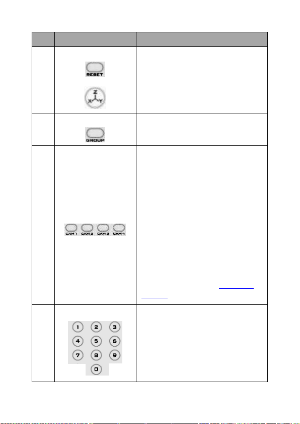
No
Item
Description
1
Reset
Press RESET or XYZ button to return
the camera lens to the default zoom
position (Z:0000).
2
Group
Not Applicable
3
Camera Select
Select CAM1-CAM4 in a multicamera environment
Press Camera Select buttons to
select a camera from Camera 1 to
Camera 4 in a multi-camera
environment.
However before using the Camera
Select function, first assign an ID
number (CAM 1 – CAM 4) to the
camera intended for remote control
operation by adjusting the DIP
switch located at the rear of the
camera. Please refer to DIP Switch
Settings section for details.
4
Preset Setting
Not Applicable
Page 16
16
5
Focus Setup
Manually focus camera lens on a
subject
Press either (F) FAR button or (N)
NEAR button to manually focus the
camera lens onto the subject.
Before using manual focus, make
sure Auto Focus mode is turned off
by pressing the AUTO FOCUS
button.
6
Auto Focus Control
Automatically focus camera lens on
a subject
Press AUTO FOCUS button and
camera lens will be automatically
focused on the subject.
7
Gain Control
Adjust Brightness
Press GAIN+ button to increase the
brightness or GAIN- button to
decrease the brightness.
Press AUTO button to activate auto
Gain Control and press again to exit.
8
P/T Speed
Adjust Pan/ Tilt Speed
Not Applicable
Page 17
17
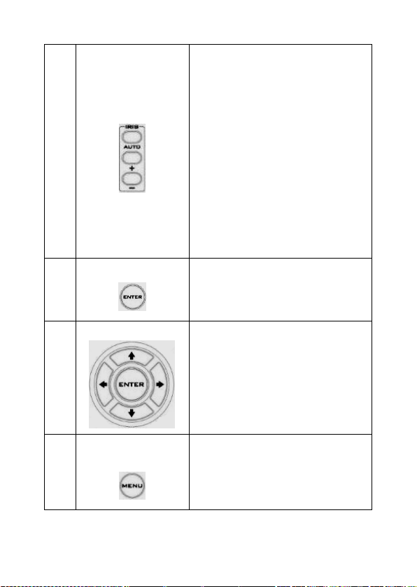
9
Iris Control
Make the subject appear brighter
Adjust the iris opening (aperture), to
control the amount of light coming
through the lens (i.e. the
"exposure"). Press IRIS+ button to
enlarge the iris opening to allow
more light to come in so that the
subject appears brighter and press
IRIS- button to shrink the iris
opening to allow less light to come
in so that the subject appears less
bright.
Press AUTO button activate auto Iris
Control and press again to exit.
10
ENTER
ENTER
Press ENTER key to select a
particular menu option or confirm a
parameter value.
11
Direction Arrows
Browse Menu Options
Press UP, DOWN, LEFT and RIGHT
arrow buttons to browse the menu
options or adjust parameter values.
12
Enter/ Exit Camera
Menu
Press the MENU button to Enter or
Exit the Camera OSD Menu
Page 18
18
13
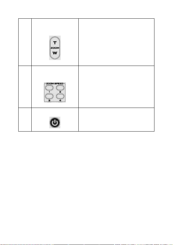
Zoom In/Out
Buttons
Zoom
Press either (T) TELE button to zoom
in on the subject such that it
appears to be close to the camera or
(W) WIDE button to zoom out from
the subject such that it appears to
be far away from the camera.
14
Zoom Speed Buttons
(4 speed selection)
Adjust Zoom In/Out Speed
Press the ZOOM SPEED buttons to
switch to different zoom speeds (4
being the highest and 1 being the
lowest).
15
Power Button
Switch ON/OFF camera
Page 19

19
5. OSD Menu Options
On-Screen Menu allows the user to change various camera settings
such as shooting conditions and the system setup. Press Menu button
on the IR remote control to enter the on-screen menu as shown below.
Main Menu
1. Camera Set
(Normal)
White Balance
Color temperature adjustment to make the
image look more natural.
IRIS
This is an adjustable aperture used to control
the amount of light coming through the lens.
The more the iris is opened, the more light it
lets in and the brighter the scene will be.
AGC
The setting that automatically adjusts the
amplification of the signal from the camera
sensor.
DNR
Digital Noise Reduction digitally removes any
noise found in each image, resulting in a
clearer image.
2. Video Output
Selection Way
This option configures how you can select the
video mode.
Enabling DIP SW 8 allows you to use the DIP
[MAIN MENU]
1: Camera Set (Normal)
2: Video Output
3: Remote Control
4: System
5: Camera Set (Advance)
6: Escape
Page 20

20
switch to set the video mode instead of the
remote control.
Pattern
Pattern generates color bars for color
calibration.
3. Remote Control
Remote control settings
4. System
System configuration
5. Camera Set
(Advance)
Fog Correction
When the surrounding area of the subject is
foggy and of a low contrast, turning on fog
correction will make the subject appear
clearer.
Aperture
Aperture adjusts the image sharpness.
Increasing the aperture setting so that the
foreground and background of your images
appear sharp.
Vivid Effect
Vivid effect adjusts the color saturation which
is basically the intensity of color in an image.
Pedestal Effect
The pedestal effect enables exposure
compensation which will engage the iris or
auto gain control depending on the shooting
situation. For best results we recommend
setting the pedestal effect to 4 or 5. The
pedestal effect allows the camera to brighten
up the image captured as you zoom in.
Backlight Correction
Use this function when the background is
brighter than the subject.
6. Escape
Exits the MENU
Page 21

21
Main
Options
Camera
Set
(Normal)
Video
Output
Remote
Control
System
Camera Set
(Advance)
Escape
Sub-Options
1. Camera
Name
1. Selection
Way
1. Remote
Source
1. Display
1. Camera
Name
2. Mirror
2. Video
Mode
2. Set RS422
2. Tally
Light
2. Mirror
3. White
Balance
3. Pattern
3. Set DVIP
3. Reset
All
3. White
Balance
4. Focus
4. Escape
4. Set IR
4. Update
Software
4. Focus
5. Iris 5. Escape
5. Escape
5. Iris
6. AGC 6. AGC
7. Escape
7. Fog
Correction
8. Aperture
9. Vivid Effect
10. Pedestal
Effect
11. Backlight
Correction
12. Day/Night
Mode
13. Shutter
14. Gamma
Mode
15. WD Mode
16. HR Mode
17. Contrast
18. Escape
Page 22

22
First Level
Main Options
Second Level
Sub-Options
Third Level
Parameters
Fourth Level
Parameters
Sub-Option
Descriptions
1. Camera Set
(Normal)
1. Camera
Name
NAME
DISPLAY SW
ON/OFF
POSITION
LOWER LEFT
UPPER LEFT
LOWER RIGHT
UPPER RIGHT
ESCAPE
2. Mirror
H+V V
H
OFF
3. White
Balance
MODE
AWB(AUTO)
AWC (ONE PUSH)
MWB (MANUAL)
3200K (INDOOR)
5600K
(OUTDOOR)
4200K (FLUO)
SMART ATW
OFF SMART1/2/3
MWB RED
COMPONENT
0~128~255
(Enabled when
MODE is set to
MWB
(MANUAL))
MWB BLUE
COMPONENT
0~128~255
(Enabled when
MODE is set to
MWB
(MANUAL))
ESCAPE
4. Focus
FOCUS MODE
AUTO MANUAL
AF SENSITIVITY
LOW
NORMAL
FOCUS SPEED
1~8
ESCAPE
5. Iris
IRIS MODE
AUTO IRIS
MANUAL
MANUAL IRIS
LEVEL
F1.6 F2.0 F2.4 F2.8
Page 23

23
F3.4 F4 F4.8 F5.6
F6.8
F8 F9.6 F11 F14
CLOSE
ESCAPE
6. AGC
DAY (COLOR)
AGC
AGC MODE
OFF
ON
MANUAL GAIN
0 dB ~ GAIN
LIMIT
GAIN LIMIT
9 dB
12 dB
15 dB
18 dB
21 dB
24 dB
27 dB
30 dB
33 dB
36 dB
39 dB
ESCAPE
DNR
DNR (AT AGC
ON)
ON
OFF
DNR LEVEL
0 1 2 3 4
5
ESCAPE
ESCAPE
7. Escape
2. Video
Output
1. Selection
Way
BY MENU
BY SWITCH
2. Video Mode
1080i60
1080i50
720p60
720p50
Page 24

24
1080p30
1080p25
1080p60
1080p50
3. Pattern
OFF
COLOR BAR
4. Escape
3. Remote
Control
1. Remote
Source
RS-422, SW
(Configurable
using DIP switch
bit 4 ONLY)
DVIP, SW
2. Set RS-422
CAMERA ID
MODE
BY MENU
BY SWITCH
CAMERA ID
1~7
RS-422 BAUD
RATE
9600 19200 38400 115200 ESCAPE
3. Set DVIP
DVIP BAUD
RATE
9600 19200 38400 57600 115200 ESCAPE
4. Set IR
IR GROUP ID
CAM1~4
(Configurable
using DIP
switch bit 9/10
ONLY)
ESCAPE
5. Escape
4. System
1. Display
ZOOM OSD
ZOOM OSD
ON/OFF
ESCAPE
DEBUG OSD
DEBUG IR OSD
ON/OFF
DEBUG CAM.
OSD
ON/OFF
DEBUG RS-422
OSD
ON/OFF
DEBUG DVIP OSD
ON/OFF
DEBUG REG OSD
ON/OFF
DEBUG FRAME
NO
ON/OFF
PWR ON CAM
TEST
ON/OFF
Page 25

25
DUAL LVDS TEST
ON/OFF
INT. COLOR BAR
ON/OFF
ESCAPE
Escape
2. Tally Light
RED/GREEN
GREEN
RED
OFF
3. Reset All
YES/NO
4. Update
Software
SW VERSION
ESCAPE
MB CPU
V00.31b
MB FPGA
V006
UPDATE ALL
YES/NO
ESCAPE
5. Escape
5. Camera Set
(ADVANCE)
1. Camera
Name
NAME
DISPLAY SW
ON/OFF
POSITION
UPPER LEFT
LOWER RIGHT
UPPER RIGHT
LOWER LEFT
ESCAPE
2. Mirror
H+V V H
OFF
3. White
Balance
MODE
AWB (AUTO)
AWC (ONE PUSH)
MWB (MANUAL)
3200K (INDOOR)
5600K
(OUTDOOR)
4200K (FLUO)
SMART ATW
(Enabled in
AWB (AUTO)
mode)
OFF
SMART1~3
MWB RED
COMPONENT
(Enabled in
MWB (Manual)
mode)
0~128~255
MWB BLUE
COMPONENT
0~128~255
Page 26

26
(Enabled in
MWB (Manual)
mode)
ESCAPE
4. Focus
FOCUS MODE
AUTO MANUAL
AF SENSITIVITY
LOW NORMAL
FOCUS SPEED
1 2 3 4 5 6 7 8
ESCAPE
5. Iris
IRIS MODE
AUTO
MANUAL
Manual IRIS
LEVEL
F1.6 F2.0 F2.4 F2.8
F3.4
F4 F4.8 F5.6 F6.8
F8 F9.6
F11
F14
CLOSE
ESCAPE
6. AGC
DAY (COLOR)
AGC
AGC MODE
ON/OFF
MANUAL GAIN
0dB~GAIN
LIMIT
GAIN LIMIT
9 dB
12 dB
15 dB
18 dB
21 dB
24 dB
Page 27

27
27 dB
30 dB
33 dB
36 dB
39 dB
ESCAPE
DNR
DNR(AT AGC ON)
ON
OFF
DNR LEVEL
0 1 2 3 4
5
ESCAPE
7. Fog
Correction
FOG
CORRECTION
OFF/ON
ESCAPE
8. Aperture
0~15
9. Vivid Effect
0~14
10. Pedestal
Effect
0~14
11. Backlight
Correction
OFF/ON
(This option is
enabled after
AGC is turned
on)
12. Day/Night
Mode
B/W
COLOR
13. Shutter
SHUTTER
SPEED
1/30
NORMAL
1/90
1/100 1/125 1/180 1/250
1/350
1/500 1/725 1/1000 1/1500
ESCAPE
Page 28

28
14. Gamma
Mode
STANDARD
MODE1 (WD
OFF)
MODE2 (WD
OFF)
MODE3 (WD
OFF)
MODE4 (WD
OFF)
15. WD Mode
VE/ON/OFF
(This option is
enabled after
AGC is turned
on) 16. HR Mode
ON/OFF
17. Contrast
0-31
Default is 16
18. Escape
6. Escape
Page 29

29
6. DIP Switch Settings
DIP SW 1/2/3
VISCA ID
ON / OFF / OFF
VISCA-ID 1
OFF / ON / OFF
VISCA-ID 2
ON / ON / OFF
VISCA-ID 3
OFF / OFF / ON
VISCA-ID 4
ON / OFF / ON
VISCA-ID 5
OFF / ON / ON
VISCA-ID 6
ON / ON / ON
VISCA-ID 7
DIP SW 4
Remote Control Protocol
ON
DVIP
OFF
RS-422
DIP SW 5/6/7
Resolution
OFF / OFF / OFF
1920x1080i60
ON / OFF / OFF
1920x1080i50
OFF / ON / OFF
1280x720p60
ON / ON / OFF
1280x720p50
OFF / OFF / ON
1920x1080p30
ON / OFF / ON
1920x1080p25
OFF / ON / ON
1920x1080p60
ON / ON / ON
1920x1080p50
DIP SW 8
Video Mode Selection Method
ON
ON = video mode selectable by DIP switch only
OFF
OFF = video mode selectable by menu
DIP SW 9/10
Camera Select Function (IR Remote Control) –
Camera ID Assignment
OFF / OFF
CAM 1
ON / OFF
CAM 2
OFF / ON
CAM 3
ON / ON
CAM 4
Page 30

30
7. RS-422 Control Protocol
7.1 PIN Descriptions
Controller
BC-80 Camera
GND 1 White/Orange
White/Orange
1
GND
NC 2 Orange
Orange 2 NC
TX- 3 White/Green
White/Green
3
RX-
RX- 4 Blue
Blue 4 TX-
RX+ 5 White/Blue
White/Blue
5
TX+
TX+ 6 Green
Green 6 RX+
NC 7 White/Brown
White/Brown
7
NC
NC 8 Brown
Brown 8 NC
7.2 Control Operation Guide
7.2.1 Overview of VISCA
In VISCA, the side outputting commands, for example a computer, is
called the controller, while the side receiving the commands, such as
the BC-80, is called the peripheral device. The BC-80 serves as a
peripheral device in VISCA. In VISCA, up to seven peripheral devices
like the BRC-300/P can be connected to one controller using
communication conforming to the RS-232C/RS-422 standard. The
parameters of RS-232C/RS-422 are as follows.
GND
Page 31

31
• Communication speed: 38400 bps
• Data bits: 8
• Start bit: 1
• Stop bit: 1
• Non parity
Flow control using XON/XOFF and RTS/CTS, etc., is not supported.
The address of the controller is fixed at 0.
The addresses of peripheral devices are described as follows.
When the address of the controller is fixed at 0
The addresses of the peripheral devices are 1, 2, 3… in order, starting
from the one nearest the controller. The address of the peripheral
device is set by sending address commands during the initialization of
the network.
When the address of the controller is fixed at 1 through 7
The addresses of the peripheral devices will be set on a pre-selected
number. Within a single system, the same number can be used only
once. If an address-switch number other than 0 is to be used, change
the BC-80 address switch to a different number beforehand.
Each VISCA device has a VISCA IN and VISCA OUT connector.
Set the DTR input (the S output of the controller) of VISCA IN to H
when controlling VISCA equipment from the controller.
Fig. 1 VISCA network configuration
Page 32

32
7.2.2 VISCA Communication Specifications
VISCA Packet Structure
The basic unit of VISCA communication is called a packet (Fig. 2). The
first byte of the packet is called the header and comprises the sender’s
and receiver’s addresses. For example, the header of the packet sent
to the BC-80 assigned address 1 from the controller (address 0) is
hexadecimal 81H. The packet sent to the BC-80 assigned address 2 is
82H. In the command list, as the header is 8X, input the address of the
BC-80 at X. The header of the reply packet from the BC-80 assigned
address 1 is 90H. The packet from the BC-80 assigned address 2 is A0H.
Some of the commands for setting BC-80 units can be sent to all
devices at one time (broadcast). In the case of broadcast, the header
should be hexadecimal 88H.
When the terminator is FFH, it signifies the end of the packet.
Fig. 2 Packet structure
Note
Fig. 2 shows the packet structure, while Fig. 3 shows the actual
waveform. Data flow will take place with the LSB first.
Page 33

33
Fig. 3 Actual waveform for 1 byte
Timing Chart
As VISCA Command processing can only be carried out one time in a
Vertical cycle, it takes the maximum 1V cycle time for an
ACK/Completion to be returned. If the Command ACK/Completion
communication time can be cut shorter than the 1V cycle time, then
every 1V cycle can receive a Command.
From this point, if 2 or more commands in a row are to be sent, wait
for the first command (for normal commands, an ACK or an error
Page 34

34
message, for query commands, an Inquiry Packet) to be carried out
before sending the next one.
Command and inquiry
• Command
Sends operational commands to the BC-80.
• Inquiry
Used for inquiring about the current state of the BC-80.
Command Packet
Note
Inquiry
8X QQ RR … FF
QQ1) = Command/Inquiry
RR2) = category code
1)
QQ = 01 (Command), 09 (Inquiry)
2)
RR = 00 (Interface), 04 (camera 1), 06 (Pan/Tilter)
X = 1 to 7: BC-80 address
Responses for commands and inquiries
• ACK message
Returned by the BC-80 when it receives a command. No ACK message
is returned for inquiries.
• Completion message
Returned by the BC-80 when execution of commands or inquiries is
completed. In the case of inquiry commands, it will contain reply data
for the inquiry after the 3rd byte of the packet. If the ACK message is
omitted, the socket number will contain a 0.
Reply Packet
Note
Ack
X0 4Y FF
Y = socket number
Completion (Commands)
X0 5Y FF
Y = socket number
Completion (Inquiries)
X0 5Y … FF
Y = socket number
X = 9 to F: BC-80 address + 8
• Error message
When a command or inquiry command could not be executed or failed,
an error message is returned.
Page 35

35
Error Packet
Description
X0 6Y 01 FF
Message length error
X0 6Y 02 FF
Syntax error
X0 6Y 03 FF
Command buffer full
X0 6Y 04 FF
Command cancelled
X0 6Y 05 FF
No socket (to be cancelled)
X0 6Y 41 FF
Command not executable
X = 9 to F: BC-80 address + 8, Y = socket number
Socket number = 1 (normal)
Socket number
When command messages are sent to the BC-80, it is normal to send
the next command message after waiting for the completion message
or error message to return.
As the completion message or error message also has a socket number,
it indicates which command has ended.
The ACK message is not returned for these commands and inquiries,
and only the completion message of socket number 0 is returned.
7.2.3 VISCA Device Setting Command
Before starting control of the BC-80, be sure to send the Address
command and the IF_Clear command using the broadcast function.
VISCA interface command
• IF_Clear
Clears the command buffers in the BC-80 and cancels the command
currently being executed.
Command Packet
Reply Packet
Note
IF_Clear
8X 01 00 01 FF
X0 50 FF
IF_Clear
(broadcast)
88 01 00 01 FF
88 01 00 01 FF
Page 36

36
X = 1 to 7: BC-80 address (For inquiry packet)
X = 9 to F: BC-80 address + 8 (For reply packet)
7.2.4 VISCA Command/ACK Protocol
Command
Command
Message
Reply
Message
Comments
General
Command
81 01 04 38
02 FF
(Example)
90 41 FF
(ACK)+90 51
FF
(Completion)
90 42 FF
90 52 FF
Returns ACK when
a command has
been accepted, and
Completion when a
command has been
executed.
81 01 04 38
FF
(Example)
90 60 02 FF
(Syntax Error)
Accepted a
command which is
not supported or a
command lacking
parameters
81 01 04 38
02 FF
(Example)
90 60 03 FF
(Command
Buffer Full)
There are two
commands
currently being
executed, and the
command could
not be accepted.
81 01 04 08
02 FF
(Example)
90 61 41 FF
(Command
Not
Executable)
90 62 41 FF
Could not execute
the command in
the current mode.
Inquiry
Command
81 09 04 38
FF
(Example)
90 50 02 FF
(Completion)
ACK is not returned
for the inquiry
command.
81 09 05 38
FF
(Example)
90 60 02 FF
(Syntax Error)
Accepted an
incompatible
command.
Address
88 30 01 FF
88 30 02 FF
Returned the
Page 37

37
Set
device address to
+1.*
IF_Clear
(Broadcast)
88 01 00 01
FF
88 01 00 01 FF
Returned the same
command.
IF_Clear
(For x)
8x 01 00 01
FF
z0 50 FF
(Completion)
ACK is not returned
for this command.
*When the address-switch is fixed at 0, the value x in 88 30 0x FF will
be indeterminate.
Do not transmit the command (except Address Set, IF_Clear,
CAM_POWER), when menu panel shows on the screen. In that case,
clear the menu panel first using CAM_Menu Command, and then
proceed.
7.2.5 VISCA Camera-Issued Messages
ACK/Completion Messages
Command
Command
Message
Comments
ACK
z0 4y FF
(y: Socket No.)
Returned when the command
is accepted
Completion
z0 5y FF
(y: Socket No.)
Returned when the command
has been executed
z = Device address + 8
Error Messages
Command
Command
Messages
Comments
Syntax Error
z0 60 02 FF
Returned when the command
format is different or when a
command with illegal
command parameters is
accepted.
Command
Buffer Full
z0 60 03 FF
Indicates that two sockets are
already being used (executing
Page 38

38
two commands) and the
command could not be
accepted when received.
No Socket
z0 6y 05 FF
(y: Socket No.)
Returned when no command
is executed in a socket
specified by the cancel
command, or when an invalid
socket number is specified.
Command Not
Executable
z0 6y 41 FF
(y: Socket No.)
Returned when a command
cannot be executed due to
current conditions. For
example, when commands
controlling the focus
manually are received during
auto focus.
7.2.6 BC-80 Commands
BC-80 Command List
Command Set
Command
Command
Packet
Comments
AddressSet
Broadcast
88 30 01
FF
Address
Set
IF_Clear
Broadcast
88 01 00
01 FF
I/F Clear
CAM_Power
On
8x 01 04
00 02 FF
Power
On/Off
Off
8x 01 04
00 03 FF
CAM_ZOOM
Stop
8x 01 04
07 00 FF
Tele (Standard)
8x 01 04
07 02 FF
Wide (Standard)
8x 01 04
07 03 FF
Page 39

39
Tele (Variable)
8x 01 04
07 2p FF
p (=0: Slow
to 7:Fast)
Wide (Variable)
8x 01 04
07 3p FF
p (=0: Slow
to 7:Fast)
Direct
8x 01 04
47 0p 0q
0r 0s FF
pqrs: Zoom
Position*
CAM_Focus
Stop
8x 01 04
08 00 FF
Far (Standard)
8x 01 04
08 02 FF
Near (Standard)
8x 01 04
08 03 FF
Direct
8x 01 04
48 0p 0q
0r 0s FF
pqrs: Focus
Position*
Auto Focus
8x 01 04
38 02 FF
AF ON/OFF
Manual Focus
8x 01 04
38 03 FF
One Push
Trigger
8x 01 04
18 01 FF
One Push
AF Trigger
CAM_WB
Auto
8x 01 04
35 00 FF
Normal
Auto
Indoor
8x 01 04
35 01 FF
Indoor
Mode
Outdoor
8x 01 04
35 02 FF
Outdoor
Mode
One Push WB
8x 01 04
35 03 FF
One Push
WB Mode
Manual
8x 01 04
35 05 FF
Manual
Control
Mode
One Push
Trigger
8x 01 04
10 05 FF
One Push
WB Trigger
Page 40

40
CAM_RGain
Reset
8x 01 04
03 00 FF
Default R
Gain
setting
Up
8x 01 04
03 02 FF
Down
8x 01 04
03 03 FF
Direct
8x 01 04
43 00 00
0p 0q FF
R Gain
Direct pq
(=00 to FF)
CAM_BGain
Reset
8x 01 04
04 00 FF
Default B
Gain
setting
Up
8x 01 04
04 02 FF
Down
8x 01 04
04 03 FF
Direct
8x 01 04
44 00 00
0p 0q FF
B Gain
Direct pq
(=00 to FF)
CAM_AE
Full Auto
8x 01 04
39 00 FF
Automatic
exposure
mode
Manual
8x 01 04
39 03 FF
Manual
control
mode
Shutter Priority
8x 01 04
39 0A FF
Shutter
priority
automatic
exposure
mode
Iris Priority
8x 01 04
39 0B FF
Iris priority
automatic
exposure
mode
Page 41

41
Bright
8x 01 04
39 0D FF
Bright
mode
(Manual)
CAM_Shutter
Reset
8x 01 04
0A 00 FF
Default
Shutter
setting
Up
8x 01 04
0A 02 FF
Down
8x 01 04
0A 03 FF
CAM_Iris
Reset
8x 01 04
0B 00 FF
Default Iris
Setting
Up
8x 01 04
0B 02 FF
Down
8x 01 04
0B 03 FF
Direct
8x 01 04
4B 00 00
0p 0q FF
pq: Iris
Position*
CAM_Gain
Reset
8x 01 04
0C 00 FF
Default
Gain
setting
Up
8x 01 04
0C 02 FF
Down
8x 01 04
0C 03 FF
Direct
8x 01 04
4C 00 00
0p 0q FF
pq: Iris
Position*
CAM_Backlight
On
8x 01 04
33 02 FF
Back Light
ON/OFF
Off
8x 01 04
33 03 FF
PTZ_Position
Reset
8x 01 04
3F 00 0p
Memory
Number p
Page 42

42
FF
(=0 to 50)
Set
8x 01 04
3F 01 0p
FF
Memory
Number p
(=0 to 50)
Recall
8x 01 04
3F 02 0p
FF
Memory
Number p
(=0 to 50)
CAM_Menu
On
8x 01 06
06 02 FF
Menu ON
Off
8x 01 06
06 03 FF
Menu OFF
Pan-tilt Drive
Up
8x 01 06
01 VV WW
03 01 FF
PanSpeed
VV
(=01:Slow
to
18h:Fast)
TiltSpeed
WW
(=01:Slow
to
18h:Fast)
Down
8x 01 06
01 VV WW
03 02 FF
Left
8x 01 06
01 VV WW
01 03 FF
Right
8x 01 06
01 VV WW
02 03 FF
UpLeft
8x 01 06
01 VV WW
01 01 FF
UpRight
8x 01 06
01 VV WW
02 01 FF
DownLeft
8x 01 06
01 VV WW
01 02 FF
DownRight
8x 01 06
01 VV WW
02 02 FF
Page 43

43
Stop
8x 01 06
01 VV WW
03 03 FF
AbsolutePosition
8x 01 06
02 VV 00
0Y 0Y 0Y
0Y 0Y 0Z
0Z 0Z 0Z
FF
Speed VV
(=01: Slow
to
18h:Fast)
YYYYY: Pan
Position*
ZZZZ: Tilt
Position*
RelativePosition
8x 01 06
03 VV 00
0Y 0Y 0Y
0Y 0Y 0Z
0Z 0Z 0Z
FF
Speed VV
(=01: Slow
to
18h:Fast)
YYYYY: Pan
Position*
ZZZZ: Tilt
Position*
Home
8x 01 06
04 FF
Reset
8x 01 06
05 FF
CAM_ImgFlip
On
8x 01 04
66 02 FF
Off
8x 01 04
66 03 FF
Cam_PanReverse
On
8x 01 7E
01 06 00
01 FF
Off
8x 01 7E
01 06 00
00 FF
Cam_TiltReverse
On
8x 01 7E
01 09 00
Page 44

44
01 FF
Off
8x 01 7E
01 09 00
00 FF
Cmd_Tally
On
8x 01 7E
01 0A 00
02 FF
When
Power is
on, return
to off.
Off
8x 01 7E
01 0A 00
03 FF
Cmd_PT_M_Speed
Preset PT Speed
8x 01 7E
01 0B 0p
0q FF
p: Memory
number
(=0 to 50)
q: Speed
(=1 to
18:fast)
*See the section under VISCA Command Setting Values
BC-80 Inquiry Command List
Inquiry Command
Command
Packet
Inquiry
Packet
Comments
CAM_PowerInq
8x 09 04 00 FF
y0 50 02
FF
On
y0 50 03
FF
Off
(Standby)
CAM_ZoomPosInq
8x 09 04 47 FF
y0 50 0p
0q 0r 0s
FF
pqrs: Zoom
Position
CAM_FocusModeI
nq
8x 09 04 38 FF
y0 50 02
FF
Auto Focus
y0 50 03
FF
Manual
Focus
CAM_FocusPosInq
8x 09 04 48 FF
y0 50 0p
pqrs: Focus
Page 45

45
0q 0r 0s
FF
Position
CAM_WBModeInq
8x 09 04 35 FF
y0 50 00
FF
Auto
y0 50 01
FF
Indoor
y0 50 02
FF
Outdoor
y0 50 03
FF
One Push
WB
y0 50 05
FF
Manual
CAM_RGainInq
8x 09 04 43 FF
y0 50 00
00 0p 0q
FF
pq: R Gain
CAM_BGainInq
8x 09 04 44 FF
y0 50 00
00 0p 0q
FF
pq: B Gain
CAM_AEModeInq
8x 09 04 39 FF
y0 50 00
FF
Full Auto
y0 50 03
FF
Manual
y0 50 0A
FF
Shutter
Priority
y0 50 0B
FF
Iris Priority
CAM_ShutterPosI
nq
8x 09 04 4A FF
y0 50 00
00 0p 0q
FF
pq: Shutter
Position
CAM_IrisPosInq
8x 09 04 4B FF
y0 50 00
00 0p 0q
FF
pq: Iris
Position
CAM_GainPosInq
8x 09 04 4C FF
y0 50 00
00 0p 0q
FF
pq: Gain
Position
Page 46

46
CAM_BackLightM
odeInq
8x 09 04 33 FF
y0 50 02
FF
On
y0 50 03
FF
Off
CAM_MemoryInq
8x 09 04 3F FF
y0 50 pp
FF
pp:
Memory
number for
PTZ last
operated*
CAM_MENUInq
8x 09 06 06 FF
y0 50 02
FF
On
y0 50 03
FF
Off
CAM_VersionInq
8x 09 00 02 FF
y0 50 00
01
mn pq rs
tu vw FF
mnpq:
Model
Code
(04xx)
rstu: ROM
version
vw: Socket
Number
(02)
CAM_ImgFlipInq
8x 09 04 66 FF
y0 50 02
FF
On
y0 50 03
FF
Off
CAM_PanReverseI
nq
8x 09 7E 01 06 FF
y0 50 01
FF
On
y0 50 00
FF
Off
CAM_TiltReverseI
nq
8x 09 7E 01 09 FF
y0 50 01
FF
On
y0 50 00
FF
Off
PanTilt_Status
8x 09 06 10 FF
y0 50 pq
pqrs:
Page 47

47
rs FF
PanTilt
Status
PanTilt_Max_Spee
d
8x 09 06 11 FF
y0 50 pq
rs FF
pq: Pan
Max Speed,
rs: Tilt Max
Speed
PanTilt_Position
8x 09 06 12 FF
y0 50 0p
0q 0r 0s 0t
0u 0v 0w
0x FF
pqrst: Pan
Position
uvwx: Tilt
Position
Tally
8x 09 7E 01 0A
FF
y0 50 02
FF
On
y0 50 03
FF
Off
PanTilt_Memory_
Speed
8x 09 7E 01 0B
0p FF
y0 50 0q
FF
p: Preset
No. 0 - 50,
qq: Speed 1
- 18 (h)
*See the section under VISCA Command Setting Values
Page 48

48
8. DVIP Control Operation Guide
8.1 Physical Layer
• Control Interface: Ethernet
• Communication Speed: 10/100Mbps
• Control Protocol: TCP/IP
8.2 General Connection Information
• By default, the DVIP is configured to operate in DHCP mode. User
is allowed to re- configure to static IP address.
• TCP/IP Control port numbers
TCP port: 5002
UDP port: 5002
8.3 Packet Data
Control Command Packet (TCP)
Byte (8 bits)
Descriptions
0
Packet Length High Byte
1
Packet Length Low Byte
2
Command_Data [0]
…
…
513
Command_Data [511]
Broadcast Packet
Byte (8 bits)
Descriptions
0
Packet Length High Byte
1
Packet Length Low Byte
2
0x80
3
Command
4
Parameter 1
…
…
251
Parameter 248
Page 49

49
Broadcast Command List – Request TCP/IP information
Command Issue to DVIP device
Request TCP/IP information, include DHCP mode, DHCP Host name,
IP address, Netmask, MAC address, Gateway, Primary DNS,
Secondary DNS
Command
0x00
Parameter 1
0x45
Parameter 2
0x54
Parameter 3
0x48
Parameter 4
0x5F
Parameter 5
0x52
Parameter 6
0x45
Parameter 7
0x51
Command Return from DVIP device
Length
Descriptions
1 Byte
Data Length High Byte
1 Byte
Data Length Low Byte
1 Byte
0x80
1 Byte
0x00
1 Byte
DHCP; 0: Disable; 1: Enable
16 Bytes
DHCP Host name (15 bytes max) + Null (0x00)
terminated
6 Bytes
MAC Address
4 Bytes
IP Address
4 Bytes
Netmask
4 Bytes
Gateway
4 Bytes
Primary DNS address
4 Bytes
Secondary DNS address
Page 50

50
Broadcast Command List – Request specific DVIP device firmware
revision
Command Issue to DVIP device
Request DVIP Firmware Revision
Command
0x01
Parameter 1
DVIP MAC address [0]
Parameter 2
DVIP MAC address [1]
Parameter 3
DVIP MAC address [2]
Parameter 4
DVIP MAC address [3]
Parameter 5
DVIP MAC address [4]
Parameter 6
DVIP MAC address [5]
Parameter 7
0x46
Parameter 8
0x57
Parameter 9
0x56
Parameter 10
0x45
Parameter 11
0x52
Parameter 12
0x5F
Parameter 13
0x52
Parameter 14
0x45
Parameter 15
0x51
Command Return from DVIP device
Length
Descriptions
1 Byte
0x00 (Data Length High Byte)
1 Byte
0x06 (Data Length Low Byte)
1 Byte
0x80
1 Byte
0x01
1 Byte
Firmware Revision Major Number
1 Byte
Firmware Revision Minor Number
Page 51

51
Broadcast Command List – Set DHCP Mode
Command Issue to DVIP device
Set DHCP Mode
Command
0x02
Parameter 1
DVIP MAC address [0]
Parameter 2
DVIP MAC address [1]
Parameter 3
DVIP MAC address [2]
Parameter 4
DVIP MAC address [3]
Parameter 5
DVIP MAC address [4]
Parameter 6
DVIP MAC address [5]
Parameter 7
0x53
Parameter 8
0x45
Parameter 9
0x54
Parameter 10
0x5F
Parameter 11
0x44
Parameter 12
0x48
Parameter 13
0x43
Parameter 14
0x50
Parameter 15
0x4D
Parameter 16
0x4F
Parameter 17
0x44
Parameter 18
0x45
Parameter 19
0x00: Disable; 0x01: Enable
Command Return from DVIP device
Length
Descriptions
1 Byte
0x00 (Data Length High Byte)
1 Byte
0x06 (Data Length Low Byte)
1 Byte
0x80
1 Byte
0x02
1 Byte
0x06 (ACK) or 0x15 (NACK)
Page 52

52
Broadcast Command List – Set IP Address
Command Issue to DVIP device
Set IP Address
Command
0x03
Parameter 1
DVIP MAC address [0]
Parameter 2
DVIP MAC address [1]
Parameter 3
DVIP MAC address [2]
Parameter 4
DVIP MAC address [3]
Parameter 5
DVIP MAC address [4]
Parameter 6
DVIP MAC address [5]
Parameter 7
0x53
Parameter 8
0x45
Parameter 9
0x54
Parameter 10
0x5F
Parameter 11
0x49
Parameter 12
0x50
Parameter 13
0x41
Parameter 14
0x44
Parameter 15
0x52
Parameter 16
IP_Address [0]
Parameter 17
IP_Address [1]
Parameter 18
IP_Address [2]
Parameter 19
IP_Address [3]
Parameter 20
Gateway [0]
Parameter 21
Gateway [1]
Parameter 22
Gateway [2]
Parameter 23
Gateway [3]
Command Return from DVIP device
Length
Descriptions
1 Byte
0x00 (Data Length High Byte)
1 Byte
0x06 (Data Length Low Byte)
1 Byte
0x80
1 Byte
0x03
Page 53

53
1 Byte
0x06 (ACK) or 0x15 (NACK)
Broadcast Command List – Reset to Factory Default
Command Issue to DVIP device
Reset to Factory Default
Command
0x04
Parameter 1
DVIP MAC address [0]
Parameter 2
DVIP MAC address [1]
Parameter 3
DVIP MAC address [2]
Parameter 4
DVIP MAC address [3]
Parameter 5
DVIP MAC address [4]
Parameter 6
DVIP MAC address [5]
Parameter 7
0x52
Parameter 8
0x45
Parameter 9
0x53
Parameter 10
0x45
Parameter 11
0x54
Command Return from DVIP device
Length
Descriptions
1 Byte
0x00 (Data Length High Byte)
1 Byte
0x06 (Data Length Low Byte)
1 Byte
0x80
1 Byte
0x04
1 Byte
0x06 (ACK) or 0x15 (NACK)
Broadcast Command List – Get Device Model Number
Command Issue to DVIP device
Get Device Model Number
Command
0x05
Parameter 1
DVIP MAC address [0]
Parameter 2
DVIP MAC address [1]
Parameter 3
DVIP MAC address [2]
Parameter 4
DVIP MAC address [3]
Page 54

54
Parameter 5
DVIP MAC address [4]
Parameter 6
DVIP MAC address [5]
Parameter 7
0x47
Parameter 8
0x45
Parameter 9
0x54
Parameter 10
0x5F
Parameter 11
0x4D
Parameter 12
0x4F
Parameter 13
0x44
Parameter 14
0x45
Parameter 15
0x4C
Parameter 16
0x5F
Parameter 17
0x4E
Parameter 18
0x41
Parameter 19
0x4D
Parameter 20
0x45
Command Return from DVIP device
Length
Descriptions
1 Byte
0x00 (Data Length High Byte)
1 Byte
0x06 (Data Length Low Byte)
1 Byte
0x80
1 Byte
0x04
16 Bytes
Device Model Number is 16 Bytes maximum; use
null padding (0x00) if it is less than 16 bytes.
UDP Packet
Byte (8 bits)
Descriptions
0
Packet Length High Byte
1
Packet Length Low Byte
2
0x81
3
Command
4 … 251
Parameter 1 … Parameter 248
Page 55

55
UDP Command List – Request TCP/IP information
Command Issue to DVIP device
Request TCP/IP information, include DHCP mode, DHCP Host name,
IP address, Netmask, MAC address, Gateway, Primary DNS,
Secondary DNS
Command
0x00
Parameter 1
0x45
Parameter 2
0x54
Parameter 3
0x48
Parameter 4
0x5F
Parameter 5
0x52
Parameter 6
0x45
Parameter 7
0x51
Command Return from DVIP device
Length
Descriptions
1 Byte
Data Length High Byte
1 Byte
Data Length Low Byte
1 Byte
0x80
1 Byte
0x00
1 Byte
DHCP; 0: Disable; 1: Enable
16 Bytes
DHCP Host name (15 bytes max) + Null (0x00)
terminated
6 Bytes
MAC Address
4 Bytes
IP Address
4 Bytes
Netmask
4 Bytes
Gateway
4 Bytes
Primary DNS address
4 Bytes
Secondary DNS address
UDP Command List – Request specific DVIP device firmware revision
Command Issue to DVIP device
Request DVIP Firmware Revision
Command
0x01
Page 56

56
Parameter 1
0x46
Parameter 2
0x57
Parameter 3
0x56
Parameter 4
0x45
Parameter 5
0x52
Parameter 6
0x5F
Parameter 7
0x52
Parameter 8
0x45
Parameter 9
0x51
Command Return from DVIP device
Length
Descriptions
1 Byte
0x00 (Data Length High Byte)
1 Byte
0x06 (Data Length Low Byte)
1 Byte
0x80
1 Byte
0x01
1 Byte
Firmware Revision Major Number
1 Byte
Firmware Revision Minor Number
UDP Command List – Set DHCP Mode
Command Issue to DVIP device
Set DHCP Mode
Command
0x02
Parameter 1
0x53
Parameter 2
0x45
Parameter 3
0x54
Parameter 4
0x5F
Parameter 5
0x44
Parameter 6
0x48
Parameter 7
0x43
Parameter 8
0x50
Parameter 9
0x4D
Parameter 10
0x4F
Parameter 11
0x44
Page 57

57
Parameter 12
0x45
Parameter 13
0x00: Disable; 0x01: Enable
Command Return from DVIP device
Length
Descriptions
1 Byte
0x00 (Data Length High Byte)
1 Byte
0x06 (Data Length Low Byte)
1 Byte
0x81
1 Byte
0x02
1 Byte
0x06 (ACK) or 0x15 (NACK)
UDP Command List – Set IP Address & Gateway Address
Command Issue to DVIP device
Set IP Address
Command
0x03
Parameter 1
0x53
Parameter 2
0x45
Parameter 3
0x54
Parameter 4
0x5F
Parameter 5
0x49
Parameter 6
0x50
Parameter 7
0x41
Parameter 8
0x44
Parameter 9
0x52
Parameter 10
IP_Address [0]
Parameter 11
IP_Address [1]
Parameter 12
IP_Address [2]
Parameter 13
IP_Address [3]
Parameter 14
Gateway [0]
Parameter 15
Gateway [1]
Parameter 16
Gateway [2]
Parameter 17
Gateway [3]
Page 58

58
Command Return from DVIP device
Length
Descriptions
1 Byte
0x00 (Data Length High Byte)
1 Byte
0x05 (Data Length Low Byte)
1 Byte
0x81
1 Byte
0x03
1 Byte
0x06 (ACK) or 0x15 (NACK)
UDP Command List – Reset to Factory Default
Command Issue to DVIP device
Reset to Factory Default
Command
0x04
Parameter 1
0x52
Parameter 2
0x45
Parameter 3
0x53
Parameter 4
0x45
Parameter 5
0x54
Command Return from DVIP device
Length
Descriptions
1 Byte
0x00 (Data Length High Byte)
1 Byte
0x06 (Data Length Low Byte)
1 Byte
0x81
1 Byte
0x04
1 Byte
0x06 (ACK) or 0x15 (NACK)
UDP Command List – Set DHCP Host Name
Command Issue to DVIP device
Set DHCP Host Name
Command
0x09
Parameter 1
0x53
Parameter 2
0x45
Parameter 3
0x54
Parameter 4
0x5F
Page 59

59
Parameter 5
0x44
Parameter 6
0x48
Parameter 7
0x43
Parameter 8
0x50
Parameter 9
0x4E
Parameter 10
0x41
Parameter 11
0x4D
Parameter 12
0x45
Parameter
13…
Name (ASCII), 15 bytes Max.
Parameter
Null (0x00) terminated
Command Return from DVIP device
Length
Descriptions
1 Byte
0x00 (Data Length High Byte)
1 Byte
0x05 (Data Length Low Byte)
1 Byte
0x81
1 Byte
0x09
1 Byte
0x06 (ACK) or 0x15 (NACK)
UDP Command List – Set Netmask
Command Issue to DVIP device
Set Netmask
Command
0x0B
Parameter 1
0x53
Parameter 2
0x45
Parameter 3
0x54
Parameter 4
0x5F
Parameter 5
0x4E
Parameter 6
0x45
Parameter 7
0x54
Parameter 8
0x4D
Parameter 9
0x41
Parameter 10
0x53
Page 60

60
Parameter 11
0x4B
Parameter 12
Net_Mask [0]
Parameter 13
Net_Mask [1]
Parameter 14
Net_Mask [2]
Parameter 15
Net_Mask [3]
Command Return from DVIP device
Length
Descriptions
1 Byte
0x00 (Data Length High Byte)
1 Byte
0x05 (Data Length Low Byte)
1 Byte
0x81
1 Byte
0x0B
1 Byte
0x06 (ACK) or 0x15 (NACK)
UDP Command List – Set Gateway Address
Command Issue to DVIP device
Set Gateway Address
Command
0x0C
Parameter 1
0x53
Parameter 2
0x45
Parameter 3
0x54
Parameter 4
0x5F
Parameter 5
0x47
Parameter 6
0x41
Parameter 7
0x54
Parameter 8
0x45
Parameter 9
0x57
Parameter 10
0x41
Parameter 11
0x59
Parameter 12
Gateway [0]
Parameter 13
Gateway [1]
Parameter 14
Gateway [2]
Parameter 15
Gateway [3]
Page 61

61
Command Return from DVIP device
Length
Descriptions
1 Byte
0x00 (Data Length High Byte)
1 Byte
0x05 (Data Length Low Byte)
1 Byte
0x81
1 Byte
0x0C
1 Byte
0x06 (ACK) or 0x15 (NACK)
UDP Command List – Set Primary DNS Address
Command Issue to DVIP device
Set Gateway Address
Command
0x0D
Parameter 1
0x53
Parameter 2
0x45
Parameter 3
0x54
Parameter 4
0x5F
Parameter 5
0x50
Parameter 6
0x52
Parameter 7
0x49
Parameter 8
0x44
Parameter 9
0x4E
Parameter 10
0x53
Parameter 11
Primary_DNS_IP [0]
Parameter 12
Primary_DNS_IP [1]
Parameter 13
Primary_DNS_IP [2]
Parameter 14
Primary_DNS_IP [3]
Command Return from DVIP device
Length
Descriptions
1 Byte
0x00 (Data Length High Byte)
1 Byte
0x05 (Data Length Low Byte)
1 Byte
0x81
1 Byte
0x0D
1 Byte
0x06 (ACK) or 0x15 (NACK)
Page 62

62
UDP Command List – Set Secondary DNS Address
Command Issue to DVIP device
Set Gateway Address
Command
0x0E
Parameter 1
0x53
Parameter 2
0x45
Parameter 3
0x54
Parameter 4
0x5F
Parameter 5
0x53
Parameter 6
0x45
Parameter 7
0x43
Parameter 8
0x44
Parameter 9
0x4E
Parameter 10
0x53
Parameter 11
Secondary_DNS_IP [0]
Parameter 12
Secondary _DNS_IP [1]
Parameter 13
Secondary _DNS_IP [2]
Parameter 14
Secondary _DNS_IP [3]
Command Return from DVIP device
Length
Descriptions
1 Byte
0x00 (Data Length High Byte)
1 Byte
0x05 (Data Length Low Byte)
1 Byte
0x81
1 Byte
0x0E
1 Byte
0x06 (ACK) or 0x15 (NACK)
UDP Command List – Initial DVIP Configuration
Command Issue to DVIP device
Initial DVIP Configuration
Command
0x0F
Parameter 1
0x49
Parameter 2
0x4E
Page 63

63
Parameter 3
0x49
Parameter 4
0x54
Parameter 5
0x5F
Parameter 6
0x45
Parameter 7
0x32
Parameter 8
0x50
Parameter 9
DHCP_Mode
Parameter 10
DHCP_Host_Name [0-14] (ASCII), 15 Bytes Max.
Parameter N
Null (0x00)
Parameter N+1
MAC_Address [0-3]
Parameter N+5
IP_Address [0-3]
Parameter N+9
Gateway_IP [0-3]
Parameter N+13
Net_Mask [0-3]
Parameter N+17
Primary_DNS_IP [0-3]
Parameter N+21
Secondary_DNS_IP [0-3]
Command Return from DVIP device
Length
Descriptions
1 Byte
0x00 (Data Length High Byte)
1 Byte
0x05 (Data Length Low Byte)
1 Byte
0x81
1 Byte
0x0F
1 Byte
0x06 (ACK) or 0x15 (NACK)
Page 64

64
9. Firmware Upgrade
1) Copy MB CPU and MB FPGA image files into the root directory of
a USB hard drive (<16 GB) and insert it into the USB Upgrade port
(You may use a USB extension cord).
2) Open the OSD menu using IR remote control by pressing the
MENU button.
3) Browse to
=> 4: SYSTEM
=> 4: UPDATE SOFTWARE
=> 4: UPDATE ALL
=>YES
=> ENTER
4) Wait for another five minutes until the following lines appear on
the screen
- Updated FPGA =>OK
- Updated MCPU =>OK
The OSD will flash “Write OK/Power ON Again”.
Note: it takes approximately 5-7 minutes to complete the
update.
5) Turn off the device by unplugging the power cord. Plug the power
cord back into the socket and then turn on the device again.
6) FW Update is complete.
Page 65

65
10. Dimensions
All measurements in millimeters (mm)
Page 66

66
11. Specifications
Video
Image Pickup Element
1/2.8” type Exmor CMOS sensor
Effective Picture Elements
Approx. 2.38 Mega pixels
Signal System
HDMI & SDI:
1080p/60/59.94/50/30/29.97/25
1080i/60/59.94/50/30/29.97/25
720p/60/59.94/50/30/29.97/25
S/N Ratio
50 dB
Min. Illumination
50%, High Sensitivity Mode
Color : 0.75 lx (F1.8, AGC ON, 1/30
sec)
Electric Shutter
1/1 to 1/10,000 sec
Gamma Control
Off / Normal / Standard Mode 1-4
Iris Control
Auto / Manual
Digital Noise Reductions
0 – 5
On-Screen Display (OSD)
English
White Balance
AWB / MWB / One push WB /
Outdoor / Indoor / Fluorescent
AGC / Gain Control
Auto / Manual (0 to 28 step)
Max. Gain Limit (6 to 28 step)
Zoom Ratio
30x Optical Zoom
Mirror
OFF / Horizontal / Vertical / H+V
Color Bar
On / Off (Full Bar)
Focus Mode
Auto / Manual
Day & Night (IR)
Auto / Color / BW
Lens
Lens Type
30x Optical Zoom
Focal Length
F=4.3 mm (WIDE) to 129 mm (TELE)
F1.6 to F4.7
Angle of View (Horizontal)
Approx. 63.7 degrees (WIDE END) /
2.3 degrees (TELE END)
Page 67

67
Video Output
Video Output
HDMI (V1.3) x 1
HD-SD-SDI x 1
Control
Protocol
VISCA / DVIP Protocol
Remote Control
RS-422 & DVIP by RJ-45 interface
F/W Update
USB 2.0
IR Control
One IR controller
Others
Operating Temperature
0°C ~ 50°C
Storage Temperature
- 10°C ~ 60°C
Operating Humidity:
10 % to 80 % (non-condensing)
Page 68

Service & Support
DATAVIDEO WORLDWIDE OFFICES
Datavideo Technologies China Co
Datavideo Hong Kong Ltd
Datavideo Technologies (S ) PTE Ltd
It is our goal to make your products ownership a satisfying experience. Our
supporting sta is available to assist you in setting up and operating your
system. Please refer to our web site www.datavideo.com for answers to
common questions, support requests or contact your local oce below.
China Shanghai
601,Building 10,No.1228,
Rd.Jiangchang,
Jingan District,Shanghai
Tel: +86 21-5603 6599
Fax:+86 21-5603 6770
E-mail:service@datavideo.cn
China Beijing
Datavideo Technologies China Co
No. 812, Building B, Wankai Center,
No.316, Wan Feng Road, Fengtai District,
Beijing, China
Tel: +86 10-8586 9034
Fax:+86 10-8586 9074
E-mail:service@datavideo.cn
China Chengdu
Datavideo Technologies China Co
B-823,Meinian square,No.1388,
Middle of Tianfu Avenue,Gaoxin District,
Chengdu,Sichuan
Tel: +86 28-8613 7786
Fax:+86 28-8513 6486
E-mail:service@datavideo.cn
China Fuzhou
Datavideo Technologies China Co
A1-2318-19 Room,No.8, Aojiang Road,
Taijiang District,Fuzhou,Fujian,China
Tel: 0591-83211756,0591-83210187
Fax:0591-83211262
E-mail:service@datavideo.cn
China Jinan
Datavideo Technologies China Co
902, No. 1 business building,
Xiangtai Square, No. 129,
Yingxiongshan Road, Shizhong District,
Jinan City, Shandong Province, China
Tel: +86 531-8607 8813
E-mail:service@datavideo.cn
Hong Kong
G/F.,26 Cross Lane
Wanchai, Hong Kong
Tel: +852-2833-1981
Fax:+852-2833-9916
E-mail:info@dat avideo.com.hk
India Noida
Datavideo India Noida
A-132, Sec-63,Noida-201307,
India
Tel: +91-0120-2427337
Fax:+91-0120-2427338
E-mail: sales@datavideo.in
India Kochi
Datavideo India Kochi
2nd Floor- North Wing, Govardhan Building,
Opp. NCC Group Headquaters, Chittoor Road,
Cochin- 682035
Tel: +91 4844-025336
Fax:+91 4844-047696
Netherlands
Datavideo Technologies Europe B V
Floridadreef 106
3565 AM Utrec ht,
The Netherlands
Tel: +31-30-261-96-5 6
Fax: +31-30-261-96-57
E-mail:info@dat avideo.n l
Singapore
Datavideo Visual Technology(S) Pte Ltd
No. 178 Paya Lebar Road #06-07
Singapore 409030
Tel: +65-6749 6866
Fax:+65-6749 3266
E-mail:info@datavideovirtualset.com
Please visit our website for latest manual update.
www.datavideo.com/product/BC-80
Singapore
No. 178 Paya Lebar Road #06-03
Singapore 409030
Tel: +65-6749 6866
Fax:+65-6749 3266
E-mail:sales@dat avideo.sg
Taiwan
Datavideo Technologies Co. Ltd
10F. No. 176, Jian 1st Rd.,Chung Ho
District, New Taipei City 235, Taiwan
Tel: +886-2-8227-2888
Fax:+886-2-8227-2777
E-mail:service@datavideo.com.tw
United States
Datavideo Corporation
7048 Elmer Avenue.
Whittier, CA 90602,
U.S.A.
Tel: +1-562-696 2324
Fax:+1-562-698 6930
E-mail:sales@datavideo.comE-mail: sales@datavideo.in
United Kingdom
Datavideo U K Limite d
Brookfield House, Brookfield Industrial
Estate, Peakdale Road, Glossop,
Derbyshire, SK13 6LQ
Tel: +44-1457 851 000
Fax: +44-1457 850 964
E-mail:sales@dat avideo.co.uk
France
Datavideo France s.a.r.l.
Cité Descartes 1, rue Albert Einstein
Champs sur Marne 774477 –
Marne la Vallée cedex 2
Tel: +33-1-60370246
Fax: +33-1-60376732
E-mail:info@datavideo.fr
All the trademarks are the properties of their respective owners.
Datavideo Technologies Co., Ltd. All rights reserved 2018
Jul-17.2017
 Loading...