

Page 1
BC-100
Instruction Manual
Page 2

Table of Contents
TABLE OF CONTENTS .................................................................................................................................................. 2
FCC COMPLIANCE STATEMENT ................................................................................................................................... 4
WARNINGS AND PRECAUTIONS .................................................................................................................................. 4
WARRANTY................................................................................................................................................................. 5
STANDARD WARRANTY ................................................................................................................................................ 5
THREE YEAR WARRANTY ............................................................................................................................................... 5
DISPOSAL .................................................................................................................................................................... 6
1.1 FEATURES ............................................................................................................................................................. 7
CHAPTER 2 APPLICATIONS .......................................................................................................................................... 8
CHAPTER 3 CONNECTIONS .......................................................................................................................................... 9
3.1 FRONT VIEW ......................................................................................................................................................... 9
3.2 REAR VIEW ......................................................................................................................................................... 10
3.3 PIN DEFINITION OF THE TALLY CABLE FOR TALLY IN & TALLY OUT ................................................................................... 13
3.4 PIN DEFINITION OF THE LANC REMOTE CONTROL ........................................................................................................ 13
3.5 DIP SWITCH OF THE BC-100 .................................................................................................................................. 14
3.6 DIRECT CONNECTION TO CAMERA ............................................................................................................................ 15
3.7 DVIP ................................................................................................................................................................ 16
3.8 BROADCAST AND UDP COMMANDS INDEX ................................................................................................................. 16
CHAPTER 4 QUICK START GUIDE ............................................................................................................................... 19
CHAPTER 5. USE BC-100 APP TO CONTROL THE CAMERA .......................................................................................... 22
5.1 SETTINGS ........................................................................................................................................................... 22
HOW TO ENTER THE SETTINGS MENU OPTIONS ................................................................................................................. 23
HOW TO STREAM TO YOUTUBE STREAMING PLATFORM (TAKE ANDROID PHONE AS AN EXAMPLE) ................................................. 26
5.2 CURRENT ........................................................................................................................................................... 30
5.3 EXPOSURE MODES ............................................................................................................................................... 33
5.4 RECORDING STATUS REMINDER ............................................................................................................................... 38
5.5 AUTOMATIC WHITE BALANCE (AWB) ....................................................................................................................... 40
5.6 GAIN/GAIN LIMIT ................................................................................................................................................ 42
5.7 FRAME RATE ....................................................................................................................................................... 43
5.8 FOCUS ............................................................................................................................................................... 44
5.9 IRIS .................................................................................................................................................................. 47
5.10 ADVANCED FUNCTION ......................................................................................................................................... 48
5.11 EC (EXPOSURE COMPENSATION) ............................................................................................................................ 48
5.12 BRIGHTNESS ...................................................................................................................................................... 49
5.13 SHUTTER OR SHUTTER LIMIT ................................................................................................................................. 50
5.14 HDR (HIGH DYNAMIC RANGE) .............................................................................................................................. 51
5.15 SATURATION ..................................................................................................................................................... 52
5.16 CONTRAST ........................................................................................................................................................ 53
5.17 SHARPNESS ....................................................................................................................................................... 54
CHAPTER 6. FIRMWARE UPDATE (TAKE ANDROID PHONE AS AN EXAMPLE) ............................................................ 55
CHAPTER 7. OPTIONAL ACCESSORIES ........................................................................................................................ 59
CHAPTER 8. DIMENSIONS ......................................................................................................................................... 60
CHAPTER 9. SPECIFICATION ...................................................................................................................................... 61
2
Page 3

SERVICE AND SUPPORT............................................................................................................................................. 64
Disclaimer of Product & Services
The information offered in this instruction manual is intended as a guide only. At all times,
Datavideo Technologies will try to give correct, complete and suitable information. However,
Datavideo Technologies cannot exclude that some information in this manual, from time to time,
may not be correct or may be incomplete. This manual may contain typing errors, omissions or
incorrect information. Datavideo Technologies always recommend that you double check the
information in this document for accuracy before making any purchase decision or using the
product. Datavideo Technologies is not responsible for any omissions or errors, or for any
subsequent loss or damage caused by using the information contained within this manual. Further
advice on the content of this manual or on the product can be obtained by contacting your local
Datavideo Office or dealer.
3
Page 4

FCC Compliance Statement
This device complies with part 15 of the FCC rules. Operation is subject to the following two
conditions:
(1) This device may not cause harmful interference, and
(2) This device must accept any interference received, including interference that may cause
undesired operation.
Warnings and Precautions
1. Read all of these warnings and save them for later reference.
2. Follow all warnings and instructions marked on this unit.
3. Unplug this unit from the wall outlet before cleaning. Do not use liquid or aerosol cleaners.
Use a damp cloth for cleaning.
4. Do not use this unit in or near water.
5. Do not place this unit on an unstable cart, stand, or table. The unit may fall, causing serious
damage.
6. Slots and openings on the cabinet top, back, and bottom are provided for ventilation. To
ensure safe and reliable operation of this unit, and to protect it from overheating, do not block
or cover these openings. Do not place this unit on a bed, sofa, rug, or similar surface, as the
ventilation openings on the bottom of the cabinet will be blocked. This unit should never be
placed near or over a heat register or radiator. This unit should not be placed in a built-in
installation unless proper ventilation is provided.
7. This product should only be operated from the type of power source indicated on the marking
label of the AC adapter. If you are not sure of the type of power available, consult your
Datavideo dealer or your local power company.
8. Do not allow anything to rest on the power cord. Do not locate this unit where the power cord
will be walked on, rolled over, or otherwise stressed.
9. If an extension cord must be used with this unit, make sure that the total of the ampere ratings
on the products plugged into the extension cord do not exceed the extension cord rating.
10. Make sure that the total amperes of all the units that are plugged into a single wall outlet do
not exceed 15 amperes.
11. Never push objects of any kind into this unit through the cabinet ventilation slots, as they may
touch dangerous voltage points or short out parts that could result in risk of fire or electric
shock. Never spill liquid of any kind onto or into this unit.
12. Except as specifically explained elsewhere in this manual, do not attempt to service this
product yourself. Opening or removing covers that are marked “Do Not Remove” may expose
you to dangerous voltage points or other risks, and will void your warranty. Refer all service
issues to qualified service personnel.
13. Unplug this product from the wall outlet and refer to qualified service personnel under the
following conditions:
a. When the power cord is damaged or frayed;
b. When liquid has spilled into the unit;
c. When the product has been exposed to rain or water;
d. When the product does not operate normally under normal operating conditions. Adjust only
those controls that are covered by the operating instructions in this manual; improper
adjustment of other controls may result in damage to the unit and may often require extensive
work by a qualified technician to restore the unit to normal operation;
e. When the product has been dropped or the cabinet has been damaged;
4
Page 5

f. When the product exhibits a distinct change in performance, indicating a need for service.
Warranty
Standard Warranty
Datavideo equipment are guaranteed against any manufacturing defects for one year from the
date of purchase.
The original purchase invoice or other documentary evidence should be supplied at the time of
any request for repair under warranty.
The product warranty period begins on the purchase date. If the purchase date is unknown,
the product warranty period begins on the thirtieth day after shipment from a Datavideo office.
All non-Datavideo manufactured products (product without Datavideo logo) have only one
year warranty from the date of purchase.
Damage caused by accident, misuse, unauthorized repairs, sand, grit or water is not covered
under warranty.
Viruses and malware infections on the computer systems are not covered under warranty.
Any errors that are caused by unauthorized third-party software installations, which are not
required by our computer systems, are not covered under warranty.
All mail or transportation costs including insurance are at the expense of the owner.
All other claims of any nature are not covered.
All accessories including headphones, cables, and batteries are not covered under warranty.
Warranty only valid in the country or region of purchase.
Your statutory rights are not affected.
Three Year Warranty
All Datavideo products purchased after July 1st, 2017 are qualified
for a free two years extension to the standard warranty, providing
the product is registered with Datavideo within 30 days of purchase.
Certain parts with limited lifetime expectancy such as LCD panels, DVD drives, Hard Drive, Solid
State Drive, SD Card, USB Thumb Drive, Lighting, Camera module, PCIe Card are covered for 1
year.
The three-year warranty must be registered on Datavideo's official website or with your local
Datavideo office or one of its authorized distributors within 30 days of purchase.
5
Page 6

Disposal
For EU Customers only - WEEE Marking
This symbol on the product or on its packaging indicates that this product must
not be disposed of with your other household waste. Instead, it is your
responsibility to dispose of your waste equipment by handing it over to a
designated collection point for the recycling of waste electrical and electronic
equipment. The separate collection and recycling of your waste equipment at
the time of disposal will help to conserve natural resources and ensure that it
is recycled in a manner that protects human health and the environment. For more information
about where you can drop off your waste equipment for recycling, please contact your local city
office, your household waste disposal service or the shop where you purchased the product.
6
Page 7

Chapter 1 Introduction
Equipped with a 4/3 inch CMOS sensor and the real time HDR function, the BC-100 series is
designed by Datavideo to suppress darkness noise to the minimum in the low light environment,
thus creating stunning real colors and fine black and white levels. What is more is that the BC-100
performs better than all cameras of the same grade and is designed for high-end applications.
What is unique about the BC-100 Interchangeable Lens Camera is its removable lens and its
compatibility with the Micro 4/3 high performance lens group allow the user to form the perfect
combination for specific photography requirements and satisfy the highly professional and the
best Internet celebrity groups. Simply leave professional photography to us, and all you need to do
is to come up with a good story. The Datavideo BC-100 Interchangeable Lens Camera is designed
to touch your and my hearts.
1.1 Features
High quality low light image performance
Supports App control by the iOS/Android-based handset
Supports live streaming through App control (USB connection)
Supports standard M4/3 lens mount (Panasonic / Panasonic LEICA/Olympus)
Supports Real-Time HDR (High Dynamic Range)
Supports 12-bit image processing capability
The high quality image of the BC-100 is the best source for the chromakey application of the
TVS-1000A/1200A/2000A virtual studios to combine the real images and virtual scenes
together
Ruggedized aluminum alloy enclosure with double-row fixed holes for expansion accessories
Supports ultra-high 3D signal noise reduction capability
4/3 inch CMOS sensor
Output Interfaces: Supports simultaneously output for 1 HDMI and 2 SDI output interfaces
Output Resolutions: 1920x1080
Shutter Speed: Supports shutter speed range from 1/2000 to 1/25 (S)
Audio Input:Supports dynamic microphone and +48V condenser microphone.
7
Page 8

Chapter 2 Applications
The Datavideo BC-100 Interchangeable Lens Camera provides many features such as the 4/3 inch
large size CMOS sensor, the capability to reduce the shadow noise to the lowest level and realtime HDR for users to achieve high image quality in low-light situation. Please see following
paragraphs for the recommended scenes for applying the BC-100 Interchangeable Lens Camera.
E-Sports: The eSport industry is an ideal scene for the BC-100 application. The impressive
gaming screen, colorful sound and light effects and the dramatically changing visual
environment make the eSport scene the best scene for totally expressing BC-100's
astonishing HDR capability. The BC-100 makes the live broadcasting just like the real scene.
Wedding Ceremony: Wedding ceremony is the most important day for most of the people
and you need a high quality camera that can help you to save your precious memories. The
BC-100 achieves color reduction and multi-level faithful performance in the low-light
environment. The BC-100 captures high quality images and saves these significant moments
permanently so that they will stay in your memory without fading away.
Virtual Studios: The BC-100’s proprietary high definition video is the best source for the
virtual studio chromakey application. The most challenging transparent cup, smoke and hair
in the virtual studio can be perfectly demonstrated by combining BC-100's 12-bit CMOS
sensor and rich levels with the chromakey technology of the TVS-100A,TVS-1200A and TVS2000A. The virtual and real scenes can be naturally combined without any flaw.
Nightclub Dancing Competition: The ultra-high noise reduction capability of the BC-100
allows it to keep high screen quality even in the luxurious and dusky nightclub environment.
The BC-100 reduces the shadow Signal-to-Noise ratio to the lowest level. Moreover, its
dynamic performance of the 50/60P reappears the real scenes of the nightclub in the BC-100
videos.
Evening Party & Concert: Large evening party or concert is also a very good environment for
demonstrating BC-100's capabilities. The carefully arranged programs, always-changing stage
laser light effects, and intermittent darkness and light are great challenges for a camera.
With the BC-100, you are able to shoot a high quality video as the cinematic camera.
Moreover, you can release the burden of the post production. Due to this reason, you can
put your focus on the touching moment on the stage. The real-time HDR shows interactions
between actors and audience clearly on the monitor at the same time.
Candlelight Scenes: Candlelight is the only illuminating tool in most of the romantic or silent
scenes. This kind of low-light environment is the best place for demonstrating BC-100's
features such as ultra-high signal noise suppressing capability and high definition image to
help you to revert the touching moment just as the live scene.
8
Page 9
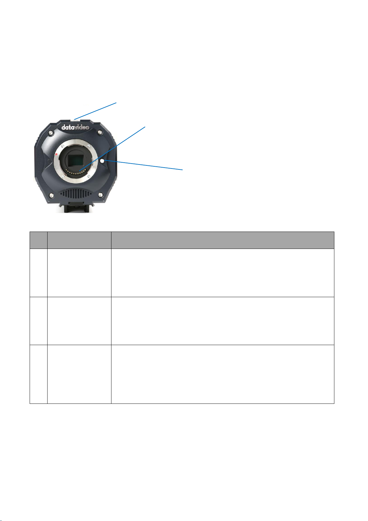
Chapter 3 Connections
No.
Interface
Description
1.
M4/3 lens mount
with standard 11
pin electronic
contacts
This lens mount is used for users to mount the M4/3 compatible
interchangeable lenses such as Panasonic, Panasonic LEICA and
Olympus lenses.
2.
Tally Light
In the EFP production, If a PGM signal is received by the BC-100 from
the switcher, the tally light will light on in red. However, if a PVM signal
is received by the BC-100 from the switcher, the tally light will light on
in green.
3
Lens-release
Button
This lens-release button allows users to remove the lens of the camera.
When the lens-release button is pressed, the lens lock pin will be
retracted and then users can rotate the lens easily. Before installing the
camera lens, please rotate the lens until there is a click to show that
the camera lens is locked properly.
1.
2.
3.
This section will introduce users the connections of Datavideo BC-100 Interchangeable Lens
Camera. Please see following paragraphs for details.
3.1 Front View
9
Page 10
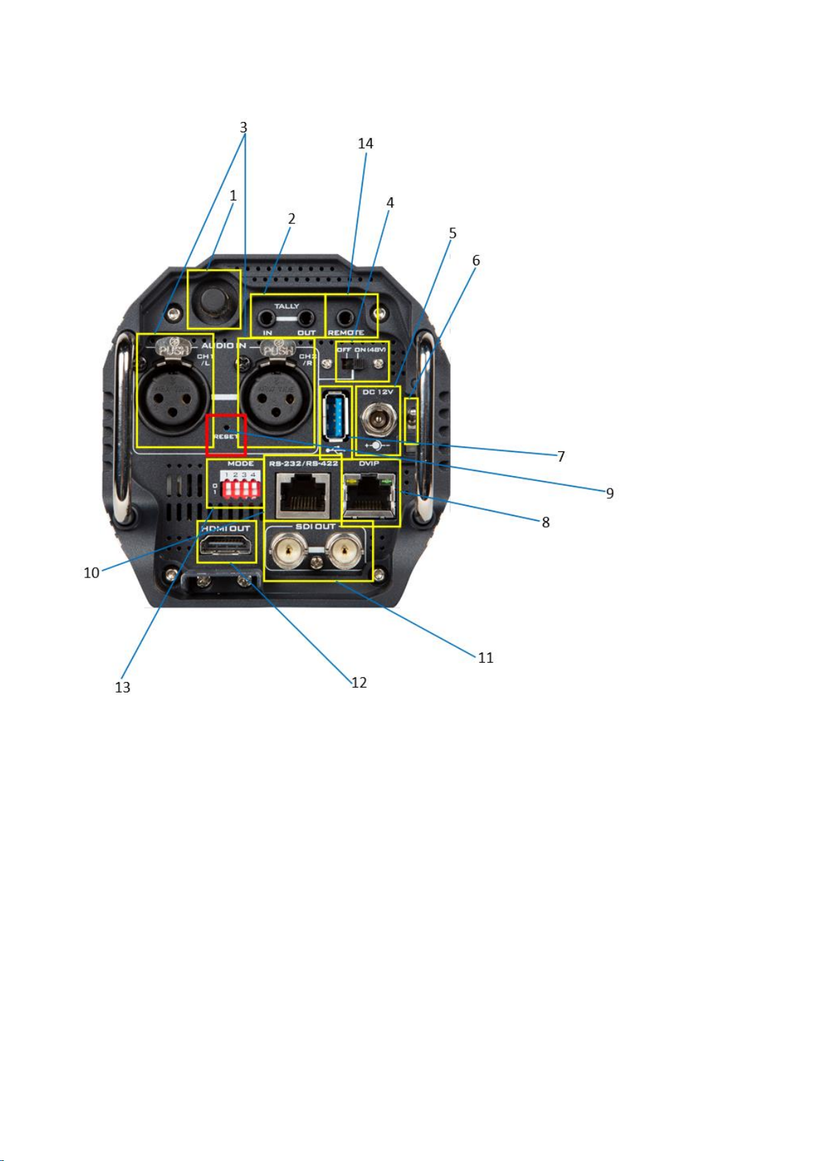
3.2 Rear View
1
3
10
11
12
13
10
Page 11
No.
Interface
Description
1
WiFi Antenna(Optional)
The Wi-Fi function is optional, if the Wi-Fi function is
purchased by the user, this interface can be used to
install the Wi-Fi antenna for transmitting and receiving
the Wi-Fi signal.
2.
Tally IN& Tally OUT
Tally IN is used to receive tally signal from the switcher.
Tally OUT loops out the signal from Tally IN for next
device.
3
XLR Phantom Microphone Inputs
Allows users to input up to two XLR balanced analog
audio sources (CH1/L & CH2/R). Connect these two ports
to external microphones.
Note: If the microphone is the
condenser microphone, please select
the 48V phantom power on the rear
panel of the BC-100 before use, if the microphone is
the dynamic microphone, please turn off the 48V
phantom power.
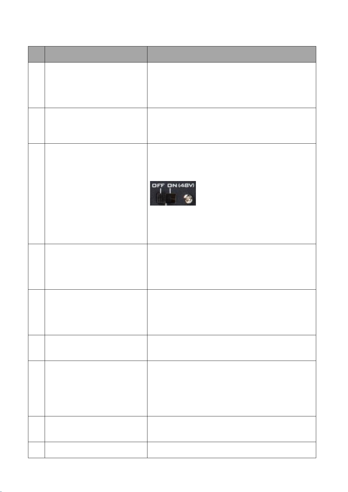
4.
Phantom Power Switch
If the microphone is the condenser microphone, please
turn on the 48V phantom power on the rear panel of the
BC-100 before use, if the microphone is the dynamic
microphone, please turn off the 48V phantom power.
5.
DC 12V Power Connector
DC in socket connects the supplied 12V PSU. The
connection can be secured by screwing the outer
fastening ring of the DC In plug to the socket. The
operating voltage range of the BC-100 is from 7V to 15V.
6.
Power Switch
Turns on/off the 12V power. This power switch provides
delay shutdown function for users.
7.
USB 3.0
This is the USB 3.0 port. Connect the BC-100 to an
Android-based mobile phone for control and preview.
Please pay attention that it is a must to use a USB OTG
cable for connecting this USB 3.0 interface. This USB 3.0
interface supports the Android OS only.
8.
DVIP
This port is used to connect an Ethernet cable to control
the camera through DVIP.
9.
RESET
Press and hold the RESET button for 5 seconds through a
11
Page 12

needle will clear the Wi-Fi password of the BC-100.
10.
RS-232/RS-422
This port is used to connect to an Ethernet cable to
control the camera through the RS-232 or RS-422
protocol.
11.
SDI OUT
These two SDI output connectors can be connected to
different back-end devices such as recorder and lookback monitor. They can be combined with one HDMI
output port on the rear panel of the BC-100 to
simultaneously output two SDI and one HDMI signals
12.
HDMI OUT
This HDMI output connectors can be connected to
different back-end devices such as recorder and lookback monitor. It can be combined with two SDI output
ports on the rear panel of the BC-100 to simultaneously
output one HDMI and two SDI signals
13.
DIP Switch
The 4 position Dip Switch is used for controlling modes
of the BC-100. For the details of the BC-100 dip switch,
please refer to 3.5 DIP Switch of the BC-100.
14.
LANC Remote Control Interface
This remote connector is used for users to connect the
BC-100 to an external recorder such as Atomos Ninjia
Blade 5” HDMI Recorder/Monitor/Player with a 3.5mm
TRS/3 pin plug for remote controlling by LANC interface.
12
Page 13
3.3 Pin Definition of the Tally Cable for Tally IN & Tally OUT
Pin No.
3.5mm Mini-Plug
Signal
1
Tip
RED LED
2
Ring
GREEN LED
3
Sleeve
GND
BC-100 Remote
Please see following table for the pin definition of the Tally IN & Tally OUT of the NH-100.
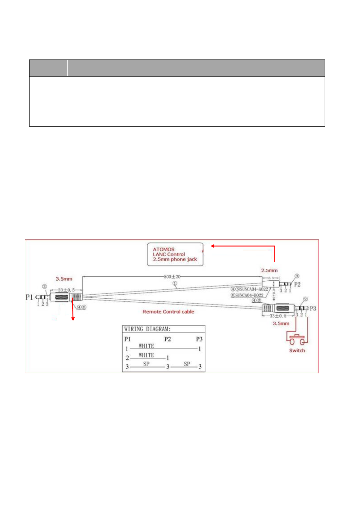
3.4 Pin Definition of the LANC Remote Control
The LANC remote control button (optional) allows users to control an external connected
Recorder/Monitor/Player such as the Atomos Ninjia Blade series with a 3.5mm male to 2.5mm
male & 3.5mm male adapter cable. The main 3.5mm male plug must be connected to the Remote
connector on the rear panel of the BC-100. For the adapter cable, the 2.5mm male plug must be
connected to the LANC connector on the Atomos Recorder/Monitor/Player, and the 3.5mm male
plug must be connected to the 3.5mm connector for “LANC” on the LANC control button. Please
connect the LANC control adapter cable according to following diagram.
13
Page 14

3.5 DIP Switch of the BC-100
BC-100 DIP Switch
Position
Function
Note
1
Reserved for future
extension
Please fix the DIP Switch at 0.
2
Control mode switching
(RS-232/RS-422)
3
Tally signal source
For connecting the BC-100 to the Atomos/BMD
recorder, please slide this position to 0. If the BC100 is connected to a switcher, please slide this
position to 1.
4
LANC control mode
switching
For connecting the BC-100 to the Atomos
recorder, please slide this position to 0.
BC-100 DIP Switch
1 2 3 4
0
Reserved for future
extension
RS-232
Internal Tally
LANC Master
1
RS-422
External Tally
LANC Slave
The 4 position Dip Switch is used for controlling modes of the BC-100. Please refer to following
paragraphs for details of the DIP Switch control.
For the DIP Switch of the BC-100, the position 1 is reserved for future extension, the position 2 is
used for RS-232/RS-422 control mode switching, the position 3 is used for tally signal switching
and the position 4 is used for LANC control mode switching (Master/Slave).
14
Page 15
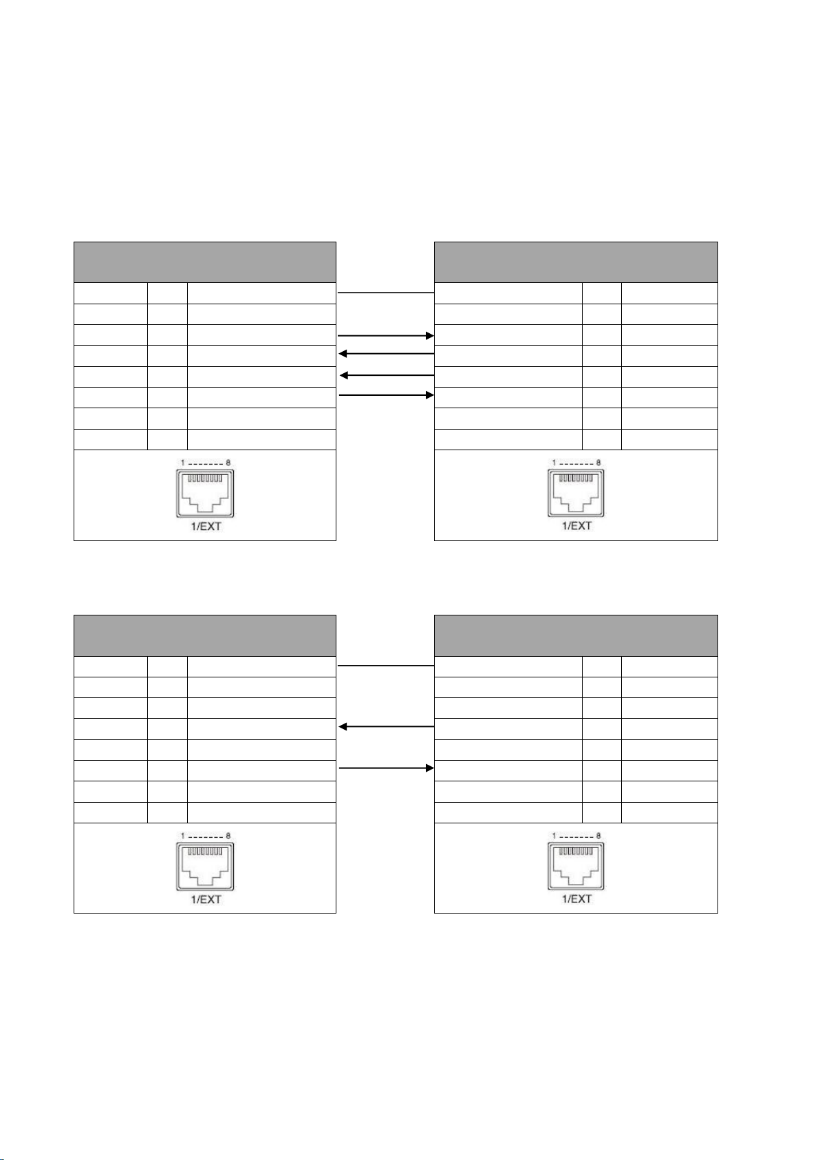
3.6 Direct Connection to Camera
PTZ Camera Controller
(RJ-45 Port)
BC-100 Camera
(RS-422 Port)
GND 1 White/Orange
White/Orange
1
GND
NC
2
Orange
Orange 2 NC
TX- 3 White/Green
White/Green
3
RX-
RX-
4
Blue
Blue 4 TX-
RX+ 5 White/Blue
White/Blue
5
TX+
TX+
6
Green
Green 6 RX+
NC 7 White/Brown
White/Brown
7
NC
NC
8
Brown
Brown 8 NC
PTZ Camera Controller
(RJ-45 Port)
BC-100 Camera
(RS-232 Port)
GND 1 White/Orange
White/Orange
1
GND
NC
2
Orange
Orange 2 NC
NC 3 White/Green
White/Green
3
NC
RX
4
Blue
Blue 4 TX
NC 5 White/Blue
White/Blue
5
NC
TX
6
Green
Green 6 RX
NC 7 White/Brown
White/Brown
7
NC
NC
8
Brown
Brown 8 NC
GND
GND
To use the PTZ Camera Control Unit to directly control the BC-100 camera, connect the RS-422/RS232 port on the camera’s rear panel to the RJ-45 port of the camera control unit by using any RJ45 cable. The RS-422/RS-232 wiring schemes are shown below.
RS-422
RS-232
15
Page 16

3.7 DVIP
Command
Code
Support Levels
Note
ETH_REQ
0x00
Mandatory
Find DVIP devices in the same network.
FWVER_REQ
0x01
Mandatory
Get firmware information of specific (MAC
address) DVIP device.
SET_DHCPMODE
0x02
Mandatory
Set DHCP mode of specific (MAC address)
DVIP device.
SET_IPADR
0x03
Mandatory
Set IP & Gateway address of specific (MAC
address) DVIP device.
RESET
0x04
Mandatory
Request specific (MAC address) DVIP device
to reboot (software reset)
BOOTLOADER
0x05
Optional
Request specific (MAC address) DVIP device
to jump to Boot Loader.
E2P_DEFAULT
0x06
Mandatory
Request specific (MAC address) DVIP device
The Introduction of the DVIP
The concept of the DVIP is to search Davavideo related products and to set the network
configurations of those devices by broadcasting through the UDP socket. After that, the
control commands will be transferred through TCP socket.
How to Connect the BC-100 Camera and the Remote Controller via the DVIP Control
The BC-100 camera can be directly connected to a PC for DVIP controlling through an RJ-45
Ethernet cable.
Broadcast Packet
The UDP is a communication protocol to transfer data to remote host. For transferring data
through the UDP packet, it is a must for you to know the destination IP address and the DVIP
device server (UDP) port number. The PC uses broadcast packet to obtain DVIP device
information in the same network. Please follow following information for the destination IP
address and the DVIP device server (UDP) port number.
Destination IP address: 255.255.255.255
DVIP Device Server(UDP) port number: 5002
For further information of the broadcast packet and the UDP/TCP protocols, please refer to
“Datavideo DVIP Ethernet Control Operation Guide”.
Note: For users who need “Datavideo DVIP Ethernet Control Operation Guide”, please contact
your local Datavideo office or dealer.
3.8 Broadcast and UDP Commands Index
Please see following tables for broadcast/UDP commands Index.
Broadcast Command Index
16
Page 17

to reset to factory default.
E2P_READ
0x07
Vendor-
Dependent
Read EEPROM data from specific (MAC
address) DVIP device.
GET_MODEL
0x40
Mandatory
Get Vendor and Product IP of specific (MAC
address) DVIP device.
GET_MODEL_NAME
0x41
Recommended
Get model name of specific (MAC address)
DVIP device.
GET_VERSION
0x42
Vendor-
Dependent
Get detailed version information of specific
(MAC address) DVIP device.
GET_PRESET_COUNT
0x43
Recommended
Get preset count number of specific (MAC
address) DVIP device
GET_PRESET_NAME
0x44
Recommended
Get preset count number of specific (MAC
address) DVIP device.
Command
Code
Support Levels
Note
ETH_REQ
0x00
Mandatory
Get network information of specific (IP
address) DVIP device
FWVER_REQ
0x01
Mandatory
Get firmware revision of specific (IP address)
DVIP device
SET_DHCPMODE
0x02
Mandatory
Configure DHCP mode of specific (IP address)
DVIP device
SET_IPADR
0x03
Mandatory
Configure IP & Gateway address of specific
(IP address) DVIP device
RESET
0x04
Optional
Request specific (IP address) DVIP device to
reboot (software reset)
RD_E2P
0x05
Vendor-
Dependent
Read EEPROM data from specific (IP address)
DVIP device
WR_E2P
0x06
Vendor-
Dependent
Write EEPROM data to specific (IP address)
DVIP device
RD_IFLASH
0x07
Vendor-
Dependent
Read internal Flash data of specific (IP
address) DVIP device
BOOTLOADER
0x08
Optional
Request specific (IP address) DVIP device to
reboot to Boot Loader
SET_DHCPNAME
0x09
Mandatory
Set DHCP host name of specific (IP address)
DVIP device
SET_MACADR
0x0A
Mandatory
Set MAC address of specific (IP address) DVIP
device
SET_NETMASK
0x0B
Mandatory
Set Net Mask of specific (IP address) DVIP
device
UDP Command Index
17
Page 18

SET_GATEWAY
0x0C
Mandatory
Set Gateway address of specific (IP address)
DVIP device
SET_PRIDNS
0x0D
Mandatory
Set Primary DNS address of specific (IP
address) DVIP device
SET_SECDNS
0x0E
Mandatory
Set Secondary DNS address of specific (IP
address) DVIP device
INIT_E2P
0x0F
Vendor-
Dependent
Initial specific (IP address) DVIP device
configuration data
GET_MODEL
0x40
Mandatory
Get VID & PID of specific (IP address) DVIP
device
GET_MODEL_NAME
0x41
Recommended
Get product name of specific (IP address)
DVIP device
GET_VERSION
0x42
Vendor-
Dependent
Get detailed version information of specific
(IP address) DVIP device
GET_PRESET_COUNT
0x43
Mandatory
Get preset count number of specific (IP
address) DVIP device
GET_PRESET_NAME
0x44
Mandatory
Get preset name of specific preset number of
specific (IP address) DVIP device
RECALL_PRESET
0x45
Mandatory
Recall preset date of specific preset number
of specific (IP address) DVIP device
18
Page 19
Chapter 4 Quick Start Guide
Please follow following steps for quick connection and setting guidance of the BC-100.
Connect the BC-100 camera to the Android handset by the USB OTG Cable
Step1. Please connect the DC 12V power adapter to the DC 12V connector on the rear panel of the
BC-100.
Step 2. Please turn on the BC-100 by the power switch on the rear panel of the BC-100.
Step 3. Please download the BC-100 App from Google Play and then please install the App to your
Android handset.
Step 4. Please use a USB OTG adapter cable (USB Type A (male) to micro USB or USB Type A (male)
to USB Type C) to connect the BC-100 and your Android handset.
Step 5. After that, you can open the BC-100 App.
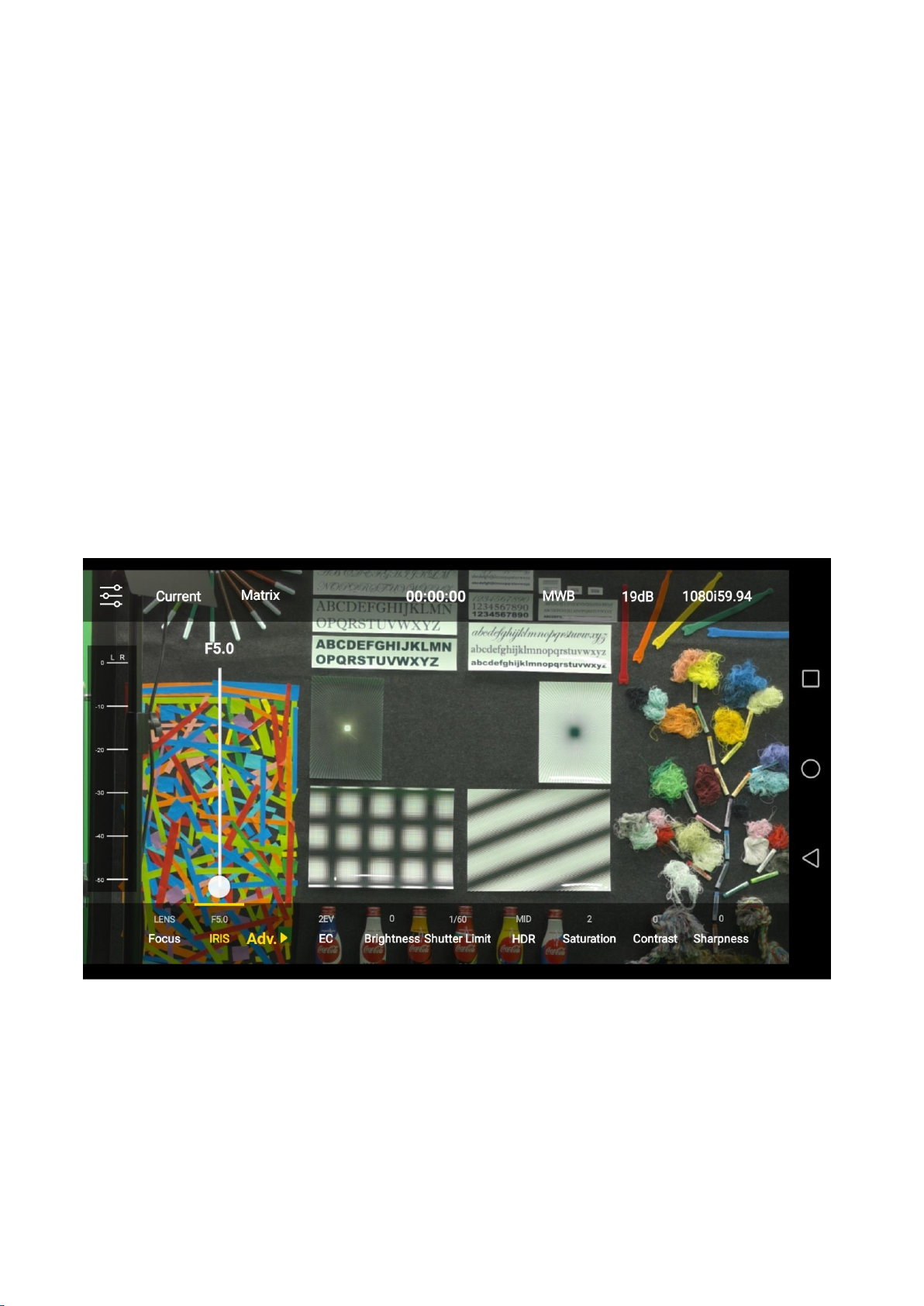
Step 6. After the BC-100 App is launched, the main interface of the App will be shown as following
and then you can control the BC-100 Interchangeable Lens Camera by your handset.
19
Page 20
Note:The Wi-Fi antenna is optional
Connect the BC-100 camera and Android handset by Wi-Fi
Step 1. Please connect the DC 12V power adapter to the DC 12V connector on the rear panel of
the BC-100.
Step 2. Please turn on the BC-100 by the power switch on the rear panel of the BC-100.
Step 3. Please download the BC-100 App from Google Play and then please install the App to your
Android handset.
Step 4. Please turn on the Wi-Fi of your handset and then please search the SSID of the BC-100
camera. The default SSID of the BC-100 camera is “BC-100_xxxx” without password. If users want
to modify the name of the SSID or the Wi-Fi password, please modify those parameters in the BC100 App.
Step 5. After your handset is connected to the BC-100 camera through the BC-100 hotspot, you
can open the BC-100 App.
Step 6. After the BC-100 App is launched, the main interface of the App will be shown as following.
You can control the BC-100 Interchangeable Lens Camera by your handset.
Note:If the Wi-Fi and USB connection are existed together, following screen will be shown for
users to select their desired way for connection.
20
Page 21

Click “Wi-Fi Connection” to enter the main interface of the App directly.
Click “USB Connection” and then the following warning window for USB connection will be
shown. Please click “Use by default for this USB device” and then press “OK” to enter the
main interface of the App.
21
Page 22

Chapter 5. Use BC-100 App to Control the Camera
BC-100 is an Android App for users to control Datavideo BC-100 camera by Android/iOS handsets.
Please follow following steps to control the BC-100 camera by the BC-100 app (Take Android OS as
an example).
Step 1.Take Android handset as an example, please search BC-100 App from Google Play and then
click the install button to install it.
Step 2. After the installation is finished, users can see BC-100 App from the desktop of the handset.
Step 3. Please click the icon to open the BC-100 app. After that, users can see the main interface of
the BC-100 which is shown as following.
5.1 Settings
The settings icon is located at the top-left side of the main interface. This settings icon allows
users to set various functions including 3D Noise Reduction, Audio Level Standard, Audio Level,
Display the Volume Bar, Stream Setting, Connection Mode, Wi-Fi Setting and App Version.
22
Page 23

How to Enter the Settings Menu Options
Please enter setting menu options according to following steps.
Step 1. Please click the settings icon .
Step2. The settings interface which is shown as following will provide users to set several functions
including 3D Noise Reduction, Audio Level Standard, Audio Level, Display the Volume Bar, Stream
Setting, Connection Mode, Wi-Fi Setting and App Version.
23
Page 24

Please set the parameters of settings menu options according to following steps.
3D Noise Reduction :The 3D Noise Reduction option allows users to turn on/off the 3D
noise reduction function.
Step 1. Please press the 3D Noise Reduction option to turn on/turn off the 3D noise reduction
function.
Audio Level Standard:The Audio Level Standard option allows users to select two audio
level standard including SMPTE and EBU.
Step 1. Please press the Audio Level Standard option to select your desired Audio Level Standard
from the drop-down menu.
Audio Level:Audio Level option allows users to adjust the audio level.
Step 1. Users can adjust the audio level by using the audio level setting slider to set the audio level.
The default value of the audio level is 0 and the range for adjustment is from -25 to +25.
Display the Volume Bar:This option allows users to determine whether they want to show
the volume bar on the main user interface of the App or not.
Step 1. Please press the Display the Volume Bar option to turn on or turn off this function.
Stream Setting:The Stream Setting option allows users to set various parameters including
Stream Key, Server URL, Stream Resolution and Bit Rate.
Step 1. Please press the Stream Setting option to open the following Stream Setting menu.
24
Page 25

Step 2. Please press the “Please enter the Stream Key” column on the above diagram to enter the
Stream Key.
Step 3. Please press the “Please enter the Server URL” column on the above diagram to enter the
Stream Server URL.
Step 4. Please press the “Resolution” and “Bitrate” drop down menus on the above diagram to
select your desired resolution and bitrate. After that, please press the “Confirm” button.
Customized Bit Rate
Please follow following steps for setting the customized Bit Rate. (The Bit Rate range that can be
customized by users is from 500 to 3500kbps).
1. Please press the “Customized” option on the above diagram and then the customized
Bit Rate window will be shown as following diagram.
2. After the desired Bit Rate is entered and the “Confirm” button is pressed, the customized Bit
Rate will be saved and then users can go back to the setting interface. If the “Cancel” button is
pressed, users can go back to the setting interface directly.
Step 5. Please press the “Confirm” button which is shown on the above diagram to save the new
settings.
25
Page 26

How to Stream to Youtube Streaming Platform (Take Android Phone as an Example)
Please follow following steps for streaming to Youtube streaming platform by the BC-100 camera.
Step 1. Please make sure that your handset is connected to the public network by the Wi-Fi
connection (If the Wi-Fi of your handset is still connected to the BC-100_xxxx, it is impossible for
users for live-streaming). Moreover, users can also use the 4G mobile network for live-streaming.
Step 2. Please connect your Android handset to the BC-100 camera by a USB-OTG cable.
Step 3. Please open the BC-100 App.
Step 4. Please press the “OK” button to allow the BC-100 App to access the USB device.
Step 5. Users can enter the main interface of the BC-100 App directly.
Step 6. Please go to Google website www.google.com for logging in your Google Account. After
that, please go to Youtube Live website https://www.youtube.com/live_dashboard and then press
the “Stream now” option on the left column.
26
Page 27

Step 7. Please copy the “Server URL” on the lower side of the Youtube Live web page.
Step 8. Please press the settings icon of the BC-100 App and then please press the “Stream
Setting” option.
Step 9. Please paste the “Server URL” on the lower side of the Youtube Live webpage into the
“Please enter the Server URL” column in the “Stream Setting” option of the BC-100 App.
Step 10. Please copy the Stream name/key on the lower side of the Youtube Live web page.
Step 11. Please paste the Stream name/key into the “Please enter the Stream Key” column in the
Stream Setting option of the BC-100 App.
27
Page 28

Step 12. Please press “Resolution” and “Bit Rate” buttons to select your desired resolution and Bit
Rate from the drop-down menus.
Step 13. Please press the “Confirm” button and then users can see that the “Live” icon on the top
side of the BC-100 App becomes red and the live scene can be streamed to the Youtube Live
platform successfully.
Step 14. If users want to stop the live-streaming, please press the “Live” icon again and then the
“Live” icon will become white and the live-streaming will be stopped.
Connection Mode: This option allows users to select two connection modes including Wi-Fi
and USB.
*The selection of the connection mode can be done only when the camera is connected by both
Wi-Fi and USB.
Step 1. Please press the “Connection Mode” option and then the connection
mode setting interface will be shown as following diagram.
28
Page 29

Step 2. Users can select their desired connection mode from the “Connection Mode” option.
Wi-Fi Setting: This option allows users to set the Wi-Fi password (can be used only for Wi-Fi
connection).
Step 1. Users can press the “Wi-Fi Setting” option and then press the “Set” button to set the Name
and Password of the Wi-Fi.
Step 2. After the Password is entered, please press the “Confirm” button to save the password.
App Version: This option allows users to check current App version and to update the latest
BC-100 firmware. Please see “Firmware Update” related chapter for the details of the
firmware update.
29
Page 30

Step 1. Please press the App Version option to show the current BC-100 firmware version which is
shown as following diagram.
5.2 Current
The “Current” option is on the top-left side of the main interface. This option provides users four
main items including “Default”, “User1”, “User2” and “Save”.
How to Enter Current Option
Please follow following options for entering the “Current” option.
Step 1. Please press the “Current” option from the main interface of the App.
Step 2. The setting interface which is shown as following diagram will be shown for users to set
various settings including Default, User1, User2, Save, Export Current Setting and Import Setting.
30
Page 31

Default: Press this key to set the current BC-100 parameters to factory default values.
User 1 and User 2: User 1 and User 2 allow users to adopt pre-saved 2 sets of parameters that
are set by themselves.
Step 1. Please press “User 1” or “User 2” and then the following window will be shown to ask
whether users want to adopt pre-saved user-defined settings or not.
Step 2. Please press the “Confirm” button to load the user-defined setting.
Save: The “Save” button allows users to save 2 sets of user-defined settings.
Step 1. Please set the parameters of the BC-100 in advance.
Step 2. Please press the “Save” button.
Step 3. The “Save Current Setting” window will be shown. Please press “User 1” or “User 2” and
then please press the “Confirm” button to save the preset parameters to “User 1” or “User 2”.
31
Page 32

Export Current Setting: The “Export Current Setting” option allows users to export current
settings.
Step 1. After all parameters are set, please press the Current option on the main interface and
then users can select “Export Current Setting” from the pop-up window.
Step 2. Please enter your desired name for the setting in the “Export Current Setting” pop-up
window. After that, please press the “Confirm” button to export the parameters to the handset
which is used to control the BC-100 for future application.
Import Setting: The “Import Setting” option allows users to import pre-saved parameters.
Step 1. After all parameters are set, please press the “Current” option on the main interface and
then users can select “Import Setting” from the pop-up window.
32
Page 33

Step 2. In the pop-up “Import Setting” window, please select the parameter setting name that
users want to import into the camera and then please press the “Confirm” button to import the
setting into the BC-100 camera.
5.3 Exposure Modes
The Exposure Modes option is located on the option menu bar on the top side of the main
interface. This option provides four Exposure Modes including Matrix Metering, Center-Weighted
Metering, Exposure Lock and Manual Exposure for users.
How to Enter the Exposure Mode Option
Please follow following steps for entering the Exposure Mode option.
Step 1. Please press the Matrix option from the main interface of the BC-100 App.
Step 2. The setting interface which is shown as following diagram will be shown to provide four
exposure modes include Matrix Metering, Center-Weighted Metering, Exposure Lock and
Manual Exposure for users.
33
Page 34

Matrix Metering: The Matrix Metering technology is an automatic exposure technology to
achieve stable exposure status by measuring the average brightness of the whole scene.
Moreover, this technology also takes the photo composition and the change of the subject
location into consideration. The Matrix Metering is a common exposure technology. It
separate the scene of the whole picture into several blocks and each block has its
independent exposure value. After the exposure value of each block is calculated, the
exposure values of all blocks will be combined together for further calculation in order to
provide a final exposure value. The Matrix Metering technology allows users to take a picture
with average brightness to prevent the picture from too bright or too dark. The Matrix
Metering technology is suitable for taking group or scenery pictures in average brightness.
The Matrix Metering exposure technology can be set as default exposure mode.
The Scenarios that is suitable for using the Matrix Metering
A: The scenario for taking pictures has average brightness and the brightness, darkness and
contrast of the picture are moderate.
B: The Matrix Metering can be used in “front light of the subject” and “front side light of the
subject”.
Please follow following steps for using the Matrix Metering.
Step 1. Please press the Matrix Metering option from the main interface of the App.
Step 2. The setting interface which is shown as following diagram will provide four exposure
modes including Matrix Metering, Center-Weighted Metering, Exposure Lock and Manual
Exposure.
Step 3. Please press the Matrix Metering button to finish the setting.
Center-Weighted Metering: The Center-Weighted Metering measures the average brightness
of the whole picture. At the same time, the central area of the picture is emphasized (CenterWeighted Metering). The reason for designing this exposure mode is that for most of the
people, they will put the subject of the photo at the center. The Center-Weighted Metering
34
Page 35

will average the exposure value of the whole picture. However, it will give extra-weighted
calculation for the subject on the central location. So, if the subject of the picture is not
located at the center of the picture (occupy about 30% of the space of the picture), it is not
recommended to use this Center-Weighted Metering.
The Scenarios that is suitable for using the Center-Weighted Metering
A: The subject of the picture is located at the center of the picture.
B: The subject of the picture is back-lighted or is surrounded by glare.
Please follow following steps for using the Center-Weighted Metering.
Step 1. Please press the Matrix Metering option from the main interface of the App.
Step 2. The setting interface which is shown as following diagram will provide four exposure
modes including Matrix Metering, Center-Weighted Metering, Exposure Lock and Manual
Exposure.
Step 3. Please press the Center-Weighted Metering button to finish the setting.
Exposure Lock: After the Exposure Lock button is pressed, the BC-100 will stop light metering
and the light metering value will be kept at the value before the camera is moved. At this
time, no matter how the BC-100 camera is moved, the light metering value will remain
unchanged.
Note: After the Exposure Lock button is pressed, the Gain Limit, Shutter Limit and Exposure
Compensation value can not be adjusted.
The Scenarios that is suitable for using the Exposure Lock
If the contrast between the subject and the background is high (For example: taking pictures for
back-lighted subject or the subject that is beside the window), users can do the light metering at
the point that the subject is with proper brightness. After that, users can lock the Exposure value
before taking pictures. If users want to reduce the brightness of the subject, users can do the light
35
Page 36

metering at the point that the brightness is higher than the subject. After that, users can lock the
Exposure value of the whole screen. If users want to take a picture with brighter subject, users can
do the light metering at the point that is darker than the subject. After that, users can lock the
Exposure value of the whole screen.
Please follow following steps for using the Exposure Lock.
Step 1. Please press the Matrix Metering option from the main interface of the App.
Step 2. The setting interface which is shown as following diagram will provide four exposure
modes including Matrix Metering, Center-Weighted Metering, Exposure Lock and Manual
Exposure.
Step 3. Please press the Exposure Lock button to finish the setting.
Note: After the Exposure Lock button is pressed, the Exposure Compensation function can not be
used.
Manual Exposure: The Manual Exposure mode allows users to set various parameters
including Iris, Shutter and Gain manually.
Please follow following steps for using the Manual Exposure.
Step 1. Please press the Matrix Metering option from the main interface of the App.
Step 2. The setting interface which is shown as following diagram will provide four exposure
modes including Matrix Metering, Center-Weighted Metering, Exposure Lock and Manual
Exposure.
36
Page 37

Step 3. Users can press the Manual Exposure button which is shown as the above diagram for
setting the Shutter and Gain manually.
Step 4. In Manual Exposure Mode, please press the Adv. Option which is shown as following
diagram to show the shutter option for users to adjust the shutter speed manually by the shutter
slider.
37
Page 38

Step 5. In the Manual Exposure Mode, please press the 19dB option which is shown as following
diagram to enter the Gain Limit option to adjust the Gain Limit manually by the Gain Limit slider.
5.4 Recording Status Reminder
The purpose of the Time Code and the Status Reminder are used to remind users about the
recording status. Because the BC-100 interchangeable lens camera does not have the recording
function, so, users need to connect the BC-100 to the external connected recorder such as Atomos
or Blackmagic Design recorder for video recording.
38
Page 39

After the Time Code which is shown as following diagram is pressed by users, there is a recording
reminder window will pop-up to remind users to check that the external connected recorder is
connected successfully and then the video recording can be started.
Because the BC-100 App can not detect that whether the back-end recorder is connected or not,
so, once the external connected optional LANC control button of the BC-100 is pressed, the
recording Time Code timer will be started. In recording process, the red dot which is next to the
recording Time Code will be lighted up. If the recording is terminated, the red dot will disappear.
Note:
1. There is no recording function for the BC-100 camera, the recording reminder and the Time
Code in the App are for reference only.
2. Please remember to check the connection status of the back-end recorder such as Atomos or
Blackmagic Design’s recorder.
3. For confirming the status of the video recording, please check the status of the back-end
external connected recorder.
39
Page 40

5.5 Automatic White Balance (AWB) What is AWB
Human eyes can adjust itself automatically in the nature environment to see the white light.
However, the camera can not do the same thing as the human eyes, so, the color temperature of
the camera must be set in advance before pressing the shutter. The color temperature setting
allows the camera to balance the color temperature and to see the white light. The function of this
setting is the so called “White Balance”.
The AWB option is in the menu bar on the top of the main interface of the App. This option
provides five White Balance modes including AWB, AWB Lock, One Push, MWB and MWB Pro for
users.
How to Enter the AWB Option
Please follow following steps for entering the AWB option .
Step 1. Please press the AWB option from the main interface of the App.
Step 2. The setting interface which is shown as following diagram will be shown to provide five
White Balance modes including AWB, AWB Lock, One Push, MWB and MWB Pro for users to
select.
AWB: Press the AWB button which is shown as the following diagram allows users to adopt
AWB setting by pressing one button only.
AWB (Lock): Users can press the AWB (Lock) button at once after the AWB button is pressed
to lock the current AWB setting.
40
Page 41

One Push: The One Push button allows users to use the One Push White Balance function and
then lock the current WB setting.
MWB: Users can press the MWB button to adjust the desired White Balance color
temperature by the slider which is shown as the following diagram. The adjustable color
temperature range is 2500K to 10000K.
41
Page 42

MWB Pro: Users can press the MWB Pro button in the White Balance menu to adjust the R
Gain and B Gain manually by the slider which is shown in the following diagram.
5.6 Gain/Gain Limit
The Gain of the camera is used to enhance the sensitivity of the CCD component. Users can adjust
the Gain option depending on the change of the brightness of the shooting environment. When
the environment is too dark, users can increase the Gain value and the picture will become
brighter. If the environment is too bright, decrease the Gain value and the picture will become
darker. If the shooting environment has normal brightness, users can set the Gain value in normal
range.
How to Enter the Gain Limit/Manual Gain Option
Please follow following steps for entering the Gain Limit or Manual Gain option.
Step 1. Please press the 19dB option on the main interface of the App.
Step 2. The setting interface which is shown as following diagram will be shown for users to adjust
their desired Gain value manually by the slider.
Note: The adjustment range for the Gain/Gain Limit is 0 to 24 dB. This option will show to be Gain
Limit if the camera is set in automatic exposure modes. Moreover, in Manual Exposure mode, this
option will show to be Manual Gain.
42
Page 43

5.7 Frame Rate
Frame rate means that the camera can record how many pictures within 1 second. If the frame
rate is set to be 60fps, it means that users need to use the 1/60 second or faster shutter speed.
Why? Because if the 1/30 second shutter speed is used, it means that there are only 30 shutters
within 1 second. If the recording format is 60fps, it means every two frame must share the same
picture that is sent by the same shutter. The outcome is the same with 30fps but it needs one time
storage space than the 1/60 second shutter. Moreover, if users want to play this video in slowmotion mode, it can not be played as smooth as the video that is shot by the 60fps format. So, the
shutter speed must be set to be faster than the frame rate. For example, if the frame rate is set to
be 60fps, the shutter speed must be set to be 1/60, 1/120 or 1/180.
How to Enter the Frame Rate Option
Please follow following steps for entering the Frame Rate option .
Step 1. Please press the Frame Rate option (1080p25) from the main interface of the App.
Step 2. The Frame Rate selection button interface which is shown as following diagram will be
shown for users to select their desired Frame Rate.
43
Page 44

Step 3. Press your desired Frame Rate button to finish the Frame Rate setting.
5.8 Focus
The Focus option provides three Focus modes including AF, MF and Lens for users to select their
desired Focus mode.
How to Enter the Focus Option
Please follow following steps for entering the Focus option .
Step 1. Please press the Focus option on the main interface of the App.
Step 2. The Focus Selection buttons interface which is shown as following will be shown for users
to select their desired Focus mode.
44
Page 45

AF: AF is the Auto Focus function. Please follow following steps for using the AF function.
Step 1. Please set the AF/MF switch on the camera lens which is connected to the BC-100 in AF
mode.
Note: If there is no AF/MF switch on the camera lens, it is no need for users to switch the Focus
mode.
Step 2. Please press the AF button in the Focus option to adopt the AF setting.
Step 3. Please press any point on the screen for using the AF function (The Auto Focus Tracking
function is not available).
MF: MF is the Manual Focus function, please follow following steps for using the MF function.
Step 1. Please set the AF/MF switch on the lens of the BC-100 camera to be MF.
Note: If there is no AF/MF switch on the camera lens, it is no need for users to switch the Focus
mode.
Step 2. Please press the MF button in the Focus option to use the MF slider for MF setting. When
the point of the slider is located at the center, push the slider to the up side for Infinity and push
the slider to the down side for the minimum focal length.
45
Page 46

Step 3. After the adjustment is finished, press the MF option again to hide the slider.
The MF button on the main interface: When users press the Focus option and then select the
MF mode, there is a MF button that will be shown beside the Focus option. If you want to
switch from the MF mode to other Focus mode, please press this MF button and then the
Focus option window which is shown as above diagram will be shown for you to switch to
other Focus modes.
46
Page 47

Lens: The Lens option allows users to use the Focus function on the camera lens directly.
Please follow following steps for using the Lens function.
Step 1. Please set the AF/MF switch on the lens of the BC-100 camera to be MF, if there is no
AF/MF switch on the camera lens, it is no need for users to switch the Focus mode.
Step 2. After the Lens option is pressed, users can adjust the Focus ring on the camera lens to set
the Focus point directly.
5.9 IRIS
The IRIS option allows users to adjust the IRIS value. The IRIS value determines how much the incoming
light that will received by the IRIS of the camera. Users can set a low IRIS value for achieving a larger IRIS.
Moreover, a high IRIS value means a smaller IRIS. A lower IRIS value helps users for taking high quality and
bright pictures. Moreover, the IRIS value also affect the Depth of Field of a picture. The “Depth of Field”
means the range that the image is clear. A higher IRIS value can help users to take a picture with the
“Deep Depth of Field” effect. However, a low IRIS value can help users to take a picture with the “Shallow
Deep of Field” effect. The BC-100 App provides the IRIS range from F2.8 to F22 for users to set their desired
IRIS value. The IRIS value is set by reading the IRIS value of the camera lens. If there is no controllable
camera lens that is detected by the App, the IRIS option can not be selected by users.
How to Enter the IRIS Option
Please follow following steps for entering the IRIS option .
Step 1. Please press the IRIS option from the main interface of the App.
Step 2. The IRIS adjustment slider which is shown as following diagram allows users to select their
desired IRIS value.
Step 3. After the adjustment is finished, please press the IRIS option again to hide the slider.
47
Page 48

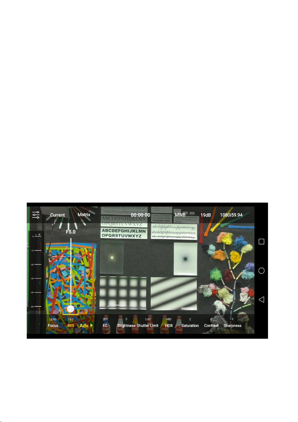
5.10 Advanced Function
The BC-100 App provides several advanced functions for users including EC (Exposure
Compensation), Brightness, Shutter or Shutter Limit, HDR, Saturation, Contrast and Sharpness. In
normal situation, all advanced functions are hidden, users can show those advanced functions by
pressing the Adv. Option which is shown as following diagram.
5.11 EC (Exposure Compensation)
BC-100 provides Exposure Compensation range from -8EV to +8EV for users to adjust the Exposure
Compensation level. No matter which Exposure mode is selected by the user, the camera will
measure the light of the current scenario. After that, an EV level based on the ISO and lightmeasuring formula according to the current scenario will be generated (the total volume of
incoming light). This EV value is generated by the combination of IRIS and Shutter. The purpose of
the Exposure Compensation is that if users do not satisfy for the light-measuring outcome of the
camera, they can adjust the EV value to get an “Expected EV value” for taking a better picture. 0EV
is the default EV value of the camera. +1EV means brighter EV value and -1EV means darker EV
value.
How to Enter the EC Option
Please follow following steps for entering the EC option .
Step 1. Please press the EC option from the main interface of the App.
Step 2. The EC adjustment slider will be shown for users to select their desired EC level.
48
Page 49

5.12 Brightness
The BC-100 provides the Brightness adjustment range from -10 to +10 for users. The Brightness
option allows users to adjust the brightness by a slider. When the slider is set at the negative value,
it will provide contrast for the high-light area. Moreover, the middle tone will become darker
(those areas except high-light and shadow areas). When the slider is set at positive value, the
scenario can be brighter. The brightness adjustment is useful when the Exposure Compensation
may cause the color-fading of the high-light area.
How to Enter the Brightness Option
Please follow following steps for entering the Brightness option .
Step 1. Please press the Brightness option from the main interface of the App.
Step 2. The brightness adjustment slider that is shown as the following diagram allows users to
select their desired brightness value.
49
Page 50

5.13 Shutter or Shutter Limit
When the shutter released button is pressed, the shutter curtain will be opened, and the CMOS
sensor which is behind the shutter curtain will receive the light. The light will penetrate by the IRIS
of the camera. When the shutter is open, the light will irradiate on the CMOS sensor. After that,
the shutter curtain will go back to its original place to cover the CMOS sensor and the light will be
stopped by the shutter curtain. This is the process for taking a picture. The time length that the
CMOS sensor is irradiated by the light is called “Exposure Time”. If the time length is 1 second, it
means that the exposure time is 1 second. Different shutter speed can achieve different function
and performance. Generally speaking, “high shutter speed” can freeze each moment. However,
the slow shutter speed can record the scenario such as the cars are flowing on the road.
How to Enter the Shutter/Shutter Limit Option
Please follow following steps for entering the Shutter Limit Option .
Step 1. Please press Shutter or Shutter Limit option from the main interface of the App.
Step 2. The Shutter/Shutter Limit adjustment slider which is shown as following diagram will be
shown for users to select their desired Shutter/Shutter Limit value.
Note: It is recommended to set the shutter speed to be two times of the frame rate. For example,
if the frame rate is set as 25p, the shutter speed must be set at 1/50. If the frame rate is 29.97p,
the shutter speed must be set at 1/60.
50
Page 51

The BC-100 provides different Shutter/Shutter Limit ranges for different frame rate settings.
24P:1/24, 1/48, 1/72, 1/96, 1/120, 1/144, 1/168, 1/480, 1/960, 1/1920, 1/3840, 1/7200
25P: 1/25, 1/50, 1/75, 1/100, 1/125, 1/150, 1/200, 1/500, 1/1000, 1/2000, 1/4000, 1/8000
29.97P: 1/30, 1/60, 1/90, 1/120, 1/150, 1/180, 1/210, 1/600, 1/1200, 1/2400, 1/4800, 1/9000
50P: 1/50, 1/75, 1/100, 1/125, 1/150, 1/200, 1/500,1/1000, 1/2000, 1/4000, 1/8000
59.94P: 1/60, 1/90, 1/120, 1/150, 1/180, 1/210, 1/600,1/1200, 1/2400, 1/4800, 1/9000
50i: 1/50, 1/75, 1/100, 1/125, 1/150, 1/200, 1/500,1/1000, 1/2000, 1/4000, 1/8000
59.94i: 1/60, 1/90, 1/120, 1/150, 1/180, 1/210, 1/600,1/1200, 1/2400, 1/4800, 1/9000
Note: In Auto Exposure mode, this option will be shown as Shutter Limit. In Manual Exposure
mode, this option will be shown as Manual Shutter.
5.14 HDR (High Dynamic Range)
The BC-100 provides HDR function for users. For the scenarios that the difference between bright
and dark is too huge, the camera will shoot many pictures at the same time with different
exposure value. After that, the camera will composite those pictures to one single picture with
proper bright and dark level without over-exposure and under-exposure.
How to Enter the HDR Option
Please follow following steps for entering the HDR option.
Step 1. Please press the HDR option from the main interface of the App.
Step 2. The HDR adjustment slider which is shown as following diagram will be shown for users to
select their desired HDR value.
51
Page 52

5.15 Saturation
The BC-100 provides Saturation adjustment function for users. The saturation is the strength of
the color. If you want the color to be more intensive, users can increase the saturation. If the
saturation is decreased, the color will be shown as the fading color. The saturation adjustment
range of the BC-100 is from +8 to -8.
How to Enter the Saturation Option
Please follow following steps for entering the Saturation option.
Step 1. Please press the Saturation option on the main interface of the App.
Step 2. The Saturation option adjustment slider which is shown as following diagram will be shown
for users to select their desired saturation value.
52
Page 53

5.16 Contrast
The BC-100 provides the Contrast adjustment function for users. The Contrast is the different
between light and dark. When a higher Contrast value is set by users, the light area will become
brighter and the dark area will become darker for achieving a high clarity picture. If a low Contrast
value is set, the difference between the light area and the dark area will be tiny and the clarity of
the picture will be decreased. The Contrast adjustment range for the BC-100 is from 0 to +16.
How to Enter the Contrast Option
Please follow following steps for entering the Contrast option.
Step 1. Please press the Contrast option from the main interface of the App.
Step 2. The Contrast adjustment slider which is shown as following diagram will be shown for
users to select their desired Contrast value.
53
Page 54

5.17 Sharpness
The BC-100 provides Sharpness adjustment function for users. Sharpness is used to find the profile
of the object for sharpening the lines of the profile. Moreover, it can enhance the contrast for
creating the feeling of sharpening. The Sharpness adjustment range for the BC-100 is from 0 to 7.
How to Enter the Sharpness Option
Please follow following steps for entering the Sharpness option.
Step 1. Please press the Sharpness option on the main interface of the App.
Step 2. The Sharpness adjustment slider which is shown as following diagram will be shown for
users to select their desired Sharpness value.
54
Page 55

Chapter 6. Firmware Update (Take Android Phone as an Example)
Users can use the BC-100 App to update the latest firmware for the BC-100 HD Interchangeable
Lens camera.
Step 1. Before the firmware update procedure is started, please make sure that the BC-100 App is
installed in your Android handset.
Step 2. Please turn on the power of the BC-100 camera.
Step 3. Please find the Wi-Fi hotspot “BC-100_xxxx” from the Wi-Fi setting menu of your handset.
Please press the Wi-Fi hotspot to connect your handset to the BC-100 camera.
Step 4. After the handset is connected to the BC-100 successfully, please open the BC-100 App.
Step 5. And then users can enter into the main interface of the BC-100 App which is shown as
following diagram.
55
Page 56

Step 6. Please press the setting icon to enter the setting interface which is shown as following
diagram.
56
Page 57

Step 7. Please press the App Version option and then the current firmware version will be shown.
Step 8. Please press “Current BC-100 firmware version” for 7 times and then the “Latest
Firmware Version” reminder which is shown as following diagram will be shown. Please press the
“Update” button to start the firmware update.
57
Page 58

Step 9. Please press “Update” button and then the firmware update will be started and the
progress bar which is shown as following diagram will be shown.
Step 10.
When the firmware update is done successfully, the firmware update successful reminder
window which is shown as following will be shown.
58
Page 59

If the firmware update is not done successfully or there is no network connection available, a
reminder window will be shown to remind users to do the firmware update procedure again.
Chapter 7. Optional Accessories
Datavideo provides LANC control button for users to be the optional accessory of the BC-100
Interchangeable Lens camera. The BC-100 can combine with the recorder/monitor/player devices
such as the Atomos Ninjia Blade for achieving the monitoring and recording purposes. The
recording function can be realized by the remote control of the optional LANC remote control
button. Moreover, for the optional LANC remote control button, please contact with your local
dealers or the Datavideo office.
59
Page 60

Chapter 8. Dimensions
Unit:millimeters (mm)
60
Page 61

Chapter 9. Specification
Model Name
BC-100
Product Name
Interchangeable Lens Camera
Video Format
1080p 24/25/29.97/50/59.94
1080i 50/59.94
Image Sensor
4/3" CMOS Sensor
Camera Lens Ring
System
Micro Four Third (M4/3)
Image Processing
Capability
12 bit (24p/25p/29.97p)
10 bit (50p/59.94p/50i/59.94i)
Effective Pixels
About 20.89 Mega Pixel
S/N Ratio
60dB
Min. Illumination
0.1Lux
Electronic Shutter
1/25 (1/24, 1/30), 1/50 (1/48, 1/60), 1/75 (1/72, 1/90), 1/100 (1/96,
1/120), 1/125 (1/120, 1/150), 1/150 (1/144, 1/180), 1/200 (1/168,
1/210), 1/500 (1/480, 1/600), 1/1000 (1/960, 1/1200), 1/2000 (1/1920,
1/2400), 1/4000 (1/3840, 1/4800), 1/8000 (1/7200, 1/9000) Sec.
Zoom Ratio
The value is determined by the camera lens(the camera lens is not
included when shipping)
Gamma Control
Dynamic Adjustment
Exposure
Auto/Lock/Manual
IRIS Setting
Manual
Digital Noise Reductions
3D Noise Reduction
Dynamic Range Control
High/Middle/Low/OFF
Language
Traditional Chinese/Simplified Chinese/English(Control by App)
White Balance
AWB/One Push WB/Lock/MWB
AGC/ Gain Control
Auto (AGC) / Manual
Max. Gain Limit
Mirror/Image Flip
N/A
Focus Mode
Control by App (push-auto/manual), Control by Camera Lens
Focal Length
The value is determined by the camera lens(the camera lens is not
included when shipping)
Angle of View
The value is determined by the camera lens(the camera lens is not
included when shipping)
Image Compensation
Auto
Image Output
HDMI x 1 & SDI x 2
Audio Input
Supports dual XLR microphone input and can be embedded in Video
for output
Tally LED
Dual Color, Red/Green
Remote Control
Interface and
Transmitting Range
RS-232: 12m
RS-422: Transmit up to 1000m
DVIP (RJ-45): 100m
Wi-Fi: 5m
USB(OTG): 0.5m
Firmware Update
Control by App(Wi-Fi)
IR Control
N/A
61
Page 62

Camera Control Device
Android / iOS phone
Tripod Screw Hole Size
1/4-20 UNC
RoHS
Compliant
Video Output
Video Output
HDMI x 1 & SDI x 2
Control
Communication
Protocol
VISCA Protocol/DVIP/RS-232/RS-422
Remote Control
Wi-Fi(Optional) & USB-OTG。RS-422/RS-232/DVIP through RJ-45
interface
Firmware Update
By BC-100 App
Others
Operating Temp.
0°C ~ 40°C(32°F~104°F)
Storage Temp.
- 10°C ~ 60°C (14°F~140°F)
Operating Humidity
10 % to 80 % (non-condensing)
Storage Humidity
10 % to 80 % (non-condensing)
Power
DC 12V 2A
Power Consumption
20.88W
Color
Dark Blue
Dimension (W x H x D)
101 x 104 x 198(mm)
Optional Accessories
External Connected
Recording Controller
Supports LANC interface external connected recorder remote control
button
* Micro Four Thirds and Micro Four Thirds Logo marks are trademarks or registered trademarks of Olympus Imaging Corp., in Japan, the United
States, the European Union and other countries.
*VISCA is the trademark of Sony Corporation.
*Atomos is the trademark of the Atomos Global Pty. Ltd.
*Blackmagic Design is the trademark of the Blackmagic Design Pty Ltd.
* All trademarks are the property of their respective owners
62
Page 63

Note
63
Page 64

Jul.-12.2019
Version E2
Datavideo Technologies Co., Ltd. All rights reserved 2020
https://www.datavideo.com/product/BC-100
 Loading...