

Page 1
Audio Mixer
AD-200
Quick Start Guide
www.datavideo.com
Page 2

Warranty
Standard Warranty
• Datavideo equipment is guaranteed against any manufacturing defects for one year from the date of purchase.
• The original purchase invoice or other documentary evidence should be supplied at the time of any request for
repair under warranty.
• Damage caused by accident, misuse, unauthorized repairs, sand, grit or water is not covered by this warranty.
• All mail or transportation costs including insurance are at the expense of the owner.
• All other claims of any nature are not covered.
• Cables & batteries are not covered under warranty.
• Warranty only valid within the country or region of purchase.
• Your statutory rights are not affected.
Two Year W a rranty
• All Datavideo products purchased after 01-Oct.-2008 qualify for a free one year extension to the standard
Warranty, providing the product is registered with Datavideo within 30 days of purchase. For information on how
to register please visit www.datavideo-tek.com or contact your local Datavideo office or authorized Distributors
• Certain parts with limited lifetime expectancy such as OLED Panels, DVD Drives, Hard Drives are only covered
for the first 10,000 hours, or 1 year (whichever comes first).
Any second year warranty claims must be made to your local Datavideo office or one of its authorized Distributors
before the extended warranty expires.
Disposal
For EU Customers only - WEEE Marking
This symbol on the product indicates that it will not be treated as household waste. It must
be handed over to the applicable take back scheme for the recycling of electrical and
electronic equipment. For more detailed information about the recycling of this product,
please contact your local Datavideo office.
Packing List
1 x AD-200 Main Unit
1 x AD-200 Control Unit
1 x Accessory List
1 x AD-200 Quick Start Guide
- 2 -
Page 3
Connections & Controls
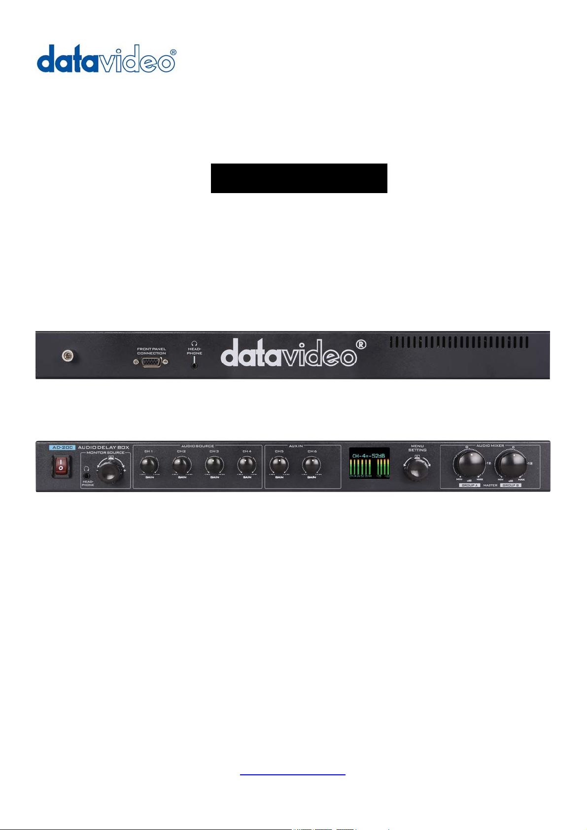
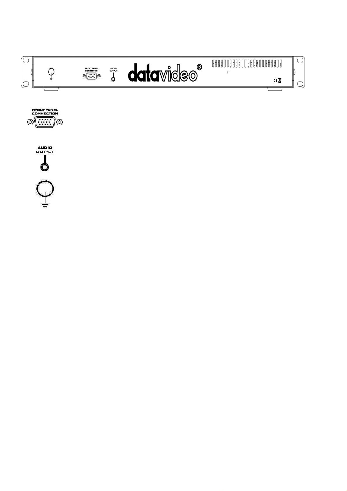
Main Unit (Front Panel)
Connection
Use the D-SUB Cable to connection AD-200 main unit and AD-200 control unit.
Audio Output
Use the connect cable to connection AD-200 main unit and AD-200 control unit.
Grounding Terminal
When connecting this unit to any other component, make sure that it is properly grounded by
connecting this terminal to an appropriate point. When connecting, use the socket and be sure to
use wire with a cross-sectional area of at least 1.0 mm
2
.
- 3 -
Page 4
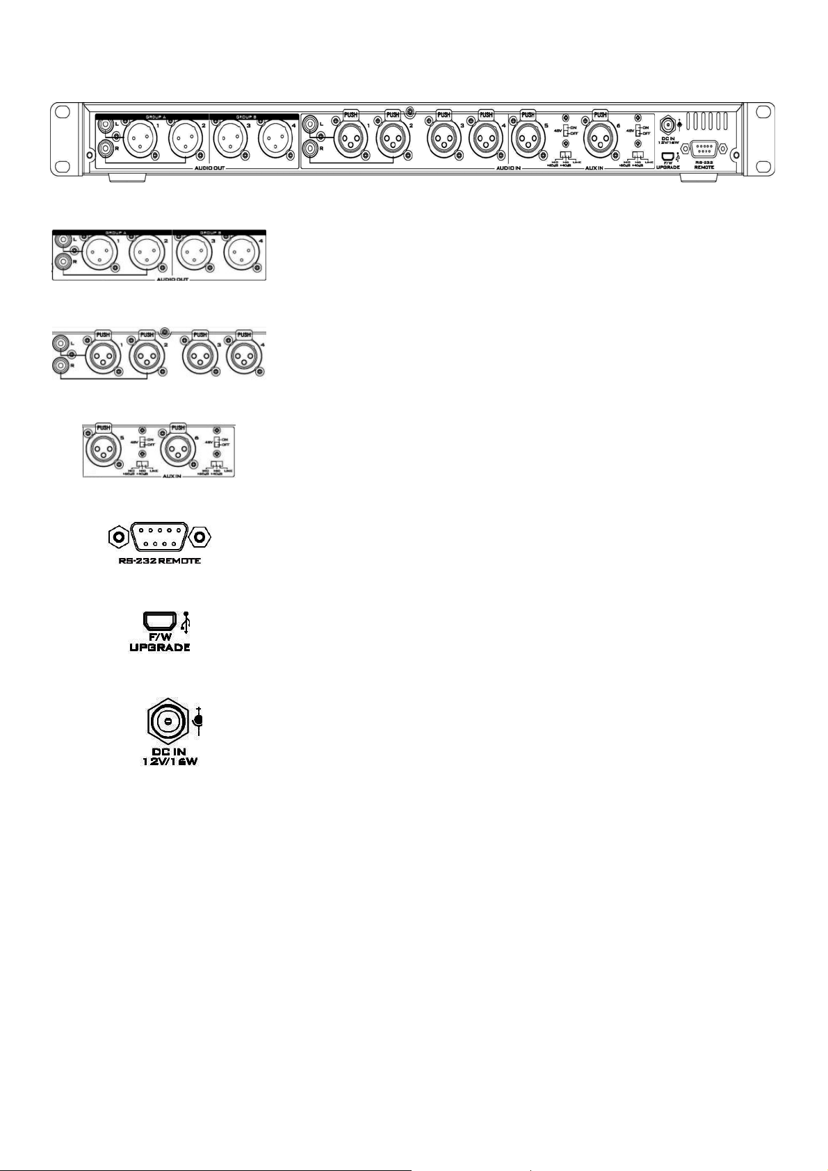
Main Unit (Rear Panel)
Audio Output
RCA audio output & 4 channels XLR balanced audio output (You can use ch1,
2 audio out is XLR or RCA).
Audio input
RCA audio input & 4 channels XLR balanced audio input (You can use ch1, 2
audio input is XLR or RCA )
AUX Audio Input
2 channels XLR balanced audio input.
For more information please see page 7 for more details.
RS-232 REMOTE
To be updated.
USB
Firmware Upgrades
DC IN Socket
Connect the supplied 12V PSU to this socket. The power connection can be
secured by screwing the outer fastening ring of the DC In plug to the socket.
- 4 -
Page 5

Control Unit (Front Panel)
Power Switch
Switches the power On / Off.
Headphone
Accepts a stereo mini jack plug for stereo headphones. The headphone
volume is adjusted by the rotating Head phone volume control.
Headphone Volume Control
Controls Headphone volume level.
Use the Headphone section to accurately monitor any of the sources output.
Push this button can switch audio source 1~6 and audio output 1, 2.
Audio Input Source Level Controls
The AD-200 controls audio input channel (CH1~CH6).
This row of audio channel selection buttons has OLED built in to show which
input channel is active. Level control for each audio input source is via the
rotary pots above each of the audio channel selection buttons.
(Level range from -80dB to +20dB)
OLED Panel
Audio Meters & Function Display.
MENU Navigation Button
Rotate to change options and press in to select.
For more information please see the Menu Function.
Audio Output Source Level Controls
GROUP A = Control the CH1,2 output volume.
GROUP B = Control the CH3,4 output volume.
- 5 -
Page 6

Control Unit (Rear Panel)
Connection
Use the D-SUB Cable to connection AD-200 main unit and AD-200 control unit.
Audio Input
Use the connect cable to connection AD-200 main unit and AD-200 control unit.
DC IN Socket
Connect the supplied 12V PSU to this socket. The power connection can be secured by screwing
the outer fastening ring of the DC In plug to the socket.
Note: AD-200 main unit and AD-200 control unit both have DC IN Socket, they are the same
function, you just need select one socket to supply the power input.
Grounding Terminal
When connecting this unit to any other component, make sure that it is properly grounded by
connecting this terminal to an appropriate point. When connecting, use the socket and be sure to
use wire with a cross-sectional area of at least 1.0 mm2.
- 6 -
Page 7

Connection AD-200 main unit and AD-200 control unit
AD-200 Main Unit
Audio Inputs and Levels
Connect Cable
D-SUB Cable
AD-200 Control Unit
There are two kinds of switches under AUDIO IN:
The LINE/ MIC+40dB/ MIC+60dB switch is used to set the audio as LINE in or MIC+40dB or MIC+60dB in. When
LINE in is selected please also set the 48V ON/OFF switch to OFF in order to prevent burn-out damage to the circuit.
The 48V ON/OFF switch is for phantom power. If you want to use MIC in, please set the LINE/ MIC+40dB/ MIC+60dB
switch first, and then if using a Condenser microphone turn ON the 48V ON/OFF switch. If you wish to use a Dynamic
microphone please turn OFF the 48V ON/OFF switch.
*NOTE: Always double check the manual for the microphone being used to see what advice it gives regarding
power as some Mics have internal batteries too.
- 7 -
Page 8

Menu Function
1: SET MIXER
+ :
- :
1~6 :
T :
OUT1~4 :
Enable
Disable
Audio Input (CH1~6)
Tone
Audio Output (CH1~4)
This table are setting to be:
Out1 is input1 audio mixed
Out2 is input1~6 audio mixed
Out3 is input2 audio mixed
Out4 is tone mixed
2: DELAY TIME
This function can be setting audio input delay time from 0000~3000 m SEC.
3: TONE MODE
1. FQ. : This function is setting TONE frequency 1KHz, 6KHz or 12 KHz
2. LEL : This function is setting TONE level from 00~24 dBu.
4: DISPLAY
1. BRI. : This function is setting OLED panel brightness.
2. TEST : You can select different color (Red, Green, Blue, Black, White) to test OLED panel
3. MODE : This function is setting OLED panel display CH1/2, CH3/4, CH5/6, OUT1/2, OUT3/4 or all channels
volume indicator .
- 8 -
Page 9

System Diagram
- 9 -
Page 10

Specifications
Parameter Specification Limit Units Conditions/Comments
AUX IN
MIC/Line Connectors (CH5~CH6) 3Pin XLR Female Pin2=(+),Pin3=(-),Pin1=GND
Mic/Line Input Impedance(CH5/CH6) 6.8K/300K Ω
Mic Gain Range off to +20 ±3 dB Audio source GAIN(knob)
Line Gain Range off to +20 ±3 dB Audio source GAIN(knob)
THD+N 0.01 max % @1KHz,0dB(Lin IN)
Line in Max Level +23dBu ±3% dBu
Signal to noise ratio 75 min dB @1KHz,0dB(Lin IN)
Frequency Response 20Hz~20KHz ±3 dB
Audio IN
Input (CH1~CH4)
Connectors 3Pin XLR Female Pin2=(+),Pin3=(-),Pin1=GND
Input Impedance 300K Ω
Gain Range off to +20 ±3 dB Audio source GAIN(knob)
Signal to noise ratio 75 min dB @1KHz,0dB
THD+N 0.01 max % @1KHz,0dB
Frequency Response 20Hz~20KHz ±3 dB
unbalanced mono audio (L, R) RCA
Signal to noise ratio 80 min dB @1KHz,0dB(RCA IN)
THD+N 0.01 max % @1KHz,0dB(RCA IN)
Impedance 20K 1% Ω
Audio Output
Connector (1,2,3,4)(Group A,B) 3Pin XLR Male Pin2=(+),Pin3=(-),Pin1=GND
Impedance 60 1% Ω
Gain Range off to +20 ±3 dB OUTPUT (Group A.B)(knob)
Output Max Level +23dBu ±1.5% dB
unbalanced mono audio (L, R) RCA
Gain Range off to +20 ±3 dB OUTPUT (Group A.B)(knob)
Impedance 300 1% Ω
Headphone
Connector 3.5mm phone jack Tip(+),Ring=(-),Sleeve=GND
Signal to noise ratio 70 min dB @1KHz,0dB(Lin IN)
THD+N 0.01 max % @1KHz,0dB(Lin IN)
Frequency Response 20Hz~20KHz ±3 dB
Others
Phantom Power +48V ±3% VDC
Power Consumption 12V/19W ±3% watts
Power Input connector 2pin DC Jack Pin4=(+),Pin1=GND
Dimensions (Main Unit) 147 x 440 x 45.4 ±1% mm L X W X H
Dimensions (Control Unit) 90.5 x 440 x 47.5 ±1% mm L X W X H
Weight Main Unit 1.8kg / Control Unit 1.1kg kg
OLED 1,77" TFT 160XRGBX128
Audio Delay for audio input 0~3 sec
- 10 -
Page 11

Notes
- 11 -
Page 12

Service & Support
It is our goal to make owning and using Datavideo products a satisfying experience. Our support staff is available to
assist you to set up and operate your system. Contact your local office for specific support requests. Plus, please visit
www.datavideo.com
to access our FAQ section.
USA: Datavideo Corporation
Tel: +1 562 696 2324 Fax: +1 562-698-6930 E-Mail: techsupport@datavideo.us
The Netherland: Datavideo Technologies Europe BV
Tel: +31-30-261-96-56 Fax: +31-30 261-96-57 E-Mail: service@datavideo.nl
United Kingdom: Datavideo UK Limited
Tel: +44 1457 851 000 Fax: +44 1457 850 964 E-Mail: sales@datavideo.co.uk
Taiwan: Datavideo Technologies Co., Ltd
Tel: +886 2 8227 2888 Fax: +886-2-8227-2777 E-mail: service@datavideo.com.tw
China: Datavideo Technologies China Co., Ltd
Tel: +86 21-5603 6599 Fax:+86 21-5603 6770 E-mail: service@datavideo.cn
Singapore: Datavideo Technologies (S) PTE LTD
Tel: +65-6749 6866 Fax: +65-6749 3266 E-mail: sales@datavideo.sg
Hong Kong: Datavideo HK Limited.
Tel: +852 2833 1981 Fax: +852-2833-9916 E-mail: info@datavideo.com.hk
France: Datavideo France
Tel: +33 1 60 37 02 46 Fax: +33 1 60 37 67 32 E-Mail: info@datavideo.fr
India: Datavideo India
Tel: +91-0120-2427337 Fax: +91-0120-2427338 E-Mail: sales@datavideo.in
All the trademarks are the properties of their respective owners.
Datavideo Technologies Co., Ltd. All rights reserved 2018
Feb-20.2014 P/N: G082060559B1
- 12 -
 Loading...