


USER GUIDE AND MANUAL
Encoder-Modulator with ASI
MODEL: DT-IPTV-QAM-ASI-2H
Dual Input HD Digital
Version 1.0
Last Update: 01-15-2019
DT-IPTV-QAM-ASI-2H | Manual V1.0 | 01152019

NACE Brands is the leading brand of satellite downlink products, cable headend systems,
• 24/7/365 Live Technical Service Support
fiber optics, wire, cable, and related connectivity products with integrators. With a global
presence in cable and satellite infrastructure products and multimedia technology systems,
NACE Brands is the brand of choice for the cable and satellite distribution industry.
Having been in business for over 25 years, NACE brands has become the partner of choice for
many integrators. Integrators choose NACE Brands because of our exceptional live technical
service, our industry leading sales and technical support, and our full portfolio of
complimentary product lines. We know that we can help you with any projects you have
because we have the people, the experience, and the products to be the integrator’s choice.
• Expertly Trained and Highly Knowledgeable Sales and Support Team
• Full Product Line of Cable and Satellite Infrastructure Products
• Customized Site-Survey Process to Ensure Project Success
2 DT-IPTV-QAM-ASI-2H | Manual V1.0 | 01152019

Table of Contents
Safety Precautions .......................................................................................................................................... 4
Package Contents ........................................................................................................................................... 5
Product Description........................................................................................................................................ 6
Specifications ................................................................................................................................................. 7
Installation ...................................................................................................................................................... 8
Unpacking and Inspection .................................................................................................................... 8
Hardware Installations and Connections ........................................................................................................ 8
DEVICE Programming and Setup ................................................................................................................. 9
Encoder Programming and Setup via GUI Interface: .......................................................................... 9
Overview Page of DATA-TRONIX Encoder ............................................................................................... 10
Login Password: ................................................................................................................................. 10
Common Setup ............................................................................................................................................. 11
RF Setup ....................................................................................................................................................... 12
Encoder Setup .............................................................................................................................................. 13
IP Streaming Setup ....................................................................................................................................... 15
Network Configuration ................................................................................................................................ 16
Administration ............................................................................................................................................. 17
Saving your configuration files .................................................................................................................... 18
Front Panel LCD Encoder Menu Map ......................................................................................................... 19
Modulator Configuration via Front Panel LCD ................................................................................. 20
Common Setup Menu ......................................................................................................................... 21
RF Setup Menu ................................................................................................................................... 21
Encoder Setup Menu .......................................................................................................................... 22
IP Streaming Setup ....................................................................................................................................... 25
Network Setup .................................................................................................................................... 25
Streaming Setup ................................................................................................................................. 26
ASI Output ......................................................................................................................................... 27
ASI Output ......................................................................................................................................... 27
EAS .............................................................................................................................................................. 27
Product Notes: .............................................................................................................................................. 29
Warranty ............................................................................................................................................. 29
3 DT-IPTV-QAM-ASI-2H | Manual V1.0 | 01152019

Safety Precautions
The presence of this symbol: is to alert the installer and user to the presence of uninsulated dangerous
voltages within the product’s enclosure that may be of sufficient magnitude to produce a risk of electric
shock.
TO REDUCE THE RISK OF FIRE OR ELECTRIC SHOCK, DO NOT EXPOSE THIS DEVICE TO RAIN
OR MOISTURE. DO NOT OPEN THE UNIT. REFER SERVICING TO QUALIFIED PERSONNEL ONLY.
DO NOT apply power to the unit until all connections have been made, all components have been
installed and all wiring has been properly terminated.
DO NOT terminate, change or uninstall any wiring without first disconnecting the unit’s power adapter
from the device.
This device is supplied with the appropriately rated power supply. The use of any other power supply
could cause damage and invalidate the manufacturer’s warranty.
DO NOT connect the power cord to the device if the power cord is damaged.
DO NOT cut the power cord.
DO NOT plug the power cord into an AC outlet until all cables and connections to the device have
been properly connected.
The device should be installed in an environment consistent with its operating temperature
specifications. Placement next to heating devices and ducts is to be avoided as doing so may cause
damage. The device should not be placed in areas of high humidity.
DO NOT cover any of the device’s ventilation openings.
DO NOT cover or obstruct the device’s fan or fan openings.
If the device has been in a cold environment allow it to warm to room temperature for at least 2 hours
before connecting to an AC outlet.
4 DT-IPTV-QAM-ASI-2H | Manual V1.0 | 01152019

Package Contents
This package contains:
One DT-IPTV-QAM-ASI-2H HD Digital Encoder-Modulator
One power cable
User Guide and Manual
Inspect the package before starting installation to ensure there is no damage and all supplied contents are
present. Contact your distributor or dealer should the device be damaged or package contents are
incomplete.
5 DT-IPTV-QAM-ASI-2H | Manual V1.0 | 01152019

Product Description
DATA-TRONIX's DT-IPTV-QAM-ASI-2H Encoder/Modulators simultaneously provide a QAM, ASI,
and IP output stream making it ideal for any Commercial RF or IP Networks. The high quality HD design
allows for watching action packed movies and sports channels on any HDTV. The space saving design
delivers 2 High Quality HD QAM/IP/ASI channels in a single 1RU space.
Front panel LCD Display for easy installation
High Resolution 1080i/1080p
VCN Mode for Virtual Channel Mapping
Composite, Component, and HDMI (unencrypted) inputs
MPEG2 or MPEG4 (AVC) Video Output
Selectable Constellation
Closed Captioning Support
+40dBmV Output
Newly Added EAS Functionality
Rack mountable 1RU height
Images of Front and Rear Panels
6 DT-IPTV-QAM-ASI-2H | Manual V1.0 | 01152019
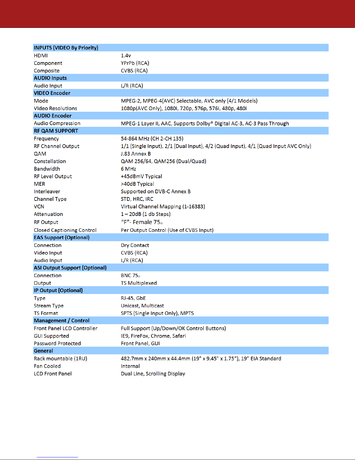
Specifications
*Subject to change without notifications
*Manufactured under License of Dolby Laboratories
7 DT-IPTV-QAM-ASI-2H | Manual V1.0 | 01152019

Installation
System Installer must adhere to Article 820-40 of the NEC that provides guidelines for proper
grounding and specifies that the cable ground shall be connected to the grounding system of the
building, as close to the point of cable entry as possible.
Unpacking and Inspection
Each unit is shipped factory tested. Ensure all items are removed from the container prior to discarding
any packing material.
Thoroughly inspect the unit for shipping damage with particular attention to connectors and controls. If
there is any sign of damage to the unit or damaged or loose connectors contact your distributor
immediately. Do not put the equipment into service if there is any indication of defect or damage.
Hardware Installations and Connections
It is highly recommended that quality cables and connectors be used for all video and audio
source connections.
1. The unit is designed to be rack mounted in a standard EIA 19” rack.
2. The unit comes standard with HDMI, Component, and Composite video inputs. The encoder /
modulator are intelligently designed to detect the video input from the video source. HDMI
Connection: Connect the HDMI cable(s) from the video source(s) into the HDMI input(s). If
using a Component Video Cable, connect the Y (Green), Pb (Blue), and Pr (Red) video source
cable to the unit’s Component input ports. If using a Composite Video source, use a 75Ω coaxial
cable with RCA connectors to connect the video source (e.g., CATV, DVD, VCR, Camera) to the
unit’s CVBS port (IN1,IN2).
Repeat this step for each video source connection.
3. Component / Composite Audio inputs: Connect A/V audio input (Left / Right Audio) use RCA
cables to connect the audio source to the red / white AUDIO L and AUDIO R INPUT jacks
(IN1,IN2). Repeat this step for each audio source connection.
Be sure the video and audio connections for each source are consistent with the unit’s inputs
(IN1,IN2).
4. Use a quality 75Ω coaxial cable with “F” connectors from the unit’s RF OUT jack to the
distribution system (combiner or reverse splitter) or directly to a television.
5. If your device is equipped with an IP output- connect the Ethernet cable to the IP output RJ45
connector.
6. If your device is equipped with an ASI output- connect the BNC cable to the ASI output.
7. If your device is EAS equipped make the proper connections (contact replay and Video /Audio
Inputs) to the EAS device.
8. Connect the included power cord to the unit’s POWER plug.
9. Connect the power cord to an appropriately rated AC power outlet.
8 DT-IPTV-QAM-ASI-2H | Manual V1.0 | 01152019

DEVICE Programming and Setup
To setup and program the Encoder you can use the GUI interface or the LCD Front Panel
Connecting to the GUI Interface:
1. Connect an Ethernet cable directly (no Cross Over cable required) to the Web Management Port
on the rear panel of the encoder or connect the Ethernet cable to an Ethernet switch. Connect an
Ethernet Cable to your PC.
2. Using a Windows-based PC Select Windows Icon
3. Go to My Computer
4. Select Network
5. Allow UPnP to locate and list the device(s) in the right panel (Windows XP or prior)
6. Right Click and Select “View device Webpage”.
Note: To setup the encoder using the Front Panel LCD see “Modulator Configuration via
Front Panel LCD”.
Encoder Programming and Setup via GUI Interface:
After connecting the device to the “Web Management” port located on the rear of the device and locating
the device via the 'Network' tool in 'My Computer'
Step 1: Right Click and Select “View device Webpage”
9 DT-IPTV-QAM-ASI-2H | Manual V1.0 | 01152019

Overview Page of DATA-TRONIX Encoder
Welcome page showing overview status of the Encoder when fully functioning.
Step 2: Login
Select Common Setup
Once the Common Setup Tab is selected you will be prompted to enter the user name and
password for device.
Login Password:
Default User Name: admin
Default Password: Admin123
Note: To change the Password for the GUI go to the Administration Tab
10 DT-IPTV-QAM-ASI-2H | Manual V1.0 | 01152019

Step 3: Common Setup Tab
Common Setup
Use the Common Setup Page to set the Output channel, Attenuation, Enable VCN Mode, and Device
Address.
Step 4: Local Save
Perform a Local Save once all parameters are set.
Notes on Changes:
Changes made to an individual setup tab may require the installer to perform a Local Save AND Upload
and Reboot to the device if you are only making changes to one parameter of the encoder.
Example: Installer is required to change only the output channel for the device (No other changes to the
device are required). Once the channel has been changed, the installer is required to perform
1) Local Save AND
2) Upload and Reboot.
11 DT-IPTV-QAM-ASI-2H | Manual V1.0 | 01152019

Step 5: RF Setup
RF Setup
Use the RF Setup Page to setup each RF Output.
Select and set the required parameters you require for your installation.
Step 6: Local Save
Perform a Local Save once all parameters are set.
12 DT-IPTV-QAM-ASI-2H | Manual V1.0 | 01152019

Step 7: Encoder Setup
Encoder Setup
13 DT-IPTV-QAM-ASI-2H | Manual V1.0 | 01152019

Select the Encoder 1, 2 tab to program an individual encoder. Select and change all desired parameters.
NOTE: There will be an Encoder tab present for each input on the device.
Step 8: Local Save for each Encoder tab
Perform a Local Save on EACH Encoder Tab where changes were performed.
***** Ensure all Encoder tab changes have been locally saved
14 DT-IPTV-QAM-ASI-2H | Manual V1.0 | 01152019
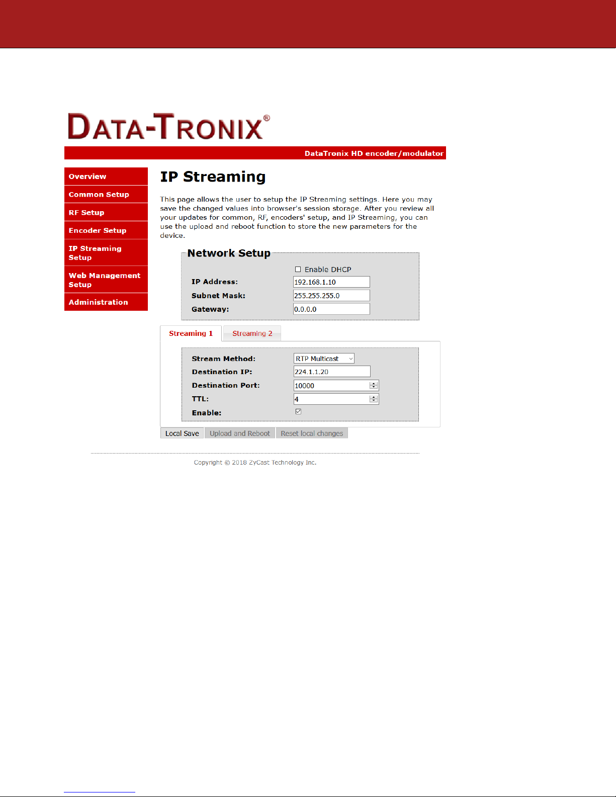
Step 9: IP Streaming
IP Streaming Setup
** Your device may not be IP Streaming capable- if not move to the next step.
Use the IP Streaming setup page to set your device's IP streaming IP Address, and select your streaming
method protocol and Destination IP, Port, and TTL settings.
Step 10: Local Save
Perform a Local Save once all parameters are set.
***** Ensure all Encoder changes have been locally saved before performing Step 11.
15 DT-IPTV-QAM-ASI-2H | Manual V1.0 | 01152019

Step 11: Upload and Reboot
Once all the encoder's settings are changed and a Local Save performed for each Setup tab
Select “Upload and Reboot” on the IP Streaming page. This function will upload and save all parameters
set in the Common, RF, Encoder, IP Streaming sections of the device. Your device will quickly reboot.
Reminder: If changing only a setting on a specific setup page- remember to perform a Local Save and
Upload and Reboot.
We highly recommend you save your encoder configuration files. See Administration tab for how to
backup your settings.
Step 12: Network Configuration Tab
Network Configuration
Use the Network Setup Tab to configure the device’s IP address, Subnet Mask, Gateway, Enable/Disable
DHCP, and set Host Name.
Step 13: Save Network Configuration
Save Config: Once all parameters are set you are required to select Save Config. This function
will reboot and save the changes setting for the Network Configuration.
Note: Only the Network Configuration changes will be saved.
16 DT-IPTV-QAM-ASI-2H | Manual V1.0 | 01152019

Step 14: Administration
Administration
17 DT-IPTV-QAM-ASI-2H | Manual V1.0 | 01152019

Administration Page Functions
Actions
Reboot
Reboot device. All unsaved settings will be lost.
Reset to Default
Reset all settings back to original factory settings
Backup
Download all settings of device
Upload
Upload a saved config file
New Password
Create and save new password for GUI
****Caution****
Selecting “Reset to Default” will automatically reset all saved settings back to factory default
settings. All saved settings will be lost.
****Caution****
Step 15: If required- change GUI Password and Submit.
Note: When setting a new password you must use the Submit button.
This password is for access to the GUI only. The LCD front Panel Password will not be changed and is
set to prevent unauthorized users access to your device.
Saving your configuration files
We highly recommend you save your encoder configuration files. Simply Click the “Backup”
button and the configuration files will be saved to your computer.
To upload a configuration file simply click “Choose File” then locate the file you want to upload. Click
“Upload” to install the configuration files. This function is helpful to the installer when installing a large
number of encoders in a single system.
18 DT-IPTV-QAM-ASI-2H | Manual V1.0 | 01152019
Main Menu
Common
RF Setup
Encoder
Exit
IP Streaming
Output
Attenuation
VCN Mode
Channel
ASI TS ID
Default
Select RF
Enable RF
Constellation
Regional
Interleaver
Device
RF Output
RF TS ID
Video Setup
Select
Audio Setup
Color Setup
PID Setup
Network
Streaming
Back to Main
Back to Main
DHCP
Web Mngt
IP Address
Subnet Mask
Gateway
Network
Streaming
DHCP
IP Address
Subnet Mask
Gateway
Back to IP
Setup
Select IP
Enable
Streaming
Back to IP
(IP Streaming Sub Menus)
PSIP Setup
Destination
Back to Main
Back to Main
Back to Main
Destination
Time to Live
Video Setup
Video
Input
Video
Output
HD Video
Closed
SD Video
Output Bitrate
Aspect
HDCP
Audio Setup
Audio
Audio
(Encoder Setup Sub Menus)
Back to
Back to
PID Setup
IP TS
ID
PMT
PID
Video
PID
Audio
PCR
Back to
PSIP Setup
VCN (Major
CH No)
VCN (Minor
Program
Num
Short
Long CH
Source ID
Back to
VCN
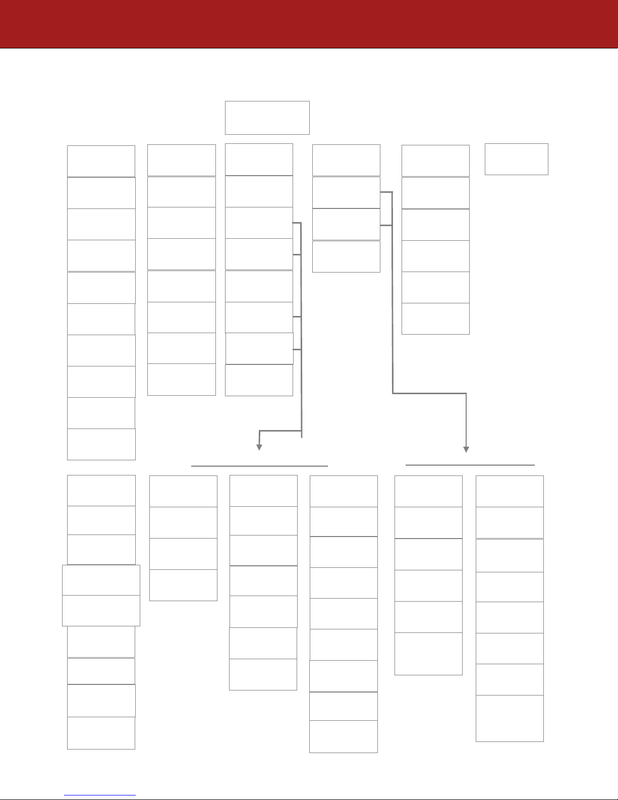
Setup Using Front Panel LCD
Front Panel LCD Encoder Menu Map
Setup
Channel
Type
Name
Address
Config
Menu
Output Bitrate
Ratio
caption
Encoder
19 DT-IPTV-QAM-ASI-2H | Manual V1.0 | 01152019
Menu
Input
Output
Encoder
Setup
Encoder
Menu
PID
PID
Encoder
Setup
Setup
Setup
Menu
CH No)
(One Part)
Name
Name
Encoder
Network Setup
Setup Menu
Streaming
Setup Menu
Output
Streaming
Method
IP
Port
Streaming
Setup

Modulator Configuration via Front Panel LCD
Once the encoder is powered up it will go through its initial booting process. Once the unit has completed
its initial “Booting” up process the LCD will display IN-1..., Bit Rate information, MY-DTV1...., and
other information in the LCD Display Window. When visible the unit is ready for programming or
operation.
The LCD will display data as it cycles through the available information.
Screen Views:
1: Inputs, Mbps, Channel Names, Video Output Type, Audio Output type
IN-1 4.466Mbps MY-DTV1 H.264 MP2
IN-2 4.466Mbps MY-DTV2 H.264 MP2
2: Use the Scroll Up/Down button to display RF-1 data, Physical Output Channel, Constellation, and
Interleaver.
RF-1 102(663.0000 MHZ) QAM 256 I128, J1
3: Use the Scroll Up/Down button to display IP address
1st DESTINATION IP 224. 1. 1. 20
1st DESTINATION PORT 10000
Main Menu – To access the Main Menu first enter the password by pressing the OK button. Use
the Scroll Up/Down buttons to enter the password. Once the password is entered press the OK
button again and the LCD Screen will display “Main Menu Common Setup”.
Password – Use the Scroll Up/Down buttons to enter the password. Password is 0000. Press the
OK button for each number to enter the password. Press OK again after the display shows …...
HD Series.
PASSWORD=?
0
20 DT-IPTV-QAM-ASI-2H | Manual V1.0 | 01152019

Common Setup Menu
Output Channel – Use the Scroll Up/Down button to change the output channel. Use the
Common Setup MenuScroll Up/Down buttons to select the desired Output Channel. Once
the desired output channel is selected press the OK button to set the channel.
The LCD Display will show both the channel number and the frequency number of the
output channel (example: 102 663.0000MHz)
Attenuation – Use the Scroll Up/Down button to select Attenuation. Press the OK button
to enter the Attenuation menu. Use the Scroll/Up down button to select the desired
attenuation in 1dB increments from 0 to minus 20 dB. Once the desired attenuation level is
found press the OK button to set.
VCN Mode - To enable Virtual Channel Number / Mapping Scroll to VCN Menu. Press
OK to enter the VCN menu. Select the desired VCN Mode, VCN(Major & Minor) Auto,
VCN(Major & Minor) Manual, or VCN(One Part) Manual. Press OK button to set.
Channel Type – Use the Scroll Up/Down button to select Channel Type. Press the OK
button to enter the Channel Type menu. Menu options are STD, HRC and IRC. Factory
default: STD. Use the Scroll Up/Down button to select the desired Channel Type and press
the OK button to set.
Regional Name - Note: Do not Change. Skip this function. Default: USA.
Device Address – Use the Scroll Up/Down button to select Device Address. Press the OK
button to enter the Device Address menu. Use the Scroll Up/Down to select the Desired
Address ranging from 1 to 255 then press OK to set. A unique device address is required if
setting up more than 1 encoder per site. This allows the user to distinguish each device.
ASI TS ID – Use the Scroll Up/Down button to select ASI TS ID. Press the OK button to
enter the ASI TS ID menu. Use the Scroll Up/Down to select the Desired ID ranging from
1 to 65535 then press OK to set. Factory Default: 5000.
Default Configuration –To reset the Encoder/Modulator back to the factory default select
the Default Configuration Menu. Press OK to enter the Default Configuration Menu.
Using the Up/Down button select YES to reset all programmed settings back to the factory
default setting. Factory Default: NO.
Caution: Once the “YES” button is pressed the unit will automatically reset to the
factory default settings. All settings or changes to the encoder/modulator will be lost.
Back to Main- Select Back to Main to escape the Common Setup Menu.
RF Setup Menu
Select RF- The Single and Dual versions of this product will have Select 1 only.
Enable RF- Use the Scroll UP/Down button to select Enable RF. Press the OK button to
enter the Enable RF Menu. Select Enable or Disable then press the OK button to set.
Factory Default: Enable.
Constellation – Use the Scroll Up/Down button to select Constellation. Press the OK
button to enter the Constellation menu. Factory Default: QAM256.
21 DT-IPTV-QAM-ASI-2H | Manual V1.0 | 01152019

Interleaver- Use the Scroll Up/Down button to select the appropriate Interleaver selection.
Press the OK button to enter the Interleaver menu. Use the Scroll Up/Down button to
select the desired Interleaver value and press the OK button to set. Factory default: I=128,
J=1.
RF Output – Use the Scroll Up/Down button to select RF Output. Press the OK button to
enter the RF Output menu. Options are Normal, Inverted, or C.W. Factory default: Normal.
Use the Scroll Up/Down button to select the desired RF Output and press the OK button to
set.
RF TS ID – Use the Scroll Up/Down button to select RF TS ID. Press the OK button to
enter the RF TS ID menu. Use the Scroll Up/Down button to select the desired ID ranging
from 1 to 65535 then press the OK button to set.
Back to Main- Select Back to Main to escape the RF Setup Menu.
Encoder Setup Menu
Select Encoder- Use the OK button to enter the Select Encoder Menu. Using the Scroll
Up/Down buttons select the encoder you wish to program. Use the OK button to set the
Encoder. Select Encoder 1 or 2, then press OK button to set.
Once Selected the Display will indicate which Encoder you are programming while in the
setup function
ENCODER SETUP 1
SELECT ENCODER
Video Setup- Use the Scroll Up/Down button to select Video Setup Menu. Press the OK
button to enter the Video Setup menu. Set the Video Setup using the Scroll Up/Down
buttons to set Video Input, Video Output, HD Video Output Bitrate, SD Video Output
Bitrate, Aspect Ratio, HDCP, and Closed Caption.
Video Input- Use the Scroll Up/Down button to select Video Input Menu. Press the OK
button to enter the Video Input Menu. Use the Scroll Up/Down to select the Desired Video
Input option: Auto, HDMI, Component, or Composite then press OK to set. Factory
Default: Auto.
The Encoder/Modulator is designed with Intelligent Input Detection (IID) technology. If
you select Auto, the unit will detect the video input.
Video Output- Use the Scroll Up/Down button to select Video Output Menu. Press the
OK button to enter the Video Output Menu. Use the Scroll Up/Down to select the Desired
Video Output, H.264 CBR or MPEG 2 CBR then press OK to set. Factory Default: H.264
CBR.
Note: The Dual Input allows the installer to select a combination of Video Output formats.
Some versions of this device will allow the user to have both outputs broadcasting in either
MPEG2 or AVC (MPEG4) or a combination of both MPEG2 and AVC (MPEG4).
22 DT-IPTV-QAM-ASI-2H | Manual V1.0 | 01152019

HD Video Output Bitrate- Use the Scroll Up/Down button to select Video Output Bitrate
Menu. Press the OK button to enter the Video Output Bitrate Menu. Use the Scroll
Up/Down to select the Desired HD Video Output Bitrate, ranging from 2000 to 10000.
Factory Default: 8000.
SD Video Output Bitrate- Use the Scroll Up/Down button to select Video Output Bitrate
Menu. Press the OK button to enter the Video Output Bitrate Menu. Use the Scroll
Up/Down to select the Desired SD Video Output Bitrate, ranging from 1000 to 4000.
Factory Default: 4000.
Aspect Ratio – Use the Scroll Up/Down button to select Aspect Ratio. Press the OK
button to enter the Aspect Ratio menu. Use the Scroll Up/Down button to select the desired
Aspect Ratio option of 4:3 or 16:9 then press the OK button to set. Factory default: 16:9.
HDCP- Use the Scroll Up/Down button to select the HDCP menu- Use the Scroll
Up/Down button to select the HDCP menu. Press the OK button to enter the HDCP menu.
Select Enable / Disable. Each Encoder will require you to Enable the HDCP option.
NOTE: It is the installers / property owner / integrator's responsibility to contract
with the service provider regarding content authorization and the use of HDCP.
Closed Caption- Use the Scroll Up/Down button to select the Closed Caption Menu. Press
the OK button to enter the Closed Caption menu. Enable / Disable Closed Caption control.
Each Encoder will require you to Enable the Closed Caption option if you require Closed
Captioning Support on a particular video output.
NOTE: WHEN USING CLOSED CAPTIONING- USER MUST CONNECT FROM THE
CONTENT SOURCE THE COMPOSITE OUTPUT OR CC OUTPUT SOURCE TO THE
ENCODER'S CVBS INPUT CONNECTOR.
Back to Encoder- Select Back to Encoder to escape the Video Setup Menu.
Audio Setup- Use the Scroll Up/Down button to select Audio Setup Menu. Press the OK
button to enter the Audio Setup menu. Set the Audio Setup using the Scroll Up/Down
buttons to set Audio Input, Audio Output.
Audio Input – Use the Scroll Up/Down button to select Audio Input. Press the OK button
to enter the Audio Input menu. Use the Scroll Up/Down button to select the Audio Input
option: Auto or Analog. Factory Set: Auto.
Audio Output – Use the Scroll Up/Down button to select Audio Output. Press the OK
button to enter the Audio Output menu. Use the Scroll Up/Down button to select the Audio
Output option: MP2 (MPEG2 Layer I Audio), AC3, or AAC. Factory default: MP2. Press
the OK button to set.
Back to Encoder- Select Back to Encoder to escape the Audio Setup Menu.
Color Setup- Use the Scroll Up/Down button to select Color Setup Menu. Press the OK
button to enter the Color Setup menu. Set the Color Setup using the Scroll Up/Down
buttons to set.
23 DT-IPTV-QAM-ASI-2H | Manual V1.0 | 01152019

Brightness – Use the Scroll Up/Down button to select Brightness. Press the OK button to
enter the Brightness menu. Use the Scroll Up/Down button to select the desired Brightness
value (0 to 255) and press the OK button to set. Factory default: 128.
Contrast – Use the Scroll Up/Down button to select Contrast. Press the OK button to enter
the Contrast menu. Use the Scroll Up/Down button to select the desired Contrast value (0
to 255) and press the OK button to set. Factory default: 128.
Saturation – Use the Scroll Up/Down button to select Saturation. Press the OK button to
enter the Saturation menu. Use the Scroll Up/Down button to select the desired Saturation
value (0 to 255) and press the OK button to set. Factory default: 128.
Hue – Use the Scroll Up/Down button to select Hue. Press the OK button to enter the Hue
menu. Use the Scroll Up/Down button to select the desired Hue value (0 to 255) and press
the OK button to set. Factory default: 128.
Back to Encoder- Select Back to Encoder to escape the Color Setup Menu.
PID Setup- Use the Scroll Up/Down button to select PID Setup Menu. Press the OK
button to enter the PID Setup menu. Set the PID Setup using the Scroll Up/Down buttons
to set IP TS ID, PMT PID, VIDEO PID, AUDIO PID, and PCR PID.
IP TS ID - Use the Scroll Up/Down button to set IP TS ID. Press the OK button to enter
the IP TS ID setup menu. Use the Scroll Up/Down to select the desired IP TS ID ranging
from 32 to 8186 then press OK to set. Factory Default: 1000.
PMT PID - Use the Scroll Up/Down button to set PMT PID. Press the OK button to enter
the PMT PID setup menu. Use the Scroll Up/Down to select the desired PMT PID ranging
from 32 to 8186 then press OK to set. Factory Default: 4178.
VIDEO PID - Use the Scroll Up/Down button to set VIDEO PID. Press the OK button to
enter the VIDOE PID setup menu. Use the Scroll Up/Down to select the desired VIDEO
PID ranging from 32 to 8186 then press OK to set. Factory Default: 4176.
AUDIO PID - Use the Scroll Up/Down button to set AUDIO PID. Press the OK button to
enter the AUDIO PID setup menu. Use the Scroll Up/Down to select the desired AUDIO
PID ranging from 32 to 8186 then press OK to set. Factory Default: 4177.
PCR PID - Use the Scroll Up/Down button to set PCR PID. Press the OK button to enter
the PCR PID setup menu. Use the Scroll Up/Down to select the desired PCR PID ranging
from 32 to 8186 then press OK to set. Factory Default: 4176.
Back to Encoder- Select Back to Encoder to escape the PID Setup Menu.
PSIP Setup- Use the Scroll Up/Down button to select PSIP Setup Menu. Press the OK
button to enter the PSIP Setup menu. Set the PSIP Setup using the Scroll Up/Down buttons
to set VCN(MAJOR CH NO), VCN(MINOR CH NO), VCN(ONE PART), Program Num,
Short Name, Long CH Name, and Source ID.
VCN(MAJOR CH NO) - Use the Scroll Up/Down button to set VCN(MAJOR CH NO).
Press the OK button to enter the VCN(MAJOR CH NO) setup menu. Use the Scroll
Up/Down to select the desired VCN(MAJOR CH NO) ranging from 1 to 999 then press
OK to set. Factory Default: 102.
24 DT-IPTV-QAM-ASI-2H | Manual V1.0 | 01152019

VCN(MINOR CH NO) - Use the Scroll Up/Down button to set VCN(MINOR CH NO).
Press the OK button to enter the VCN(MINOR CH NO) setup menu. Use the Scroll
Up/Down to select the desired VCN(MINOR CH NO) ranging from 1 to 999 then press
OK to set. Factory Default: 1.
VCN(ONE PART) - Use the Scroll Up/Down button to set VCN(ONE PART). Press the
OK button to enter the VCN(ONE PART) setup menu. Use the Scroll Up/Down to select
the desired VCN(ONE PART) ranging from 1 to 999 then press OK to set. Factory Default:
101.
PROGRAM NO - Use the Scroll Up/Down button to set PROGRAM NO. Press the OK
button to enter the PROGRAM NO setup menu. Use the Scroll Up/Down to select the
Program Num ranging from 1 to 999 then press OK to set. Factory Default: 1.
Short Channel Name – Use the Scroll Up/Down button to select Short Channel Name.
Press the OK button to enter the Short Channel Name menu. Use the Scroll Up/Down
menu to select the first character of the desired Short Channel Name then press the OK
button to set. Repeat the process until the Short Channel Name is completed. If the
modulator has more than one video input scroll through the Advanced Menu for additional
Short channel name menus.
The Short Name can be 7 characters long. Factory Default: MY-DVT1/MY-DVT2.
Long Channel Name – Use the Scroll Up/Down button to select Long Channel Name.
Press the OK button to enter the Long Channel Name menu. Use the Scroll Up/Down
menu to select the first character of the desired Long Channel Name then press the OK
button to set. Repeat the process until the Long Channel Name is completed. If the
modulator has more than one video input scroll through the Advanced Menu for additional
Long channel name menus. Factory Default: ATSC-Digital-TV1/ATSC-DIGITAL-TV2.
The Long Channel Name can be 16 characters long.
Source ID - Use the Scroll Up/Down button to set Source ID. Press the OK button to enter
the Source ID menu. Use the Scroll Up/Down to set the Source ID. Range: 1 to 65535.
Press OK to set. Factory Default: 101.
Back to Encoder- Select Back to Encoder to escape the PSIP Setup Menu.
IP Streaming Setup
Network Setup
DHCP – Use the Scroll Up/Down button to select DHCP. Press the OK button to enter the
DHCP menu. Use the Scroll Up/Down button to Enable/Disable. Press the OK button to set.
IP Address – Use the Scroll Up/Down button to select IP Address. Press the OK button to
enter the IP Address menu. Use the Scroll Up/Down button to enter the IP address. Use the
Scroll Up/Down menu to select the first number of the desired IP Address then press the
OK button to set. Repeat the process until the IP Address is completed. Press the OK
button to set. Note: If DHCP is enabled you will not be able to set an IP address. Select
DHCP disabled if Static IP Address required.
IP Address Range(s):
(1) 10.0.0.0 ~ 10.255..255.255
(2) 172.16.0.0 ~ 172.31.255.255
25 DT-IPTV-QAM-ASI-2H | Manual V1.0 | 01152019

(3) 192.168.0.0 ~ 192.168.255.255
Subnet Mask – Use the Scroll Up/Down button to select Subnet Mask. Press the OK
button to enter the Subnet Mask menu. Use the Scroll Up/Down button to enter the Subnet
Mask. Use the Scroll Up/Down menu to select the first number of the desired Subnet Mask
then press the OK button to set. Repeat the process until the Subnet Mask is completed.
Press the OK button to set.
Gateway Address – Use the Scroll Up/Down button to select Gateway Address. Press the
OK button to enter the Gateway Address menu. Use the Scroll Up/Down button to enter
the Gateway Address... Use the Scroll Up/Down menu to select the first number of the
desired Gateway Address then press the OK button to set. Repeat the process until the
Gateway Address is completed. Press the OK button to set.
Back to IP Streaming Setup - Select Back to IP Streaming Setup to escape the Network -
IP Streaming Sub Menu.
Streaming Setup
Select IP Output – Use the Scroll Up/Down button to select Select IP Output. Press the
OK button to enter the Select IP Output menu. Use the Scroll Up/Down button to select the
desired IP Output, 1 or 2. Press the OK button to set.
Enable Streaming – Use the Scroll UP/Down button to select Enable Streaming. Press the
OK button to enter the Enable Streaming Menu. Select Enable or Disable then press the
OK button to set. Factory Default: Enable.
Streaming Method – Use the Scroll Up/Down button to select Streaming Method. Press
the OK button to enter the Streaming Method menu. Use the Scroll Up/Down button to
select the Streaming Method required. Select: RTP UNICAST, UDP UNICAST, RPT
MULTICAST, or UDP MULTICAST. Press the OK button to set. Factory Default: RTP
Multicast.
Destination IP – Use the Scroll Up/Down button to select Destination IP (Address). Press
the OK button to enter the Destination IP Address menu. Use the Scroll Up/Down button
to set the Destination IP Address. Note: By selecting Unicast in the Streaming Method
Menu the default address begins at 192.168.1.20. Use the Scroll Up/Down button to set the
Destination IP Address. Press the OK button to set. Multicast begins at 224.1.1.1. Press
the OK button to set.
Destination IP Address Range(s):
Unicast: 0.0.0.0 ~ 223.255.255.255
Multicast: 224.0.0.0 ~ 239.255.255.255
Destination Port – Use the Scroll Up/Down button to select DES Port Number
(Destination Port Number). Press the OK button to enter the Destination Port Number
menu. Use the Scroll Up/Down button to set. Press the OK button to set. Factory Default:
10000.
Time To Live – Use the Scroll Up/Down button to select Time To Live menu. Press the
OK button to enter the Time To Live menu. Use the Scroll Up/Down button to select TTL.
Press the OK button to set. Default Settings: Unicast: 63. Multicast: 4. TTL Range: 1~ 255.
Back to IP Streaming Setup- Select Back to IP Streaming Setup To escape the Streaming
- IP Streaming Sub Menu.
26 DT-IPTV-QAM-ASI-2H | Manual V1.0 | 01152019

ASI Output
IP Address – Use the Scroll Up/Down button to select IP Address. Press the OK button to
Gateway Address – Use the Scroll Up/Down button to select Gateway Address. Press the
DH C P – Use the Scroll Up/Down button to select DHCP. Press the OK button to enter
the DHCP menu. Use the Scroll Up/Down button to Enable/Disable. Press the OK button
to set.
enter the IP Address menu. Use the Scroll Up/Down button to enter the IP Address. Use the
Scroll Up/Down menu to select the desired IP Address then press the OK button to set.
Repeat the process until the IP Address is completed. Press the OK button to set. Note: If
DHCP is enabled you will not be able to set an IP address. Select DHCP disabled if Static
IP Address required.
Subnet Mask – Use the Scroll Up/Down button to select Subnet Mask. Press the OK
button to enter the Subnet Mask menu. Use the Scroll Up/Down button to enter the Subnet
Mask. Use the Scroll Up/Down menu to select the first number of the desired Subnet Mask
then press the OK button to set. Repeat the process until the Subnet Mask is completed.
Press the OK button to set.
OK button to enter the Gateway Address menu. Use the Scroll Up/Down button to enter
the Gateway Address. Use the Scroll Up/Down menu to select the first number of the
desired Gateway Address then press the OK button to set. Repeat the process until the
Gateway Address is completed. Press the OK button to set.
Back to Main- Select Back to Main to escape the Web Management Network Setup
Menu.
ASI Output
This device may come equipped with an ASI combined output. Connect a BNC cable to the ASI output
connector (75 Ω ) and to your Broadcast capable device.
EAS
This device may be equipped EAS Terminals/connections and CVBS (Video Input) and L/R audio input
connections on the rear panel.
If applicable, connect your EAS Alert Device System outputs to the Encoder.
If the encoder receives the proper Event signal from your EAS device, the normal input audio/video
would be replaced by the audio and video from the EAS system device. Once the encoder has received
the proper signal from your EAS device the normal input video and audio would return to a normal
operating mode.
****THIS DEVICE IS NOT AN EAS RECEIVER****
Note: It is the responsibility of the Installer/User to properly connect, verify, and test
the EAS functionality of this device with the EAS receiver.
27 DT-IPTV-QAM-ASI-2H | Manual V1.0 | 01152019

Note: It is the responsibility of the Installer/User to properly perform the required
EAS tests as required by the FCC or your specific Government Agency.
If the EAS functions on this device fail for any reason it is the responsibility of the
Installer/User to replace this device as required by the FCC or your specific
Government Agency.
28 DT-IPTV-QAM-ASI-2H | Manual V1.0 | 01152019

Product Notes:
Warranty
DATATRONIX 1-Year Limited Warranty
DATATRONIX. (the "Company") warrants to the Original Purchaser that the item purchased is free from defects in
workmanship or material under normal use. This warranty starts on the date of shipment of the hardware to the Original
Purchaser.
During the warranty period, the Company agrees to repair or replace, at its sole option, without charge to Original Purchaser,
any defective component. To obtain service, the Original Purchaser must return the item to the Company properly
packaged for shipping. All defective products must be returned to the Company within thirty (30) days of failure.
Products must be returned with a description of the failure and Return Merchandise Authorization (RMA) number
supplied by the Company. To receive a RMA number and a return shipping address on where to deliver the hardware, call
610-429-1821. The shipping, and insurance charges incurred in shipping to the Company will be paid by Original
Purchaser, and all risk for the hardware shall remain with the Original Purchaser until such time as Company takes receipt
of the hardware. Upon receipt, the Company will promptly repair or replace the defective unit, and then return said unit to
Original Purchaser, shipping prepaid. The Company may use reconditioned or like-new parts or units, at its sole option,
when repairing any hardware. Repaired products shall carry the same amount of outstanding warranty as from original
purchase. Any claim under the warranty must include dated proof of purchase or invoice. In any event, the Company's
liability for defective hardware is limited to repairing or replacing the hardware.
This warranty is contingent upon proper use of the hardware by Original Purchaser and does not cover: if damage is due to
Acts of God (including fire, flood, earthquake, storm, hurricane or other natural disaster), accident, unusual physical,
electrical, or electromechanical stress, modifications, neglect, misuse, operation with media not approved by the
Company, tampering with or altering of the hardware, riot, war, invasion, act of foreign enemies, hostilities (regardless of
whether war is declared), civil war, rebellion, revolution, insurrection, military or usurped power or confiscation, terrorist
activities, nationalization, government sanction, blockage, embargo, labor dispute, strike, lockout or interruption or
failure of electricity, air conditioning, or humidity control, internet, network, or telephone service
The warranties given herein, together with any implied warranties covering the hardware, including any warranties of
merchantability or fitness for a particular purpose, are limited in duration to one year from the date of shipment to the
Original Purchaser. Jurisdictions vary with regard to the enforceability of warranty limitations, and you should check the
laws of your local jurisdiction to find out whether the above limitation applies to you.
The Company shall not be liable to your for loss of data, loss of profits, lost savings, special, incidental, consequential, indirect,
or other similar damages arising from breach of warranty, breach of contract, negligence, or other legal action even if the
Company or its agent has been advised of the possibility of such damages, or for any claim brought against your by
another party. Jurisdictions vary with regard to the enforceability of provisions excluding or limiting liability for
incidental or consequential damages. You should check the laws of your local jurisdiction to find out whether the above
exclusion applies to you.
This warranty allocates risks of product failure between Original Purchaser and the Company. The Company's hardware
pricing reflects this allocation of risk and the limitations of liability contained in this warranty. The warranty set forth
above is in lieu of all other express warranties, whether oral or written. The agents, employees, distributors, and dealers of
the Company are not authorized to make modification to this warranty, or additional warranties binding on the Company.
Accordingly, additional statements such as dealer advertising or presentations, whether oral or written, do not constitute
warranties by the Company and should not be relied upon.
This warranty gives you specific legal rights. You may also have other rights which vary from one jurisdiction to another.
29 DT-IPTV-QAM-ASI-2H | Manual V1.0 | 01152019

Item
Value
Password
Serial Number
Installation Date
Purchase Date
Video Input 1
Video Input 2
30 DT-IPTV-QAM-ASI-2H | Manual V1.0 | 01152019
 Loading...