

Page 1

_______ GETTING STARTED MANUAL _________
If you will use this modem with a personal computer and a popular
off-the-shelf communications software, for a simple modem application
such as going on-line with bulletin boards, up-loading or downloading
files, and sending fax messages, you may now go to the Getting Started
Manual to exercise hardware connection for your modem. Then, you
should refer to your software’s manual to get on the road. This manual
will serve as your guide for modem commands.
If you would like to know the modem operations and commands in
more depth, the Electronic Manual of Fax-modem diskette is included
to serve this purpose.
The LED Indicators on the Front Panel _______________________
The indicators on the modem’s front panel denote the current modem
operation characteristics and status. They are:
MR M
odem Ready. Lights up when the modem is turned on.
TR T
erminal Ready. Flashes when DTR signal is detected.
CD C
arrier Detected. Lights up when a carrier from the remote
modem is detected.
SD S
end Data. Flashes when the modem is sending data to the
remote modem or when receiving data from the local computer.
RD R
eceive Data. Flashes when the modem is receiving data from
the remote modem or when sending data to the local computer.
AA A
uto-Answer. Lights up when the modem is set for auto-answer.
Flashes when an incoming ring is detected.
OH O
ff-Hook. Lights up when the modem is using the telephone line.
Off when the modem hangs-up (on-hook).
HS H
igh Speed. Lights up when modem speed exceeds 4800 bps.
When you turn on your modem, at least the MR indicator shall light up.
There may be some other indictors lights depended on the settlement of
the modem. Otherwise, you should check the power connected to your
modem.
Page:1
Page 2
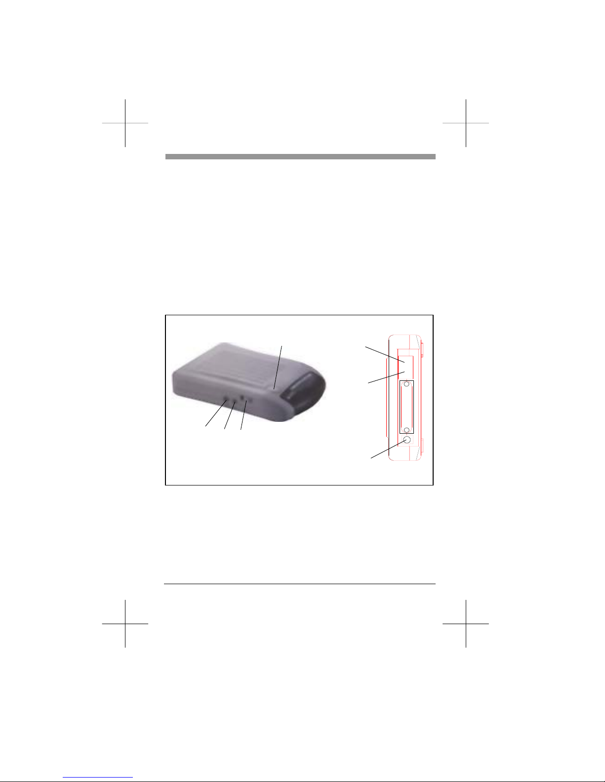
The Rear Panel and the Connectors __________________________
PHONE :Accepts a telephone set connected parallel to your modem.
LINE :Accepts the RJ-11 cable that links your modem to a
telephone line or to a 2-wire leased-line.
RS-232 :Accepts the serial cable that is connected between your
modem and your computer.
12VAC :Accepts the power adaptor that comes with your modem.
Power Adaptor
Power Switch
To Serial Port on
Your Computer
Connect to
Telephone Line
Connect to
Telephone Set
VR
MIC
SPK
The Serial Port and the RS-232 Cable_________________________
To use this modem, it will require an RS-232 serial port on your
computer. If your do not have it, you need to have one.
It is better to select a serial port card that uses a high-speed 16550
UART chip. A card with an ordinary UART chip handles transmissions
at a maximum speed around 38,400bps. In case the data compression of
Page:2
Page 3

your modem is active, it may perform at an exceeding speed and an
ordinary serial port card may sometimes cause data loss.
You will also require an RS-232 cable to connect your modem with
computer. You will be Asked to buy a modem cable if you are a PC
user. The modem cable shall, at one end, have a DB25M (male)
connector that fits the female connector on the modem, and at the other
end a serial port connector that matches your computer.
Hardware Connection______________________________________
1) Make sure that both the modem and computer are turned off.
2) Use an RS-232 cable to connect the modem to a serial port on your
computer. Secure the connector screw on it.
) Verify the serial port number in which your modem is connected.
You must Write down the port number as you will need to specify
this number during software installation. As a general rule on PC
applications, the port COM1 is connected to a mouse, while COM2
is for a modem.
3) Use an RJ-11 cable to connect the LINE jack to the wall outlet of the
telephone line.
4) Connect a telephone set to the PHONE jack. You may leave this
jack disconnected if desired.
5) Make sure that the power adaptor that comes with your modem is of
a correct voltage that complies with your power source. Use the
adaptor to connect the power source to the 12VAC jack on the
modem.
Page:3
Page 4

Test the Power Connection__________________________________
You can turn on your modem by pushing the power switch button and
watch the front panel indicators. Depending on the setting of your
modem, the MR and other indicators should light up. If none is lit,
check the power connection for the modem.
Test the Telephone Line Connection __________________________
Once a telephone set is connected, you may test the line quality and
connections by lifting the telephone handset, listening for a clear dial
tone, and making several telephone calls. The calls shoud go through
well and the sound loud and clear. Otherwise, the line may be poor or
have a faulty connection.
Data Communications Software Packages _____________________
Your modem follows the industrial standard in the modem command
set. As a result, most of the popular communications software packages
off-the-shelf will work with it. You should select a software package
according to your application requirement.
Most popular communications software are provided with the
configuration named Initial-String or Dialing-Prefix. It is wise to check,
one by one, the commands in this string as they will be sent to
determine the modem characteristics each time prior to dialing.
Fax Communications Software Packages ______________________
Similar to data communication applications, you interact with the
modem through the fax communications software.
Your modem only supports Class 1 command set.
Error-Correction and Data Compression______________________
Your modem supports the industrial standards of MNP 5 and ITU-T
(formerly called CCITT) V.42bis for error-correction and data
compression (ECDC). Both standards are capable of error-correction as
well. The modem will re-transmit a faulty data block when an error is
detected while receiving.
Page:4
Page 5

The ITU-T V.42bis can perform data compression at a rate up to four
times, depending on the format of data. That is, the throughput can be
reach as high as 57,600 bits per second when you are on-line at 14,400
bps.
The MNP 5 was popular before V.42bis was born. It can reach a
compression rate of two times, that is around half of what V.42bis can
do.
To enjoy the effectiveness of ECDC, both modems on-line should
exercise the same ECDC standard. You should always set your modem
to V.42bis auto-reliable mode by command \N3, which will
automatically negotiate with the remote modem for an available ECDC
standard.
Controlling the Modem Speaker _____________________________
In the factory, your modem speaker is preset in to medium volume and
turned on when the carrier from the remote modem is detected. You
may issue the commands L and M, with an appropriate parameter
following it, to control the volume, or turn on the speaker.
Page:5
Page 6

__________ The Modem Commands _________
Prefix, Repeat and Escape Commands ________________________
AT Attention. Precede all command lines except A/ and +++
A/ Re-execute the last command in command buffer
+++ Escape characters, requires guard time before and after
Dial Commands and Dial Modifiers __________________________
D Originate a call
S=n Dial the n
th
stored number
T Touch tone dialing
P Pulse dialing
R Dial in answer mode
W Wait for second dial tone
L Re-Dial the last valid telephone
number
, Pause
! Flash
; Return to command state
Operation Commands______________________________________
A Answer incoming call
B0 CCITT or ITU-T compatibility
B1 Bell protocol only
E0 Disable command echo
E1 Enable echo command
characters
H0 Hang up the connection
(on-hook)
H1 Go off-hook to make a call
I0 Reports product code
I1 Calculates the ROM checksum
I3 Reports firmware version
L0 Low volume
L1 Low volume
L2 Medium volume
L3 High volume
M0 Speaker off at all times
M1 Speaker on until CD detected
M2 Speaker always on
N0 Fixed data rate follow *N
command
N1 Enable adaptive data rate
O0 Return to data-link without
retrain
O1 Return to data-link with retrain
Q0 Modem se nds r e sponse codes
Q1 Do not send response codes
Sr? Display the value in register r
Sr=n Set register r to a value n
V0 Display response codes in digit
form
V1 Display response codes in
words
W0 Disable V.42 response codes,
display DTE speed
W1 Enable V.42 response codes,
Page:6
Page 7

display DCE speed
W2 Disable V.42 response codes,
display DCE speed
X0 Enable basic response codes
0-4
X1 Do not detect dial tone and
busy signal
X2 Include dial tone detection
response
X3 Include busy detection
response
X4 Enable all response codes
Y0 Do Not send (and ignore)
break signal
Y1 Send break signal for 4
seconds before disconnect
Z0 Reset modem with SCP0
Z1 Reset modem with SCP1
&C0 Turn CD signal to always on
&C1 CD on at remote carrier
detected
&D0 Alone with any of following
&Q0, &Q5, &Q6 then, DTR is
not functional.
Alone with any of following
&Q1, &Q4 then DTR drop
causes the modem hang up,
Auto-answer is not affected.
Alone with any of following
&Q2, &Q3 DTR drop causes
the modem to hang up,
Auto-Answer is inhibited
&D1 Alone with any of following
&Q0, &Q1, &Q4, &Q5, &Q6
DTR drop is interpreted by the
modem as if the asynchronous
escape sequence had been
entered. the modem return to
asynchronous command state
without disconnecting.
Alone with any of following
&Q2, &Q3 DTR drop causes
the modem to hang up.
Auto-Answer is inhibited.
&D2 Alone with any of following
&Q0 through %Q6 then,
DTR drop causes the modem
to hang up Auto-Answer is
inhang.
&D3 Alone with any of following
&Q0, &Q1, &Q4, &Q5, &Q6
DTR drop causes the modem to
perform a softreset as if the z
command were received. The &
Y setting determines which
profile is loaded.
Alone with any of following
&Q2, &Q3 DTR drop causes
the modem to hang up
Auto-Answer is inhibited.
&F0 Restore factory default profile
FDP0 (as ECDC modem)
&F1 Restore factory default profile
FDP1 (as non-ECDC modem)
&G0 Disable guard tone
&G1 Disable guard tone (default for
us models)
&G2 Enable 1800 Hz guard tone
&Ln Leased line dail line operation
&L0 Dial-Up line operation
&G2 Leased line operation
&K0 Disable flow control
Page:7
Page 8

&K3 RTS/CTS flow control
&K4 XON/OFF flow control
&K5 Unidirectional XON/OFF
&K6 RTS/CTS, XON/XOFF flow
control
&M0 Set modem for async
operation
&M1 Enter sync mode after async
dialing
&M2 Sync terminal support. Modem
dials a stored number and
enters sync mode when DTR
off-to-on
&M3 Dial manually while DTR off,
handshake proceeds when DTR
off-to-on
&P0 M/B ratio 39/61(USA)
&P1 M/B ratio 33/67(UK, Hong
Kong)
&P2 M/B ratio 39/61 at 20 pulses
&P3 M/B ratio 33/67 at 20 pulses
&Q0 See & M0
&Q1 See & M1
&Q2 See & M2
&Q3 See & M3
&Q4 Selects Auto Sync operation.
When used in conjunction with
the Hayes synchronous
interface (HCI)capability in the
DTE. Provides synchronous
communication capability from
an asynchronous terminal
&Q5 The modem will try to
negotiate an error-corrected
link
&Q6 Select asynchronous operation
in normal mode
&R0 Modem turns CTS on when
detects RTS from the local
computer
&R1 Ignore RTS. Modem turns CTS
on when ready to receive
synchronously
&S0 Modem forces DSR always on
&S1 Set DSR to follow RS-232 spec
&T0 Terminates test in progress
&T1 Initiates local analog loopback,
V.34 Loop3, Sets S16 bit0. If
aconnect exists when this
command is issued, the modem
hangsup, The connect xxxx
message is displayed upon the
start of the test.
&T5 Disable digital loopback
acknowledgment for remote
request.
&T8 Initiates local analog loopback,
V.34 Loop3, with selftest.
&V Display modem profiles and
numbers
&W0 Write ACP to SCP0
&W1 Write ACP to SCP1
&X0 Select internal clock
&X1 Select external clock
&X2 Select slave clock
&Y0 Designate SCP0 as the active
SCP
&Y1 Designate SCP1 as the active
SCP
&Zn= Save up to three numbers to
NVRAM. Use DS=n to dial the
stored number
Page:8
Page 9

Note: &Q,&M: for Sync mode only
V.42bis and MNP Commands _______________________________
\A0 MNP block size 64 characters
\A1 MNP block size 128
characters
\A2 MNP block size 192
characters
\A3 MNP block size 256
characters
\Bn Send n/10 seconds of line
break to the modem (n = 0 ~ 9,
default 3)
\K0 Enter command mode, do not
send a break signal to remote
(To send a break after use the
\B command)
\K1 Clear data buffer and send a
break
\K2 Same as \K0
\K3 Immediately send a break
\K4 Same as \K0
\K5 Send a break in sequence
with any data received from
the port
\N0 Set modem to normal mode
\N1 Set modem to direct mode
\N2 Set modem to MNP reliable
mode
\N3 Set to MNP/V.42
auto-reliable mode
\N4 V.42 reliable with phase
detection
\V0 Connect messages are
controlled by the command
settings X, W, and S95.
\V1 Connect message displayed in
the single line format
described below subject to the
command settings V (Verbose)
and Q(Quiet). In
Non-Verbose mode(V0),
single line connect messages
are disabled and a single
numeric result code is
generated for CONNECT
DTE.
%C0 Disable data compression
%C1 Enable MNP5 data
compression negotiation
%C2 Enable V.42bis data
compression
%C3 Enable both V.42bis and
MNP5 data compression
(default)
%E0 Disable auto-retrain
%E1 Enable auto-retrain
%E2 Enable fallback/fall forward
Page:9
Page 10

Voice Commands for Rockwell Chip Set _____________________
The Voice Command
Command Function
A Answering in Voice/Audio Mode
D Dial command in Voice/Audio Mode
H Hang up in Voice/Audio Mode
Z Reset from Voice/Audio Mode
#BDR=n Select baud rate (turn off autobaud) 0<n<48
#CID=n Enable Caller ID detection and select reporting format n=0~2
#CLS=n Select data, fax, or Voice/Audio n=0,1,2,8
#MDL? Identify model
#MFR? Identify manufacturer
#REV? Identify revision level
#TL Audio output transmit level
#VBQ? Query buffer size
#VBS=n Bits per sample (ADPCM or PCM) n=2,4,8
#VBT=n Beep tone timer n =0~40 (0-4 seconds)
#VCI? Identify compression method (ADPCM)
#VLS=n Voice line select (ADPCM or PCM) n=@~9
#VRA Ringback goes away timer (originate)
#VRN Ringback never came timer (originate)
#VRX Voice Receive Mode (ADPCM or PCM)
#VSD Enable silence deletion (voice receive, ADPCM)
#VSK=n Buffer skid setting n=255
#VSP Silence detection period (voice receive, ADPCM)
#VSR Sampling rate selection (ADPCM or PCM)
#VSS Silence detection tuner (voice receive, ADPCM)
#VTD DTMF tone reporting capability
#VTM Enable timing mark placement
#VTS Generate tone signals
#VTX Voice transmit mode (ADPCM or PCM)
Page: 10
Page 11

Fax Class I Commands___________________________________
Command Function
Service Class ID
+FCLASS= Service Class
Fax Class 1 Commands
+FAE=n Data/Fax auto Answer
+FTS=n Stop Transmission and Wait
+FRS=n Receive Silence
+FTM=n Transmit Data
+FRM=n Receive Data
+FTH=n Transmit Data with HDLC Framing
+FRH=n Receive Data with HDLC Framing
Page: 11
Page 12

Fax Class II Commands__________________________________
Command Function
+FCLASS=n Service class
+FAA=n Adaptive answer
+FAXERR Fax error value
+FBOR Phase C data bit order
+FBUF? Buffer size (read only)
+FCFR Indicate confirmation to receive
+FCLASS= Service class
+FCON Facsimile connection response
+FCIG Set the polled station identification
+FCIG: Report the polled station idendification
+FCR Capability to receive
+FCR= Capability to receive
+FCSI: Report the called station ID
+FDCC= DCE capabilities parameters
+FDCS: Report current session
+FDCS= Current session results
+FDIS: Report remote capabilities
+FDIS= Current sessions parameters
+FDR Begin or continue phase C receive data
+FDT= Data transmission
+FDTC: Report the polled station capabilities
+FET: Post page message response
+FET=N Transmit page punctuation
+FHNG Call terminati on with stat us
+FK Session termination
+FLID= Local ID string
+FLPL Document for polling
+FMDL? Identify model
+FMFR? Identify manufacturer
+FPHCTO Phase C time out
+FPOLL Indicates polling request
+FPTS: Page transfer status
+FPTS= Page
+FREV? Identify revision
+FSPL Enable polling
+FTSI: Report the transmit station ID
Page: 12
Page 13

S-Register Summary _______________________________________
Register Range Units Default Function
S0 0-255 Rings 0 Rings to Auto-Answer
S1 0-255 Rings 0 Rings Counter
S2 0-255 ASCII 43 Escape character
S3 0-127 ASCII 13 Carriage return character
S4 0-127 ASCII 10 Line Feed Character
S5 0-255 ASCII 8 Backspace character
S6 2-255 s 2 Wait Time for Dial Tone
S7 1-255 s 50 Wait Time for Carrier
S8 0-255 s 2 Pause Time for Dial Delay Modifier
S9 1-255 0.1s 6 Carrier Detect Response Time
S10 1-255 0.1s 14 Carrier Loss Disconnect Time
S11 50-255 0.001s 95 DTMF Tone Duration
S12 0-255 0.02s 50 Escape Prompt Delay
S13 - - - Reserved
S14 - - 138(8Ah) General Bit Mapped Options Status
S15 - - - Reserved
S16 - - 0 Test Mode Bit Mapped Options
Status(&T)
S17 - - - Reserved
S18 0.255 s 0 Test Timer
S19 - - 0 AutoSync Options
S20 0-255 - 0 AutoSync HDLC Address or BSC
Sync Character
S21 - - 52(34h) V.24/General Bit Mapped Options
Status
S22 - - 117(75h) Speaker/Results bit Mapped Options
Status
S23 - - 62(3Dh) General Bit Mapped Options Status
S24 0-255 s 0 Sleep Inactivity Timer
S25 0-255 s or 0.01s 5 Delay to DTR Off
S26 0-255 0.01s 1 RTS-to-CTS Delay
S27 - - 73(49h) General Bit Mapped Options Status
S28 - - 0 General Bit Mapped Options Status
S29 0-255 10ms 70 Flash Dial Modifier Time
S30 0-255 10s 0 Disconnect Inactivity Timer
Page: 13
Page 14

Page: 14
Register Range Units Default Function
S31 - - 194(C2h) General Bit Mapped Options Status
S32 0-255 ASCII 17(11h) XON Character
S33 0-255 ASCII 19(13h) XOFF Character
S34-S35 - - - Reserved
S36 - - 7 LAPM Failure Control
S37 - - 0 Line Connection Speed
S38 0-255 s 20 Delay Before Forced Hang-up
S39 - - 3 Flow Control Bit Mapped Options
Status
S40 - - 104(68h) General Bit Mapped Options Status
S41 - - 195(C3h) General Bit Mapped Options Status
S42-S45 - - - Reserved
S46 - - 138 Data Compression Control
S48 - - 7 V.42 Negotiation Control
S82 - - 128(40h) LAPM Break Control
S86 0-255 - - Call Failure Reason Code
S91 0-15 dBm 10(country
dependent)
PSTN Transmit Attenuation Level
S92 0-15 dBm 10(country
dependent)
Fax Transmit Attenuation Level
S95 - - 0 Result Code Messages Control
♦ Register value may be stored in one of two user profiles with the &W command.
Page 15

Result Codes___________________________________________
n Value in ATXn Command
0 1 2 3 4
0 OK x x x x x Note 2
1 Connect x x x x x
2 Ring x x x x x
3 No Carrier x x x x x
4 Error x x x x x
5 Connect 1200 1 x x x x
6 No dial tone 3 3 x x x
7 Busy 3 3 3 x x
8 No Answer x x x x x
9 Connect 600 1 x x x x
10 Connect 2400 1 x x x x
11 Connect 4800 1 x x x x
12 Connect 9600 1 x x x x
13 Connect 7200 1 x x x x
14 Connect 12000 1 x x x x
15 Connect 14400 1 x x x x
16 Connect 19200 1 x x x x
17 Connect 38400 1 x x x x
18 Connect 57600 1 x x x x
19 Connect 115200 1 x x x x
20 Connect 230400 x x x x x Note 2
22 Connect 75TX/1200RX 1 x x x x
23 Connect 1200TX/75RX 1 x x x x
24 Delayed 4 4 4 4 x
32 Blacklisted 4 4 4 4 x
33 Fax x x x x x
35 Data x x x x x
40 Carrier 300 x x x x x
44 Carrier 1200/75 x x x x x
45 Carrier 75/1200 x x x x x
46 Carrier 1200 x x x x x
47 Carrier 2400 x x x x x
48 Carrier 4800 x x x x x
49 Carrier 7200 x x x x x
50 Carrier 9600 x x x x x
51 Carrier 12000 x x x x x
52 Carrier 14400 x x x x x
Short Form Long Form Notes
Page: 15
Page 16

n Value in ATXn Command
Short Form
0 1 2 3 4
Notes Long Form
53 Carrier 16800 x x x x x
54 Carrier 19200 x x x x x
55 Carrier 21600 x x x x x
56 Carrier 24000 x x x x x
57 Carrier 26400 x x x x x
58 Carrier 28800 x x x x x
59 Connect 16800 1 x x x x
61 Connect 21600 1 x x x x
62 Connect 24000 1 x x x x
63 Connect 26400 1 x x x x
64 Connect 28800 1 x x x x
66 Compression: Class 5 x x x x x
67 Compression: V.42bis x x x x x
69 Compression: None x x x x x
70 Protocol: None x x x x x
77 Protocol: LAPM x x x x x
78 Carrier 31200 x x x x x
79 Carrier 33600 x x x x x
80 Protocol: ALT x x x x x
81 Protocol: ALT-Cellular x x x x x
84 Connect 33600 1 x x x x
91 Connect 31200 1 x x x x
150 Carrier 32000 x x x x x Note 2
151 Carrier 34000 x x x x x Note 2
152 Carrier 36000 x x x x x Note 2
153 Carrier 38000 x x x x x Note 2
154 Carrier 40000 x x x x x Note 2
155 Carrier 42000 x x x x x Note 2
156 Carrier 44000 x x x x x Note 2
157 Carrier 46000 x x x x x Note 2
158 Carrier 48000 x x x x x Note 2
159 Carrier 50000 x x x x x Note 2
160 Carrier 52000 x x x x x Note 2
161 Carrier 52000 x x x x x Note 2
162 Carrier 56000 x x x x x Note 2
165 Connect 32000 x x x x x Note 2
166 Connect 34000 x x x x x Note 2
167 Connect 36000 x x x x x Note 2
168 Connect 38000 x x x x x Note 2
169 Connect 40000 x x x x x Note 2
170 Connect 42000 x x x x x Note 2
Page: 16
Page 17

n Value in ATXn Command
Short Form
0 1 2 3 4
Notes Long Form
171 Connect 44000 x x x x x Note 2
172 Connect 46000 x x x x x Note 2
173 Connect 48000 x x x x x Note 2
174 Connect 50000 x x x x x Note 2
175 Connect 52000 x x x x x Note 2
176 Connect 54000 x x x x x Note 2
177 Connect 56000 x x x x x Note 2
+F4 +FCERROR x x x x x
Notes:
An “x” in a column indicates that the message (either the long form if verbose, or the
value only for short form) will be generated when that particular value of “n” (shown at
the top of the column) has been selected by the use of ATXn. If the (verbose or short
form) will be output for that X option.
Page: 17
Page 18

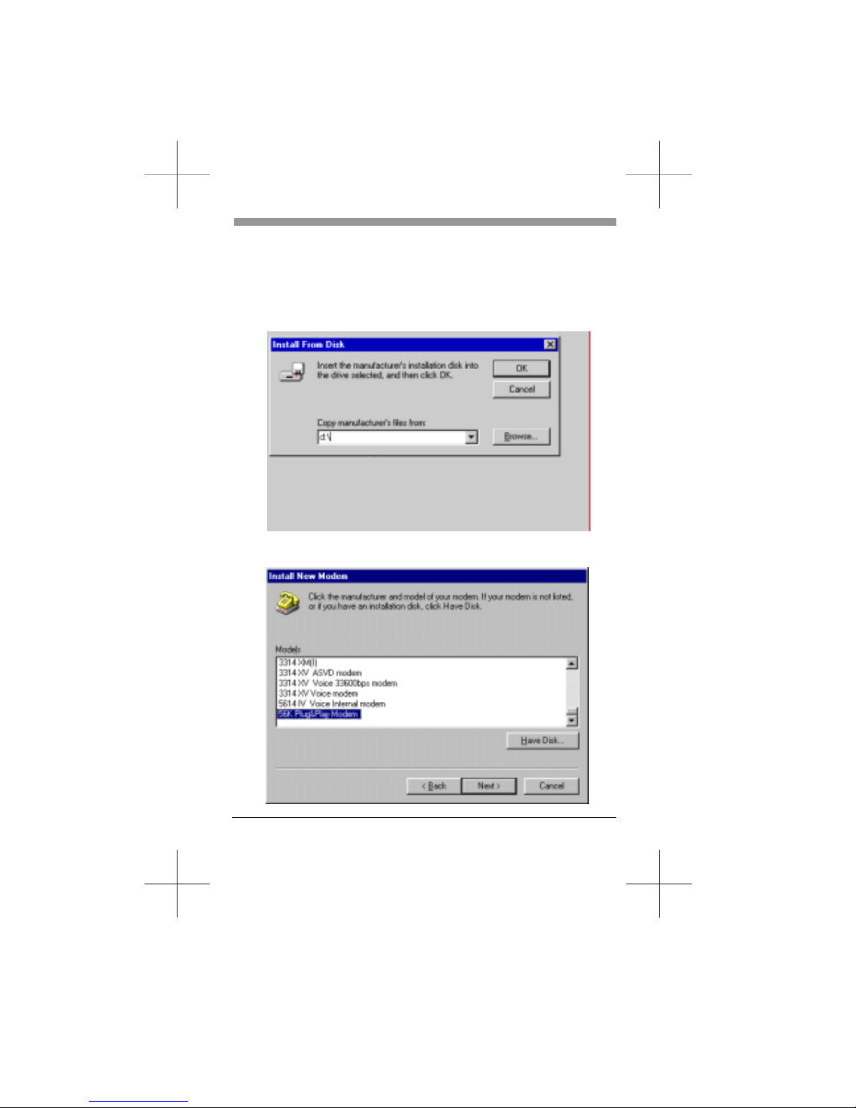
_ Installation of Modem Driver in Windows 95/98 ____
(1) Turn on computer. Move mouse to “Start” at left hand side, enter
“Setting-s” and select “Control panel”.
(2) Under “Control Panel” select “Modems”. (or Move mouse to “My
compu-ter” at right hand side, enter “Control panel and Modems”.)
Page: 18
Page 19

(3)
In Install New Modem, please tick “Don‘t detect my modem; I will select
it from a lost”, and then go to next step.
(4) Because the modem is not listed, you click “Have Disk” for other modem
models.
Page: 19
Page 20
(5) Insert the installation disk into the driver selected, click “Browse”, select
one of the inf files (Dtxmodem.inf for discovery products; Logmodem.inf
for DataSystem products), and then click “OK”.
(6) Click the manufacturer and model of your modem, and then go to next
step.
Page: 20
Page 21

(7) Select the port to use with this modem, for example COM2, and then click
“Next”.
(8) Your modem has been set up successfully. Click “Finish”.
Page: 21
Page 22

Page: 22
(9) Select the modem you have, and then click “OK”.
 Loading...