

Page 1

Chapter 1
UNPACKING AND INSTALLATION
This chapter describes the procedures for unpacking and installing
your modem. Chapter 1 is designed to have normal PC users on-line
quickly.
1.1 Unpacking the Modem
The complete Discovery LCD Fax/Audio modem package includes:
1. Discovery LCD Faxmodem unit
2. User's manual
3. Power supply unit
4. Data and fax communication software
5. RJ-11 to RJ-11 cable
6. RJ-45 to Y terminal cable
7. 6 by 2 terminal block
Carefully inspect the contents of the package for shipping damage. If
there is damage, immediately repack the modem in the original
packing material and contact your dealer.
1.2 Modem Front Panel and LED Indicators
Located on the modem front panel are the LCD, LCD configuration
buttons, LCD Panel Lock switch, the Voice/Data switch, and the LED
indicators. The modem LCD, LCD configuration buttons, Panel Lock
switch and Voice/Data switch are described in Chapter 2. The LED
indicators display current modem operation and status, as explained
below:
MR Modem Ready
Lit when modem is turned on. Flashes when modem is in test
mode.
TR Terminal Ready
Lit when the computer or terminal is ready.
Page: 1
Page 2

RTS Request To Send
Lit when local computer (DTE) requests to send data to local
modem for transmission.
CTS Clear To Send
Lit when local modem is ready to receive data from local
computer (DTE) for transmission.
AA Auto Answer
Lit when modem is set for auto-answer. Flashes when
incoming rings are detected.
RL Reliable Link
Lit when error correction mode is enabled. Flashes when an
error is detected.
RD Receive Data
Flashes when modem is receiving data from a remote modem
or when sending data to the local computer.
SD Send Data
Flashes when the modem is sending data to a remote modem or
when receiving data from the local computer.
CD Carrier Detected
Lit when a remote modem carrier is detected.
OH Off Hook
Lit when the modem is using the telephone line (off hook). Off
when the modem is not using the line (on hook).
1.3 Modem Rear Panel
Located on the modem rear panel are the power switch, power socket,
volume control, RS-232 connector, and two modular jacks, as shown
in the schematic.
The power socket is labelled 9V or 12V AC (optional) and corresponds
with the power supply unit packaged with your modem. Never use a
non-specified power supply unit, as it might damage your modem.
To turn on the modem, toggle the power switch to ON. Likewise, to
turn off the modem, toggle the power switch to OFF. Always turn your
computer on prior to turning on your modem and turn off your modem
prior to turning off your computer.
Page: 2
Page 3

The RS-232 connector on the modem rear panel corresponds to the
RS-232 cable and connects the local computer to the modem. It is a
DB25F (female) and a RS-232 cable in pin assignment and electronic
standards. See the following section for more information about the
RS-232 cable.
Two modular jacks are also on the modem rear panel (RJ-11 and RJ-
45). The jack labelled LINE is for an incoming telephone line (RJ-11)
and the jack labeled PHONE LEASED is for a telephone set or an
incoming leased line(RJ-45). If you do not wish to use a telephone set
with your modem, leave the PHONE jack unconnected.
1.4 Serial Port and RS-232 Cable
Fig 1-1 Modem Rear Panel
ON
VOL
9V.AC
RS-232
PHONE
LEASE
LINE
Your computer requires an industry standard RS-232 serial port in
order to use this modem or any other external modem. If you do not
have a standard RS-232 serial port, consult your dealer to acquire a
RS-232 interface card for your computer.
You also need a serial cable between your modem and your computer's
serial port. A proper cable for your modem includes:
Page: 3
Page 4

1) DB25M (male) connector at one end to match the modem connector.
2) A connector that corresponds to your computer's serial port at the
other end. For PC users, a standard serial port card has either a
DB25M or DB9M connector, and your cable must possess one of
these two connectors.
3) A correct pin-to-pin cable connection. Your modem complies
with industry standard pin assignments, and most standard
modem cables should fit. However, refer to Appendix B in this
manual for more information concerning the pin assignment for
your modem connector.
If you have any problem acquiring the appropriate RS-232 cable,
consult your modem distributor or computer dealer.
1.5 Telephone Line Test and Phone Cable
Telephone line quality significantly affects the reliability of data
communications. Make sure that both the telephone system and
telephone line are in good order before the modem is connected.
First, test the line condition by lifting the telephone handset, listening
for a clear dial tone, and then placing a few calls. If the calls do not go
through well or are not loud and clear, you may have a poor quality
telephone line. If this is the case, find a better quality line for your
modem to ensure reliable data communications.
Connect your modem directly to an outside telephone line. Do not
connect the modem to a private branch exchange (PBX) telephone
system unless the system is proven to perform well in data
transmission applications.
You need a phone cable to connect the incoming telephone line to the
modem. The cable must have an RJ-11 plug at one end and a connector
which fits the telephone line wall outlet at the other end. If the cable
included with your modem does not fit your wall outlet, acquire an
appropriate cable.
1.6 Modem Installation
Page: 4
Page 5

The distance between the computer and modem is determined by the
length of the RS-232 cable. However, a RS-232 cable should not be
longer than fifty feet, as signal distortion and interference might occur.
A suitable location for your modem includes:
1) A reliable AC power source and a good quality telephone outlet
that are not too far away from the computer.
2) A location where the LED indicators and LCD are easy to
monitor, and where the LCD buttons on the front panel and the
power switch on the rear panel are easy to reach.
Once you have chosen a proper location for your modem, follow the
procedures below to connect the hardware:
1) Make sure both the modem and the computer are turned off.
2) Connect the modem to the computer by plugging the DB-25M
end of the RS-232 cable into the modem and plugging the other
end of the cable into your computer's serial port. Secure all the
connector screws.
NOTE:
Verify and write down which serial port (COM1 to COM4)
connects your modem to the computer, as the port number is
required during communications software installation. Refer to
the manual for your serial interface card or your terminal to find
out how the port is set or configured.
3) Using an appropriate cable, connect the modem to the incoming
telephone line through the LINE jack on the modem rear panel.
Be sure you tested the line quality as described in the previous
section.
4) Insert the cable-plug end of the power adaptor into the power jack
marked AC9V or AC12V (optional) on the modem rear panel,
and then plug the adaptor into a reliable power outlet. Be sure to
only use the adaptor that came with your modem. Also check that
the power source voltage is correct before plugging in the adaptor.
1.7 Communication Software Installation
Page: 5
Page 6

Since your modem has a standard modem command set, most popular
communication software packages are compatible. To install the
software, turn on your computer and modem and then follow the
software manual instructions.
Unfortunately, we are unable to describe software configuration
procedures in detail, as the procedures vary with each software
package, computer, and application. Refer to the software manual with
your modem package for more information. If you experience any
difficulty regarding use of the software package, please contact the
software publisher or us.
However, pay particular attention to the following parameter settings,
as an unsuccessful modem installation is probably due to an incorrect
setting.
1) The serial port number is set from COM1 to COM4.
2) The communications protocol is either ITU-T or Bell.
3) The data is formatted correctly, including: data bit, parity, and
stop bit (8N1 or another valid format).
A serial port can accept only one peripheral device, and vice-versa.
The serial port number specified in the communications software must
be consistent with the computer's serial port to which the modem is
actually connected.
The selection of a serial port is done on the serial port card. The ports
are usually denoted as COM1 to COM4. Refer to the serial port card's
manual for details.
In order to communicate successfully, the protocol and data format of
the two on-line modems must be the same. For example, if the bulletin
board you are going to dial supports ITU-T standard (8 data bits, no
parity, 1 stop bit), you should specify exactly the same. Otherwise, the
connection will not be established or the data received will be
unreadable (garbled).
1.8 Software Configuration Tips
Many popular communications software packages allow users to
Page: 6
Page 7

specify a command string which is sent to the modem prior to a dialing
session. This string is usually called the Dialing Prefix or Dialing
String, and it instructs the modem prior to dialing and going on-line.
Listed below are common commands which are helpful for setting the
software Dialing Prefix/Dialing String.
ATS0=3 Instructs the modem to auto answer an incoming
call on the third ring by setting register S0 to 3.
ATX4DT9W Instructs the modem to tone dial the number 9 and
hold it until a dial tone is detected. This string also
selects the X4 response set.
ATS6=10DP Instructs the modem to wait for 10 seconds and
then use pulse dial the call.
ATM2L3DT The modem monitoring speaker is always on, with
high volume, and tone dials the call.
ATB0DT Instructs the modem to use ITU-T protocol to
establish a connection with the remote modem and
tone dial the call.
AT&P1DP Pulse dials with a make/break ratio of 33/67 (for
most European countries).
AT&P0DP Pulse dials with a make/break ratio of 39/61 (for
USA).
AT\N1 Instructs the modem to operate in direct mode and
function as an ordinary non-MNP/V42 modem.
Configuring the modem for ECDC operation with error correction and
data compression enabled will result in better performance and higher
speeds from your modem.
Page: 7
Page 8

The following two examples set the modem to auto reliable mode, use
CTS/RTS flow control, and enable ECDC extended response code sets
without baud rate adjustment:
AT\J0\N3\Q3\V4%C1 Error correction and Data compressinare
both enabled.
AT\J0\N3\Q3\V4%C0 Error correction enabled but Data
compression disabled.
For general PC users in normal applications, the recommended Dialing
Prefix is:
AT\J0\N3\Q3\V4%C1
To set the modem to auto reliable mode with a carriage return (ASCII
13) as the fallback character, the Dialing Prefix is:
AT\C2\N3\Q3\V4%A13
To set the modem to operate in MNP reliable mode and hang up when
a MNP reliable link cannot be established, the Dialing Prefixes are:
AT\J0\N2\Q3\V0%C1 Data compression enabled.
AT\J0\N2\Q3\V0%C0 Data compression disabled.
1.9 Getting Started
Now you are ready to dial a bulletin board, data base, or remote
computer, and your modem will automatically establish a connection.
As soon as a connection is established, you can:
1. Read or send electronic mail.
2. View the most up-to-date news or information.
3. Upload or download computer programs.
4. Transmit or receive text messages or spread sheet data.
5. Play interactive games with remote uses.
Or, you can establish whatever kind of on-line data communication
link you wish.
Page: 8
Page 9

Chapter 2
LCD OPERATION AND FUNCTIONS
This chapter describes the operation and functions of the modem LCD
control panel. Instructions for LCD control panel operation as well as
the LCD main menu, directories, subdirectories, and their contents are
provided. This chapter is designed to minimize the time required to
learn the LCD control panel operation and get the modem on-line.
2.1 LCD Control Panel Operation
The LCD control panel has four configuration buttons: ESC (escape),
Left Arrow, Right Arrow, and ENTER. These configuration buttons
are used to enter, view, configure, and reconfigure the modem main
menu, directories, subdirectories, and their contents.
The modem LCD main menu is divided into four areas: STATUS,
SETUP, PROFILE, and EXECUTE. Moreover, the four main menu
areas contain directories, and some contain subdirectories as well.
Follow the directions below to enter the LCD main menu, directories,
subdirectories, and their contents.
1. Using the power switch located on the modem rear panel, turn the
modem on. After the power has been turned on, the LCD displays:
POWER ON
INITIAL
Then the modem immediately displays the current specified
modem configuration status. For example, the LCD might display:
AUTO ASY V.42bis
DL ORI IDLE
This means that the modem is currently in auto, asynchronous,
V.42bis mode, on a dedicated line, being the originating modem,
and currently idle (no connection).
Page: 9
Page 10

You can press the ESC button to view factory EPROM version,
LCD will display such as:
DATATRONICS
341-008-137
2. Press the ENTER button to view the LCD Main Menu. The LCD
will display:
<MAIN MENU>
STATUS
Remember that STATUS is the first possible directory users can
view. However, you can not configure the contents of STATUS.
3. Pressing either the left or right arrow buttons on the LCD control
panel allows users to choose either the STATUS, SETUP,
PROFILE or EXECUTE Directories.
4. After choosing a directory, first press ENTER, then use LIFT,
RIGHT and ENTER button to view either that directory's contents,
subdirectory, or both. Continue to use the LEFT, RIGHT or
ENTER button to choose directory contents or subdirectory
contents for configuration. Once users are in a particular directory
or subdirectory and viewing its contents, pressing the ENTER
button will assign configurations to the modem for operation. At
this point users should be able to hear a "beep" from the modem
and see an asterisk (*) next to the configuration, representing that
the configuration is now enabled.
5. Once you enter any particular directory, subdirectory, or the
contents of either, use the left and right arrow buttons to begin
modem configuration. In general, if the contents of any directory
or subdirectory are standard (not modifiable by users and
permanently entered in the modems NVRAM), use either the left
or right arrow buttons to go forward or backward to view the
contents before pressing ENTER and enabling a configuration. In
contrast, if the contents of a directory or subdirectory include user
modifiable configurations, such as passwords, telephone numbers,
speeds, or times, which may amount to a long string of characters,
modem configuration is slightly different. Pressing the right
Page: 10
Page 11

arrow button allows users to move along the character string to
any particular point in the sting. Pressing the left arrow button
then allows users to select the possible characters for that point in
the string. When all the characters in the particular string are
shown on the LCD as desired, pressing ENTER will enable the
configuration for use.
6. Pressing the ESCAPE button allows you to exit any particular
directory, subdirectory or the contents of either. Continuing to
press the ESCAPE button will retrace your steps and eventually
bring users back to the main menu and then to the modem's
current operational status.
7. Now you are ready to begin modem operation and configuration.
2.2 LCD Panel Lock Switch
The Panel Lock switch located on the modem control panel secures the
LCD panel buttons from unauthorized use and protects your
communications and configurations from interruption due to accidental
panel button operation.
To use the Panel Lock switch, press and hold the Panel Lock switch
and the LCD will display PANEL LOCKING with a cursor crossing
the LCD below the message, until the panel is locked. The LCD will
then display DATATRONICS PANEL LOCKED. Remove your
finger from the Panel Lock switch and the LCD displays the original
status message.
To unlock the panel, press and hold the Panel Lock switch and the
LCD will display PANEL UNLOCKING with a cursor crossing the
LCD below the message, until the panel is unlocked. The LCD will
then display DATATRONICS PANEL UNLOCKED. Remove your
finger from the Panel Lock switch and the LCD displays the original
status message.
Page: 11
Page 12

2.3 Voice/Data Switch
The Voice/Data switch on the modem control panel lets you switch
between data link and voice link while on-line, without breaking online status. In data link you can transmit or receive data through the
modem. In voice link you can talk to the other party.
To use the Voice/Data feature, both modems need a telephone set
connection. To switch a call from data link to voice link:
1. Request a talk link by typing a message on your keyboard such as
“Request for voice link, pick up your phone.”
2. Lift your telephone handset and press your modem‘s Voice/Data
switch to VOICE.
You can now talk to the other party on the telephone connected to your
modem as soon as they pick up their telephone handset connected to
their modem.
As soon as the link is switched to talk link, your modem will issue a
NO CARRIER message on the screen and the connection is bypassed
to the telephone handset connected to your modem. If the handset is
not picked up before flipping the switch to VOICE, the call is
disconnected.
When the conversation ends, follow the procedures below to resume
data link:
1. Inform the other party of your request to resume data link.
2. Press the Voice/Data switch to DATA and hang up your
telephone handset.
3. Have the other party press their Voice/Data switch to DATA and
hang up their handset upon hearing a high-pitched tone from their
modem.
If the remote modem does not have the same Voice/Data function as
your modem, the other party should issue command ATX1D to force
their modem to go into dialing mode and then hang up their handset.
Page: 12
Page 13

You may also use the modem as an auto dialing device. First, instruct
the modem to dial the desired telephone number. When you hear the
remote party answer your call, pick up your telephone handset, press
the Voice/Data switch to VOICE and then talk to the other party.
2.4 Main Menu and Directories
The Modem Main Menu has four directories. The directories are:
STATUS, SETUP, PROFILE, and EXECUTE. Refer to the following
descriptions of the directories and their contents for moden status,
functions, and control. All modem commands and modem registers for
any particular setting are indicated by bold type.
2.5 STATUS Main Menu
STATUS in the Main Menu is set up to provide a quick reference for
the operation status of the modem.
QUALITY (line quality): GOOD, MEDIUM, BAD
S/N RATIO: xx dB
RX LEVEL: -xx dBm
TX LEVEL: -xx dBm
RETRAINS: xxxxx
RLSD LOSS: xxxxx
DTE: xxxxx xxx xx
TX&RX THROUGHPUT: xxxxxx xxxxxx
DISCONNECT MESSAGE: NONE, ATH DISC, DTR OFF,
VOICE/DATA DISC,
CARRIER
LOSS,NOANSWER,V42
FRAME ERROR, NO MATCH,
USER KEY ABORT
Page: 13
Page 14

2.6 SETUP Main Menu
SETUP in the Main Menu contains the following directories: DTE,
DCE, COMMAND, LINE, PROTOCOL, CALL BACK,REMOTE
ACCESS and MISC. SETUP in the Main Menu provides most of the
directories needed for setting and monitoring basic modem functions.
2.7 SETUP Main Menu: DTE Directory
The DTE directory contains the following settings:
DTE SPEED: AUTO, 110, 300, 600, 1200, 2400,
4800, 7200, 9600, 14400, 19200,
28800, 38400, 57600, 115200
DATA BITS: 7, 8
PARITY: NONE, SPACE, EVEN, ODD
STOP BIT: 1, 2
FLOW CONTROL (\Q): NONE, XON/XOFF, CTS ONLY,
RTS/CTS
DTR CONTROL (&D): IGNORE DTR, COMMAND
STATE, DISCONNECT, RESET
DTR DROP TIME (S25): xx 10ms
DTR RISE TIME: xx 10ms
RTS CONTROL (&R): CTS TRACK RTS, IGNORE RTS
RTS/CTS DELAY (S26): xx 10ms
DSR CONTROL (&S): FORCE ON, FOLLOW DTE
DCD CONTROL (&C): FORCE ON, TRACK CARRIER
Page: 14
Page 15

2.8 SETUP Main Menu: DCE Directory
The DCE directory contains the following settings:
DCE SPEED (%B): AUTO, 300, 1200, 2400, 4800, 7200,
9600, 12000, 14400, 16800,
19200, 21600, 24000, 26400, 28800
PROTOCOL TYPE (-V): V.34 AUTO, V.FC AUTO, V.32BIS
AUTO, V.34/V.FC/V.32BIS, V.FC/
V.32BIS, V.34 ONLY, V.FC ONLY,
V.32BIS ONLY
SYN MODE (&M): ASYN, SYN1, SYN2, SYN3
CNG TONE: DISABLE, ENABLE
TX CLOCK (&X): INTERNAL, FROM DTE, FROM
REMOTE
DCD ON TIME (S9): xxx 100ms
DCD OFF TIME (S10): xxx 100ms
GUARD TONE (&G): DISABLE, 550Hz, 1800Hz
RLSD LEVEL : -43/-48dBm, -33/-38dBm, -26/-31dBm,
-16/-21dBm
AUTO RETRAIN (%E): DISABLE, ENABLE, WITH SPEED
DISCONNECT (Y): NORMAL, LONG SPACE, CLEAR
DOWN
2.9 SETUP Main Menu: COMMAND Directory
The COMMAND directory contains the following settings:
MODE SELECT: AT, V25BIS, DUMB
DATA FORMAT: ASYNC, HDLC, BISYNC,
MONOSYNC
Page: 15
Page 16

DATA BITS: 5,6,7,8
PARITY: NONE, EVEN, ODD, SPACE
STOP BIT: 1, 2
COMMAND ECHO (E): ON, OFF
RESULT CODE (Q): ON, OFF
RESULT FORM (V): SHORT, LONG
ESCAPE CHAR (S2): xxx
ESCAPE GUARD (S12): xxx 20ms
CR CHAR (S3): xxx
LF CHAR (S4): xxx
BS CHAR (S5): xxx
2.10 SETUP Main Menu: LINE Directory
The LINE directory contains the following settings:
TYPE SELECT (&L): DIAL LINE, 2W LEASED, 4W
LEASED
DIAL METHOD(@Y) : NORMAL DIAL, DL SIMU LL, LL
BACKUP DL
BACKUP TIMER (S15): xxx min (1-255)
BACKUP TIMES (S13): xxx (0-225)
BACKUP RETRY (-B): xx (0-15)
RI OFF TIME: xx sec (0-15)
PULSE M/B (&P): US, UK
Page: 16
Page 17

2.11 SETUP Main Menu: PROTOCOL Directory
The PROTOCOL directory contains the following settings:
LINK MODE (\N): NORMAL,DIRECT MNP RELIABLE,
V42/MNP AUTO, V42 RELIABLE
COMPRESSION (%C): ON, OFF
MNP BLOCK (\A): 64, 128, 192, 256
SEND ADP/ODP: ON, OFF
BREAK CTL (\K): x (0-5)
DCE FLOW CTL (\G): ON, OFF
XON/XOFF PASS (\X): ON, OFF
CONNECT CODE (\V): DCE SPEED, DTE/EC, DCE/EC,
DTE EC/COMP, DCE EC/COMP
QUICK RESET: NORMAL ATZ AT&F, QUICK ATZ,
QUICK AT&F, QUICK ATZ AT&F
2.12 SETUP Main Menu: CALL BACK Directory
The CALL BACK directory contains the following settings:
CB ACTIVE (@A): ENABLE, DISABLE
CB TIME (@D): xxx sec
SET CLOSE MSG (@G): xx characters
SET OPEN MSG (@O): xx characters
SET PASSWORD (@Wn=): #0 - #9, xx characters or letters
SET PHONE NO (@Zn=): #0 - #9, xx characters
VIEW PASSWORD (@V0): #0 - #9
VIEW PHONE NO (@V1): #0 - #9
2.13 SETUP Main Menu: REMOTE ACCESS Directory
Page: 17
Page 18

The REMOTE ACCESS directory contains the following settings:
RA SEC CHANNEL: ON, OFF
RA PASSWORD (*P): xxxxxxxxx
2.14 SETUP Main Menu: MISC Directory
The MISC directory contains the following settings:
FB THRESHOLD: 26400, 24000, 21600, 19200, 16800,14400,
12000, 9600, 7200, 4800, 2400 (not available
yet)
SECURITY :
DTMF CONNECT (@E): ENABLE, DISABLE
SET DTMF (@P): xxxxxxx
WAIT DTMF:(S48): x sec
SET VAR A (@S0): xxxxxxxxxxxxxxx
CHECK VAR A(@C0): xxxxxxxxxxxxxxxxx
SPK CONTROL (M): DISABLE, OFF UNTIL CD
ON, ALWAYS ON, OFF
WHEN DIAL
SPK VOLUME (L): OFF, LOW, MEDIUM,
HIGH
DL TX LEVEL (K0): -xx dBm
LL TX LEVEL (K0): -xx dBm
Page: 18
Page 19

2.15 PROFILE Main Menu
The PROFILE Main Menu contains the following settings:
LOAD DEFAULT (&F): 0. ASY-D-AT-V42BIS
1. ASY-A-AT-V42BIS
2. ASY-D-AT-DIRECT
3. ASY-A-AT-DIRECT
4. ASY-D-AT-NORMAL
5. ASY-A-AT-NORMAL
6. SYN-D-AT-DIRECT
7. SYN-A-AT-DIRECT
8. ASY-V25BIS
9. SYN-BSC-V25BIS
10. SYN-HDLC-V25BIS
11. PWR-2W-LEASED
12. PWR-4W-LEASED
SET S REG: Sxx=xxx
LOAD PROFILE (Z): #1, #2, #3, #4
SAVE PROFILE (&W): #1, #2, #3, #4
MAJOR DEFINE (&Y): #1, #2, #3, #4
2.16 EXECUTE Main Menu:
DIAL、ANSWER、TEST and HANG UP Directories
(1) The DIAL directory contains the following settings:
DIAL A TEL# (D): xxxxxxxxxxxxxxxx
POWER ON DIAL (&An):#0, #1, #2, #3, #4, #5, #6, #7, #8, #9,
Page: 19
Page 20

#99(OFF)
EDIT A TEL# (&Zn=): #0, #1, #2, #3, #4, #5, #6, #7, #8, #9
DIAL STORED (DS=): #0, #1, #2, #3, #4, #5, #6, #7, #8, #9
MULTI PHONE(-M): ON, OFF
REDIAL ORDER(-Z=): xxxxxxxxxx
TONE CHECK (X): NONE, DIAL TONE, BUSY TONE,
DIAL + BUSY TONE
WAIT FOR DIAL (S6): xxx sec
PAUSE TIME (S8): xxx sec
CALL TIME (S7): xxx sec
REDIAL DELAY(N5=): xxx 2sec
REDIAL TIMES (N=): xx
DIAL TYPE: TONE, PULSE
DTMF DURING (S11): xxx ms
(2) The ANSWER directory, contains the following settings:
MANUAL ANSWER (A): ON, OFF
RING TIMES (S0): xxx
(3) The TEST directory, contains the following settings:
CLEAR TEST (&T0): ON, OFF
LAL (&T1): ON, OFF
LDL (&T3): ON, OFF
RDL (&T6): ON, OFF
RDLST (&T7): ON, OFF
LALST (&T8): ON, OFF
GRANT RDL: ON (&T4), OFF (&T5)
PATTERN: 511
Page: 20
Page 21

RDL BY 140: ON, OFF
AL BY 141: ON, OFF
TEST TIMER (S18): xxx sec
(4) The HANG UP directory, contains the following settings:
HANG UP: ON, OFF
Page: 21
Page 22
Chapter 3
MODEM OPERATION
This chapter describes modem operation states, protocols, speeds, data
formats, error correction, data compression, and modem operation
modes. It is designed to help the user understand the modem in a
greater detail.
3.1 Command State and Data State
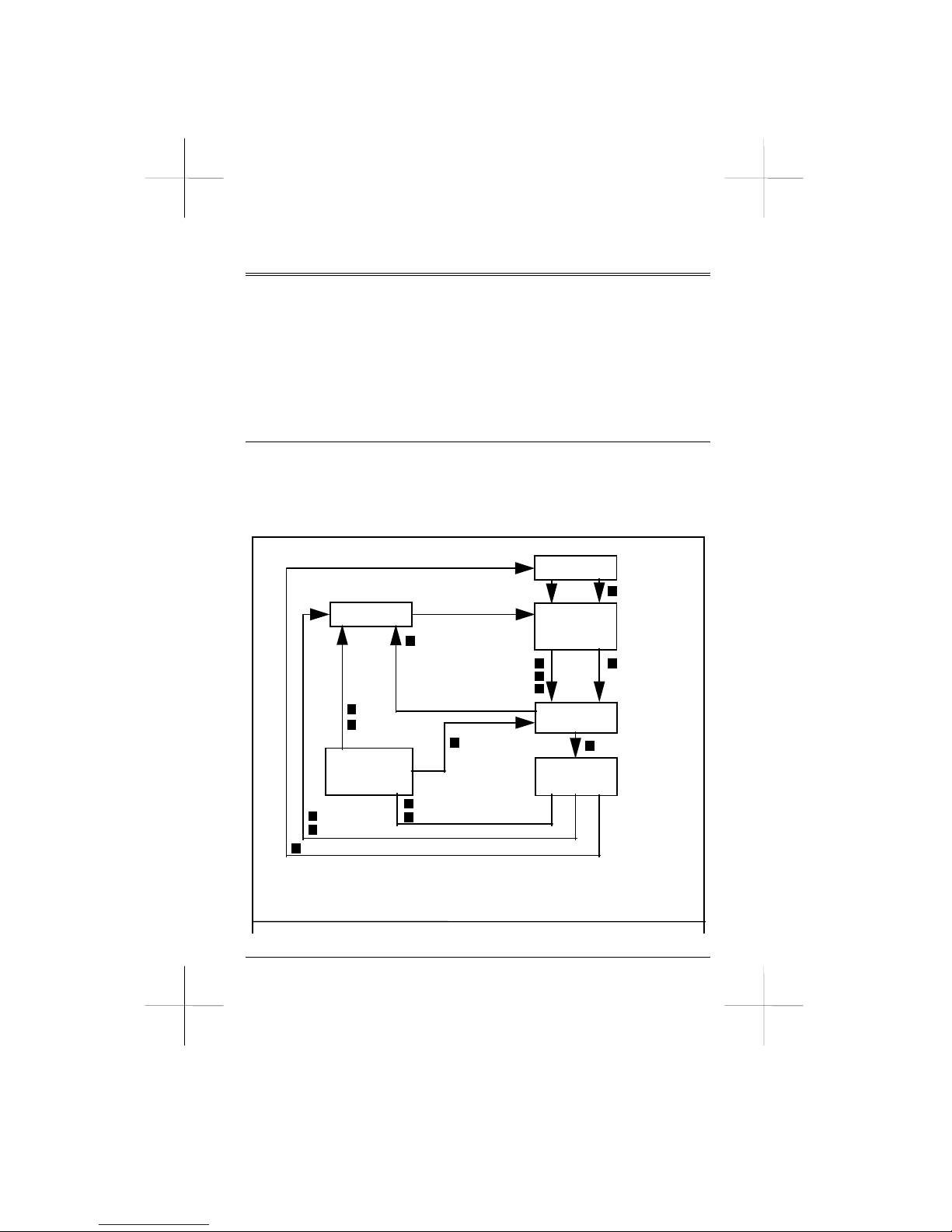
During operation, your modem is either in command state or data state.
The figure below shows the relationships between the two states and
how to enter and abort from each.
In command state, the modem interprets all characters it receives as
Page: 22
Power Up
Off-Line
Command
State
Connecting
On-Line
State
ATZ
DTR off-to-on
(&M2,&M3)
ATD
ATA
Auto-Answer
Power Up
On-Line
Command State
(Async mode only
)
Connection Established
Escape
DTR Loss (&D1)
Carrier Loss
DTR Loss (&D2)
ATO
Fail to Connect
ATH
DTR Loss
(&D2,&D3)
DTR Loss (&D3)
Fig 3-1 Command State and Data State
Page 23

commands. Command state may either be on-line or off-line. When the
modem is holding a connection with a remote modem or when it is in
an analog loopback test, it is on-line. Otherwise, it is off-line.
In data state, the modem is a transparent receiving and sending device.
It interprets everything it receives (except the escape sequence) as data
and conveys the data to the local computer or remote system.
3.2 Escape Sequence
The escape sequence instructs the modem to leave (escape) data state
and enter command state, without breaking the connection. This is the
only data string interpreted as a command when the modem is in data
state.
After switching to command state, users can issue further commands,
such as changing parameter settings, etc. To resume data state, simply
issue ATO.
The escape command in default is three consecutive "+" characters. In
order for the modem to distinguish an escape command from data, a
certain duration of guard time should exist both prior to and after the
three consecutive escape characters. Therefore, the escape sequence
includes first, a guard time, second, three consecutive escape
characters, and last of all, a guard time.
The guard time in default of S12 is 1 second and is changed by
assigning a different value to register S12. Likewise, you may change
the escape character by assigning an ASCII value (in decimal) for the
new escape character to register S2.
3.3 Modem Speeds
During an on-line communication path, your modem is located
between the local computer and remote modem. It has to communicate
with both the remote modem and local computer through the telephone
line and serial port cable, respectively.
The speed over the telephone line at which your modem communicates
Page: 23
Page 24

with remote modems is called the on-line speed. Since modems are
Data Communication Equipment, this is called the DCE speed.
On the other hand, the speed over the serial port at which your modem
communicates with the local computer is called the serial port speed.
Since computers are Data Terminal Equipment, this is called the DTE
speed.
3.4 Smart and Dumb Mode
Smart/Dumb Mode configures the modem to either smart or dumb
mode. In smart mode, the modem recognizes commands and echoes
the response codes. This is the modem's default setting and applies to
general modem applications in dialup operations.
In dumb mode, the modem ignores commands and refrains from
sending response codes. Dumb mode allows the modem to act as a
dedicated auto-answer modem or configures the modem for
synchronous mode 2 or 3 operation. Smart/Dumb mode is configured
through the LCD control panel in the SETUP Main Menu: Command
Directory, under MODE SELECT or by issuing the proper @I
command.
To exit Dumb Mode, and return to start mode by entering the SETUP
Main Menu: Command Directory, under AT. Enable AT (you should
hear a "beep" and see an "*" before AT). Now press the Voice/Data
button on the modem front panel. On your computer monitor you
should see NO CARRIER. If not, continue to press the V/D button
until it appears.
After you've changed smart mode to dumb mode or dumb mode to
smart mode, if you want next time you turn on the modem and still
keep the change, you shound use keyboard to enter the command
AT&W or use LCD control panel into PROFILE main directory: under
SAVE PROFILE to save the change to NVRAM.
Page: 24
Page 25

3.5 Factory Default Profile FDP
The FDP is the default configuration profile stored in your modem's
read-only memory (ROM), which is not to be modified by the user.
For convenience in different applications, the modem supports 13
FDPs (FDP0 through FDP12).
3.6 Stored Configuration Profile SC
The SCP is the configuration profile stored in the modem NVRAM
which can be retrieved for further use. There are 4 SCPs your modem
can retain: SCP0, SCP1, SCP2, and SCP3.
SCP1 is the configuration profile factory setting for ECDC operation
for PC users. SCP2 is for non-ECDC use for PC users. SCP3 is for
Macintosh or terminal users for ECDC operation. SCP4 is for
Macintosh or terminal users for non-ECDC operation. The table below
lists the SCPs and their corresponding profiles and operation modes.
Operation Mode &F Command
SCP1 ECDC (&C1,&D2)
SCP2 non-ECDC (&C1, &D2)
SCP3 ECDC (&C0, &D0)
SCP4 non-ECDC (&C0, &D0)
3.7 Major Stored Configuration Profile Major SCP
The major SCP is loaded to ACA each time the modem is turned on or
reset by ATZ. To designate an SCP as the major SCP, issue command
&Y followed by the SCP number.
You may load a selected SCP to ACA by issuing ATZ followed by the
SCP number. In this case, however, the selected SCP is used only in
that particular session. Once the modem is turned on or reset by ATZ,
the major SCP is still loaded.
Page: 25
Page 26

3.8 Active Configuration Area ACA
The ACA is a portion of the random-access-memory (RAM) in your
modem that holds the configuration settings which determine the
modem's current operating characteristics.
When the modem is turned on or reset by command Z, the ACA is
loaded with the FDP (from the modem firmware ROM) and then
overwritten by the major SCP (from the NVRAM). The commands
you issue to modify the modem configuration actually changes the
content of the ACA. However, once the modem is turned off, all the
settings in the ACA will vanish.
To save the current ACA configuration to a SCP for further use, issue
command &W followed by the SCP number.
Issuing command &V0 will display the current major configuration
profile, the stored configuration profiles, as well as the current speed,
data format, parity, and protocol.
3.9 Stored Telephone Numbers STN
STNs are the digits retained in the modem NVRAM to be used for
dialing. You may save frequently used telephone numbers, passwords,
or credit card numbers in it. Note that only digits can be stored in STN
and other characters or symbols will be discarded.
To store a telephone number as an STN, use commands &Z0 through
&Z9, followed by "=" and the telephone number. To view STN, issue
command &V1. To dial an STN, issue S=n or /n, n denoting the nth
STN.
For example:
AT&Z2=886-2-782-2456 Stores 88627822456 as STN2.
ATDT/3/7 Dials STN3 followed by STN7.
Page: 26
Page 27

Chapter 4
SPECIAL FUNCTIONS
This chapter describes special modem operation functions and is
designed to help users understand the modem in a greater detail.
4.1 Speed Dialing
Speed dialing lets you issue abbreviated dialing codes instead of whole
telephone numbers and requires telephone numbers to be saved in STN.
To use speed dialing, specify command S=n or command /n (n=0-9).
For example:
AT &Z2=782-2456 Stores 782-2456 as STN2.
AT DT S=2 Dials STN2 (782-2456).
AT DT /2 Dials STN2 (782-2456).
AT DT 886-2 /2 Dials 886-2 STN2 (782-2456).
AT DT 886-2 S=2 Dials 886-2 STN2 (782-2456).
4.2 Swap Dialing
Swap dialing automatically dials another telephone number when the
first number is busy, by specifying two numbers spaced by swap
dialing command N. When the modem goes to dial, it dials the first
number. If the first specified number is busy, the modem dials the
second number.
For example:
ATX4DT7822456N7822591 The modem dials 782-2456 first,
if busy, then disconnects and
dials 782-2591 if the first
number is busy.
ATX4DT S=2 N S=5 Speed dialing can be combined
Page: 27
Page 28

ATX4DT /2 N /5 with swap dialing. Both command
lines instruct the modem to dial STN2
first. If STN2 is busy, STN5 is swap
dialed. Note that to use swap dialing,
busy detection must be enabled by
command X3 or X4.
4.3 Redialing
Your modem can automatically redial a call if the line is busy. To do
so, issue the appropriate N= and N5= commands.
For example:
AT X4 N=5 N5=15 DT 782-2456
Redials the number 782-2456 every 30
seconds and up to 5 times if the line is
busy. Note that command X3 or X4
should be issued to enable busy
detection.
4.4 Leased Line Operation
In addition to dialup line operation, the modem can be used on a leased
line for dedicated communications between two destinations. To set up
a pair of modems for leased line communications, follow the
procedures below:
1. Connect two modems on the 2 wire or 4 wire leased line and
make sure the 2 wire or 4 wire leased line is connected to the
modem phone jack. Use the RJ-45 to Y-connector cable supplied
with your modem (see Appendix B). Leased line wires should be
connected to the two or four outside wires.
2. Make sure both modems are in smart mode so they can accept
commands.
3. Issue command &L1 (2 wire) or &L2 (4 wire) to both modems to
select leased-line operation.
4. Issue command ATD to one modem to initial it for dialing mode.
Page: 28
Page 29

5. Issue command ATA to the other modem to initial it for
answering mode.
6. The two modems should then establish a connection and go online through the leased line.
Note that two modems on a leased line link must be set to exactly the
same protocol, one in dialing mode and the other in answering mode.
To set the modem to auto answer mode, assign a non-zero value to
register S0. The AA (Auto Answer) indicator on the modem front
panel will be lit.
4.5 Power On Leased Line Operation
In leased line applications, the modem can be set to automatically
connect with a remote site each time it is turned on and continuously
attempt to establish a leased line connection with a remote modem
until successful. For power on leased line operation:
1. Set your modem for leased line operation as explained in the
previous section.
2. Issue AT&F&L1S0=1@I1&W to one modem, setting it as the 2
wire leased line answering modem.
3. Issue AT&F&L1S0=0@I1&W to the other modem, setting it as
the dialing modem(Simply change &L1 to &L2 in step 2 and step
3 for 4 wire leased line system.).
4. Both modem are now ready for power on leased line operation.
5. You can also set up your modem by using LCD control panel
from step 2 to step 3.
6. Once you've saved dumb mode setting to your modem's NVRAM
and next time when you turn on your modem it will not accept
AT command, you should only use LCD control panel to change
it return to smart mode.
Page: 29
Page 30

4.6 Leased Line Dialup Backup
The modem supports a dialup backup capability, which automatically
dials STN0 through the connected dialup line when the leased line
carrier is lost. Thus, a backup connection is automatically initiated if
the leased line is disconnected.
AT@Y2 Issue this command after connecting both the
leased line and dial up line to the modem.
AT@Y0 Issue this command to disable the dial up
back up function, whether the dial up line is
connected or not.
ATS15=10 Switches back to the leased line 10 minutes
after establishing a connection through the
dialup line and detects if a leased line
connection can be established. Functional
only in dial mode.
ATS13=200 Limits the number of times the modem
switches between the leased line and dial up
line to 200 times.
ATN=3 When the dial up line is busy, the redial
times does not exceed 3 times.
AT-B2 After the leased line is disconnected, the
number of retries does not exceed 2 times.
ATD or ATA Executes the Dial or Answer commands.
4.7 ITU-T V.23 Operation
In ITU-T V.23 mode, the modem operates at 1200 bps in one direction
and 75 bps in another. In many countries this protocol is mainly used
for Videotex services, including BTX and Minitel.
B2 The modem uses the V.23 backward channel, transmits at
Page: 30
Page 31

75 bps and receives at 1200 bps. For Videotex service.
B3 The modem uses the V.23 main channel, transmits at
1200 bps and receives at 75 bps. For host side use.
With either user or host channels, once the modem connects in V.23
mode, it responds with CONNECT 1200 and data speed between the
modem and computer is fixed at 1200bps in both directions. The 75bps
path is buffered by the modem and controlled by the RS-232C CTS
(Clear To Send) signal to prevent overflow.
4.8 Power On Auto Dialup
After the power is turned on, the modem can immediately dial the Nth
telephone number set. Note that telephone numbers must first be set up
with command &Zn= before using this function.
AT&A&W When the power is turned on, the modem
dials the STN 0 telephone number set and
saves it as the major profile.
AT&A3&W When the power is turned on, the modem
dials the STN3 telephone number set and
saves it as the major profile.
4.9 Dialup Simulate Leased Line
If the dial up line is disconnected due to the line circuit, the modem
can immediately establish a connection. If the disconnection is due to
human factors, such as DTR disconnection or ATH, then the modem
will not attempt to establish a connection.
AT@Y1 Enables the dialup simulate leased line
function.
ATDxxx Executes the Dial command.
Page: 31
Page 32

4.10 Connection Password Security
Your modem supports connection password security, which prevents
unauthorized connection to your modem.
@E1 Enables connection password security
and your modem waits for a password
from the calling modem. If the correct
password is received, the modem
establishes a connection, otherwise it
responds with NO CONNECTION.
ATDT 782-2456,,,123 Remote modem callers should type
123 for connection, if your connection
password is 123.
The modem waits 15 seconds for passwords, and assigning a different
value to register 48 changes the waiting period. Note that the number
of commas (waiting period) you type after the telephone number can
not not exceed the S48 value.
@P= Sets the connection password (up to 9 digits,
0-9, *, and # on a touch tone telephone
keypad.
AT@P=7452 Sets the local modem connection password.
AT@E1 Enables the local modem to connect the
password.
ATS48=15 Instructs the local modem to disconnect if no
password is entered within 15 seconds.
ATA or S0=1 Determines when the ring comes in.
@F Views the password.
Page: 32
Page 33

4.11 Remote Access (RA)
The modem supports remote access operation and remote access
security. For remote access, first turn on the remote access second
channel in the LCD SETUP Main Menu: Remote Access Directory.
After the RA SEC CHANNEL is ON, you can configure or issue
commands from remote sites. If the RA SEC CHANNEL is OFF, you
cannot use the remote access function.
@F Views the RA password.
*E Enables (*E1) or disables (*E0) RA
capability and is used for security purposes.
Issue command *E1 for RA links, but note
that RA links are only possible if the RA
SEC CHANNEL in the REMOTE ACCESS
directory is activated, in addition to
command *E1.
*P Set RA Password.
4.12 VAR Password Protection
With VAR Password Protection, software developers (Value-Added
Reseller, VAR) can implement check points so software executes predesigned subroutines or quits execution if incorrect VAR passwords
are detected. If passwords are correct the modem responds with OK,
otherwise it responds with ERROR. Besides many other applications,
this feature protects VARs from software pirates who illegally
duplicate software.
AT@S0<old password>; <new password> (Set new VAR
Password)
AT@C0=<password> (Checks the VAR password)
Page: 33
Page 34

4.13 Call Back Security
Call back security protects against callers without the right to access
your system, allowing you to limit incoming calls to selected persons.
Call back security allows 10 telephone numbers to be stored in the
NVRAM.
After connection with the local modem, an opening message is sent to
the caller. Then, at the password prompt, callers have ten seconds to
enter the call-back password.
If the correct password is received, a goodbye message is sent, ending
the call back security checking procedure and followed by a hang up.
The telephone number corresponding to the received password is
called in the delay time specified by command @D. If an incorrect
password is received or if there is inactivity for more than ten seconds,
the modem hangs up.
AT@A1 Enables call back security.
AT@Z3=7820041 Sets the 3rd telephone number set as 782-
0041.
AT@W3=MISC Sets the 3rd telephone number set password
as MISC.
AT@D10 Enables a 10 second delay between
successful password entry and the matching
dial back telephone number set.
ATA or S0=1 Determines when the ring comes in.
4.14 Automatic Detection of Data/Fax/Voice Call
With standard AT, fax and Voice/Audio command set, the Discovery
2814LC modem can automatically detect data, facsimile, and voice call,
and give a proper response immediately. For more details about the
usage, please refer to the Data/Fax/Voice multi-communication
software user's manual bundled with the modem.
Page: 34
Page 35

4.15 V.25bis Operation
Your modem is equipped with ITU-T V.25bis protocol, which allows
you to enter PSDN through PSTN, while in synchronous mode.
The Discovery LCD modem supports Asynchronous Mode, Synchronous HDLC Mode (Bit Sync Mode), and Synchronous BSC Mode
(Byte Sync Mode). The following are the commands to enter the three
modes:
*C0 Disable V.25bis.
*C1 V25bis Async.
*C2 V25bis Bisync.
*C3 V25bis HDLC
Please note the following before setting you modem to the above
mentioned modes.
1. Remember to issue command &W after the setting if you want to
save it.
2. Only in V.25bis Asynchronous Mode you can issue V.25bis
commands (hardware control). In HDLC Mode and BSC Mode you
need a synchronous card to issue V.25bis commands.
Command Instructions:
The following are V.25bis commands, their definitions, and
instructions for use.
1.) CIC (Connect Incoming Call)
Definition: To clear DIC (Disregard Incoming Call), to respond
to incoming call.
Limits: DTR should be on and INC counter >0(S1>0).
Page: 35
Page 36

Message: If commands are issued properly, you can execute
ATA actions (manual answering), and you will
receive a CNX response. If the proper commands
were not issued, you will receive an INV (failure)
response.
2.) CRN (Call Request with Number)
Definition: Dial command like ATD.
Limits: None.
Message: If a failure occurs while executing CRN commands,
the following responses will be issued:
CONDITION
RESPONSE
1. DTR Off INV
2. Parameter Error INVPV
3. No Dial Tone CFIAB
4. No Carrier CFIRT
5. No Answer CFINT
6. Busy CFIET
For example:
Command and Response
Status Instruction
1. CRN2577125 DTR Off Dial
INV DTR is off
2. CRN257AB25 Telephone number:
INVPV only 0-9, w, , , >, P,
T, !, and spaces.
3. CRN2577125 Busy Dial
CFIET Busy
3.) CRS (Call Request with Memory Address)
Definition: Like command ATDS.
Limits: None.
Message: Same as CRN.
Page: 36
Page 37

Example: CRS 1 (Dials STN1)
2577125
CFIRT (No Carrier)
4.) CNL (Extended V.25bis Command Set)
Definition: Executes any AT command except *, %, +, -, &T,
&V(Note:&V only effect in Async V.25bis mode.)
Limits: None.
Message: Successful response is VAL.
Failed response is INVCU.
Example: 1.CNLX4B1
VAL
2.CNL&T
INVCU (&T is not the correct command)
5.) DIC (Disregard Incoming Call)
Definition:
Limits: S0 and S1 can not equal 0.
Message: Successful response is VAL.
Failed response is INV.
Example: 1. INC (S0 not equal to 0, S1 not equalto 0)
DIC (DTE command)
VAL
2. (S0=0)
DIC
INV
3. (S0 not equal to 0, S1 not equal to 0)
DIC
INV
Page: 37
Page 38

6.) RLN (Request List of Stored Telephone Number)
Definition: Similar to command &V1.
Limits: None.
Message: Successful response is VAL.
Failed response is INVPV.
Example: 1. RLN (Lists all)
LSN 0;
LSN 1; 318
:
:
LSN 9 ; 7822456
VAL
2. RLN 1 (Lists STN1)
LSN 1; 318
VAL
3. RLN 10 (Lists STN0)
INVPV (Range: 0-9)
7.) PRN (Program Telephone Number)
Definition: Stored telephone number to STNn.
Limits: None.
Message: Successful response is VAL.
Failed response is INVPS.
Example: 1. PRN 2 ; 433 (Sets STN2=433)
VAL
RLN 2 (List STN2)
LSN 2 ; 433
VAL
2. PRN 2 (Clears STN2)
VAL
RLN 2
LSN 2
Page: 38
Page 39

VAL
3. PRN 10
INVPV (Range: 0-9,)
Reponse Message Definitions
The following are response messages followed by their definition.
1. INC: Like AT command "ring message."
2. CNX: Like AT command "connect message."
3. VAL: Like AT command "OK message."
4. INVxx: Like AT command "error message."
5. CFIxx: Like AT command ATD's "error message"
INVCE: Command Unknown/Unexpected Error
INVMS: Message Syntax Error
INVPS: Parameter Syntax Error
INVPV: Parameter Value Error
CFUET: Remote Busy
CFINS: Telephone Number not stored
CFICB: Local Busy
CFIRT: No Carrier
CFIAB: Abore Call/No Dialtone
CFINT: No Answer
CFIFC: Forbidden Call
Page: 39
Page 40

4.16 Voice/Audio Function
In addition to data communication and fax transmission, Discovery
2814LC also can run with Voice/Audio management software.
Running with the software, Discovery 2814LC can support about 1000
voice mail boxes., receive voice messages, and listen to the voice
message or delete message at any time even from remote site. The
functions are better not only than answering machine but also
telephone-secretary system. For more details, please refer to the
Data/Fax/Voice multi-communication software user's manual. The
author of the software also release complete Voice/Audio command
(appendix E) as a reference for Voice/Audio programmer.
Page: 40
Page 41

Chapter 5
COMMAND REFERENCE
This chapter describes all the available modem commands. The default
settings, if applicable, are indicated by bold characters. Note that in
order to meet local telephone company regulations, some modem
commands might have been removed or set to a different default.
5.1 Answer Call Immediately A
Command A instructs the modem to take the telephone line off hook
and generate a carrier tone. Incoming calls are manually answered.
5.2 Manual Answer and Auto Answer An
Range: n=0-255 Unit: Rings
Command An instructs the modem to immediately answer incoming
calls. The number of rings by which the modem goes off hook to
answer is determined by register S0.
If a number follows command An, the modem goes off hook to answer
on the specified number of rings.
For example:
A3 Instructs the modem to auto answer on the third ring and
then enter data state after a connection is successfully
established.
5.3 Attention Code AT
Command AT clears the command buffer and informs the modem of
your computer‘s transmission speed and data format. Any command
line, except A/ and +++, must start with an AT prefix and end with a
carriage return.
Page: 41
Page 42

5.4 Repeat Last Command A/
Command A/ instructs the modem to re-execute the last command line
stored in the command buffer. This is the only command that does not
require an AT prefix and carriage return.
5.5 Bell or ITU-T Standard B
Command B selects the following communications protocols:
B0 Selects ITU-T/Bell auto protocol, used in most
countries around the world.
B1 Selects Bell protocol, used mainly in U.S.A. and Canada.
B2 Selects ITU-T V.23, Back Channel.
B3 Selects ITU-T V.23, Main Channel.
5.6 Dial In Originate Mode D
Command D instructs the modem to dial the number following it and
enter data state after a connection is established.
The number following command D may include the digits 0 through 9,
dial modifiers A, B, C, D, N, P, T, R, S, S=n, W, the symbols *, #, @, ,
(comma), ! (exclamation), ; (semicolon), and /n.
Swap Dialing N
Inserting command N between two telephone numbers in a dial
command line instructs the modem to swap dial the second specified
number if the first number is busy.
For example:
AT X4 DT 782-2456 N 782-0305 The modem dials
782-2456 first; if
782-2456 is busy, it swap
dials 782-0305.
Page: 42
Page 43

To use swap dialing, either X3 or X4 must be in effect so the modem
can detect a busy signal.
Dial In Answer (Reverse) Mode R
Attaching command R at the end of a dial command line instructs the
modem to place a call and establish a connection in answer mode.
Reverse mode dialing is useful when calling an originate-only modem.
Dial Stored Telephone Number S=n(or/n)
Issuing dial modifier S=n after dial command D instructs the modem to
dial the stored telephone number (STN) previously saved with
command &Zn.
For example:
AT &Z2=782-2456 Saves 782-2456 to STN2.
AT DT S=2(or/2) Dials 782-2456 (STN2).
AT DT 886-2 S=2(or/2) Dials 886-2-782-2456.
AT DT S=2 N/4 Dials STN2; if STN2 is busy,
STN4 is swap dialed.
When dial modifier S=n is used, the command buffer will count S=n as
three characters. Also, dial modifier S=n must be preceded by dial
command D, DT, or DP.
Pause , (Comma)
Command , (comma) instructs the modem to wait for the time interval
specified by register S8 before proceeding with the commands
following it in the command line.
The duration of the pause is default at 2 seconds and is changed by
assigning a new value to register S8. You may use multiple commas in
sequence for a longer pause time.
Wait For Silent Answer @
Page: 43
Page 44

Command @ instructs the modem to wait for the time specified by
register S7 and followed by 5 seconds of continuous silence, before
proceeding to dial the following digits.
The modem will disconnect and respond with NO ANSWER if it fails
to detect continuous silence, or respond with BUSY if it detects a busy
tone (either X3 or X4 must be in effect).
Flash ! (exclamation)
Command ! (exclamation) instructs the modem to go on hook for half a
second and then off hook. This command is used for call transferring.
Return to Command State ; (semicolon)
Ending a dial command line with command ; (semicolon) instructs the
modem to enter command state after dialing, rather than going on-line
and into data state. Other commands may follow command ; in the
same command line.
5.7 Command Character Echo E
Command E enables or disables the sending of command characters
back to the computer. It is only effective in command mode.
E0 Displays the echo of command characters. It is used when
command characters appear in double on your screen or
when you use the modem with a host computer and do not
want the command characters echoed.
E1 Enables the modem to echo command characters to
your computer to view and verify the command line on
the screen.
Page: 44
Page 45

5.8 On or Off Hook H
Command H instructs the modem to go off hook (use the telephone
line) or go on hook (hang up).
H0 Modem goes on hook.
H1 Modem goes off hook.
5.9 Identification I
Command I allows the modem‘s product code and firmware version to
be checked, and executes firmware tests.
I0 Displays the modem‘s product code (Part I).
I1 Displays the checksum code of the modem‘s firmware
ROM in ASCII digits followed by a carriage return and
line feed.
I2 Executes the modem‘s checksum test and sends an OK or
ERROR response code.
5.10 TX Level K0=n
Range: n=0~15 default: 10
Command K0=n determines the carrier level control (-n dbm).
TX level setting:
Leased line TX level: 0 ~ -31dBm
Dial line TX level: 0 ~ -15dBm
5.11 Speaker Volume L
Command L adjusts the modem speaker volume for call progress
monitoring. When the speaker is turned on:
L0 Selects off speaker volume.
Page: 45
Page 46

L1 Selects low speaker volume.
L2 Selects medium speaker volume.
L3 Selects maximum speaker volume.
5.12 Speaker On or Off M
Command M turns the modem‘s speaker on or off for call progress
monitoring.
M0 Turns the speaker off at all times.
M1 Turns the speaker on until a connection is established.
M2 Turns the speaker on at all times, even after a connection
is established.
M3 Turns the speaker on until a carrier is detected, but turns
the speaker off when the modem is dialing.
5.13 Redial Times N=n
Range: n=0-15 Unit: Times Default: 0
Command N=n determines how many times the modem redials a call if
a busy signal is detected. The default setting is N=0 so the modem will
not redial.
Note that the redial function is cancelled if you abort dialing.
5.14 Redial Interval N5=n
Range: n=0-255 Unit: 2 sec Default: 1
Command N5=n adjusts the time interval between redialing, where n
denotes the interval in seconds.
For example:
N5=45 Instructs the modem to redial a call every 90
seconds.
Page: 46
Page 47

5.15 Read Redial Count N?
Issuing N? displays the redial times setting.
5.16 Read Redial Interval N5?
Issuing command N5? displays the time interval between the number
of redial times.
5.17 On-Line O
Command O instructs the modem to enter on-line data state.
O0 Instructs the modem to enter on-line data state and resume
data transmission with the remote modem.
O1 Instructss the modem to enter on-line data state and
initiates an equalizer retrain sequence at the same speed.
This is used when excessive bit error rates occur and a
retrain might reduce the errors attributed to a loss of
equalization. Note that this command is effective only at
2400 bps or above.
5.18 Pulse Dialing P
Inserting command P before a telephone number instructs the modem
to pulse dial the number. You may insert command P anywhere in a
dial command line, even between digits.
For example:
AT DT 9 , P 782-2456 Instructs the modem to tone dial 9,
wait for two seconds (comma
character), and then pulse dial 782-
2456.
Page: 47
Page 48

5.19 Response Codes Q
Command Q enables or disables the sending of response codes after a
command line is executed.
Q0 Enables the sending of response codes.
Q1 Disables the sending of response codes. This feature is
useful if the modem is connected to a printer that prints
out undesired response code characters.
5.20 Read Register Sr?
Command Sr? displays the content of register r.
For example:
ATS7? Displays the value stored in register S7.
ATS5?S7? Displays the values in both register S5 and S7.
5.21 Set Register Sr=n
Command Sr=n sets register r to value n.
For example:
ATS0=3 Sets register S0 to3.
5.22 Touch Tone Dialing T
Inserting command T before a telephone number instructs the modem
to tone dial the number. The tone dialing speed is determined by
register S11.
You may insert command T anywhere in a dial command line, even
between digits, to have the modem tone dial the following digits.
Page: 48
Page 49

For example:
AT DP 9 , T 782-0002 Instructs modem to pulse dial 9,
wait for two seconds (comma
character), and then tone dial 782-
0002.
5.23 Word or Digital Response Codes V
Command V instructs the modem to send response codes in either
word or digit form.
V0 Sends response codes in digital form. This form is
convenient when using the modem with software that
does not handle character strings efficiently.
V1 Sends response codes in word form, such as OK or
CONNECT. This form is easier for users to read.
5.24 Wait For Second Dial Tone W
Inserting command W in a dial command line causes the modem to
wait for a three second continuous dial tone before proceeding to dial
the digits following it. The modem will respond with NO DIAL TONE
if it fails to detect the tone or with BUSY if the line is busy.
5.25 Response Set Xn
Range: 0~4 Default: 4
Command Xn determines which response code is enabled or disabled.
X0 Enables basic set of response codes 0-4.
X1 Enables response codes 0-5, and 10-end.
X2 Enables response codes 0-6, and 8-end.
X3 Enables response codes 0-5, and 7-end.
X4 Enables all standard response codes.
Page: 49
Page 50

5.26 Clear Down Disconnect Y
This command enables or disables the modem clear down disconnect
feature.
Y0 Disables clear down and long space disconnect.
Y1 Enables long space disconnect. The modem hangs up
when it receives 1.6 seconds of continuous break signal.
Also, it sends a 4 second break signal before
disconnecting when it receives command ATH or when it
detects a DTR on-to-off transition if &D2 option is
selected.
Y2 Enables clear down disconnect.
5.27 Reset Zn
Command Zn resets the modem a with factory default profile (FDP)
and a stored configuration profile (SCP).
Z0 Resets the modem with FDP and then with the major SCP
(if command &Y is in effect).
Z1 Resets the modem with SCP1.
Z2 Resets the modem with SCP2.
Z3 Resets the modem with SCP3.
Z4 Resets the modem with SCP4.
5.28 Power On Auto Dial with STN &An
Range: n=0-9, 99. Default: 99 (disable)
Command &An instructs the modem to automatically dial a STN
(denoted by n and saved with the appropriate &Z= command)
everytime the modem is turned on.
Page: 50
Page 51

5.29 CD Option &C
Command &C determines how the modem reacts to the conditions of a
CD (Carrier Detect) interchange circuit.
&C0 CD is always forced ON.
&C1 Modem tracks the data carrier from the remote
modem and initials CD accordingly.
5.30 DTR Option &D
This command determines how the modem reacts to a DTR (Data
Terminal Ready) on-to-off transition.
&D0 Instructs the modem to ignore a DTR.
&D1 Instructs the modem to assume command state upon
detecting a DTR on-to-off transition, but maintains an
active line connection.
&D2 Instructs the modem to go on hook, assume command
state, and disable auto answer upon detecting a DTR
on-to-off transition. The auto answer function can be
re-enabled by turning DTR on again.
&D3 Instructs the modem to re-initialize itself when it detects a
DTR on-to-off transition. The ACA is overwritten by the
active SCP.
5.31 Load Factory Default Profile &F
Commands &F0 through &F12 load the factory default profile (FDP)
into the modem's Active Configuration Area (ACA). The FDP is
viewed by issuing command &V.
&F0 For asynchronous, dialing, V.42bis ECDC links.
&F1 For asynchronous, answering, V.42bis ECDC links.
&F2 For asynchronous, answering, direct links.
Page: 51
Page 52

&F3 For asynchronous, answering, direct links.
&F4 For asynchronous, dialing, normal links.
&F5 For asynchronous, answering, normal links.
&F6 For synchronous, dial in links.
&F7 For synchronous, answering, direct links.
&F8 For synchronous, V.25bis links.
&F9 For synchronous, V.25bis Bisync links.
&F10 For synchronous, V.25bis, Data package links.
&F11 For power on, 2 wire, leased line.
&F12 For power on, 4 wire leased line.
5.32 Guard Tone &G
Command &G selects the guard tone in ITU-T V.22 and V.22bis
modes and is effective only in these modes.
&G0 Disables guard tone.
&G1 Selects 550 Hz guard tone.
&G2 Selects 1800 Hz guard tone.
5.33 Leased Line or Dialup Line &L
Command &L is issued according to the type of telephone line used
with the modem.
&L0 Sets the modem for dialup line operation.
&L1 Sets the modem for 2 wire leased line operation.
&L2 Sets the modem for 4 wire leased line operation.
Page: 52
Page 53

5.34 Asynchronous or Synchronous Mode &M
Command &M is issued to determine synchronous or asynchronous
communications mode operation. Note that this command has the same
function as command &Q.
&M0 Sets the modem to asynchronous mode to accept
asynchronous commands.
&M1 Sets the modem to synchronous mode 1
(asynchronous dialing).
&M2 Sets the modem to synchronous mode 2
(DTR on-to-off transition, can dial STN0 immediately).
&M3 Sets the modem to synchronous mode 3
(DTR on-to-off transition, starts handshaking directly).
5.35 Pulse Dialing &P
Command &P determines the pulse dialing method. Note that
command &P is effective only when pulse dialing.
&P0 Selects the make/break ratio of 39/61 for modem use in
U.S.A. or Canada.
&P1 Selects the make/brake ratio of 33/67 for modem use in
United Kingdom or Hong Kong.
5.36 Asynchronous or Synchronous Mode &Q
Command &Q has the same functions as command &M. See the
command &M section.
5.37 CTS to RTS Option &R
Command &R determines how the modem reacts to a CTS (Request
To Send/ Clear To Send) signal. Note that command &R is effective
only in synchronous mode.
&R0 CTS will follow the condition of RTS.
Page: 53
Page 54

&R1 RTS is ignored and CTS is forced on.
5.38 Data Set Ready (DSR) Option &S
Command &S determines how the modem operates the DSR Data Set
Ready) signal. Note that command &S is effective only in synchronous
mode.
&S0 DSR is forced on.
&S1 DSR operates according to EIA RS-232C specifications.
5.39 Diagnostic Tests &T
Command &T instructs the modem to perform various diagnostic tests.
See the Chapter 6 of this manual for further details.
5.40 Read Configuration Profile &V
Command &V displays the stored configuration profile (SCP), the
stored telephone number (STN), and current modem operation states.
&V0 Displays ACA, SCP, and current modem operational
status.
&V1 Displays STN.
5.41 Write Configuration Profile &W
Command &W writes the content in the active configuration area
(ACA) to one of the stored configuration profiles (SCP).
&W0 Writes ACA to the major SCP.
&W1 Writes ACA to SCP1.
&W2 Writes ACA to SCP2.
&W3 Writes ACA to SCP3.
&W4 Writes ACA to SCP4.
After saving a profile, enable it by issuing the proper &Y command.
Page: 54
Page 55

5.42 TX Clock &X
Command &X selects the TX clock setting in synchronous mode.
&X0 Sets Internal TX clock to Pin 15 (RS-232).
&X1 Sets External TX clock from Pin 24 (RS-232).
&X2 Sets Slave TX clock to Pin 15 (RS-232).
5.43 Major Stored Configuration Profile &Y
Command &Y assignees a stored configuration profile (SCP) as the
major SCP, which is used when command Zn or &W are executed or
when the modem is turned on.
&Y1 Assigns SCP1 as the major SCP.
&Y2 Assigns SCP2 as the major SCP.
&Y3 Assigns SCP3 as the major SCP.
&Y4 Assigns SCP4 as the major SCP.
5.44 Stored Telephone Number &Zn=
Range: n=0-9
Command &Zn=x stores the telephone number following it as an STN,
to be used later by issuing dialing modifiers S=n or /n.
For example:
AT &Z0=782-2456 Stores 782-2456 as STN0.
AT &Z9=02-782-0305 Stores 02-782-0305 as STN9.
AT &Z9= Clears STN9.
Each STN can contain up to 49 digits with a total length of not more
than 10 sets per 100 digits. Spaces are ignored and will not be stored.
5.45 Escape Character +++
Page: 55
Page 56

Escape character (+++) instructs the modem to leave data state and
enter command state without breaking the connection. Note that this
command is only effective in asynchronous mode.
For the modem to distinguish escape characters from data, escape
characters must be preceded and proceeded by a guard time period.
This is called the escape sequence. To enter the escape sequence while
the modem is on line in data state:
1. Wait for one second of guard time without typing or transferring
anything.
2. Enter the three consecutive escap e characters (+++). Do not press
the return key.
3. Wait for another second of guard time without typing or
transferring anything.
Upon recognition of the escape sequence, the modem sends an OK
response code and escapes to command state.
The default escape character is + (ASCII 43) and the default guard
time is one second. Both are changed by adjusting the values in
registers S2 and S12, respectively.
5.46 Call-Back Security @A
Command @A enables or disables the call back security function.
@A0 Disables callback security.
@A1 Enables call back security.
5.47 Ring Sound Control @B
Command @B enables or disables the ringing sound generated through
the modem speaker when an incoming ring is detected.
@B0 Disables incoming ring sound.
@B1 Enables incoming ring sound.
Page: 56
Page 57

5.48 Check VAR Password @Cn
This command checks the passwords VP0 and VP1.
@C0 Check VAR Password VP0.
@C1 Check VAR Password VP1.
To check the VAR password VP0 or VP1, you can flow the syntax
below with the corresponding response depending on the validity of
the password issued.
Syntax:
AT@Cn=<pattern> <CR>,where<pattern>is the VPn.
Response:
OK If<pattern>=<VP0>or<VP1>
ERROR If<pattern>is not equal to <VP0/VP1>
5.49 Call Back Security Time Delay @Dn
Range: 1-255 Unit: sec Default: 30
Command @Dn instructs the modem to wait for the specified delay
time before proceeding to dial the caller's telephone number.
5.50 Connection Password Security @E
Command @E enables or disables connection password security. If
enabled, callers must include the correct password in the dial command
string. If the password is correct, a connection is established.
Otherwise, there will be no modem connection.
@E0 Disables connection password security.
@E1 Enables connection password security.
5.51 View Connection and Remote Access Passwords @F
Page: 57
Page 58

Command @F displays the connection password defined by @P, as
well as the RA password defined by command *P.
5.52 Closing Message @G
String length up to 60 characters.
Command @G sets a closing message. Refer to the syntax below.
AT@G <enter>
Message: <enter message string> <enter>
OK
The default closing string is:
THANK YOU! YOU WILL BE CALLED BACK!
5.53 Smart/Dumb Mode @
Command @I instructs the modem to enter smart or dumb mode.
@I0 Sets the modem to smart mode.
@I1 Sets the modem to dumb mode and is disabled when the
modem is turned off.
5.54 Opening Message @O
String length up to 60 characters.
Command @O sets an opening message. Refer to the syntax below.
AT@O <enter>
Message: <enter message string> <enter>
OK
The default opening string is:
PLEASE ENTER CALL BACK PASSWORD.
Page: 58
Page 59

5.55 Set Connection Password @P=x
String length up to 9 characters, numbers 0 through 9, *, or #.
Command @P=x defines the password required to establish a
connection when connection password security is enabled.
5.56 View VAR Buffer A @Q0
This command views the VAR buffer VP0. It's optional and only
available when customer gives his request.
5.57 Set VAR Password @S0
This command writes the protection VP0 defined by @S0
To write the password to the VAR buffer follow the syntax below:
Syntax: AT@S0=<old password>;<new password><CR>
Response: OK if<old pattern>=<VP0>then<VP0>=new
password
5.58 View Call Back Settings @Vn
Command @V allows you to view and check passwords, messages,
and telephone numbers stored in the modem memory.
@V0 View call back security password dictionary.
@V1 View call back security telephone directory.
@V2 View call back security opening/closing message.
5.59 Set Call Back Password @Wn=x
n=0-9 x=up to 10 numbers or letters.
@Wn=x sets the call-back password of set n into x.
5.60 Line Selection @Y
Page: 59
Page 60

Command @Y selects modem telephone line operation.
@Y0 Selects normal line operation.
@Y1 Selects dial up simulate leased line operation.
@Y2 Selects leased line backup dialup operation.
5.61 Set Call Back Telephone Number @Zn=
n=0-9 String can contain up to 49 dial modifiers.
To set the call back telephone number, issue command:
@Zn= <dial modifier string>
5.62 V25bis Operation Modes *C
Command *C determines V25bis operation modes.
*C0 Disables V25bis operation.
*C1 Enables V25bis asynchronous operation.
*C2 Enables V25bis bi-synchronous operation.
*C3 V25bis HDLC operation
Page: 60
Page 61

5.63 Remote Access Operation *E
Command *E enables or disables RA operation.
*E0 Disables RA operation.
*E1 Enables RA operation.
5.64 Set Remote Access Password *P
Command *P sets an RA password, which is required to establish an
RA link. No password is set at the factory. Please note the following
before setting the RA password:
1) Command *P must be the last command in a command line.
2) The RA password is limited to 9 printable ASCII characters.
3) The RA SEC CHANNEL in the LCD SETUP Main Menu:
Remote Access Directory must be ON before an RA connection is
possible.
5.65 Maximum MNP Block Size \A
Command \A sets the maximum MNP block size for reliable links.
\A0 Block size is 64 characters.
\A1 Block size is 128 characters.
\A2 Block size is 192 characters.
\A3 Block size is 256 characters.
5.66 Transmit Break \Bn
Range: 0-9 Units: 100 ms Default: 3 (300 ms)
Command \Bn instructs the modem to transmit a break signal to the remote system. In direct links, the break length depends on the value of n.
For example:
Page: 61
Page 62

\B1 Indicates a break of 100 milliseconds.
\B2 Indicates a break of 200 milliseconds.
In reliable links, the break length is a constant 300 milliseconds,
regardless of the value of n. If either \B or \B0 are issued, the modem
sends a fixed 300 millisecond break to the remote system.
5.67 Auto Reliable Buffer Option \C
Command \C determines how the modem handles data it receives
during the initial waiting period when answering a call in auto reliable
mode.
\C0 Instructs the modem not to buffer data during auto
reliable connection. All data received during this
period will be discarded.
\C1 Instructs the modem to buffer the data it receives during
the waiting period. In reliable links, the modem discards
the data. If the waiting period (4 seconds) expires or 200
characters have been buffered, the modem falls back to
normal mode and passes the buffered data to the local
computer.
\C2 Instructs the modem not to buffer data and immediately
switch to normal mode upon receiving the auto reliable
fallback character defined by command %A. Data
received prior to the auto reliable fallback character will
be discarded and the fallback character is passed on to the
computer.
Note that this command is valid only in answer mode. If the modem is
in originate mode, it ignores command \Cn and will not buffer data
during the MNP handshake period.
Page: 62
Page 63

5.68 Normal Link Flow Control \G
Command \G enables or disables the XON/XOFF flow control on the
communications port in a normal link. An XOFF signals the remote
modem to stop sending data, while an XON resumes the transmission.
\G0 Disables XON/XOFF flow control on modem's
communications port.
\G1 Enables flow control on modem‘s communications
XON/XOFF port.
In direct links, no flow control is used. In reliable links, a special
default scheme for flow control is used. In both cases, command \Gn is
ignored.
5.69 Serial Port Baud Rate Adjustment \J
Command \J turns the modem's serial port baud rate adjustment
capability on or off.
\J0 Turns off serial port baud rate adjustment. The serial
port speed is fixed, regardless of the on-line speed.
This is used when the modem is in normal or reliable
link.
\J1 Turns on serial port baud rate adjustment. The modem
automatically adjusts its serial port speed to match on-line
speed, as a non-MNP modem.
5.70 Break Control \Kn
Command \K determines how the modem reacts to a break signal
received from the local computer or the remote system.
Upon receiving a break signal from the local computer in on-line data
state during a reliable or normal link, the modem reacts as follows:
n Modem response (in on-line data state).
0, 2, 4 Modem immediately enters command state but does
Page: 63
Page 64

not send a break signal to the remote system.
1 Modem clears its buffer and immediately sends a
break signal to the remote system.
3 Modem immediately sends a break signal to the
remote system.
5 Modem sends a break signal to the remote system
in sequence with the data received from the serial
port.
5.71 Operation Modes \N
\N0 Selects normal mode.
\N1 Selects direct mode.
\N2 Selects MNP reliable mode only.
\N3 Selects ECDC auto reliable mode (V.42/MNP).
\N4 Selects V.42 reliable mode only.
5.72 Serial Port Flow Control Option \Q
Command \Q determines which flow control method the modem uses.
\Q0 Disables serial port flow control.
\Q1 Uses bi-directional XON/XOFF hardware flow control.
An XOFF will stop transmission and an XON will resume
it. XON/XOFF characters are generated by the modem
with the same parity as data characters. The serial port
also responds in the same way to an XON/XOFF sent
from the local computer.
\Q2 Uses uni-directional CTS flow control. Data transmission
from the local computer stops if the modem turns CTS
OFF and resumes when CTS is turned ON.
\Q3 Uses bi-directional RTS/CTS flow contrl. Data
transmission from the local computer to the modem
Page: 64
Page 65

stops when CTS is OFF and resumes when CTS is ON.
In contrast, data transmission from the modem to the
local computer stops when RTS is OFF and resumes
when RTS is ON.
\Q4 The serial port generates, but does not respond to
XON/XOFF flow control characters.
\Q5 Uses uni-directional flow control just as \Q2 does, but
kept CTS OFF until a connection is established.
\Q6 Uses bi-directional hardware flow control just as \Q3 does,
but kept CTS OFF until a connection is established.
Note that flow control is not used if the modem is in a direct
connection. Similarly, command \Q is ignored.
5.73 Inactivity Timer \Tn
Range: 0-255 Unit: Minutes Default: 0
Command \Tn determines how many minutes of inactivity the modem
waits for before hanging up, if no data is sent or received during a
normal or reliable link. The inactivity timer is effective in normal and
reliable links, and must be set before the modem enters on-line state.
5.74 Result Code Form \V
Command \V determines whether the V.42bis/MNP extended response
codes are displayed, as well as with or without data compression
identifiers. In addition, it also selects to display the DCE or DTE speed.
\V0 Displays DCE speed but disables MNP/V.42 extended
result codes (response codes 17 and higher).
\V1 Displays DTE speed and enables MNP/V.42 error
correction response codes, without specifying if the
connection is with data compression or not. The /REl
identifier means the modem is in reliable link (errorcorrection, MNP Class 4), while the /V.42 identifier
means the modem is in reliable link (error correction,
Page: 65
Page 66

V.42) with or without data compression (MNP Class
5/V.42bis). The /NOR identifier means the modem is in
normal link.
\V2 Displays DCE speed and enables MNP/V.42 error
correction response codes, without specifying if the
connection is with data compression or not. The /REL
identifier means the modem is in reliable link (error
correction, MNP Class 4), while the /V.42 identifier
means the modem is in reliable link (error correction,
V.42) with or without data compression (MNP Class
5/V.42bis). The /NOR identifier means the modem is in
normal link.
\V3 Displays DTE speed and enables MNP/V.42 error
correction response codes with data compression
indicated. /REL COMP identifier means the modem is in
MNP Classs 5 mode, while the /V.42BIS identifier means
the modem is in V.42bis mode.
\V4 Displays DCE speed and enables MNP/V.42 error
correction response codes with data compression
indicated. The /REL COMP identifier means the
modem is in MNP Class 5 mode, while the V.42BIS
identifier means the modem is in V.42bis mode.
5.75 XON/XOFF Pass Through \X
Command \X determines whether the modem passes the XON/XOFF
control characters it receives to the local computer or to the remote
modem, to further process the characters. Note that command \X is
valid only in normal or reliable modes. Note that data is lost if data
transmission from the remote system starts before the modem is ready
to receive it.
\X0 Disables XON/XOFF pass through if flow control is
enabled by command \Q1 (DTE side) or \G1 (modem
side). If flow control is disabled, the XON/XOFF
characters are always sent as regular data.
Page: 66
Page 67

\X1 Enables the XON/XOFF characters pass through to the
local computer or the remote system.
5.76 Auto Reliable Fallback Character %An
Range: 0-127 Units: ASCII Default: 0
Command %An defines the ASCII character to be recognized as the
auto reliable fallback character during the initial waiting period when
the modem auto answers a call.
For example:
%A13 Defines the carriage return (ASCII 13) as the auto
reliable fallback character.
When a carriage return is received during the initial waiting period, the
modem immediately goes into normal mode.
The auto reliable fallback character is recognized only when the
modem answers a call in auto-reliable (\N3) mode and \C2 is in effect.
5.77 Maximum Port Baud Rate %Bn
n=0, 300, 600, 1200, 2400, 4800, 7200, 9600, 12000, 14400, 16800,
19200, 21600, 24000, 26400, 28800
Command %Bn sets the maximum modem port baud rate speed. The
default is %B0, which sets the maximum on-line speed according to
the serial port speed.
5.78 Data Compression %C
Command %C enables or disables data compression (MNP Class
5&V.42bis) capability during a reliable link.
%C0 Disables data compression.
%C1 Enables data compression (both MNP Class 5 and
V.42bis).
Page: 67
Page 68

5.79 Automatic Retrain %E
Command %E determines if the modem automatically initials a retrain
when telephone line quality is poor.
%E0 Disables automatic retrain capability.
%E1 Enables automatic retrain. When line quality is poor, the
modem attempts three times with same speed to reestablish the connection, for a total of six seconds, before
hanging up.
%E2 Enables automatic retrain. When line quality is poor, the
modem attempts three times with speed adjustment to reestablish the connection, for a total of six seconds, before
hanging up.
5.80 DCE Speed %H
Command %H either enables or disables fixed DCE speed
%H0 Disables fixed DCE speed.
%H1 Enables fixed DCE speed.
5.81 Answer Tone Detection %I
Command %I enables or disables answer tone detection.
%I0 Enables answer tone detection.
%I1 Disables answer tone detection.
5.82 RX Line Level %L
Command %L reports the RX line level.
5.83 Signal Quality %Q
Command %Q reports signal quality (S/N).
Page: 68
Page 69

5.84 Leased Line Retry -Bn
In leased line dialup backup operation, command -Bn determines the
number of times (n) the modem attempts to establish a connection on a
leased-line.
5.85 Multi-Phone Backup -M
Command -M determines the type of phone system connected to the
modem
-M0 Disables multi-phone backup.
-M1 Enables multi-phone backup.
5.86 Modem Protocol -V
Command -V adjusts the modem's speed.
-V0 V.34 Auto.
-V1 V.FC Auto.
-V2 V.32bis Auto.
-V3 V.34/V.FC/V.32bis.
-V4 V.FC/V.32bis.
-V5 V.34 only.
-V6 V.FC only.
-V7 V.32bis only.
Page: 69
Page 70

5.87 Multi-Phone Redial Order -Z
-Z= Multi-phone redial order set.
-Z? Multi-phone redial order query.
For example:
AT N=3 Set redial times to 3.
AT-M1 Enables multi-phone redial.
AT-Z=426 Dials STN 4, 2, and 6.
ATDT 782-2456 If the line is busy, the modem dials
STN4,2, and 6; if STN 4,2, or 6 are busy,
the modem redials 782-2456 for 3 cycles.
Page: 70
Page 71

Chapter 6
DIAGNOSTIC TESTS
There might be times when the modem does not seem to cooperate no
matter what you do. Because your communications system is made up
of many links, the source of the problem might be the modem, your
computer, the telephone circuit, the remote modem, the modem cable,
or the remote computer. However, diagnostic tests can isolate system
problems and eliminate time consuming guess work when
communication failure or high error rates occur.
6.1 Diagnostic Test Functions
The following are the diagnostic tests your modem performs. Note that
&T6, &T7, and &T3 are not applicable in Bell 103, CCITT V.21, or
V.23.
Local Analog Loopback Test (LAL) &T1
Tests the communications path between the local modem and the
local computer.
Local Digital Loopback Test (LDL) &T3
Tests the communications path between the modem, remote
modem, remote computer, and telephone circuit.
Remote Digital Loopback Test (RDL) &T6
Tests the communications path between the modem, local
computer, remote modem, and telephone circuit.
Remote Digital Loopback With Self Test (RDLST) &T7
Tests the communications path between the modem, remote
modem, and telephone circuit.
Local Analog Loopback With Self Test (LALST) &T8
Tests the modem.
Page: 71
Page 72
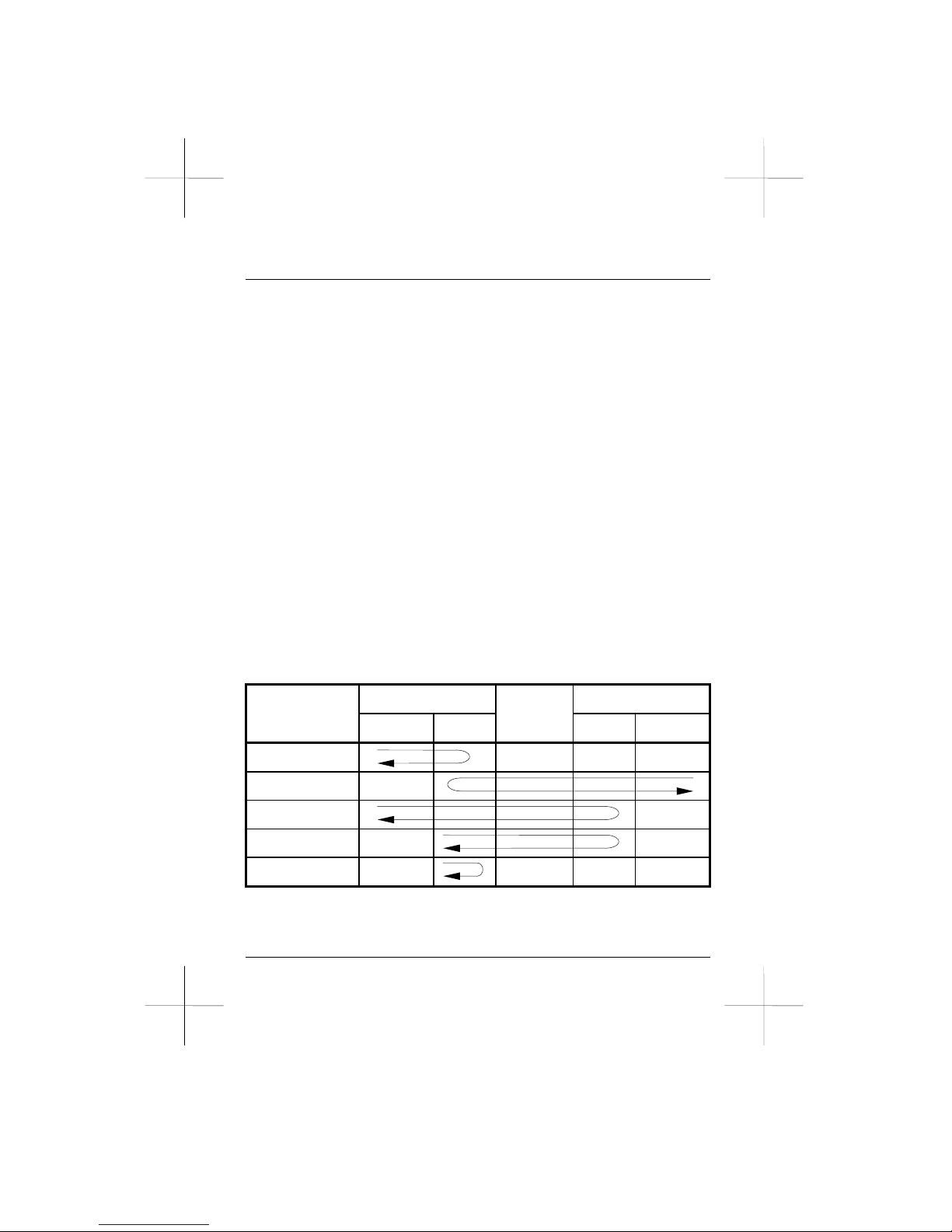
6.2 Preliminary Diagnostic Guide
A communications problem can stem from the telephone company
circuit, local computer, remote computer, modem, or the remote
modem. Even if the communications path is in order, communications
software parameters may be set incorrectly.
The following are suggestions regarding diagnostic tests. Note that all
tests should be initiated when the modem is in asynchronous command
state with both the computer and modem set to full duplex operation.
1. To determine a failure due to the modem, perform an LALST test.
This test verifies the modem itself.
2. To determine a failure due to the computer, perform LAL and
LALST tests. If an LAL test fails but an LALST passes, the
computer (or path) is probably at fault.
3. To determine a failure due to a faulty telephone circuit, perform
LAL and RDLST tests to both the local modem and the remote
modem. If both modems pass an LAL test but fail an RDLST test,
the telephone circuit is probably at fault.
Modem problems most often arise from poor quality telephone lines. It
is advisable that your modem is on a good direct line (without PBX).
Local Side Remote Side
Computer Modem Modem Computer
&T1(LAL)
&T3(LDL)
&T6(RDL)
&T7(RDLST)
&T8(LALST)
Telephone
Page: 72
Page 73
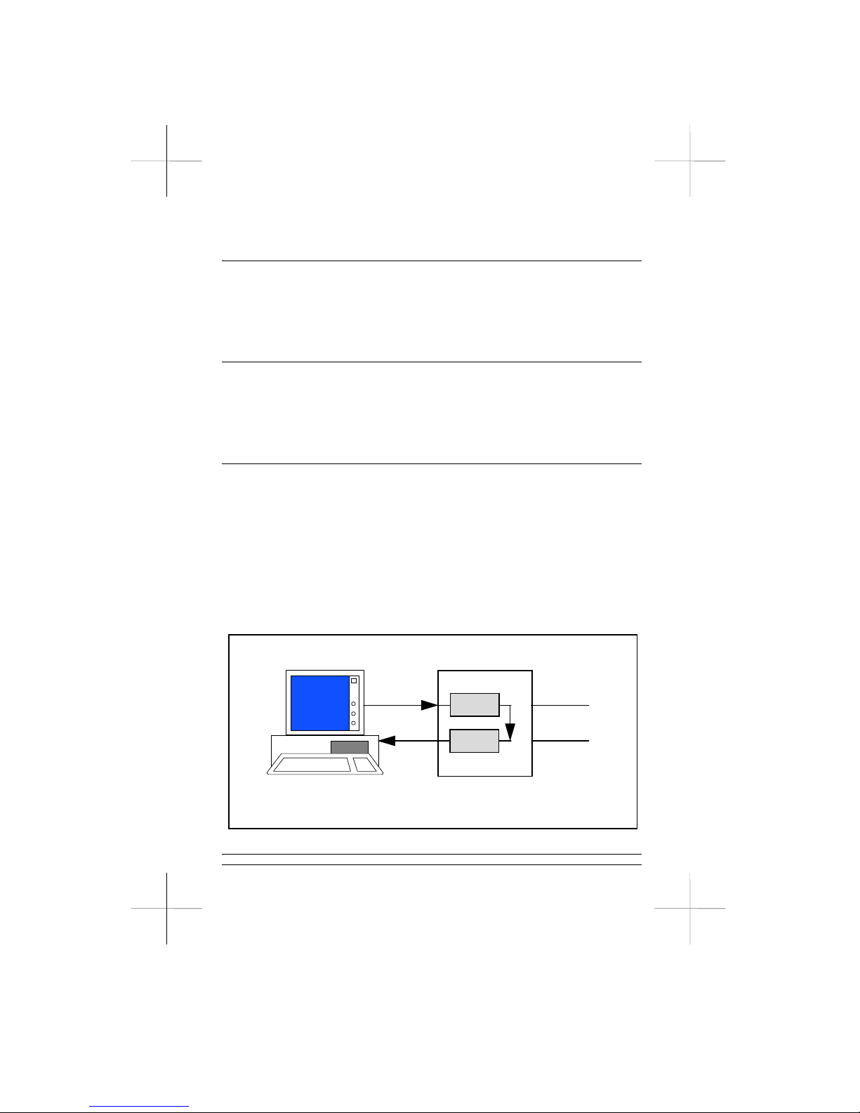
6.3 Using the Test Timer S18
Register S18 determines all selftest duration’s, and the modem
automatically ends tests and returns to command state when the S18
time expires. The S18 default is zero, to disable the test timer.
6.4 Ending a Test &T0
A test can be terminated at any time by issuing the escape sequence,
causing the modem to enter command state and then issue AT&T0.
Any command following &T0 in a command line is ignored.
6.5 Local Analog Loopback Test &T1
The local loopback test (LAL) verifies the path between the computer
and the modem. Everything you type on the keyboard during the test
will be echoed by the modem back to the computer.
To initialize an LAL test, issue AT&T1. The test begins after the
modem responds with a carriage return and a line feed. Type any
character string on the keyboard, and the string should appear correctly
on the screen. If errors are found, the modem, computer or path might
be at fault.
Telephone Line
Receiver
Transmitter
Analog Loop
Local Computer
Figure 6-1 Local Digital Loopback Test
6.6 Local Digital Loopback Test &T3
Page: 73
Page 74
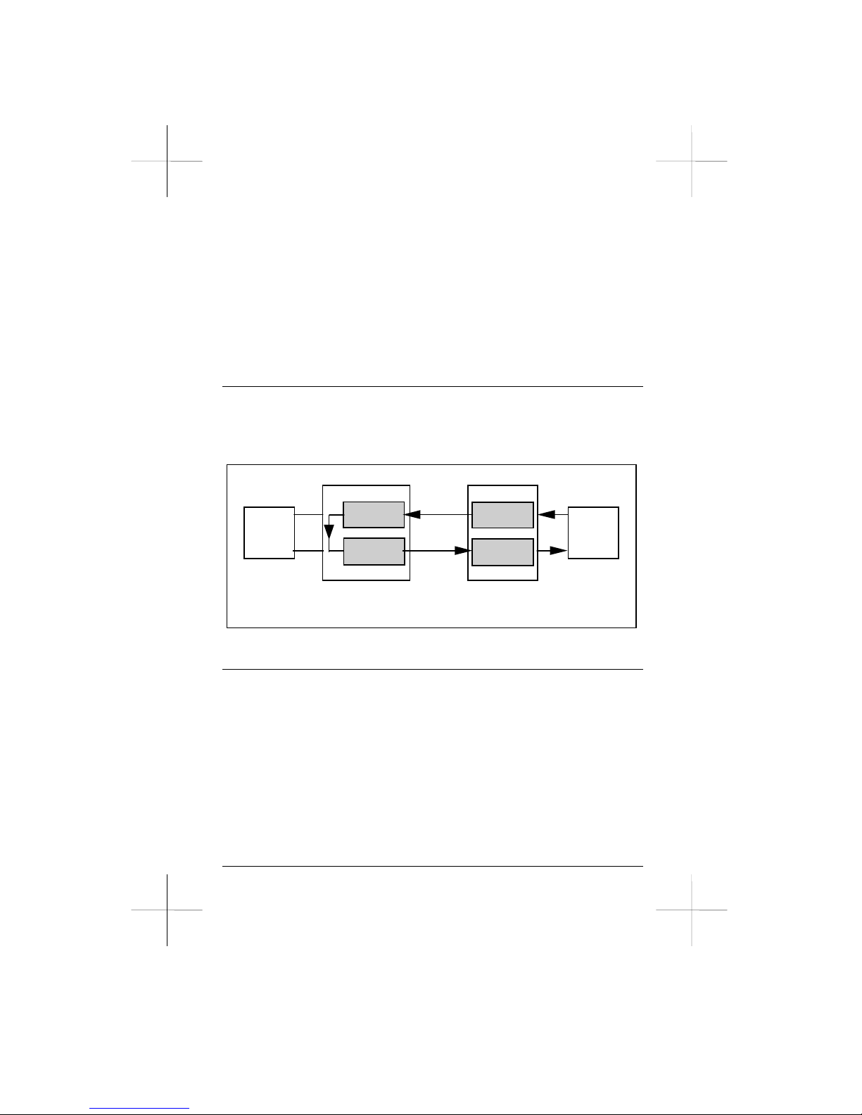
The local digital loopback test (LDL) verifies both the modem and the
telephone circuit. This is primarily used to permit a modem that is not
ITU-T V.54 compatible to engage in an RDL test with your modem.
To initialize the test, issue command AT&T3 with your modem on-line
and in command state. Your modem will loop the data it receives back
to the remote station so the remote modem can perform an RDL test
with your modem.
6.7 Grant or Deny RDL Request &T4/&T5
Issue AT&T4 as the default if you want the modem to accept an RDL
test request from a remote modem. Issue AT&T5 to prohibit the
modem from accepting an RDL test request.
Local
computer
Digital Loop
Transmitter
Receiver
Local Modem
Telephone
Line
Remote Modem
Transmitter
Receiver
Remote
computer
TD
RD
Figure 6-2 Local Digital Loopback Test (&T3)
6.8 Remote Digital Loopback Test &T6
The remote digital loopback test (RDL) verifies the local computer and
modem, the telephone circuit and the remote modem. Issue AT&T6 to
initiate the test. Note that the remote modem should issue AT&T4 to
accept the digital loopback request.
The test begins after the modem has sent a carriage return and line feed.
Type any character string on the keyboard and the string should appear
correctly on the screen. If errors are found, either your computer, your
modem, the remote modem or the telephone circuit is at fault. You can
initiate LAL tests on both local and remote sides to further isolate the
Page: 74
Page 75
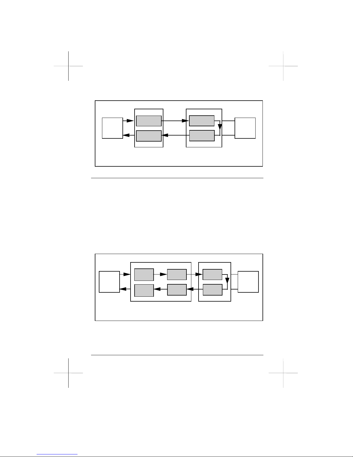
problem.
Local
computer
Digital Loop
Transmitter
Receiver
Local Modem
Telephone
Line
Remote Modem
Transmitter
Receiver
Remote
computer
TD
RD
Figure 6-3 Remote Digital Loopback Test (&T6)
6.9 Remote Digital Loopback with Selftest &T7
The remote digital loopback selftest RDLST) verifies the local modem,
telephone circuit and remote modem. In this test, your modem sends a
self-generated test message to the remote modem. The remote modem
then loops the test message back to your modem and your modem
compares the received string with the original message to verify the
path. To initiate the test, issue either of the following command lines
when on-line in asynchronous command state.
AT S18=0 &T7 Test timer is disabled.
AT S18=30 &T7 Test timer is set for 30 seconds.
Local
computer
Local Modem
Digital Loop
Remote Modem
Transmitter
Receiver
Remote
computer
TD
RD
Transmitter
Receiver
Test
Pattern
Generator
Error
Counter
Figure 6-4 Remote Digital Loopback with Selftest (&T7)
The test begins after the modem sends a carriage return and line feed.
To terminate the test when S18 is set to zero, use the escape sequence
to bring the modem to command state and issue command AT&T0.
Page: 75
Page 76
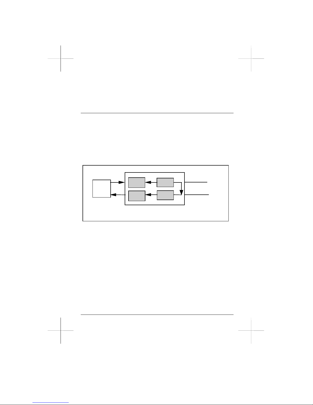
The modem then lists the number of errors detected within the time
interval. A value of 000 means no errors and 255 means 255 or more
errors.
6.10 Local Analog Loopback with Selftest &T8
In the local analog loopback selftest (LALST), the modem generates a
test pattern to verify itself. Issue either of the following command lines
to initiate the test.
AT S18=0 &T8 Test timer is disabled.
AT S18=30 &T8 Test timer is set for 30 seconds.
The test begins after the modem sends a carriage return and line feed.
Local
computer
TD
RD
Analog Loop
Transmitter
Receiver
Test
Patte rn
Generator
Error
Counter
Telephone Line
Figure 6-5 Local Analog Loopback with Selftest (&T8)
When the test is terminated, the modem responds with the number of
errors detected during the test. A value of 000 means no errors and 255
means 255 or more errors.
Page: 76
Page 77

Appendix A
MODEM REGISTERS
Modem registers determine operation characteristics. Appendix A
describes each register individually, except for registers which cannot
be modified. Registers in bold represent default settings.
Reading or Changing a Register
To read the current content of a register, issue command Sr?. To
change the register, use command Sr=.
For example:
AT S7? Reads register S7.
AT S7=150 Sets register S7 to 150.
AT S0?S16? Reads registers S0 and S16.
Auto Answer Ring Number S0
Range: 0-255 Unit: Ring Default: 0
Register S0 determines the number of rings before the modem answers
a call.
For example:
S0=0 Will not auto answer calls.
S0=3 Answers incoming calls after the third ring.
Ring Count S1
Register S1 counts the number of rings on the telephone line when the
modem is set to auto answer. Register S1 is cleared eight seconds after
the last ring. The default is 0.
Page: 77
Page 78

Escape Character S2
Range: 0-127 Unit: ASCII Default: 43
Register S2 stores the escape character ASCII decimal value. Default
value 43 is an ASCII "+."
Carriage Return Character S3
Range: 0-127 Unit: ASCII Default: 13
Register S3 stores the carriage return character ASCII decimal value,
which terminates the command line and the response code.
Line Feed Character S4
Range: 0-127 Unit: ASCII Default: 10
Register S4 stores the line feed character ASCII decimal value, which
follows a carriage return after a response code is sent. You might need
to set this register to a different value if a non-standard DTE is used.
Backspace Character S5
Range: 0-32,127 Unit: ASCII Default: 8
Register S5 stores the backspace character ASCII decimal value, which
is used as the backspace key for editing and as the echoed character to
move the cursor backwards on the screen.
Wait Time Before Dialing S6
Range: 2-255 Unit: sec Default: 2
Register S6 determines how long the modem waits (after off hook)
before proceeding to dial. This delay allows the central office to detect
the off hook line status and apply a dial tone. If the delay time is too
short, the modem will start dialing too early and the call will not go
through because the central office did not receive the first few dialing
Page: 78
Page 79

digits.
Register S6 is valid only when X0, X1, or X3 is in effect. If X2 or X4
are in effect, dial tone detection is enabled and the modem will not
blind dial.
Wait for Carrier After Dialing S7
Range: 2-255 Unit: sec Default: 45
Register S7 determines how long the modem waits for a remote carrier
signal after dialing or answering. If a carrier is detected, the modem
goes on-line. Otherwise, the modem disconnects and responds with
NO CARRIER.
Pause Time for a Comma (,) Dial Modifier S8
Range: 0-255 Unit: sec Default: 2
Register S8 determines how long the modem pauses when a comma
command is given.
For example:
ATDP9,782-2456 Instructs the modem to dial the PBX access
number 9 and then pause for 2 seconds
before dialing 782-2456.
More than one comma command can be combined for a longer delay.
Carrier Detect Response Time S9
Range: 1-255 Unit: 0.1sec Default: 6
Register S9 determines how long a carrier signal must continuously
exist before it is recognized as a valid signal by the modem. A longer
S9 time gives the modem more time to distinguish the carrier signal
from noise.
Loss of Carrier to Hang Up Delay S10
Page: 79
Page 80

Range: 1-255 Unit: 0.1sec Default: 14
Register S10 determines how long the modem waits before hanging up
after detecting a loss of carrier. This delay permits the carrier to
momentarily disappear without causing the modem to disconnect. If
this register is set to 255, the modem will ignore carrier status as
though a carrier were always present.
Always set S10 to a value larger than S9. The acceptable length of time
for momentary carrier loss is the difference between S10 and S9.
Touch Tone Dialing Speed S11
Range: 50-255 Unit: ms Default: 95
Register S11 determines the touch tone dialing speed. This register sets
tone duration and spacing during touch tone dialing. The default is
approximately 5.26 digits per second.
Escape Code Guard Time S12
Range: 0-255 Unit: 20ms Default: 50
Register S12 determines the required guard time before the first escape
characters and after the last escape characters are entered. This allows
the modem to distinguish the escape command from transmission data.
Leased Line Dialup Backup Times S13
Range: 0-255 Default: 5
Bits Mapped S14
Bit 0: Reserved.
Bit 1: 0 Disable command echo. (E0)
1 Enable command echo. (E1)
Bit 2: 0 Enable result code. (Q0)
1 Disable result code. (Q1)
Page: 80
Page 81

Bit 3: 0 Short form result code. (V0)
1 Long form result code. (V1)
Bit 4: 0 Smart mode state.
1 Dumb mode state.
Bit 5: 0 Tone dial calls. (T)
1 Pulse dial calls. (P)
Bit 6: 0 Smart modem. (@I0)
1 Dumb modem. (@I1)
Bit 7: 0 Answer state. (A, S0=1)
1 Originate state. (D)
Leased Line Dialup Backup Timer S15
Range 0-255 Unit: min Default: 5
Bits Mapped S16
Bit 0 0 Disable Local Analog Loopback Test.
1 Enable Local Analog Loopback Test. (&T1)
Bit 1 0 Disable Local Digital Loopback Test.
1 Enable Local Digital Loopback Test. (141)
Bit 2 0 Disable Local Digital Loopback Test.
1 Enable Local Digital Loopback Test. (&T3)
Bit 3 0 Loopback state OFF.
1 Loopback state in progress.
Bit 4 0 Disable Remote Digital Loopback Test.
1 Enable Remote Digital Loopback test. (&T6)
Bit 5 0 Disable Remote Digital Loopback Selftest.
1 Enable Remote Digital Loopback Selftest. (&T7)
Bit 6 0 Enable Local Analog Loopback Test.
1 Disable Local Analog Loopback Test. (&T8)
Bit 7 0 Enable Remote Digital Loopback Test.
Page: 81
Page 82

1 Disable Remote Digital Loopback Test. (140)
Carrier Detect (CD) Timer S17
Range: 0-255 Unit: 0.1sec Default: 10
Register S17 determines how long after CD off the auto retrain begin.
Test Timer S18
Range: 0-255 Unit: Second Default: 0
Register S18 determines the length of a diagnostic test before
termination. The default 0 means the test timer is disabled.
Auto Redial Interval Time S19
Range: 0-255 Unit: sec Default: 2
Bits Mapped S20
Bit 0-3 0 Try dialup redial times. (N)
Bit 4-7 2 Try leased line rehandshake times. (-B)
Bits Mapped S21
Bit 0 0 RJ-11/41S/45S modular jack.
1 RJ12-12/13 modular jack.
Bit 1: 0 DSR always ON. (&S0)
1 DSR reflects real. (&S1)
Bit 2: 0 CTS tracks RTS. (&R0)
1 CTS always ON. (&R1)
Bit 3,4 0 Ignore DTR. (&D0)
1 DTR ON to OFF causes command state. (&D1)
2 DTR ON to OFF causes hang up. (&D2)
3 DTR ON to OFF causes initialization. (&D3)
Page: 82
Page 83

Bit 5 0 DCD always ON. (&C0)
1 DCD reflects real. (&C1)
Bit 6,7 0 Disable special disconnect. (Y0)
1 Enable long space disconnect. (Y1)
2 Enable clear down disconnect. (Y2)
Bits Mapped S22
Bit 0,1 0 Speaker volume off.
1 Speaker volume low.
2 Speaker volume medium.
3 Speaker volume high.
Bit 2,3 0 Disable speaker. (M0)
1 Speaker on until carrier detected. (M1)
2 Speaker always on. (M2)
3 M1, but speaker off during dialing. (M3)
Bit 4-6 0 Short connect result code. (X0)
1 Full connect result code. (X1)
2 Wait for dial and check answer. (X2)
3 Check busy and answer. (X3)
4 Wait for dial, check busy and answer. (X4)
5-7 Reserved.
Bit 7 0 Make/break ratio 39/61. (&P0)
1 Make/break ratio 33/67. (&P1)
Bits Mapped S23
Bit 0 0 Disable request from RDL. (&T5)
1 Enable request from RDL. (&T4)
Bit 2 0 Disable 140 active RDL.
1 Enable 140 active RDL.
Bit 3 0 Disable 142 active.
1 Enable 142 active.
Bit 4,5 0 Reserved.
Page: 83
Page 84

Bit 6,7 0 Guard tone disable. (&G0)
1 Guard tone 550 Hz. (&G1)
2 Guard tone 1800 Hz. (&G2)
3 Reserved.
Bits Mapped S24
Bit 0 0 Disable V25bis mode. (*C0)
Bit 1 0 Enable V25bis asyncronous mode. (*C1)
1 Enable V25bis synchronous mode.
Bit 2 0 Enable V25bis HDLC mode. (*C3)
1 Enable V25bis Bisynchronous mode. (*C2)
Bit 3-7 0 Reserved.
Delay to DTR S25
Range: 0-255 Unit: sec or 10 ms Default: 5
Register S25 determines how long the modem waits in sync/async
mode from connection sequence completion to DTR status
examination. This delay allows the modem to be switched from an
asynchronous data terminal to a synchronous data terminal without
breaking the connection. In this mode the unit register is in seconds
and the default is 5 seconds.
In asynchronous and other synchronous modes, a DTR change (ON or
OFF) which lasts for less than the time defined by register S25 is
ignored by the modem. In these modes the unit register is 10
milliseconds and the default is 0.05 seconds.
Page: 84
Page 85

RTS to CTS Delay Interval S26
Range: 0-255 Unit: 10 ms Default: 0
Register S26 determines how long the modem waits from an RTS
OFF-to-ON transition detection to the time CTS is turned on. This
register is valid only in synchronous mode with &R0 in effect.
Bits Mapped S27
Bit 0-2 0 Asynchronous mode. (&M0)
1 Synchronous mode 1. (&M1)
2 Synchronous mode 2. (&M2)
3 Synchronous mode 3. (&M3)
Bit 3 0 Normal speed pulse dialing.
1 Fast speed pulse dialing.
Bit 4,5 0 Local modem synchronous transmit clock
source. (&X0)
1 Local DTE synchronous transmit clock source.
(&X1)
2 Remote modem synchronous transmit clock
source. (&X2)
3 Reserved.
Bit 6,7 0 ITU-T/Bell auto mode. (B0)
1 Bell 103, 212A mode. (B1)
2 ITU-T V.23 back channel. (B2)
3 ITU-T V.23 main channel. (B3)
Bits Mapped S28
Bit 0-4
0 75bps serial port speed.
1 110bps serial port speed.
2 300bps serial port speed.
3 600bps serial port speed.
4 1200bps serial port speed.
Page: 85
Page 86

5 2400bps serial port speed.
6 4800bps serial port speed.
7 7200bps serial port speed.
8 9600bps serial port speed.
9 12000bps serial port speed.
10 14400bps serial port speed.
11 16800bps serial port speed.
12 19200bps serial port speed.
13 21600bps serial port speed.
14 24000bps serial port speed.
15 26400bps serial port speed.
16 28800bps serial port speed.
17 38400bps serial port speed.
18 57600bps serial port speed.
19 115200bps serial port speed.
Bit 5,6 0 Serial port even parity.
1 Serial port space.
2 Serial port odd parity.
3 Serial port none/mark.
Bit 7 0 Serial port, 8 data bits.
1 Serial port, 7 data bits.
Bits Mapped S29
Bit 0,1 0 DCE, 5 data bits.
1 DCE, 6 data bits.
2 DCE, 7 data bits.
3 DCE, 8 data bits.
Bit 2,3 0 DCE, none parity.
1 DCE, space parity.
2 DCE, even parity.
3 DCE, odd parity
Bit 4 0 DCE, 1 stop bit.
1 DCE, 2 stop bits.
Page: 86
Page 87

Bit 5-7 0 Reserved.
Set Major SCP as Default S30
Default: 1 1<=n<=4 (&Yn)
Set Call Back Delay Timer S31
Default: 10 Unit: sec 0<=n<=255 (@Dn)
Bit 1 0 Disable 141 active RDL.
1 Enable 141 active RDL.
Bits Mapped S32
Bit 0 0 Disable ring sound. (@B0)
1 Enable ring sound. (@B1)
Bit 1 0 Disable call back security. (@A0)
1 Enable call back security. (@A1)
Bit 2 0 Disable hardware data security. (@E0)
1 Enable hardware data security. (@E1)
Bit 3 0 Open message working bit.
1 Close message working bit.
Bit 4 0 Disable V.32 forward/backward link.
1 Enable V.32 forward/backward link.
Bit 5 0 Command AT&Z working bit.
1 Command AT@Z working bit.
Bit 6,7 0 Dialup line. (&L0)
1 2 wire leased line. (&L1)
2 4 wire leased line. (&L2)
Page: 87
Page 88

Service Class S33
Bit 0-5 0 Reserved.
Bit 6 0 MNP synchronous link. (@L0)
1 MNP asynchronous link. (@L1)
Bit 7 0 Disable second channel.
1 Enable second channel.
Bits Mapped S34
Bit 0 0 V.32 TCM.
1 V.32 QAM.
Bit 1 0 Disable ignore DTR dump in handshaking.
1 Enable ignore DTR dump in handshaking.
Bit 2,3 0 RLSD on -43dBm, off -48dBm.
1 RLSD on -33dBm, off -38dBm.
2 RLSD on -26dBm, off -31dBm.
3 RLSD on -16dBm, off -21dBm.
Bit 4,5 0 Normal AT&F ATZ.
1 Quick ATZ.
2 Quick AT&F.
3 Quick AT&F ATZ.
Bit 6,7 0 Reserved.
Bits Mapped S35
Bit 0-3 0-9 STN for power on auto dial. (&A0~9)
15 Disable power on auto dial. (&A99)
Bit 4,5 0 Disable all. (@Y0)
1 Dialup line simulate leased line. (@Y1)
2 Leased line backup dialup line. (@Y2)
Bit 6 0 Single phone system. (-M0)
Page: 88
Page 89

1 Multi-phone system. (-M1)
Bit 7 0 Disable disconnect reset.
1 Enable disconnect reset.
Set Auto Reliable Fallback Character S36
Default: 0 0<=n<=127 Unit: ASCII (%An)
Modem Port Link Speed S37
Default: Range: 0-17
0 Auto (follow AT speed)
1 Attempt connection at 1200/75 bps
2 Attempt connection at 300 bps
3 Attempt connection at 600 bps
4 Attempt connection at 1200 bps
5 Attempt connection at 2400 bps
6 Attempt connection at 4800 bps
7 Attempt connection at 7200 bps
8 Attempt connection at 9600 bps
9 Attempt connection at 12000 bps
10 Attempt connection at 14400 bps
11 Attempt connection at 16800 bps
12 Attempt connection at 19200 bps
13 Attempt connection at 21600 bps
14 Attempt connection at 24000 bps
15 Attempt connection at 28800 bps
16 Attempt connection at 31200 bps
17 Attempt connection at 33600 bps
Bits Mapped S39
Bit 0 0 Disable data compresssion. (%C0)
1 Enable data compression. (%C1)
Bit 1,2 0 Disable auto retrain. (%E0)
1 Auto retrain on same speed. (%E1)
Page: 89
Page 90

2 Auto retrain with speed change.(%E2)
3 Reserved.
Bit 3,4 0 Neither direction.
1 TX direction only.
2 RX direction only.
3 Both directions.
Bit 5 0 Enable answer tone check.
1 Disable answer tone check.
Bit 6 0 Enable compromise equalizer.
1 Disable compromise equalizer.
Bit 7 0 Disable detect phase.
1 Enable detect phase.
Bits Mapped S40
Bit 0 0 Disable remote access. (*E0)
1 Enable remote access. (*E1)
Bit 1-4 0 Reserved.
Bit 5 0 Disable remote access security.
1 Enable remote access security.
Bit 6,7 0 Reserved.
Remote Access Attention Character S41
Default: 42 0<=n<=255 Unit: ASCII
V.42bis Compression Dictionary Max. String Length S4
Default: 16 0<=n<=255 Unit: Byte
Page: 90
Page 91

Bits Mapped S43
Bit 0,1 0 Set maximun MNP block to 64 characters. (\A0)
1 Set maximum MNP block to 128 characters.
(\A1)
2 Set maximum MNP block to 192 characters.
(\A2)
3 Set maximum MNP block to 256
characters.(\A3)
Bit 2 0 Reserved.
Bit 3,4 0 Set maximum dictionary size to 512 entries.
1 Set maximum dictionary size to 1024 entries.
2 Set maximum dictionary size to 2048 entries.
3 Set maximum dictionary size to 4048 entries.
Bit 5 0 Reserved.
Bit 6,7 0 Does not buffer data. (\C0)
1 Buffers data for 4 seconds until 200 characters
or when a SYN character is detected, then
switches to normal. (\C1)
2 Does not buffer data, switches to normal. (\C2)
3 Reserved.
Bits Mapped S44
Bit 0 0 Reserved.
Bit 1 0 Reserved.
Bit 2 0 Disable on-line data echo. (\E0)
1 Enable on-line data echo. (\E1)
Bit 3 0 Disable modem port flow. (\G0)
1 Enable modem port flow. (\G1)
Bit 4-6 0 Reserved.
Bit 7 0 Independent serial port speed connection. (\J0)
1 Dependent serial port speed connection. (\J1)
Page: 91
Page 92

Bits Mapped S45
Bit 0-2 0 Break control type. (default: 5)
0<=n<=5 (\Kn)
Bit 3 0 Stream link (interactive).
1 Block link (file transfer).
Bit 4 0 Disable fixed DCE speed. (%H0)
1 Enable fixed DCE speed. (%H1)
Bit 5-7 0 Normal Mode. (\N0)
1 Direct mode. (\N1)
2 MNP mode. (\N2)
3 Auto reliable mode. (\N3)
4 LAPM mode. (\N4)
5 LAPM ® normal mode.
6 LAPM ® MNP mode.
7 MNP ® normal mode.
Bits Mapped S46
Bit 0-2 0 Disable flow control. (\Q0)
1 Enable bi-directional XON/XOFF flow
control.(\Q1)
2 Enable uni-directional hardware flow
control.(\Q2)
3 Enable bi-directional hardware flow
control.(\Q3)
4 Enable uni-directional XON/XOFF flow control.
(\Q4)
5 CTS off until connection and \Q2. (\Q5)
6 CTS off until connection and \Q3. (\Q6)
Bit 3 0 RI on after handshake.
1 RI off after handshake.
Bit 4-6 0 Disable V42/MNP result code. (\V0)
1 Enable V42/MNP4 result code in DTE speed.
(\V1)
Page: 92
Page 93

2 Enable V42/MNP4 result code in DCE speed.
(\V2)
3 Enable V42bis/MNP5 result code in DTE speed.
(\V3)
4 Enable V42bis/MNP5 result code in
DCEspeed. (\V4)
5 Enable V42bis/MNP5 debug code in DTE
speed.
6 Enable V42bis/MNP5 debug code in DCE
speed.
Bit 7 0 Process flow control character. (\X0)
1 Process flow control character and pass through
to local or remote system. (\X1)
Inactivity Timer S47
Default: 0 0<=n<=255 Unit: min (\Tn)
Wait for Connection Password S48
Range: 0-255 Unit: Second Default: 15
Register S48 determines how many seconds the modem waits for a
connection password after it answers an incoming call. If the password
is not received during this period, the modem will hang up.
Redial Limit S49
Range: 0-15 Default: 10 Unit: Times
Dialup Line TX Level S50
Range: 0-15 Default: 1 Unit:-dBm
Page: 93
Page 94

Leased-Line TX Level S51
Range: 0-31 Default: 1 Unit: -dBm
Bits Mapped S52
Default: 0
Bit 0-7 0 Auto speed.
1 Others the same as register S28.
Bits Mapped S53
Bits 0-3 8 RI reset timer.
Bit 4 0 Disable V25 calling tone.
1 Enable V25 calling tone.
Bit 5 0 Disable T30 calling tone.
1 Enable T30 calling tone.
Bit 6,7 0 Reserved.
Bits Mapped S54
Default: 0
Bit 0-2 0 V.34 auto mode. (-V0)
1 V.FC auto mode. (-V1)
3 V.32bis auto mode. (-V2)
4 V.34, V.FC, V.32bis.(-V3)
5 V.FC, V.32bis. (-V4)
6 V.34 only. (-V5)
7 V.FC only. (-V6)
8 V.32bis only. (-V7)
Bit 3-7 0 Reserved.
Page: 94
Page 95
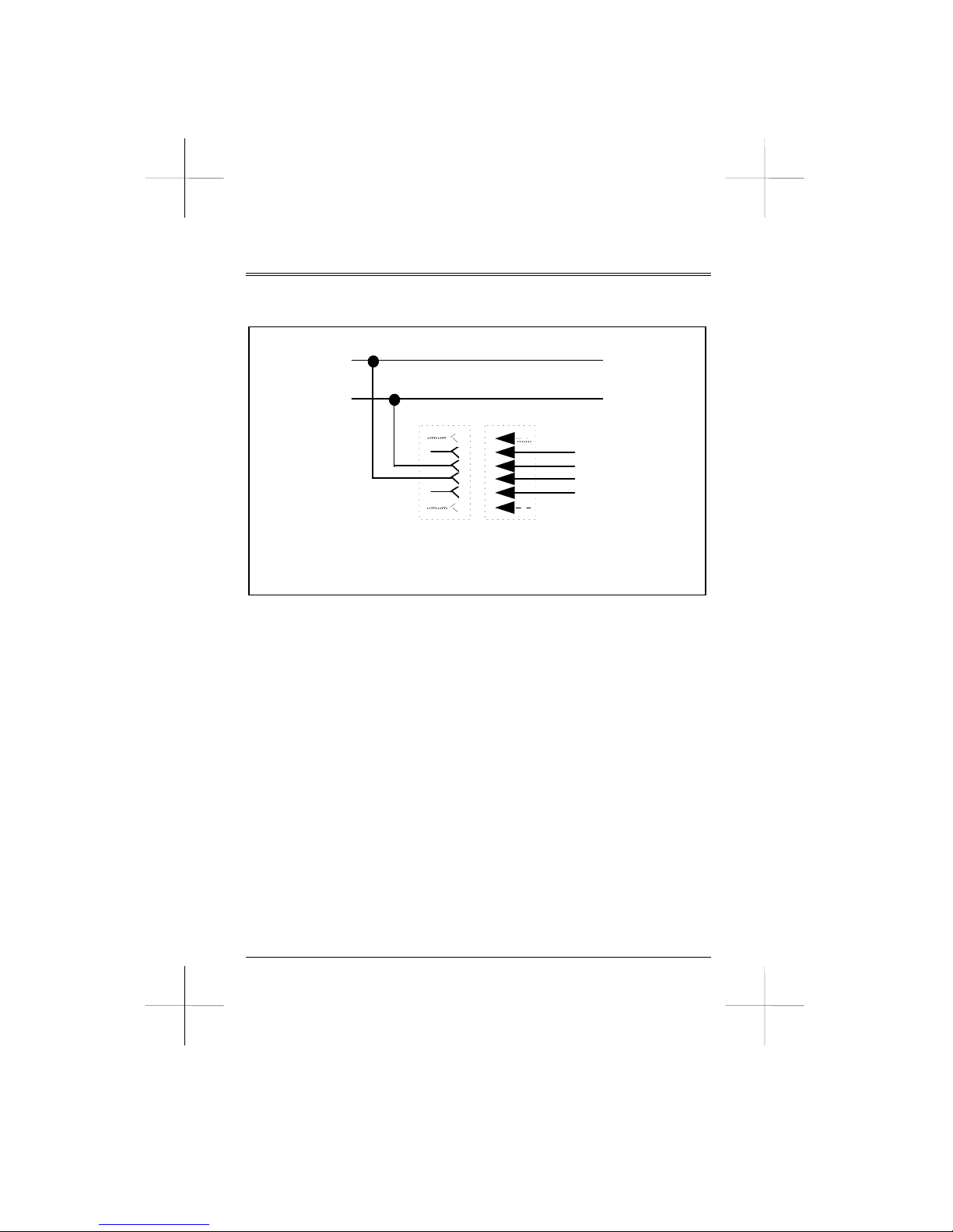
Appendix B
MODULAR JACK WIRING DIAGRAM
R
To Other
Equipment
Telephone
Line
T
2
3
5
To
M
ode
m
2
3
5
R
T
JACK
PLUG
Fig B-1 RJ-11/JM8 Modular Jack Wiring Diagram
Page: 95
Page 96
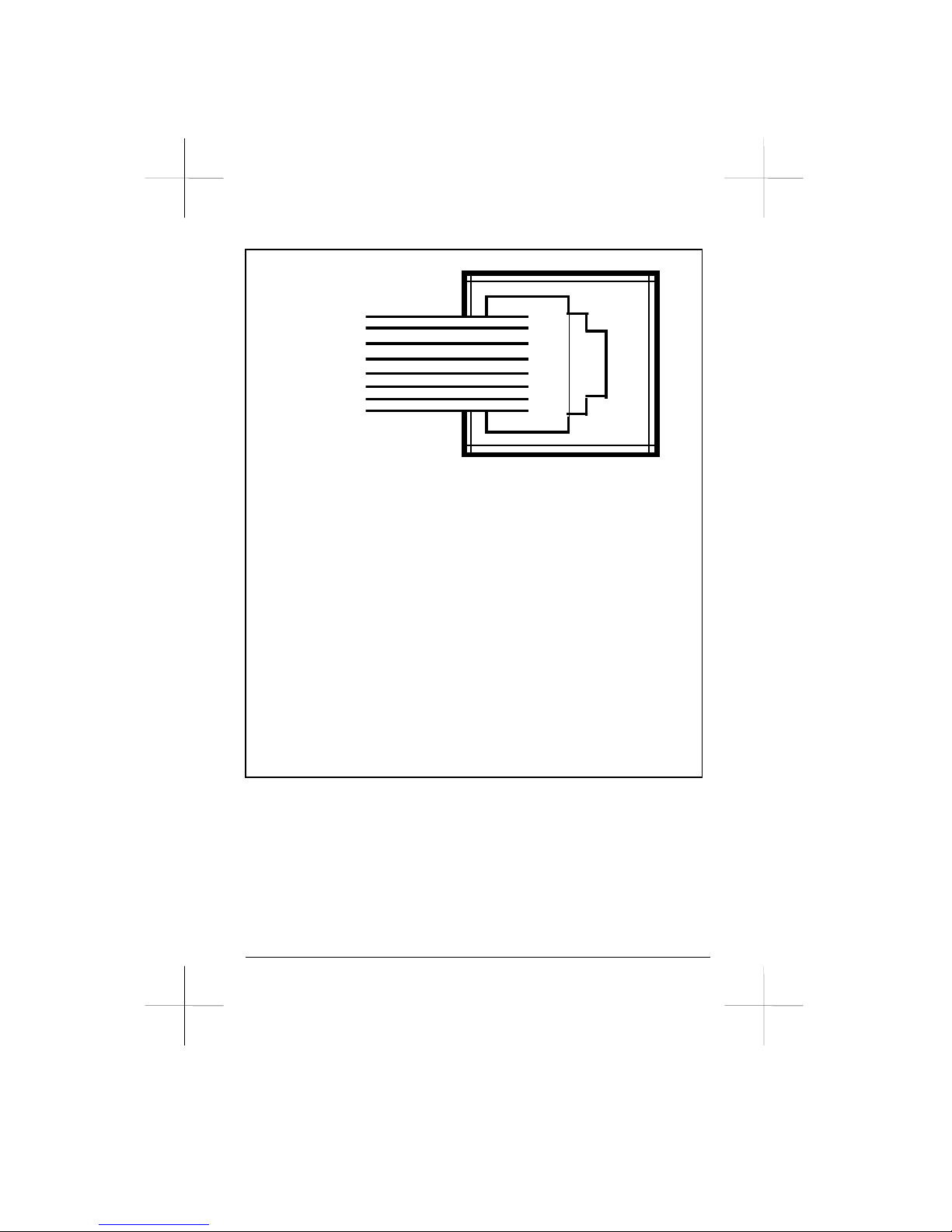
Page: 96
Pin 8
7
6
5
4
3
2
1
CONNECTIONS
Phone Line: Connect Pin 4 & Pin 5
2-Wire Leased-Line: Connect Pin 1 & Pin 2
4-Wire Leased-Line:
Local Remote
Pin 1 (TX) ----------------- Pin 7 (RX)
Pin 2 (TX) ----------------- Pin 8 (RX)
Pin 7 (RX) ----------------- Pin 1 (TX)
Pin 8 (RX) ----------------- Pin 2 (TX)
Fig B-2 RJ-45 Modular Jack Wiring Diagram
Page 97
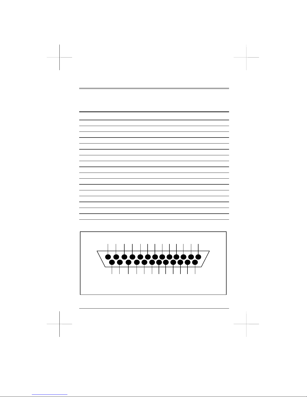
Appendix C
RS-232 PIN ASSIGNMENT
RS-232 V.24 Description Signal Direction
1 AA 101 Protective Ground computer Ù modem
2 BA 103 Transmit Data computer Ö modem
3 BB 104 Receive Data computer Õ modem
4 CA 105 Request to Send computer Ö modem
5 CB 106 Clear to Send computer Õ modem
6 CC 107 Data Set Ready computer Õ modem
7 AB 102 Signal Ground computer Ù modem
8 CF 109 Carrier Detected computer Õ modem
12 CI 112 Select Alternate Rate computer Õ modem
15 DB 114 Transmit Clock computer Õ modem
17 DD 115 Receive Clock computer Õ modem
18 141 Loopback/Maintenance computer Ö modem
20 CD 108 Data Terminal Ready computer Ö modem
21 CG 140 Local Loopback computer Ö modem
22 CE 125 Ring Indicator computer Õ modem
23 CI Select Alternate Rate computer Õ modem
24 DA 113 Transmit Clock computer Ö modem
25 142 Test Indicator computer Õ modem
* Pin CI outputs on both pin 12 (Bell 103) and pin 23 (EIA RS-232)
13 12 11 10 9 8 7 6 5 4 3 2 1
25 24 23 22 21 20 19 18 17 16 15 14
Fig C-1 RS-232 Connector (DB-25) Pin Assignment
Page: 97
Page 98

Appendix D
FAX COMMAND REFERENCE
Appendix D explains individual fax commands and is designed for
value added users who want to write fax communication software.
General users may skip this section.
Fax Auto Answer +FAA=
This command instructs the faxmodem to auto answer in data mode or
in fax mode.
+FAA=0 Auto answers as a +FCLASS type faxmodem.
+FAA=1 Automatically determines whether to answer as a fax
or data modem.
Service Class Indication +FCLASS=
This command determines whether the faxmodem is in fax or data
mode. It also indicates the fax command set service class.
+FCLASS=0 Data mode.
+FCLASS=2 Class 2 mode.
+FCLASS=? Inquires service class capability.
+FCLASS? Inquire service class identification.
Capability to Receive +FCR=
This command inquires about receive function capability.
+FCR=0 Indicates the faxmodem will not receive message data
and is not able to poll a remote device.
+FCR=1 Indicates the faxmodem can receive message data.
Page: 98
Page 99

Fax Capability Parameter +FDCC=
Syntax:+FDCC=VR,RB,WD,LN,DF,EC,BF,ST
This command determines the parameters required for fax communication operation. The following is a list of definitions and values for
each parameter.
VR Vertical Resolution
0 Normal mode, 98 lines per inch
1 Fine mode, 196 lines per inch
BR Bit Rate
0 2,400 bps, ITU-T V.27ter
1 4,800 bps, ITU-T V.27ter
2 7,200 bps, ITU-T V.29 or V.17
3 9,600 bps, ITU-T V.29 or V.17
4 12,000 bps ITU-T V.17
5 14,400 bps ITU-T V.17
WD Page Width
0 1,728 pixels in 215 mm
LN Page Length
0 A4 size, 297 mm
2 Unlimited length
DF Data Compression Format
0 1-D modified Huffman
EC Error Correction
0 Disable error correction
BF Binary File Transfer
0 Disable binary file transfer
Page: 99
Page 100

ST Scan Time Per Line
0 0 ms, VR = normal 0 ms, VR = fine
1 5 ms, VR = normal 5 ms, VR = fine
2 10 ms, VR = normal 5 ms, VR = fine
3 10 ms, VR = normal 10 ms, VR = fine
4 20 ms, VR = normal 10 ms, VR = fine
5 20 ms, VR = normal 20 ms, VR = fine
6 40 ms, VR = normal 20 ms, VR = fine
7 40 ms, VR = normal 40 ms, VR = fine
To display the current +FDCC parameter settings, issue command
+FDCC?.
Current Session Results +FDIS=
Syntax:+FDIS=VR,RB,WD,LN,DF,EC,BF,ST
This command determines how the faxmodem returns the negotiated
T.30 parameters for the current session. See the +FDCC= section for
parameter definitions. Command +FDIS=? displays the help message
of this command.
Begin or Continue Phase C Data Reception +FDR
This command initiates a transition to Phase C data reception and
forces a transition in the control software from command parsing to
background processing.
Note that you can only issue this command at the moment when
negotiation is complete and upon entering Phase C. Issuing this
command at any other time results in an ERROR message.
Page: 100
 Loading...